DYT BZ 磁力耦合器安装维护手册(DYT-BZ75)
- 格式:pdf
- 大小:561.78 KB
- 文档页数:16
Installation, Operation a nd Maintenance InstructionsERIEZ MAGNETICSH EADQUARTERS: 2200 ASBURY ROAD, ERIE, PA 16506–1440 U.S.A.W ORLD AUTHORITY IN ADVANCED TECHNOLOGY FOR MAGNETIC, VIBRATORY and INSPECTION APPLICATIONSSM-321DIntroductionThis manual applies to the two basic types of Eriez Magnetics SE-2400 electromagnets: chute style and suspended type. The slight differences in installation and maintenance procedures for these magnets are detailedin the text.A careful reading of these Installation, Operation and Maintenance Instructions will assure your magnet’s most efficient and dependable performance.If there are any questions or comments about the manual, please call Eriez Manufacturing at 814/835-6000 for assistanceCAUTION ‑ STRONG MAGNETThis equipment includes one or more extremely powerful magnetic circuits. The magnetic field may be much stronger than the Earth’s background field at a distance several times the largest dimension of the equipment.• If you use a heart pacemaker of similar device you must neverapproach the equipment because your device may malfunction in the magnetic field, with consequences up to and including death.• To avoid serious pinch‑type injuries caused by objects attracted to the magnet, keep all steel and iron objects well away from the equipment. Do not allow hands, fingers, and other body parts to be caught between the equipment and “workpiece” being lifted.• Keep credit cards, computer disks, and other magnetic storage devices away from the equipment because magnetically stored information may be corrupted by the magnetic field.• Keep electronic devices, such as computers or monitors, away from the equipment because exposure to the magnetic field may result in malfunction or permanent damage to such devices. Contact Eriez if you have a question regarding these precautions.CAUTIONSafety labels must be affixed to this product. Should the safety label(s) be damaged, dislodged or removed, contact Eriez for replacement.Suspended Electromagnets3Table of ContentsSUSpENDED ElECTROMAGNETSDESCRIPTION ......................................................................................................4INSTALLATIONGeneral ............................................................................................................5 Magnet Positions .............................................................................................5 Suspension Height (6)Burden Depth (6)Wiring ..............................................................................................................6OPERATION ..........................................................................................................7MAINTENANCE For Chute Type & Manual Cleaning Models . (7)For Self-Cleaning Models (7)WARNING .............................................................................................................8TROuBLESHOOTINGRectifier Troubleshooting Data Sheet (9)General ..........................................................................................................10 Adjustment Guide for Chute Magnets ...........................................................10 Adjustment Guide for Manual Cleaning units (11)Adjustment Guide for Self-Cleaning units (11)4Suspended electromagnets are heavy duty DCpowered separators designed for removing iron from material that is being moved on wide, non-troughed belts or other wide flat conveyors. The speciallydesigned box-shaped structure houses oil-cooled coils that generate a powerful magnetic field.These units are furnished in two styles: chute style and suspended, with the later being available in either a manual cleaning type or self-cleaning type.Suspended units can be installed in either Position 1 (over the conveyor head pulley) or Position 2 (across the width of the conveyor). Sizes are readily available to accommodate most any conveyor width.DescriptionManual cleaning magnets are intended for use where the amount of iron to be retrieved is not abnormally high. An adjustable means of suspension is achieved through use of four turn-buckles supplied with the unit. T o clean accumulated tramp iron from the magnet it is necessary to shut off the power.Self-cleaning units are basically manual cleaning magnets with short belt conveyors built around them to provide automatic discharge of tramp iron. They are suspended in the same manner as manual cleaners.FIGURE 1Typical SE-2400 suspended electromagnetFIGURE 2Typical SE-2400 chute electromagnetSuspended Electromagnets5InstallationGENERAluse care in uncrating to avoid damage to the equipment.Check the area where the magnet is to be installed for magnetic material. All magnetic material within the field of the magnet (up to 4' (122 cm) may become induced and tend to attract iron. This can interfere with the magnet’s performance. Change to non-magnetic material.For Chute Style: These are shipped with mounting pads suitably positioned for installation at the angle specified on the order (usually 45-60°). When positioned at the specified angle, the integral oil expansion chamber will be properly oriented. For Suspended Models: Be sure the magnet is oriented properly. In all installations, the external oil expansion chamber must be at right angles to the direction of material flow and on the high side if installed at an angle.Check the pressure relief valve located on the high end of the oil expansion chamber to make sure it is free to operate. This is done by pulling the stem and releasing it. It is spring loaded and will re-seat itself when released.MAGNET POSITIONS Chute StylePlace the magnet on a foundation with the face on the same plane as the working face of the chute. Holes are provided for foundation bolts to secure the unit in place once it has been positioned. Joints between the magnet and chute work should be as smooth as possible to assure an uninterrupted material flow and provision should be made for gaining access to the magnet face for removing accumulated iron (See Figure 3).Suspended Style position 1 (in‑line)The installation of a suspended magnet over thetrajectory of material discharged from the belt conveyor is referred to as POSITION 1 (See Figure 4 & 5).For optimum separation in Position 1 installations, provisions must be made to adjust the location of the magnet to suit the trajectory of the material.For Position 1 installations with conveyor belt speeds of less than 350 fpm (107 m/min), greater separation will be achieved by using a non-magnetic head pulley.If a Self-Cleaning unit is being installed, examine the area to make sure that the self-cleaning belt around the separator has adequate room to run properly and that provisions have been made to collect thedischarged tramp iron. A hinged non-magnetic splitter, adjustable in length, will be required to preventextracted tramp iron from re-entering the product.FIGURE 4Manual cleaning position 1FIGURE 5Self-cleaning position 1FIGURE 36FIGURE 6Manual cleaning position 2FIGURE 7Self-cleaning position 2Position the magnet so that the face of the belt is approximately 2" (50 mm) from the trajectory of the material being discharged. The centerline of the magnet should be approximately perpendicular to the material at that point.position 2 (Cross‑belt)Installation of the separator over the moving bed of material at right angles to the conveyor is referred to as POSITION 2 (See Figures 6 and 7). This location sometimes presents a more difficult separation problem than Position 1 and may require a lower suspension. Position 2 mounting is generally not recommended where belt speed is in excess of 350 fpm (107 m/min.).For Position 2 installations, steel conveyor idlers cannot be used in the length of the conveyor beneath the separator. Any conveyor idlers beneath the separator must be made of rubber, wood, or some other non-magnetic material.Both the Manual Cleaning and the Self-Cleaning units should be installed on the centerline of the material conveyor.SUSpENSION HEIGHTThese magnets are designed for 20" (51 cm)suspension height. This height should be considered a maximum and the magnet should be lowered as close to the actual burden as possible. When lowering the magnet to the burden, be sure that plowing does not occur. If the unit is a self -cleaning magnet, make sure that the separator belt has room to operate and discharge tramp iron properly. A clearance of 3" (75 mm) between the magnet or belt and the top of the burden should be maintained for self-cleaning units. This clearance can be reduced to 2" (50 mm) for manual cleaning units.BURDEN DEpTHThe best separator performance is achieved by controlling the burden depth. A plow or levelerpositioned above the conveyor and before the magnet will help level high spots or surges in Position 2 installations. For Position 1 installations, therecommended installation location is calculated on expected tonnage. Any variation from this rate changes the trajectory of the burden with respect to the workingsurface of the magnet and may result in poor separation.WIrINGWiring for Eriez electromagnets is very simple (See Figure 8). Connect the two DC leads from the DC power source to the two terminal posts in the magnet outlet box and tighten the terminal nuts.CAUTIONAfter installation and prior to start‑up, check the oil level at the Oil level plug located on the side corner of the magnet near the expansion tank. If the level is low, add oil of the type specified on the plate attached to the top of the magnet beside the Oil Fill plug.Installation (cont.)Suspended Electromagnets7CAUTIONDo not attempt to turn the terminal poststhemselves. This may result in internal damage.FIGURE 8Power from existing DC sourceLeads from DC Power SourceDC Kick- Absorbing SwitchOperationSTArT -UP OF SELF-CLEANING UNITS1. Be sure the frame is visibly square and has notbeen damaged or twisted.2.After installation, momentarily close the AC switch to the belt drive to determine if the belt tends to wander and, if so, in which direction.3.Belt Adjustmenta. The SE-2400 magnets have a four-pulley design and two tracking adjustments. The bottom tail pulley is initially used to take up the slack and track the belt. If tracking cannot be achieved by this adjustment, the small pulley located on the same end has a horizontal adjustment available to aid in tracking the belt.b. To track the belt, the pulley should be moved in a direction to tighten the belt on the side to which the belt wanders.NOTE: Never start the belt drive and allow it to run continuously until the belt is properly tracked.MaintenanceFOr CHUTE TYPE &MANUAL CLEANING MODELS:1. The oil level should be checked periodically. Thelevel must be maintained. Replace the oil as required with the same brand and type as noted on the plate beside the Oil Fill Plug. Do not attempt to mix brands or types since many substitutes for the original are not compatible. Check the oil level only when the magnet is cold.2. Be sure the expansion tank pressure relief valve is free. This should be checked frequently.NOTE: Normal external operating temperature of Eriez oil-cooled electromagnets is approximately 160°F (70°C) for air-cooled magnets,approximately 150°F (65°C). These temperatures are extremely hot to the touch. Skin burns at 130°F .FOr SELF-CLEANING MODELS:1. Lubricate bearings on a schedule consistent withother equipment in use with your product and environment. An NGL1 No. 2 lithium-base grease is recommended.2.Check V-belt tension frequently. Adjust by tightening the reducer torque arm as required.3.For motor and reducer maintenance, refer to the manufacturer’s instruction sheets packed with the shipment.4.If the separator is to be installed inside afabricated enclosure, provisions must be made to maintain and adjust moving parts as required.5. After 250 hours of running check pulley hubs and tighten set screws to 17 lb. ft. torque.6.Belt tracking should be checked frequently and adjusted as necessary. Tighten the belt on the side to which the belt wanders.7.Once the belt has been tracked, furtheradjustment may be required to achieve proper tension. Excess tension applied in an effort to keep the belt flat against the face of the magnet can lead to pulley, shaft or bearing failure.It is normal for the belt to sag due to its own weight and this becomes more prevalent on thelarger units. Efficient operation can be achieved without applying excess tension so the belt should be tightened only enough to prevent slipping on the pulleys when it is conveying iron off the face of the magnet. usually a sag of up to 2" (50 mm) is not detrimental unless it interferes with material flow. See Figure 9.About every two years, have the oil tested for the dielectric rating. Minimum should be 20 kv. If lower than 20 kv, oil can be filter pressed to bring back a higher dielectric rating or replace with new oil using the same brand.Belt is too tightBelt is too looseFIGURE 9 Suspended electromagnets with self-cleaning belts are normally suspended above conveyor belts away from personnel working areas. Eriez has no control over this location or adjacent areas.under certain conditions it may be necessary for the user to install additional safety devices to protect operating personnel.Suspended electromagnets with self-cleaning belts have pinch points where the belt goes over the pulleys. When the belt is running, this is a hazardous area. Workers should be instructed not to perform duties on this equipment unless it is shut down and the electric supply source is locked out.Warning and caution plates and decals on the magnet must not be removed or painted over. It is important that these warnings and cautions be legible and that they be followed.WarningBelt must just touch the magnet corners8TroubleshootingSuspended Electromagnets9Troubleshooting (cont.)pROBlEM pROBABlE CAUSE SOlUTIONMagnet will not attract iron a. Magnet is not turned on or the magnetvoltage is lowb. Parts not being attracted are non-magneticc. Induced iron in the area of the magnetprohibits the extraction of tramp irond. Magnet is overheatede. Magnet coils are groundedf. Magnet coil is shorted or opena. Check power switch and check DC voltage at magnetterminals. Adjust as required.b. Check missed tramp iron with small permanent magnetto confirm that it is magnetic.c. Check area around the separator with a small steelprobe to see if the structure or conveyor componentsare themselves acting as a magnet and attracting iron.R eplace with a non-magnetic material as required.d. Check for proper DC voltage at the magnet terminalsand check for proper current. Current should not beless than approximately 30% lower than nameplatecurrent. Correct voltage. Allow magnet to cool.e. Take megohm reading between each magnet terminaland ground. 50 megohms should be minimum reading.f. Check for rated current at rated voltage at magnet ormeasure DC resistance of cold magnet. The resistanceshould equal the nameplate voltage divided bynameplate amperes.Oil Leak a. Damaged unitb. Excessive internal pressurea. Check and repair as required. Magnet may be weldedor patched as required BuT EXTREME CAuTIONMuST BE TAKEN TO PREVENT FIRE DuRING ANYWELDING.b. Check freedom of pressure relief valve and replaceif required.TABlE 1General troubleshooting chartpROBlEM pROBABlE CAUSE SOlUTIONMagnet will not attract iron a. Magnet face is overloaded withalready-extracted irona. Examine face of the magnet for build-up of excessiveq uantities of extracted tramp iron. Discharge morefrequently as required.TABlE 2Adjustment guide for chute magnets.(All general items also apply)10Suspended Electromagnets 11pROBlEM pROBABlE CAUSE SOlUTIONMagnet will not attract iron a. Magnet face is overloaded with already-extracted iron b. Magnet set too far from burden c . Magnet set too close to burden d. Magnet is not installed at the proper suspension heighta. Examine face of the magnet for build-up of excessive q uantities of extracted tramp iron. Discharge more frequently as required.b. Check for proper clearance between the magnet and burden. Adjust for proper gap.c. Check for proper clearance between the magnet and the burden. If too close, material surges can occur and the surge may act as a wiper.d. Check location of magnet with respect to burden and confirm that it is within the recommended suspension height at the centerline of the magnet.TABlE 3Adjustment guide for manual cleaning units .(All general items also apply)pROBlEM pROBABlE CAUSE SOlUTIONTramp iron re-entering the product a. Not enough clearance for the iron to be discharged from the product magnet b. Splitter improperly positioned c . Magnet is not installed at the proper suspension heighta. For self-cleaning units in position 2, check to see that enough clearance has been allowed between bottom of magnet and edge of conveyor belt for maximum sizes to be discharged. Adjust as necessaryb. For self-cleaning units in position 1, check splitter for proper location and clearance with respect to the magnet. A djust splitter angle and length as requiredc . Check location of magnet with respect to burden and confirm that it is within the recommended suspension height at the centerline of the magnet.TABlE 4Adjustment guide for self-cleaning units .。
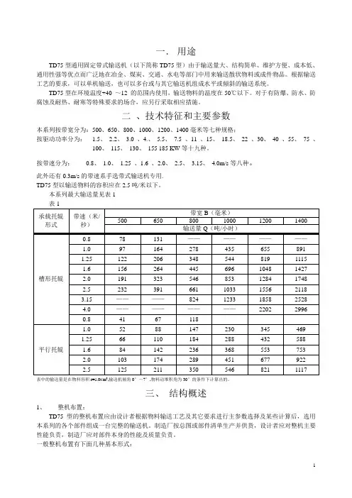
一.用途TD75型通用固定带式输送机(以下简称TD75型)由于输送量大、结构简单、维护方便、成本低、通用性强等优点而广泛地在冶金、煤炭、交通、水电等部门中用来输送散状物料或成件物品。
根据输送工艺的要求,可以单机输送,也可以多台或与其它输送机组成水平或倾斜的输送系统。
TD75型在环境温度+40 ~12 的范围内使用,输送物料的温度在50℃以下。
对于有防爆、防水、防腐蚀及耐热、耐寒等特殊要求的场合,应另行采取相应措施。
二、技术特征和主要参数本系列按带宽分为:500、650、800、1000、1200、1400毫米等七种规格;按驱动功率分为: 1.5、2.2、3.0 、4.、5.5、7.5 、11 、15、18.5、22 、30、40 、55、75 、100、115、130、155 185 KW等十九种。
按带速分为:0.8、1.0、 1.25 、1.6 、2.0、2.5、 3.15、4.0m/s等八种。
此外还有0.3m/s的带速系手选带式输送机专用.TD75型以输送物料的容积应在2.5吨/米以下。
本系列最大输送量见表1表中的输送量是在物料容积r=1.0t/m3,输送机倾角0°~7°,物料动堆积角为30°的条件下计算出的。
三、结构概述1、整机布置:TD75型的整机布置应由设计者根据物料输送工艺及其它要求进行主参数选择及某些计算后,选用本系列的各个部件组成一台完整的输送机。
制造厂按总图或部件清单生产并供货,设计者应对整机主要性能负责,制造厂应对部件本身的性能及质量负责。
一般整机布置有下面几种基本形式:图1水平输送机图2倾斜输送机图3带凸弧段输送机图4带凹弧段输送机图5带凸弧段输送机2、输送带:是曳引和承载物料的主要部件,TD75型采用普通型橡胶输送带和塑料输送带两种。
输送带的接头可采用机械卡或硫化连接。
采用机械卡连接时带强将由于接头强度的降低面降值使用此点对整芯塑料带尤为显著。

W Z B Q-6型微机监控保护装置(磁力启动器)产品使用说明书中国电光防爆电气有限公司2004年2月目录前言1、概述1 2.结构特征与工作原理1 3.技术特征2 4.按键及用户界面说明4 5.操作程序136、维护147、贮存、运输148、开箱检查149、定货须知1410、附录A14附录B15 11、附图15前言欢迎使用QJZ系列矿用隔爆兼本质安全型智能化真空电磁起动器。
本说明书介绍了该起动器的的结构和技术特征,以及应用范围、安装接线、操作维护等方面的内容。
本起动器的操作务必是在获得用户主管部门的授权并仔细阅读了本说明书后方可进行。
本起动器所用的保护装置的一些重要操作,如修改定值等均设有授权密码。
本说明书解释权归中国电光防爆电气有限公司开发部所有,如有疑问或本说明书未涵盖的技术问题,请向中国电光防爆电气有限公司开发部咨询。
注意:如不按本说明书的要求进行操作,则有可能造成不良后果!1、概述1.1主要用途及使用范围QJZ系列矿用隔爆兼本质安全型智能化真空电磁起动器(简称起动器),适用于含有爆炸性气体环境(甲烷、煤尘)的煤矿井下。
在交流50Hz,电压为1140V、660V或380V的供电线路中,对隔爆型三相鼠笼型交流异步电动机进行起动、停止、反转及联台等控制,并能对电动机及供电线路进行保护,控制方式可采用就地控制或远方控制,并可在停机时进行换向,以下说明以400A为例。
1.2使用环境装置应能在下列环境下正常工作:a) 海拔不超过2000米,周围环境压力为(0.8~1.1)×105Pa;b) 周围环境温度为-5℃~+40℃;c) 周围空气相对湿度不大于95%(+25℃);d) 须能防止水或其它液体浸入起动器内部;e) 无剧烈振动、颠簸以及与水平面安装斜度不超过15°。
1.3产品型号含义与类型Q J Z -□/ □(Z)智能化额定电压(V)额定电流(A)真空智能型隔爆兼本安起动器2、结构特征与工作原理2.1结构特征本开关采用准快速开门结构,结构简单合理,操作方便;采用简单的控制线路,实现开关的多功能(多用途),使开关能作为普通开关的单机、联控,便于管理和维护;本开关容量大,相对体积小,减小了电气设备的占地面积,减少了电气设备之间的连线。

For other service manuals visit our website at:/service_manuals.aspDORNER MFG. CORP .INSIDE THE USA OUTSIDE THE USA P .O. Box 20 • 975 Cottonwood Ave.TEL: 1-800-397-8664TEL: 262-367-7600Hartland, WI 53029-0020 USA FAX: 1-800-369-2440FAX: 262-367-58272100, 2200, 4100, 6200 & MPB Series Bottom Mount Drive Pack. for Heavy Load 90° Industrial 60 Hz GearmotorsInstallation, Maintenance & Parts ManualTable of ContentsIntroduction (2)Warnings − General Safety (3)Product Description (4)Specifications (4)Installation (9)Required Tools (9)Mounting (9)Preventive Maintenance and Adjustment (13)Required Tools (13)Timing Belt Tensioning (13)Timing Belt Replacement (13)Drive or Driven Pulley Replacement (14)Gear Reducer Replacement (14)Motor Replacement (16)Service Parts (18)2100, 2200, 4100, 6200 Series (All) and MPBSeries (Flat Belt) Bottom Mount Drive Package (18)MPB Series Cleated Belt Bottom MountDrive Package (20)4100 Series Adapter Package (22)Gear Motor (22)Notes (23)Return Policy (24)IntroductionUpon receipt of shipment:•Compare shipment with packing slip. Contact factory regarding discrepancies.•Inspect packages for shipping damage. Contact carrier regarding damage.•Accessories may be shipped loose. See accessory instruc-tions for installation.Dorner 2100 Series conveyors are covered by the following patent numbers: 5131529, 5174435, and corresponding patents and patent applications in other countries.Dorner 2200 and MPB Series conveyors are covered by patent number 5174435 and corresponding patents and patent applications in other countries.Dorner 4100 Series conveyors are covered by patent number 3923148 and corresponding patents and patent applications in other countries.Dorner 6200 Series conveyors are covered by patent numbers: 6685009, 5174435, 6109427 and corresponding patents and patent applications in other countries. Dorner’s Limited Warranty applies.Dorner reserves the right to make changes at any time without notice or obligation.Dorner has convenient, pre−configured kits of Key Service Parts for all conveyor products. These time saving kits are easy to order, designed for fast installation, and guarantee you will have what you need when you need it. Key Parts and Kits are marked in the Service Parts section of this manual with the Performance Parts Kits logoIMPORTANTSome illustrations may show guards removed. Do NOT operate equipment without guards.Warnings − General SafetyA WARNINGThe safety alert symbol, black triangle with white exclamation, is used to alert you to potential personal injury hazards.Climbing, sitting, walking or riding on conveyor will cause severe injury.KEEP OFF CONVEYORS.DO NOT OPERATE CONVEYORS IN AN EXPLOSIVE ENVIRONMENT.A WARNINGExposed moving parts can cause severe injury.LOCK OUT POWER before removing guards or performing maintenance.A WARNINGGearmotors may be HOT.DO NOT TOUCH Gearmotors.A WARNINGExposed moving parts can cause severe injury.REPLACE ALL GUARDS BEFORE RUNNING CONVEYOR.A WARNINGDorner cannot control the physicalinstallation and application of conveyors. Taking protective measures is the responsibility of the user.When conveyors are used in conjunction with other equipment or as part of a multiple conveyor system, CHECK FOR POTENTIAL PINCH POINTS and other mechanical hazards before system start-up.A WARNINGMPB Series Conveyors are not reversible. Reversing creates pinch points which can cause severe injury.DO NOT REVERSE MPB SERIES CONVEYORS.Product DescriptionRefer to Figure 1 for typical conveyor components.Figure 1SpecificationsGearmotor Mounting Package Models:Example:A ConveyorB Mounting BracketC GearmotorD Timing Belt TensionerE CoverF Timing BeltG Drive Pulley HDriven PulleyABCDEHFGSpecificationsTable 1: Gearmotor SpecificationsTable 2: Belt Speeds for Heavy Load Fixed Speed 90° 60 Hz Gearmotors on 2100, 2200 (Gang Drive), 4100 and 6200 Series Conveyors(vp) = voltage and phase:11 = 115 V , 1-phase 23 = 230V , 3-phase (n) = reversing capability:N = no reversing switchR = with reversing switch (115V , 1 phase only)Single PhaseThree PhaseDC Variable SpeedVFD Variable SpeedOutput Power 0.50 hp (0.37 kw)Input Voltage 115 VAC 208– 230 / 460 VAC 90 VDC 230 VAC Input Frequency 60 Hz N/A10 – 60 Hz Input Current 7.4 Amperes2.1 – 2/ 1 Amperes 5.0 Amperes 1.6 AmperesMotor RPM1725 25001725Gearmotor Ratios 5:1, 10:1, 20:1, 40:1, 60:1Frame Size NEMA 56CMotor TypeT otally enclosed, Fan-cooledGearmotorsBelt Speed DrivePulley Driven Pulley Part NumberGear RatioRPMIn-lbN-m Ft/minM/min32M060HS4(vp)F(n) 60:129 270 30.5 6 1.7223232M060HS4(vp)F(n) 60:129 27030.58 2.4 323232M060HS4(vp)F(n) 60:1 29 270 30.5 12 3.7 483232M040HS4(vp)F(n) 40:1 43 247 27.912 3.7 32 3232M040HS4(vp)F(n) 40:1 43247 27.9 18 5.5 48 3232M020HS4(vp)F(n)20:1 8690 10.2257.6 323232M020HS4(vp)F(n) 20:1 8690 10.237 11.3 48 3232M010HS4(vp)F(n) 10:1 173 45 5.1 49 14.9 323232M010HS4(vp)F(n)10:1 173 45 5.1 74 22.6483232M005HS4(vp)F(n)5:1 345 25 2.8 9930.2 32 3232M005HS4(vp)F(n)5:1 34525 2.8148 45.148 3232M005HS4(vp)F(n) 5:1 34525 2.8169 51.548 2832M005HS4(vp)F(n)5:134525 2.8197 60.044 2232M005HS4(vp)F(n) 5:1 34525 2.8215 65.5482232M005HS4(vp)F(n)5:1345252.8249 75.948 19SpecificationsTable 3: Belt Speeds for Heavy Load Fixed Speed 90° 60 Hz Gearmotors on 2200 Series Conveyors (Excluding Gang Drive)(vp) = voltage and phase:11 = 115 V , 1-phase 23 = 230V , 3-phase(n) = reversing capability:N = no reversing switchR = with reversing switch (115V , 1 phase only)Table 4: Belt Speeds for Heavy Load Fixed Speed 90° 60 Hz Gearmotors onMPB Series Conveyors(vp) = voltage and phase 11 = 115 V , 1-phase 23 = 230V , 3-phase (n) = reversing capability N = no reversing switchR = with reversing switch (115V , 1 phase only)GearmotorsBelt Speed DrivePulleyDriven Pulley Part NumberGear RatioRPMIn-lbN-mFt/minM/min32M060HS4(vp)F(n) 60:1 29270 30.5 6 1.7 193232M060HS4(vp)F(n) 60:1 29 270 30.5 10 3.0 282832M040HS4(vp)F(n) 40:1 43 247 27.9 15 4.6 282832M060HS4(vp)F(n) 60:1 29 270 30.5 16 4.9 44 2832M040HS4(vp)F(n)40:14324727.924 7.3 442832M020HS4(vp)F(n) 20:186 90 10.2 309.1 28 2832M020HS4(vp)F(n) 20:1 8690 10.2 4814.6 44 2832M010HS4(vp)F(n) 10:1 173 145 5.1 6118.6 282832M010HS4(vp)F(n) 10:1 173 45 5.195 29.0 44 2832M010HS4(vp)F(n) 10:1173455.1104 31.7482832M005HS4(vp)F(n) 5:1345 25 2.8 121 36.928 2832M005HS4(vp)F(n) 5:1 345 25 2.8 13842.1 32 2832M005HS4(vp)F(n) 5:1345252.8176 53.6 32 2232M005HS4(vp)F(n)5:134525 2.8208 63.4 482832M005HS4(vp)F(n)5:1 34525 2.8 24273.8 44 2232M005HS4(vp)F(n)5:1345252.8264 80.54822GearmotorsBelt Speed Drive PulleyDriven Pulley Part NumberGear RatioRPMIn-lbN-mFt/minM/min32M060HS4(vp)F(n) 60:1 29 270 30.5 13 4.0 223232M060HS4(vp)F(n) 60:1 29 270 30.5 20 6.0 282832M040HS4(vp)F(n) 40:1 43 247 27.9 29 8.9 282832M040HS4(vp)F(n) 40:1 43 24727.9 44 13.4 48 3232M020HS4(vp)F(n) 20:1 8690 10.2 59 17.9 28 28SpecificationsTable 5: Belt Speeds for Heavy Load Variable Speed 90° VFD Gearmotors on 2100, 4100 and 6200 Series Conveyors* At 60 HzTable 6: Belt Speeds for Heavy Load Variable Speed 90° VFD Gearmotors on2200 Series Conveyors (Excluding Gang Drive)Table 7: Belt Speeds for Heavy Load Variable Speed 90° VFD Gearmotors onMPB Series Conveyors* At 60 HzGearmotorsBelt Speed DrivePulley Driven Pulley Part Number Gear RatioRPMIn-lbN-m Ft/minM/min 32M060HS423EN 60:1 29 22635.50.6−5.6 0.2−1.7223232M060HS423EN 60:1 29 22635.5 0.8−8.20.3−2.532 3232M040HS423EN 40:1 43 247 27.91.2−12 0.4−3.8282832M020HS423EN 20:1 86 24827.92.5−25 0.8−7.5323232M010HS423EN 10:1 173 15617.64.9−49 1.5−15323232M005HS423EN 5:1 345 819.1 9.9−99 3−3032 3232M005HS423EN 5:1 345 81 9.1 14−148 4.5−45483232M005HS423EN 5:1345 58 6.5 19−197 6−6044 2232M005HS423EN5:1 345586.524−249 7.6−76 4819GearmotorsBelt Speed DrivePulley Driven Pulley Part Number Gear RatioRPMIn-lbN-m Ft/minM/min32M060HS423EN 60:1 29 27030.50.6−6 0.2−1.8 193232M060HS423EN 60:1 29 27030.51−10 0.3−3.1 282832M040HS423EN 40:1 43 24727.9 1.5−15 0.5−4.628 2832M020HS423EN 20:1 86 16718.93−300.9−9.2282832M010HS423EN 10:1 173115136−60 1.8−18282832M010HS423EN 10:1 1731151310−104 3.2−32482832M005HS423EN 5:1 345 58 6.512−121 3.7−37282832M005HS423EN5:1 345 58 6.526−264 8.1−814822GearmotorsBelt Speed Drive Pulley Driven Pulley Part Number Gear RatioRPM In-lb N-m Ft/min M/min 32M060HS423EN 60:12927030.5 1.3−13.4 0.4−4.1223232M060HS423EN 60:12927030.52−190.9−5.9282832M040HS423EN 40:14324727.9 2.9−290.9−8.9282832M020HS423EN 20:18616718.9 5.9−59 1.8−18282832M010HS423EN 10:11731151311−117 3.6−36282832M010HS423EN 10:11731151317−175 5.4−54483232M005HS423EN5:1345586.523−2347.1−712828SpecificationsTable 8: Belt Speeds for Heavy Load Variable Speed 90° DC Gearmotors on 2100, 2200 (Gang Drive), 4100 and 6200 Series ConveyorsTable 9: Belt Speeds for Heavy Load Variable Speed 90° DC Gearmotors on 2200 Series Conveyors (Excluding Gang Drive)Table 10: Belt Speeds for Heavy Load Variable Speed 90° DC Gearmotors on MPB Series Conveyors* = Cleated and Sidewall Cleated belts operate at a maximum of 150 Ft/min (45.7 m/min)GearmotorsBelt Speed Drive Pulley Driven Pulley Part Number Gear RatioRPM In-lb N-m Ft/min M/min 32M060PSD3DEN 60:14227030.5 1.0−8.20.3−2.5223232M060PSD3DEN 60:14227030.5 1.4−120.4−3.6323232M040PSD3DEN 40:16321524.3 2.1−180.7−5.4323232M020PSD3DEN 20:11259010.2 4.3−36 1.3−11323232M010PSD3DEN 10:1250728.19−71 2.6−22323232M005PSD3DEN 5:150025 2.817−143 5.2−43323232M005PSD3DEN 5:150025 2.826−2147.8−65483232M005PSD3DEN5:1500252.829−2459.0−754828GearmotorsBelt Speed Drive Pulley Driven Pulley Part Number Gear RatioRPM In-lb N-m Ft/min M/min 32M060PSD3DEN 60:14227030.5 1.8−140.5−4.5282832M040PSD3DEN 40:16321524.3 2.6−220.8−6.7282832M060PSD3DEN 60:14227030.5 2.8−230.8−7442832M020PSD3DEN 20:11259010.2 5.3−44 1.6−13282832M010PSD3DEN 10:1250728.110−88 3.2−27282832M005PSD3DEN 5:150025 2.817−1385−42442832M005PSD3DEN 5:150025 2.821−176 6.4−54282832M005PSD3DEN5:1500252.833−27610−844428GearmotorsBelt Speed Drive Pulley Driven Pulley Part Number Gear RatioRPM In-lb N-m Ft/min M/min 32M060PSD3DEN 60:14227030.5 2.3−190.7−5.9223232M060PSD3DEN 60:14227030.5 3.4−281−8.6282832M040PSD3DEN 40:16321524.3 5.1−42 1.6−12.9282832M060PSD3DEN 60:14227030.5 5.3−44 1.6−13442832M020PSD3DEN 20:11259010.210−853−26282832M020PSD3DEN 20:11259010.215−127 4.7−39483232M010PSD3DEN 10:1250728.120−1706−52282832M010PSD3DEN10:1250728.131−2559−774832NOTEFor belt speed other than those listed, contact factory for details.InstallationRequired Tools •Hex key wrenches:2 mm, 2.5 mm,3 mm, 5 mm •Torque wrench MountingInstallation Component List:1.Typical components (Figure 2)Figure2Figure3A WARNINGExposed moving parts can cause severeinjury.LOCK OUT POWER before removing guardsor performing maintenance.A WARNINGMPB Series Conveyors are not reversible.Reversing creates pinch points which cancause severe injury.DO NOT REVERSE MPB SERIESCONVEYORS.I Bottom Mount AssemblyJ Drive PulleyK CoverL M4 Socket Head Screws (4x)M Driven PulleyN KeyO Timing BeltP M6 Socket Head Screws (2x)Q M6 Socket−Head Screws & Hard Washers (4x)R End Support BracketS Hex Support Posts (2x)T Gearhead/Conveyor Support PlateU Support Plate SpacerV M6 Socket Head Screws (2x)W M6 Socket Head Screws (2x)NOTE2100, 2200, MPB and 6200 2” & 3” (51mm &76mm) and 4100 1” through 6” (25mm –152mm) conveyors do not include (Figure2,item R through W).NOTEGearmotor may be operated in positions 1 &3 (Figure 3).OIMPJKLNQRT UWSVQInstallation2.If required, change gearmotor position by removing four screws (Figure 4,item X) from bottom mount assembly and two screws (Figure 5,item Y) from gear reducer support. Rotate gearmotor to other position and install screws. Tighten screws to 103 in-lb (12 Nm).Figure 4Figure 53.For your reference, the following figures show theattachment area of complete mounting packages for the various conveyor series.2200 Series Figure66200 SeriesFigure 74100 Series Figure 82100 SeriesFigure 9MPB Series Figure10XXYNOTE6200 conveyor shown, other Series similar.Installation4.Locate drive output shaft (Figure 11,item Z) and remove two screws (AA).Figure 11For 2100, 2200 and 6200 − 2” & 3” (51mm & 76mm) wide conveyors and 4100 − 1” through 6” (25mm – 152mm) wide conveyors:5.Attach bottom mount assembly (Figure 12,item I) with screws (P). Tighten to 80 in-lb (9 Nm). Proceed to step 10.Figure 12For 2100, 2200, 6200 and MPB − 4” (102mm) and wider conveyors and 4100 − 8” (203mm) and wider conveyors: 6.On side opposite drive output shaft, remove two screws (Figure 13,item AB).Figure 137.Attach bottom mount assembly (Figure 12,item I) with two screws (P). Tighten to 80 in-lb (9 Nm).8.Install hex support posts (Figure 14,item S). Tighten posts to 80 in-lb (9 Nm).Figure 149.Install spacer (Figure 15,item U) (2100 & 6200 Only) and gearhead/conveyor support plate (T) with screws (V). Install end support bracket (R) with screws (W). Tighten screws (V & W) to 80 in-lb (9 Nm).Figure 15NOTERefer to Figure 6 through Figure 10 whiledoing step 7.AAZIPADABA WARNINGDrive shaft keyway may be sharp.HANDLE WITH CARE.SURTVWInstallation10.Install key (Figure 16,item N).Figure 1611.Wrap timing belt (O) around driven pulley (M) anddrive pulley (J). Install driven pulley (M) onto conveyor shaft.12.Remove cam bearing and spacer (Figure 12,item AD).Place cam bearing and spacer (Figure 17,item AD) next to driven pulley (M). Ensure flanges of driven pulley are aligned with cam bearing. Tighten driven pulley set screws (AA). This will allow for proper belt alignment while conveyor is in use. Install cam bearing and spacer (AD).Figure 1713.Depending on direction of conveyor belt travel (1 or 2of Figure 18), position belt tensioner (AE) as shown. Tension belt to obtain 0.125¨ (3 mm) deflection for 1.0 lb (456 grams) of force at belt mid-point (AF). Tighten tensioner screw to 103 in-lb (12 Nm).Figure 1814.Install cover (Figure 19,item K) with four screws (L).Tighten to 35 in-lb (4 Nm).Figure 1915.Mount assembly to support structure with four hardwashers and screws (Figure 20,item Q). Tighten to 80 in-lb (9 Nm).Figure 20NOJMAAADM1AFAF2KLQPreventive Maintenance and AdjustmentRequired Tools•Hex key wrenches:2 mm, 2.5 mm,3 mm, 5 mm•Adjustable wrench (for hexagon head screws)•Torque wrenchTiming Belt Tensioning1.Remove four (4) screws (Figure 19,item L) and remove cover (K).2.Loosen tensioner (Figure 21,item AE).Figure 213.Depending on direction of conveyor belt travel (1 or 2 of Figure 18), position belt tensioner (AE) as shown. Tension belt to obtain 0.125¨ (3 mm) deflection for 1.0 lb (456 grams) of force at belt mid-point (AF). Tighten tensioner screw to 103 in-lb (12 Nm).4.Install cover (Figure 19,item K) with four (4) screws (L). Tighten to 35 in-lb (4 Nm).Timing Belt Replacement1.Remove four (4) screws (Figure 19,item L) and remove cover (K).2.Loosen tensioner (Figure 21,item AE).3.Remove timing belt (Figure 22,item O).Figure 224.Install new timing belt.5.Depending on direction of conveyor belt travel (1 or 2 of Figure 18), position belt tensioner (AE) as shown. Tension belt to obtain 0.125¨ (3 mm) deflection for 1.0 lb (456 grams) of force at belt mid-point (AF). Tighten tensioner screw to 103 in-lb (12 Nm).6.Install cover (Figure 19,item K) with four (4) screws (L). Tighten to 35 in-lb (4 Nm).A WARNINGExposed moving parts can cause severe injury.LOCK OUT POWER before removing guards or performing maintenance.AE OA WARNINGExposed moving parts can cause severe injury.LOCK OUT POWER before removing guards or performing maintenance.NOTEIf timing belt does not slide over pulley flange, loosen driven pulley set screws (Figure22,item AG) and remove pulley with belt (O). For re-installation, see steps 11 and Figure 16 on page 12.AGOPreventive Maintenance and AdjustmentDrive or Driven Pulley Replacementplete steps 1 through 3 of “Timing BeltReplacement” section on page 13.2.Loosen set screws and remove drive or driven pulley.3.Complete steps 11 through 14 of “Installation” section on page 12.Gear Reducer Replacement1.Remove four (4) screws (Figure 19,item L) and remove cover (K).2.Loosen tensioner (Figure 21,item AE).3.Loosen drive pulley set screws (Figure 23,item AG). Remove drive pulley (J) and timing belt (O).Figure 234.Remove screws (Figure 24,item V & W) and remove support bracket (R), support plate (T) and spacer (U).Figure 245.Remove hex support posts (Figure 25,item S).Figure 25A WARNINGExposed moving parts can cause severe injury.LOCK OUT POWER before removing guards or performing maintenance.NOTEIf drive pulley (Figure 23,item J) is replaced, wrap timing belt around drive pulley and complete step 3.A WARNINGExposed moving parts can cause severe injury.LOCK OUT POWER before removing guards or performing maintenance.OJAGURTVWSPreventive Maintenance and Adjustment 6.Remove two (2) bracket screws (Figure 26,item AL)and remove bracket (AM).Figure267.Remove four (4) gear reducer mounting screws (Figure27,item AN). Remove gearmotor.Figure278.Remove four screws (Figure 28,item AO). Detachmotor (AP) from gear reducer (AQ). Retain motor output shaft key (AR).Figure289.Remove two (2) screws (AS) and detach output shaftcover (AT).10.Remove gear reducer output shaft key (AU).11.Loosen six (6) set screws (Figure 29,item A V). Removedrive shaft (AW) and key (AX).Figure29AMALANAPAQATA SAOAOAUARAV AWAXPreventive Maintenance and Adjustment12.Apply grease (Figure 30,item AY) to shaft.Figure 3013.Replace the original shaft components into new gearreducer (see Figure 29). Tighten set screws (A V) to 26 in-lb (3 Nm).14.With key (Figure 28,item AR) in keyway, slide motor(AP) and gear reducer (AQ) together. Install screws (AO) and tighten.15.Reverse steps 4 through 7 beginning on page 14.plete steps 11 through 15 of “Installation” sectionon page 12.Motor Replacement1.For single phase motor, unplug power cord from outlet.2.For three phase and VFD variable speed motor:a.Loosen terminal box screws (Figure 31,item AZ) and remove cover (BA).Figure 31b.Record wire colors on terminals 1, 2 and 3. Loosen wire nuts and remove wires 1, 2 and 3.c.Loosen cord grip and remove cord.3.For DC variable speed motor, unplug motor cord at disconnect (Figure 32,item BB).Figure 32IMPORTANTBe extremely careful when coupling motor to gear reducer. Avoid misalignment and forcing the connection causing possible permanent gear reducer seal damage.NOTEDrive pulley (Figure 23,item J) is removed. Wrap timing belt around drive pulley and complete step 16.A WARNINGExposed moving parts can cause severe injury.LOCK OUT POWER before removing guards or performing maintenance.AYHazardous voltage will cause severe injury or death.LOCKOUT POWER BEFORE before wiring.AZBABBPreventive Maintenance and Adjustment4.Remove four screws (Figure 33,item AO). Detach motor (AP) from gear reducer (AQ). Retain motor output shaft key (AR).Figure 335.With key (Figure 34,item AR) in keyway, slide motor and gear reducer together. Install screws (AO) and tighten.Figure 346.Replace wiring:•For a single phase motor, reverse step 1 on page 16.•For a three phase and VFD variable speed motor, reverse step 2 on page 16.•For a DC variable speed motor, reverse step 3 on page 16.IMPORTANTBe extremely careful when coupling motor to gear reducer. Avoid misalignment and forcing the connection causing possible permanent gear reducer seal damage.APAOAQARARAOService PartsNOTEFor replacement parts other than those shown in this section, contact an authorized Dorner Service Center or the factory. Key Service Parts and Kits are identified by the Performance Parts Kits logo . Dorner recommends keeping these parts on hand.2100, 2200, 4100, 6200 Series (All) and MPB Series (Flat Belt) Bottom Mount Drive PackageService PartsItem Part NumberDescription1 202390MNut2920625M Socket Head Screw M6x25mm (2100 & 2200)920616M Socket Head Screw M6x16mm (4100)920630MSocket Head Screw M6x30mm (6200)3450375MCover Mounting Bracket4450445 Spacer 5802−046 Bearing 6920845M Socket Head Screw M8x45mm 7920410M Socket Head Screw M4x10mm 8920693M Socket Low Head Screw M6x16mm 9450443M Grove Mounting Plate 10980422M Square Key 4mm x 22mm 11912−084Square Key, 0.188 x 1.5”12450444M Grove Output Shaft 12mm 13300139Drive −Bearing Shaft Cover 14920616M Socket Head Screw M6x16mm 15920608M Socket Head Screw M6x8mm 16605279P Hard Washer17450441M Gearhead Support Bracket 184533WWM Gearhead Support Hex Post 19450440M End Support Bracket20450442M Gearhead/Conveyor Support Plate 697869MGearhead/Conveyor Support Plate w/Spacer (4100 Only)21450027M Drive Spacer [2100 − 4”−24” (102mm − 610mm) and All 6200]22807−952Grooved Pin [2100 − 4”−24” (102mm −610mm) and All 6200]23920620MSocket Head Screw M6x20mm24450376M Drive Guard 25807−226 Snap −out Plastic Plug 26920406M Socket Head Screw M4x6mm 27980422M Square Key 4mm x 22mm912−053 Square Key, 0.125 x 0.75” [4100 − 1”(25mm) Conveyor Only]28814-104 Timing Belt, 15mm W x 450mm L 814-105 Timing Belt, 15mm W x 460mm L 814-065 Timing Belt, 15mm W x 475mm L 814-112Timing Belt, 15mm W x 495mm L 814-101 Timing Belt, 15mm W x 500mm L 814-108 Timing Belt, 15mm W x 520mm L 814-064 Timing Belt, 15mm W x 535mm L 814-099Timing Belt, 15mm W x 565mm L 29450365MP Driven Pulley, 19Tooth, 12mm bore 450366MP Driven Pulley, 22Tooth, 12mm bore 450367MP Driven Pulley, 28Tooth, 12mm bore 450368MPDriven Pulley, 32Tooth, 12mm bore 30450365MP Drive Pulley, 19Tooth, 12mm bore 450366MP Drive Pulley, 22Tooth, 12mm bore 450367MP Drive Pulley, 28Tooth, 12mm bore 450368MP Drive Pulley, 32Tooth, 12mm bore 450369MP Drive Pulley, 44Tooth, 12mm bore 450370MPDrive Pulley, 48Tooth, 12mm boreWW = Conveyor width ref.: 01, 02, 03, 04, 06, 08, 10, 12, 18, 21, 24Item Part Number DescriptionService PartsMPB Series Cleated Belt Bottom Mount Drive Package27851-279 Rev. I21Dorner Mfg. Corp.2100, 2200, 4100, 6200 & MPB Series Bottom Mount Drive Pack. for Heavy Load 90° Industrial 60 Hz Gearmotors Service PartsItem Part Number Description1202390M Nut2920692M Socket Low Head Screw M6 x 12mm 3920625M Socket Head Screw M6x25mm 4802−046Bearing 5807−1133Washer6920845M Socket Head Screw M8x45mm 7450445Spacer8243402Cover Mounting Angle9920693M Socket Low Head Screw M6x16mm 10243401Mounting Plate11920416M Socket Head Screw M4x16mm 12980422M Square Key 4mm x 22mm 13912−084Square Key, 0.188 x 1.5”14450444M Grove Output Shaft 12mm 15300139Drive −Bearing Shaft Cover 16920616M Socket Head Screw M6x16mm 17605279P Hard Washer18450441M Gearhead Support Bracket 194533WWM Gearhead Support Hex Post 20450440MEnd Support Bracket21243403Gearhead/Conveyor Support Plate 22920620M Socket Head Screw M6x20mm 23300871M Drive Cover24920408M Socket Head Screw M4x8mm 25450367MP Driven Pulley, 28T ooth, 12mm bore 450368MP Driven Pulley, 32T ooth, 12mm bore 26450366MP Drive Pulley, 22Tooth, 12mm bore 450367MP Driven Pulley, 28T ooth, 12mm bore 450369MP Drive Pulley, 44Tooth, 12mm bore 450370MP Drive Pulley, 48Tooth, 12mm bore 27814-101Timing Belt, 15mm W x 500mm L 814-108Timing Belt, 15mm W x 520mm L 814-064Timing Belt, 15mm W x 535mm L 814-099Timing Belt, 15mm W x 565mm L 814-109Timing Belt, 15mm W x 580mm L 814-115Timing Belt, 15mm W x 600mm L 814-110Timing Belt, 15mm W x 615mm LWW = Conveyor width ref.: 04, 06, 12, 18, 24Item Part Number DescriptionDorner Mfg. Corp.22851-279 Rev. I2100, 2200, 4100, 6200 & MPB Series Bottom Mount Drive Pack. for Heavy Load 90° Industrial 60 Hz Gearmotors Service Parts4100 Series Adapter Package Gear MotorItem Part No.Part Description1609486Mounting Block 1” (25mm)609487Mounting Block 2” (51mm)609488Mounting Block 3” (76mm)609479Mounting Block 4” (102mm)609480Mounting Block 5” (127mm)609481Mounting Block 6” (152mm)609482Mounting Block 7” (178mm)609483Mounting Block 8” (203mm)609484Mounting Block 10” (254mm)609485Mounting Block 12” (305mm)2613602P Bolt & Flat Washer Assembly 3450374Drive Adapter Plate 4910−126Hex Nut with Lock Washer 5930612MFlat Head Screw M6 x 12mmItem Part No.Part Description162MH411FN Motor, 0.5 hp (0.37 Kw) 115/230 Volts,60 Hz, 1-Phase, non −reversing 62MH411FR Motor, 0.5 hp (0.37 Kw) 115/230 Volts, 60 Hz, 1-Phase, reversing62MHD9DEN Motor, 0.5 hp (0.37 Kw) 90 Volts DC 32MS423EN Motor, 0.5 hp (0.37 Kw) 230V , 10– 60Hz, Inverter Duty, 3 Phase62MH423Motor, 0.5 hp (0.37 Kw) 208−230/460 Volts, 60 Hz, 3-Phase 232M005HS Gear Reducer, 5:1, 56C 32M010HS Gear Reducer, 10:1, 56C 32M020HS Gear Reducer, 20:1, 56C 32M040HS Gear Reducer, 40:1, 56C 32M060HSGear Reducer, 60:1, 56C21Notes2100, 2200, 4100, 6200 & MPB Series Bottom Mount Drive Pack. for Heavy Load 90° Industrial 60 Hz Gearmotors 851-279 Rev. I23Dorner Mfg. Corp.Dorner Mfg. Corp. reserves the right to change or discontinue products without notice. Allproducts and services are covered in accordance with our standard warranty. All rights reserved. © Dorner Mfg. Corp. 2010DORNER MFG. CORP.975 Cottonwood Ave., PO Box 20Hartland, WI 53029-0020 USATEL 1-800-397-8664 (USA)FAX 1-800-369-2440 (USA)Internet: Outside the USA:TEL 1-262-367-7600FAX 1-262-367-5827Return PolicyReturns must have prior written factory authorization or they will not be accepted. Items that are returned to Dorner without authorization will not be credited nor returned to the original sender. When calling for authorization, please have the following information ready for the Dorner factory representative or your local distributor:1. Name and address of customer.2. Dorner part number(s) of item(s) being returned.3. Reason for return.4. Customer's original order number used when ordering the item(s).5. Dorner or distributor invoice number (if available, part serial number).A representative will discuss action to be taken on the returned items and provide a Returned Goods Authorization (RMA)number for reference. RMA will automatically close 30 days after being issued. To get credit, items must be new and undamaged. There will be a return charge on all items returned for credit, where Dorner was not at fault. It is the customer’s responsibility to prevent damage during return shipping. Damaged or modified items will not be accepted. The customer is responsible for return freight.Conveyors and conveyor accessoriesStandard catalog conveyors 30%MPB, 7200, 7300 Series, cleated and specialty belt50%AquaGard & AquaPruf Series conveyors non-returnable itemsEngineered to order products case by caseDrives and accessories30%Sanitary stand supports non-returnable itemsPartsStandard stock parts30%Plastic chain, cleated and specialty belts non-returnable itemsReturns will not be accepted after 60 days from original invoice date. The return charge covers inspection, cleaning, disassembly, disposal and reissuing of components to inventory. If a replacement is needed prior to evaluation of returned item, a purchase order must be issued. Credit (if any) is issued only after return and evaluation is complete.Dorner has representatives throughout the world. Contact Dorner for the name of your local representative. Our Customer Service Team will gladly help with your questions on Dorner products.For a copy of Dorner's Warranty, contact factory, distributor, service center or visit our website at .For replacement parts, contact an authorized Dorner Service Center or the factory.851-279 Rev. I Printed in U.S.A.。

前言感谢您购买Siemens Energy Subsea 产品。
本文档涵盖DigiTRON 连接器产品系列的保护、存储、运输、开箱、部署和维护相关信息。
重要信息请在使用前仔细阅读请妥善保存,以供日后参考修订摘要本页记录了整个文件的修订状态及其发行授权。
版权所有 © 2020 Siemens Energy Subsea Connectors(Siemens Energy plc 的一个分部),Subsea Excellence Centre, Ulverston, Cumbria, LA12 9EE, England。
版本编制人日期批准人发布日期受影响的页面/备注1 R Wyatt 2020 年 11月 6 日M. Tucker 2020 年 11月 6 日第一期。
[取代已作废的 IOM 10071599]目录1本手册涵盖的产品 (6)2基本信息和快速参考 (7)2.1产品概览 (7)2.2产品规格和认证 (8)2.3联系信息和反馈 (9)2.4产品建议标签 (9)2.5产品标志 (10)2.6产品示例 (10)3产品安全 (13)3.1与操作相关的警告 (13)3.2预期用途 (13)3.3一般安全信息 (14)3.4相关文档 (17)3.5危害健康物质管制条例 (COSHH) (18)4缩写 (19)5规格 (20)5.1连接器规格 (20)6准备产品的使用或储存 (21)6.1产品保护和包装 (21)6.2开箱 (22)6.3存储、保护和使用寿命终止 (22)7安装和装配 (24)7.1阴极保护 (24)7.2穿板(密封法兰)ROV 插座连接器 (24)7.3兼容的法兰安装 ROV 插座连接器 (25)7.4停车插座 (26)7.5测试连接器 (27)8正常运行和故障状态期间的用户信息 (28)8.1视觉信号 (28)8.2正常和故障/危险操作 (28)8.3故障排除 (28)9产品操作与维护 (29)9.1安全注意事项 (29)9.2产品维护和保养 (29)9.3产品保护;端盖和环回连接器 (29)9.4带电插拔 (30)9.5去除海洋微生物和钙沉积物 (30)9.6产品测试 (31)9.7插接产品前的检查 (32)9.8ROV 连接器的插拔 (32)9.9连接器的手动插拔 (34)10客户意见/反馈 (38)表格表 1 与 DigiTRON 产品系列相关的其他安装、操作和维护手册列表 (6)表 2 DigiTRONf 产品系列标识 (7)表 3 DigiTRONf 产品规格和认证 (8)表 4 DigiTRON 产品联系信息 (9)表 5 产品故障排除联系信息 (28)图示图 1 产品建议标签 (9)图 2 DigiTRONf 产品上的产品标志 (10)图 3 典型穿板式安装(密封法兰)连接器,带干式插接连接器选件 (10)图 4 软管端接的典型连接器 (11)图 5 典型水下保护盖 (11)图 6 飞线插头的典型停放位置 (12)图 7 典型测试线束 (12)图 8 可接受的装运包装 (21)图 9 不可接受的包装和存储 (21)图 10 密封式隔板插座连接器 (25)图 11 ROV 兼容安装插座 (25)图 12 符合ROV 的安装截面图,以识别安装和部件 (26)图 13 典型停放插座 (26)图 14 运输保护盖(左)和保护盖(右) (29)图 15 允许的喷水清洗 (31)图 16 对齐标记和唇形密封配合指示器 (33)图 17 手动插拔工具,零件号 S1U10509147 (35)图 18 插拔杆臂枢轴销位置 (35)图 19 插头安装至插接工具 (36)图 20 插座安装至插接工具 (36)图 21 插接操作 (37)图 22 拔出操作 (37)1 本手册涵盖的产品本手册涵盖有关 DigiTRON f(光纤)单连接器的信息,包括其光学和机械规格。

高压成套元器件High-voltage Components GLOBALElectrical SystemsD X N-Q德勒控股集团德勒控股集团德勒控股集团德勒控股集团L-3户内高压带电显示器JSY-Ⅰ注:反向电磁锁要定做CG5-10Q/95×130(130.140.145.150)4-M10VS1-3150A 触臂材料:紫铜硫化处理(注:该型触臂为加长型,适用于大电流隔离车)VS1-4000A 触臂材料:紫铜硫化处理E ECL2601488105240330962425C10-9X19C外形及安装尺寸型号规格L E C JN15-12/31.5-150JN15-12/31.5-210JN15-12/31.5-27553565581015021027539651664627527575810185软连接两孔距L=400mm20-9X19969696主轴母线解触头4060404-φ113271101736462025170701602303558858240R 277外形及安装尺寸主要技术参数外型及安装尺寸使用场所低压使用场所电容使用场所配电(S)注:1、虚线框为计数器显示部分的外形尺寸,此图为柜门正面图;2、只需在柜门上开三个安装孔(3-Φ3.4)和一个信号线插件孔Φ21;3、将计数器背面的三个安装孔与柜门上开的三个安装装孔一一对应,然后在柜门内侧用自攻螺丝拧紧,信号连接线插头通过Φ21的孔插入计数器背面的信号线插件孔中。
TBP系列三相四相组合式过电压保护器(组合式避雷器)6KV、10KV、35KV接线端子示意图24.724132LL10-W 安装支架外形尺寸138.325050138.320LL10-W 灯体LL10-W 安装支架装配好的LL10-W可通过卡脚或螺钉装配。
装配时先固定安装支架,外形及安装尺寸图外形图199139118单位:mm注意:本产品需在柜门上开具尺寸为179±0.5mm 图)作为固定本产品用。

电力机车自动过分相装置地面磁性设备技术规格及安装规程目录第一节工作原理 (1)1.1工作原理 (1)(1)概述 (1)(2)主要性能 (1)(3)系统技术性能 (2)1.2 地面磁性设备组成及外形 (4)(1)信号轨枕 (6)(2)磁性感应装置 (6)(3)无碴设备防护罩及其它附件 (6)第二节技术条件参数 (7)2.1 采用技术标准 (7)2.2 应用范围 (7)2.3 工作和环境条件 (7)2.4主要技术性能参数 (8)第三节地面磁性设备的安装 (10)3.1 有碴轨道磁性设备的安装 (10)3.1.1 安装作业流程 (10)3.1.2 信号轨枕位置标示流程 (11)3.1.3 中性区段的确定 (12)3.1.4 安装距离的确定 (13)3.1.5 抽换安装 (15)3.1.6磁性装置的安装(现场组装情况下) (15)3.1.7 注意事项 (16)3.2 无碴轨道磁性设备的安装 (18)3.2.1 安装作业流程 (18)3.2.2 地面磁性设备位置标示流程 (20)3.2.3地面磁性设备螺孔位置标示注意事项 (21)3.2.4 中性区段的确定 (22)3.2.5 安装距离的确定 (22)3.2.6 高速和重载线路的安装位置要求 (25)3.2.7 注意事项 (25)第四节地面磁性设备的日常维护和定期检修 (26)4.1 巡道检查 (26)4.2 检测地面磁性设备纵向位置 (26)4.3 检测磁性装置的磁场感应强度 (27)4.4 需要更换或修复情况 (28)4.5 避免随意移动、抽除信号轨枕 (28)第一节工作原理1.1工作原理(1)概述电力机车自动过分相地面磁性设备是基于免维护地面定位技术的车载自动过分相控制系统的地面磁性设备。
机车通过感应地面定位信号确定机车与分相点的相对位置,地面定位和机车感应信号分别采用斜对称埋设和备份接收,以保证自动过分相的安全和可靠。
(2)主要性能电力机车通过时会发出相应信号给机车,通过车载感应接收器和过分相控制装置自动完成电力机车断电过分相。
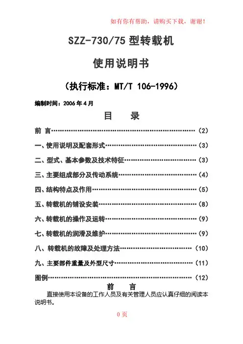
SZZ-730/75型转载机使用说明书(执行标准:MT/T 106-1996)编制时间:2006年4月目录前言 (2)一、使用说明及配套形式 (3)二、型式、基本参数及技术特征 (3)三、主要组成部分及传动系统 (4)四、结构特点及作用 (5)五、转载机的铺设安装 (8)六、转载机的操作及运转 (9)七、转载机的润滑及维护 (9)八、转载机的故障及处理方法 (10)九、主要部件重量及外型尺寸 (11)图例 (12)前言直接使用本设备的工作人员及有关管理人员应认真仔细的阅读本说明书。
本说明书将有助于您熟悉和了解正在选型或使用设备的功能及使用范围。
有助于您做出明智、经济的选择。
本说明书内容包含了有关安全操作,正确经济的使用设备的详细说明及有关建议。
认真仔细的阅读本说明书将有助于预防事故,降低维修成本节省维修时间,提高设备的可靠性,并可延长设备的使用寿命。
为保证设备安全可靠的运行,合理的组织及适当的预防措施,是十分重要的。
本说明书所定的维护周期是最大的,仅为推荐值。
应根据现场的具体情况及工作环境做进一步的调整。
应遵守安全操作规程,特别是在井下预防事故及安全运行的规定。
在安装设备的现场应备有说明书,操作中除遵守安全方面的规定外,还要遵守起重、运输、电工、钳工等方面的有关规定。
应遵守附件生产厂家相应的操作说明,如电动机、真空开关等,只允许使用合格的附件。
随机供应的备件是按正常工作状态提供的,是可以使设备处于长久的良好运行状态,在特殊情况下损坏和提前失效的零部件必须用同样的零部件更换。
由于操作人员训练不足或操作不当均可出现危险,所以只有受过良好训练的、合格的人员才允许操作设备。
在操作设备之前,请认真危险提示是使您引起对危险性的注意,否则将导致严重受伤或死警告提示是使您引起对危险性的警惕,否则将导致受伤或死亡,注意提示是使您引起对危险性的注意,否则将导致人身伤害或设备损坏。
这类危险性通常是不严重的。
但发展下去后果是可怕的,如果不采取合适的预防措施,甚至会发生致命伤害。


干式变压器安装维护使用说明书福州天宇电气股份有限公司FUZHOU TIANYU ELECTRIC CO.,LTD.1.适用范围本说明书适用于本公司生产的额定容量在20000kV A及以下,电压等级35kV及以下的无励磁调压和有载调压干式变压器。
2.使用条件2.1海拔不超过1000m,环境温度不超过40°C。
若环境温度高于40°C或海拔超过1000m时,应按GB6450的规定作适当的调整。
电源电压的波形近似于正弦波。
三相变压器所连接的电源电压近似对称。
2.2外壳防护等级有IP00、IP20、IP30等型式。
2.3冷却方式有空气自冷(AN)和强迫风冷(AF)两种。
要求变压器室必须具有良好的通风能力,每1kW损耗所需要的空气流量不小于4m^3/min。
3.产品装卸3.1装卸时严格按国家标准及装卸规程操作。
3.2装卸设备可采用起重机、汽车吊或叉车等起吊设备。
3.3产品吊装可采用以下三种方式进行。
A:同时使用变压器上的所有吊板起吊,吊升时吊索与垂线的角度不超过30°。
调整吊索的长度使吊钩正对变压器重心。
如图a。
B:若因吊高限制不能符合条件,应在包装箱底板的四角垫木处(滑木倒角处附近)挂吊索,同时保证吊索与垂线的角度不超过30°。
调整吊索的长度使吊钩正对变压器重心。
如图b。
C:带外壳的变压器,除可以采用图b所示的应用包装箱底板垫木处挂吊索起吊外,还可以采用变压器上的吊板起吊,方法是先打开包装箱顶盖,可以看到如图c所示的变压器顶窗,打开顶窗,将吊索伸入变压器外壳,如图d,并按方法A起吊。
有载调压变压器若有载开关与变压器连接在一起整体包装,仅采用变压器上的所有吊板起吊。
3.4用户应采用开箱专用工具或合适的工具(钉锤、扳手、螺丝刀等)将包装箱打开,不可用金属物或其它工具撞击包装箱,以免损坏产品。
3.5干式变压器除温控箱外一般为整体运输,温控箱按原包装固定在变压器本体包装箱内。
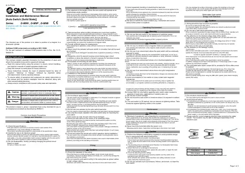
Installation and Maintenance Manual[Auto Switch (Solid State)]Series D-M9N , D-M9P , D-M9B(Complies with the basic safety principles in accordance withISO 13849)The intended use of this product is to detect a position of a magnet in a pneumatic cylinder.Validated D-M9 components according to ISO 13849:For the part numbers of validated D-M9 products refer to Doc. No. D-*S-SMQ0018.This manual contains essential information for the protection of users and others from possible injury and/or equipment damage.•Read this manual before using the product, to ensure correct handling, and read the manuals of related apparatus before use.•Keep this manual in a safe place for future reference.•These instructions indicate the level of potential hazard by label of “Caution”, “Warning” or “Danger”, followed by important safety information which must be carefully followed.•To ensure safety of personnel and equipment the safety instructions in this manual and the product catalogue must be observed, along with other relevant safety practices.•Always ensure compliance with relevant safety laws and standards.Caution Indicates a hazard with a low level of risk, which if notavoided, could result in minor or moderate injury.Warning Indicates a hazard with a medium level of risk, whichif not avoided, could result in death or serious injury.Danger Indicates a hazard with a high level of risk, which ifnot avoided, will result in death or serious injury.This product is class A, group 1 equipment that is only intended for use inan industrial environment as described by EN55011.Common Auto Switch PrecautionsDesign and SelectionWarning(1) Check the specifications.If the auto switch is used with an excessive load or used outside of thespecifications, it may cause damage or malfunction.The product cannot be guaranteed if is used outside of the specification range.(2) Caution for use in an interlock system.When an auto switch is used in an interlock system which requires high reliability,provide a double interlock system, for example a mechanical protection system, forextra safety, or by also using another switch (sensor) together with the auto switch.Check the product regularly in order to confirm normal operation.(3) Do not disassemble, modify (including changing the printed circuitboard) or repair.An injury or failure can result.Caution(1) Pay attention to the length of time the auto switch will operate at anintermediate stroke position.When an auto switch is placed at an intermediate stroke position, and a load isdriven during the time when the piston passes, the auto switch will operate, but ifthe piston speed is too great, the operating time will be shortened, and the loadmay not operate correctly.The maximum piston speed is:V [mm/s] =Auto switch operating range [mm]×1000Load operating time [ms](2) Take precautions when multiple actuators are used close together.When using two or more actuators with auto switches in close proximity to eachother, maintain a minimum separation distance of at least 40 mm. (If the separationdistance is specified for the actuator series, then use that value).The auto switches may malfunction due to magnetic field interference.Use of a magnetic screen plate (MU-S025) or commercially available magneticscreening tape can reduce the interference of magnetic fields.(3) Provide sufficient space for maintenance.When designing an application, allow sufficient clearance for maintenance andinspection.(4) Never mount the actuator with auto switch in a location that will be usedas a footrest.The product may be damaged if excessive force is applied by stepping or climbingonto it.(5) Design the circuit to prevent reverse current during open circuitconditions or when the product is forced to operate for functional checks.Reverse current can cause product damage or malfunction.(6) Precautions for mounting an auto switchWhen n number of auto switches is specified for mounting, this indicates themaximum number of auto switches based on the physical dimensions of theactuator.The detection distance varies depending on the auto switch mounting structureand the auto switch body dimensions. For this reason, the switch may not alwaysbe mounted at the required detection distance or at the required position.(7) Limitations of the detection position.There will be mounting positions or surfaces where the auto switch cannot bemounted due to physical interference (e.g. rear side of the foot bracket), dependingon the mounting conditions of the actuator.Select an auto switch after confirming that the switch mounting position does notinterfere with the mounting bracket (e.g. trunnion, reinforcement ring).Mounting and AdjustmentCaution(1) Do not drop or apply impact.The auto switch may be damaged or malfunction if it is dropped, bumped or appliedwith excessive impact (1000 m/s2 or more).(2) Observe the required tightening torque for mounting an auto switch.If an auto switch is tightened beyond the specified tightening torque, the autoswitch, mounting screws, or mounting bracket may be damaged.Tightening below the specified tightening torque will allow the auto switch to moveout of position.(3) Do not carry an actuator by the auto switch lead wire.This may cause a broken lead wire or damage to the auto switch internal elements.(4) Use only the screws installed in the auto switch body for mounting theauto switch.If other screws are used, the auto switch may be damaged.(5) Mount the auto switch at the centre of its operating range.Auto switches should be mounted so that the most sensitive position is at thecentre of the operating range.Mounting the auto switch close to the edge of its operating range (close to theborder of ON/OFF operation) may cause unstable operation.(The auto switch mounting positions shown in the actuator catalogue indicate theoptimum position at the end of stroke).Some actuator and cylinder series have their own setting methods. In such cases,follow the instructions given.(6) Check and adjust the actual auto switch operation during installation.The auto switch may not operate in the correct actuator mounting position due tothe installation environment.Also check and adjust the auto switch operation when used in intermediate strokepositions, according to the operating environment.WiringCaution(1) Check the insulation of the wiring.Check that there is no faulty wiring insulation (short circuits, faulty groundconnections, improper insulation between terminals, etc.), as this may damage theauto switch due to over current.(2) Do not route the auto switch wiring in the same place as power cablesor high voltage cables.Otherwise auto switch malfunction may result due to noise and inrush current.(3) Avoid repeatedly bending or stretching the lead wire.Broken lead wires will result if bending stresses or tensile forces are applied to thelead wires.Stress and tensile forces applied to the connection between the lead wire and autoswitch increases the possibility of disconnection.Secure the lead wire to reduce any movement in the area where the lead wireconnects with the auto switch.The standard of bending radius becomes R20 to 40 mm.(4) Be sure to confirm the load condition (e.g. connection and currentvalue) before power is supplied.Operating EnvironmentWarning(1) Do not use the auto switch in the presence of explosive gases.Auto switches are not designed with an explosion proof construction. Fire or anexplosion may result.Contact SMC for information regarding ATEX compliant products.Caution(1) Do not use in a location where magnetic fields are generated.Auto switches will malfunction or the magnets inside actuators will becomedemagnetized.(2) Do not use in an environment where the auto switch will be continuallyexposed to water.Although auto switches satisfy the IEC standard IP67 construction, do not use inapplications continually exposed to water splashes or spray. Otherwise, insulationfailure or malfunction may result.(3) Do not use in an environment where oil or chemical splashes canoccur.If auto switches are used in an environment with coolants, cleaning solvents, oils orchemicals for even a short time, they may be adversely affected by insulationfailure, malfunction due to swelling of the potting resin, or hardening of the leadwires.(4) Do not use in an environment where there are cyclic temperaturechanges.Temperature cycles other than normal temperature changes can adversely affectthe auto switch internally.(5) Avoid accumulation of iron debris or close contact with magneticsubstances.When a large amount of iron waste such as machining chips or spatter hasaccumulated, or a magnetic substance (something attracted by a magnet) isbrought into close proximity with the actuator, it may cause the auto switch tomalfunction due to a weakening of the magnetic force inside the actuator.(6) Contact SMC for information regarding auto switch water resistance,elasticity of lead wires, applications in welding sites, etc.(7) Do not use in direct sunlight.(8) Do not mount the auto switch in locations where it is exposed to radiantheat.(9) The auto switch is CE marked, but not immune to lightning strikes. Takemeasures against lightning strikes in the system.MaintenanceWarning(1) Removal of equipment, and exhausting the compressed air.When equipment is to be removed, first confirm that measures are in place toprevent losing control of the equipment or workpieces from falling, etc. Turn off thepower supply, stop the air supply and exhaust all compressed air from the system.Before restarting the equipment, confirm that measures are taken to preventsudden movement.(2) Never touch the terminals while the power is on.Otherwise electric shock, malfunction and damage to the product can result.Caution(1) Perform the following maintenance regularly to avoid possible dangerdue to unexpected auto switch malfunction.1) Securely tighten the auto switch mounting screws.If the screws have become loose and the required mounting position has beenlost, re-adjust the auto switch to the correct mounting position and re-tighten thescrews.2) The mounting screw is not tamper proof therefore it is foreseeable that misusecould result in system malfunction.3) Check that there is no damage to the lead wire.If damage to the lead wire is found, replace the auto switch, or repair the leadwire, to avoid faulty insulation.4) Check the detecting position setting.Confirm that the auto switch most sensitive position is at the centre of theoperating range (red LED range).Some actuator and cylinder series have their own setting methods. In suchcases, follow the instructions given.(2) Do not use solvents such as benzene, thinner, alcohol etc. to clean theauto switch.This may damage the surface of the body or erase the markings on the body.For heavy stains, use a cloth soaked with diluted neutral detergent and fullysqueezed, then wipe up the stains again with a dry cloth.Solid state Auto switchDesign and SelectionCaution(1) Wiring should be kept as short as possible.Do not use a cable longer than 100 m.For long wire lengths, we recommend a ferrite core should be attached to bothends of the cable, to reduce noise.(2) Do not use a load which generates a surge voltage.When a load which generates a surge voltage is to be directly driven, operate suchas a relay or solenoid, use an auto switch with built-in surge protection.(3) Pay attention to the internal voltage drop of the switch.In general, the internal voltage drop will be greater with a 2-wire solid state autoswitch than with a reed type auto switch.When auto switches are connected in series, the voltage drop will be "n" timeslarger when "n" auto switches are connected.Even though an auto switch may operate normally, the load may not operate.Note that a 12 VDC relay is not applicable.(4) Pay attention to the leakage current.<2-wire type>With a 2 wire solid state auto switch, current (leakage current) flows to the load tooperate the internal circuit even when the switch is in the OFF state.Current to operate load (OFF condition) > Leakage currentIf the criteria given in the above formula are not met, the auto switch will not resetcorrectly (stays ON).Use a 3 wire type auto switch if this specification cannot be satisfied.In addition, leakage current flow to the load will be "n" times larger when "n" autoswitches are connected in parallel.(5) The solid state auto switch output will be unstable for 50 ms after poweris supplied.During the time after supplying power, the input device (e.g. PLC, relay) mayconsider the ON position as OFF output or the OFF position as ON output.Please set up the application to consider the signals will be invalid within 50 msafter power is supplied.Perform a similar setting when using the SMC AHC system (Auto Hand Changingsystem) MA series.WiringCaution(1) Do not short-circuit the load.The auto switch will be damaged if the load is short-circuited.(2) Avoid incorrect wiring.1) If connections are reversed on a 2-wire type auto switch, the switch will not bedamaged if protected by a protection circuit, but the switch will always stay in anON state.However, it is still necessary to avoid reversed connections, since the switchcould be damaged by a load short circuit in this condition.2) If connections are reversed (power supply wire + and -) on a 3-wire type autoswitch, the switch will be protected by a protection circuit. However, if the bluewire is connected to the power supply (+) and the black wire is connected to thepower supply (-), the auto switch will be damaged.(3) Please note the correct stripping direction when removing the cablesheath. The insulator may be split or damaged depending on thedirection used.Recommended tool:Description Part numberWire stripper D-M9N-SWY*: For 2-wire type auto switches, a round wire stripper ( 2.0) can be used.ORIGINAL INSTRUCTIONSOperating EnvironmentCaution(1) Do not use in a location where surges are generated.When there are units (solenoid lifter, high frequency induction furnace, motor, etc.) which generate a large amount of surge in the area around the actuator with solid state auto switches, this may cause damage to the auto switch internal circuit.Switch modelNo.D-M9N D-M9P D-M9B Wiring 3 wire 2 wire Output NPN PNP -Application IC circuit / Relay / PLC24 VDC Relay / PLCPower voltage 5/12/24 VDC (4.5 to 28 VDC) - Currentconsumption10 mA or less -Load voltage 28 VDC or less - 24 VDC (10 to 28 VDC)Load current 40 mA or less2.5 to 40 mAInternal voltage drop 0.8 V or less at 10 mA load current (2V or less at 40 mA)4 V or lessCurrent leakage 100 A or less at 24 VDC0.8 mA orlessOperating time 1 ms or lessIndicator lightOperating position: Red LED lights up Optimum position: Green LED lights up (D-M9 W only)Electrical entrysystemGrommetLead wire Oil-proof heavy-duty vinyl cord 2.7 x 3.2 oval, 0.15 mm2, 2 wire (D-M9B), 3 wire (D-M9N/D-M9P)Impactresistance1000 m/s2Vibration resistance10 to 150 Hz, at the smaller amplitude,1.5 mm or 20 m/s2 in X,Y,Z directions for 2 hours each(De-energized)Insulationresistance50 M or more at 500 VDC megaWithstand voltage1000 VAC for 1 minute(between terminals and housing)Ambienttemperature-10o C to 60o CProtection structure IEC60529 standard IP67, JISC0920D-M9D-M9 VInstallationWarning•Do not install the product unless the safety instructions have been readand understood.MountingEach actuator has a specified mounting bracket for mounting the autoswitch."How to mount / Mounting bracket" depends on the actuator type and thetube I.D. Please refer to the actuator catalogue.When an auto switch is mounted for the first time, ensure that the actuatoris a type including a built in magnet, and select a bracket corresponding tothe actuator.• Setting the detecting position1) Set the actuator at the end of stroke.2) Mount the auto switch in the position where the red LED is ON(detecting position for the actuator end of stroke).3) Based on the A and B dimensions in the actuator catalogue, set theswitch.• HysteresisEnvironmentWarning•Do not use in an environment where corrosive gases, chemicals, saltwater or steam are present.•Do not install in a location subject to vibration or impact. Check theproduct specifications.*1: For the D-M9 (V) single colour auto switch the green LED is removed.The number shown in brackets [ ] indicates the connector pin number.D-M9D-M9 VExternal dimensions of Pre-wired connectorD-M9 A,BPCD-M9 DPCM2.5 mounting screwtightening torque shouldbe 0.05 to 0.15 NmWhen detection failure occurs (stay ON/OFF), please follow the flow chart below.A: Switch output parts failure (replace) B: Check wiring and correct faultC: Replace switch 2 wires --> 3 wires D: Switch failureE: Replace cylinder. Detectable magnet field inadequate (No magnet) F: Replace PLC input board or replace switch 2 wires --> 3 wiresLoad specification checks1) On voltage > Load voltage – Internal voltage drop 2) Off current > Leak currentLimitations of useAny use in an EN ISO 13849 system must be within the specified limits and application condition. The user is responsible for the specification, design, implementation, validation and maintenance of the safety system (SRP/CS)ContactsAUSTRIA (43) 2262 62280-0 LATVIA(371) 781 77 00 BELGIUM (32) 3 355 1464 LITHUANIA (370) 5 264 8126 BULGARIA (359) 2 974 4492 NETHERLANDS (31) 20 531 8888 CZECH REP. (420) 541 424 611 NORWAY (47) 67 12 90 20 DENMARK (45) 7025 2900 POLAND (48) 22 211 9600 ESTONIA (372) 651 0370 PORTUGAL (351) 21 471 1880 FINLAND (358) 207 513513 ROMANIA (40) 21 320 5111 FRANCE (33) 1 6476 1000 SLOVAKIA (421) 2 444 56725 GERMANY (49) 6103 4020 SLOVENIA (386) 73 885 412 GREECE (30) 210 271 7265 SPAIN (34) 945 184 100 HUNGARY (36) 23 511 390 SWEDEN (46) 8 603 1200 IRELAND (353) 1 403 9000 SWITZERLAND (41) 52 396 3131 ITALY(39) 02 92711UNITED KINGDOM(44) 1908 563888URL : http// (Global) http// (Europe) SMC Corporation,Akihabara UDX15F, 4-14-1, Sotokanda, Chiyoda-ku, Tokyo 101-0021 JAPAN Specifications are subject to change without prior notice from the manufacturer. © 2013 SMC Corporation All Rights Reserved.。
磁力联轴器制造商的手册
磁力联轴器制造商的手册主要包含以下内容:
1. 产品概述:介绍磁力联轴器的基本原理、结构和工作方式,以及它在各个行业中的应用领域。
2. 产品特点和优势:详细描述磁力联轴器的特点和优势,包括高传动效率、无需润滑、无接触传动等。
3. 产品型号和规格:列出各个型号的磁力联轴器,包括其额定转矩、最大转速、适用的轴径范围等技术参数。
4. 安装和调试:提供详细的安装和调试指南,包括磁力联轴器与传动设备的连接、安装注意事项、调试步骤等。
5. 维护和保养:介绍磁力联轴器的维护和保养方法,包括定期润滑、检查轴承和密封件的状态、故障排除等。
6. 安全使用:强调磁力联轴器的安全使用注意事项,包括禁止超载、避免突然启停、防护装置的安装等。
7. 故障排除:列出常见的故障现象及其可能的原因,并提供相应的排除方法和解决方案。
8. 附件和配件:介绍磁力联轴器的附件和配件,包括轴承、密封圈、联轴器保护罩等。
9. 技术支持:提供联系方式,以供用户在使用过程中遇到问题时进行咨询和技术支持。
以上是一份典型的磁力联轴器制造商手册中可能包含的内容,具体的手册内容会根据不同制造商的产品特点和需求有所差异。
DVT功率因数控制器安装及操作手册北京京闰电气有限公司版本:V1.0目录前言 (3)操作手册简介 (3)安全 (3)电磁兼容性 (3)1. 描述 (4)1.1.DVT 特性 (4)1.2 前视图 (5)1.3 全屏显示和键区说明 (6)2.安装 (7)2.1.装备 (7)2.2 后视图 (8)2.3 端子的连接方法 (8)2.4 接线图 (9)3. 简单启动 (10)3.1 菜单指南 (10)3.2 启动DVT控制器 (10)3.3 试运行 (10)3.3.1 描述 (10)3.3.2 参数 (11)3.3.3 自动运行 (12)4.菜单图表 (13)5.测量 (14)5.1 测量描述 (14)5.2 Overview (16)5.3 System values (16)5.4 Event logging (17)5.4.1 描述 (17)5.4.2记录数值 (18)5.4.3 实例 (18)5.5 Measurements printing (18)6. 设置 (19)6.1 更改模式(AUTO-MAN-SET) (19)6.1.1 保护设置 (19)6.1.2 自动模式(AUTO) (20)6.1.3 手动模式(MAN) (20)6.1.4设置模式(SET) (21)6.2 运行(SET 模式) (21)6.2.1 自动:请查阅详细描述在3.3节。
(21)6.2.2 向导 (21)6.3 手动设置(SET 模式) (23)6.3.1 参数描述 (23)6.3.2闭环控制模式(Closed loop) (24)6.3.3 开环控制模式(open loop) (28)6.3.4外触发控制模式(external trigger) (32)6.3.5 恢复默认设置(Restore default set) (38)6.4 输入/输出配置(input/output) (39)6.6 打印设置 (41)7 Bank monitoring (42)附录 (43)前言操作手册简介z编写本操作手册是为了快速的安装和操作DVT控制器。
LJK磁性物料除铁器安装调试,运行和维护保养手册INSTALLATION,OPERATIONAND MAINTEANCEINSTRUCTIONS FORPERMANENT MAGNETIC SEPARATORS沈阳隆基电磁科技股份有限公司阅读索引READING INDEX1. 操作者人身安全类注意事项说明NOTICE ITEM OF OPERATERS PERSONALSAFETY--------------------------------------------------------------------------------------22.结构原理STRUCTURE AND PRINCIPLE---------------------------------------------33.安装INSTALLATION------------------------------------------------------------------------54.调试、试运行DEBUGGING AND TRYING RUN----------------------------------------75.运行注意事项NOTICE ITEM OF RUNNING---------------------------------------------96.设备保养、维护MAINTENANCE OF EQUIPMENTS-----------------------------------107.参数页、附图ATTACHED PAGES AND ATTACHED DRAWING--------------------111.操作者人身安全类注意事项说明NOTICE ITEM OF OPERATERS PERSONALSAFETY除铁器能产生非常强的磁场。
因此所有接近此设备的工作人员必须知晓其潜在的危险性,切不可掉以轻心。
18-09-14 13:56D a t e o f i s s u e 2018-09-14t 163102_e n g .x m lT runk T runkConnectionAssembly•8 ... 12 outputs Ex ia IIC, FISCO and Entity•Advanced fault isolation and diagnostics at the spur •FieldBarrier in Zone 1/Div.2•Instruments in Zone 0...1/Div.1•For FOUNDATION Fieldbus H1 and PROFIBUS PA •Supports plug-in surge protectors •Very compact, small footprint •Designed for high reliabilityFunctionThe FieldBarrier is a diagnostic-enabled, isolated device coupler for DIN rail mounting and connects 8 (12)instruments with intrinsic safety. At the spur, advanced fault protection isolates conditions such as short circuit, jabber, or bounce. Advanced Diagnostics at the spur detect installation quality issues for optimum segment availability.Internal components such as the terminator are connected without wiring. Connections requiring maintenance are minimized. Critical components are designed withredundancy or monitored for degradation. All attributes ensure high product integrity.The FieldBarrier supports diagnostic-enabled accessories such as enclosure leakage sensors and surge protectors. They all transmit fault and diagnostic information to the control room indicating the affected spur. All features contribute to simplified installation, troubleshooting and increased plant up-time.Features®18-09-14 13:56D a t e o f i s s u e 2018-09-14t 163102_e n g .x mlGeneral specifications Design / Mounting Cabinet installationFieldbus interface Power dissipation see table 1Main cable (Trunk)Rated voltage 16 ... 32 V DC ,min. 15 V in case of brown out Rated currenttrunk IN to trunk OUT ≤ 2 A see table 1 Cable screen grounding option Capacitive via 5.7 nF DirectVoltage drop trunk IN to trunk OUT 100 mV max.Number of couplers max. 3 per segment Reverse polarity protection Built-In OutputsNumber of outputs8, 10 or 12Number of devices per output 1Cable length 120 m Rated voltage 10 ... 14 VRated current ≤ 43 mA at one spur ,≤ 320 mA total current at all spurs Short-circuit current53 mA , 1 mA in fallback state Cable screen grounding option Capacitive via 4.4 nF Terminating impedance selectable via JumperSurge protectionTrunk overvoltage protection if voltage exceeds typ. 39V, max. 41V Diagnostic and Protection Features Fault IsolationShort Circuit Current Limitation at spurs Bounce Protection at spurs Signal inhibit at spurs Physical Layer DiagnosticSignal level at spurs Signal jitter at spurs Noise level at spursIndicators/operating means SwitchS1 ON: diagnostic alarms activated S2 ON: diagnostic warnings activated S3-S8: not usedLED PWR green: Fieldbus voltage > 16 VLED COM/ERR yellow flashing: fieldbus communication and physical layer status ,red: Hardware errorLED SPURS red: 2 Hz flashing in short-circuit conditionGalvanic isolation Main wire/outputs isolation is not affected by interference according to EN 60079-11, voltage peak value 375 V Output/Output No IsolationDirective conformity Electromagnetic compatibilityDirective 2014/30/EU EN 61326-1:2013Standard conformity Electromagnetic compatibilityNE 21:2011Degree of protection IEC/EN 60529Fieldbus standard IEC 61158-2Climatic conditions IEC 60721Shock resistance EN 60068-2-27Vibration resistance EN 60068-2-6Ambient conditions Ambient temperature -40 ... 70 °C (-40 ... 158 °F)Storage temperature -40 ... 85 °C (-40 ... 185 °F)Relative humidity < 95 % non-condensing Shock resistance 15 g 11 ms Vibration resistance 1 g , 10 ... 150 HzCorrosion resistance acc. to ISA-S71.04-1985, severity level G3Mechanical specifications Connection type pluggable , screw terminal or spring terminal Core cross-section see table 218-09-14 13:56D a t e o f i s s u e 2018-09-14t 163102_e n g .x mlMass 2100 gDimensions see dimensionsMountingDIN rail mounting and panel mountingData for application in connection with hazardous areasEU-Type Examination Certificate BVS 13 ATEX E 121 XMarking ¬ II 2 (1)G Ex e ib mb [ia Ga] IIC T4 Gb ,¬ II 2 G (1D) Ex e ib mb [ia IIIC Da] IIC T4 Gb Main cable (Trunk)Maximum safe voltage U m 253V AC Outputsin accordance to FISCO and EntityPower P o 1.063 W Voltage U o 17.1 V Current I o248.55 mAInductance L o gas group IIC 470 µH ,gas group IIB 2 mH Capacitance C o gas group IIC 367 nF ,gas group IIB 2.15 µF Directive conformityDirective 2014/34/EU EN 60079-0:2012 , EN 60079-7:2007 , EN 60079-11:2012 , EN 60079-18:2009International approvals CSA approval CSA 14.70004139Control drawing 116-0400Approved forClass I, Division 2, Groups A, B, C, D T4Class I, Zone 1, AEx/Ex e ib mb [ia Ga] IIC T4 Gb Class I, Zone 1, AEx/Ex e ib mb [ia IIC Da] IIC T4 GbAssociated equipment for Class I, Division 1 Groups A, B, C, D Associated equipment for Class II, Division 1 Groups E, F, G Associated equipment for Class III, Division 1IECEx approval IECEx BVS 13.0119XApproved forEx e ib mb [ia Ga] IIC T4 Gb ,Ex e ib mb [ia IIIC Da] IIC T4 Gb Certificates and approvals FOUNDATION Fieldbus FF-846Marine approval DNV A-14038General information Supplementary informationEC-Type Examination Certificate, Statement of Conformity, Declaration of Conformity, Attestation of Conformity and instructions have to be observed where applicable. For information see .T ype of housing R4D0DIN rail device couplerFunction FBFieldBarrierT ype of protection IAintrinsically safe "Ex ia" Number of outputs 088 spurs 1010 spurs 1212 spursConnection options0Pluggable connectors with screw terminals, 1Pluggable connectors with spring terminalsR4D0-FB -IA .A-B-CD.EType Code/Order Designation18-09-14 13:56D a t e o f i s s u e 2018-09-14t 163102_e n g .x mlAll dimensions in mm (inches) and without tolerance indication.Description:1Spur connectors (* no. of spurs)2Spur LEDs (* no. of spurs)3PWR-LED 4Trunk connection5Cable ties fixture for trunk cable (* 2)6Terminal for cable shield grounding configuration 7Cable ties fixture for grounding cable 8Grounding terminal9DIN rail mounting fixture (* 2)Dimensions18-09-14 13:56D a t e o f i s s u e 2018-09-14t 163102_e n g .x mlTable 1: Technical data depending on modelTable 2: Wire cross sectionsee manualInput voltage, current and power loss (power dissipated)Z e r o l o a d1 x 20 m A l o a d20 m A l o a d s a l l s p u r s20 m A l o a d s a l l s p u r s a n d 1 s p u r s h o r t c i r c u i tF u l l c a p a c i t y l o a d(320 m A t o t a l )12 Spur 16 V Trunk current 55 mA 75 mA 316 mA 356 mA 414 mA Power loss - 0.85 W 2.4 W 2.7 W 3.1 W 32 V Trunk current 43 mA 54 mA 172 mA 188 mA 213 mA Power loss- 1.8W2.7 W3 W3.3 W10 Spur 16 V Trunk current 55 mA 75 mA 270 mA 308 mA 414 mA Power loss -0.85 W 2 W 2.4 W 3.1 W 32 V Trunk current 43 mA 54 mA 150 mA 168 mA 213 mA Power loss- 1.8 W2.4 W2.7 W3.3 W8 Spur 16 V Trunk current 55 mA 75 mA 225 mA 262 mA 414 mA Power loss -0.85 W 1.7 W 2 W 3.1 W 32 VTrunk current 43 mA 54 mA 127 mA 146 mA 213 mA Power loss- 1.8 W2 W2.3 W3.3 WWire cross section Trunk terminals Spur terminals Screw terminal flexible wire 0.2-2.5 mm 20.2-2.5 mm 2rigid wire 0.2-2.5 mm 20.2-2.5 mm 2Spring terminalflexible wire 0.5-2.5 mm 20.2-2.5 mm 2rigid wire0.5-2.5 mm 20.2-2.5 mm 2Electrical connectionInstallation note18-09-14 13:56D a t e o f i s s u e 2018-09-14t 163102_e n g .x m lF*-LBF-D1.32 Surge Protector for trunk connectionSpur surge protectorSCP-LBF-IA1.36.IE0: Surge Protector for spur connection, shield grounded via gas discharge tube orSCP-LBF-IA1.36.IE1: Surge Protector for spur connection, diagnostic included, shield grounded via gas discharge tubeInstallation on spur connection of device coupler, for example FieldBarrierACC-LBF-EB.6 grounding railInstallation on up to six SCP-LBF-IA1.36.IE* spur surge protector modules to provide a common earth point and mechanical supportEnclosure Leakage Sensor ELS-1 for water ingress detectionMulti Function Terminal MFT-2L.1600 and MFT-BASE.4P for the trunk connection of the FieldBarrier. The MFT allows live disconnect and maintenance in Zone 1 without requiring a hot work permit.Accessories。
NARI注入式电感耦合器及阻抗匹配器的安装连线指导书(V1.0)国网电力科学研究院南京南瑞集团公司编写:审核:批准:目录1.目的 (1)2.适用岗位 (1)3.说明 (1)4.单点耦合器的安装 (1)5.主站(变电站)耦合器、匹配器的安装及连线 (2)5.1.主载波管理一条10kV出线上的从载波 (3)5.2.主载波管理多条10kV出线上的从载波 (3)6.手拉手配电站耦合器、匹配器的安装及连线 (6)6.1.“一进一出”手拉手配电站耦合器的安装 (6)6.2.“一进多出”手拉手配电站耦合器的安装 (9)7.末端配电站耦合器、匹配器的安装及连线 (12)8.分支箱耦合器、匹配器的安装及连线 (12)8.1.“一进一出” 分支箱耦合器、匹配器的安装及连线 (12)8.2.“一进多出”分支箱耦合器、匹配器的安装及连线 (15)9.设计案例 (17)9.1.线路示意图 (17)9.2.设计原理图 (18)1.目的指导和规范注入式电感耦合器、阻抗匹配器的现场安装、调试工作。
2.适用岗位PLC-075载波机、注入式电感耦合器的现场安装人员,相关工程人员。
3.说明1)本文所指的进线电缆、出线电缆都是相对于载波链路设计而言,比如说:某个站点为一进一出,实际上是指载波链路只用到一进一出的电缆,而事实上,这些站点都会有两条进线电缆。
2)本文所指的中间站点,末端站点,都说相对于载波链路设计而言。
在载波链路的末端,我们就定义为末端站点。
3)无论对于混合线路,还是纯电缆线路,其屏蔽层地线都是相同的,以下不做分类说明。
4.单点耦合器的安装1)根据工程设计文件,确定需要安装耦合器的10kV电缆,根据现场情况选择好耦合器的安装点,将耦合器固定(注入式耦合器上下两端都有固定孔,可用螺栓固定,也可使用铁丝等固定)。
2)将电缆的屏蔽层地线从接地端子排上取下(注意:在停电操作时,地线可以直接取下,在非停电情况下,需要预先使用接地棒将地线对地短接),连接至耦合器的没有接地标识的一端。
前言感谢您选用欧瑞传动伺服驱动器!同时,您将享受到我们为您提供的全面、真诚的服务!本手册将为您提供安装调试、操作使用、故障诊断及日常维护的有关注意事项,在安装、使用前请仔细阅读。
本手册随驱动器一起提供,请妥善保管,以备以后查阅和维护使用。
当您在使用中发现任何问题,而本手册无法为您提供解答时,请与本公司各地经销商或直接与本公司联系咨询。
我们的专业技术服务人员将竭诚为您服务,并希望您能继续选用我们的产品,敬请提出宝贵的意见和建议!内容如有改动,恕不另行通知。
版权所有,保留一切权利。
本公司致力于产品的不断改善和功能升级,手册提供资料如有变更,恕不一一通知。
最新及详细版使用手册会在公司网站()上进行公布。
开箱验货:在开箱时,请认真确认:■ 安全标识本产品的安全运行取决于正确的安装和操作以及运输与保养维护,请务必遵守本手册中使用的如下安全标识:错误的操作将引发危险情况,导致人身伤亡。
错误的操作将引发危险情况,导致轻度或中度人身伤害,损坏设备。
另外,该标识中所述事项有时也可能造成严重的后果。
驱动器外壳上标识符的意义如下:电压高,有电击危险。
表面热,禁止触摸。
■ IEC 标准本产品严格按照最新国际标准进行测试生产:IEC/EN 61800-5-1:2007—可调速电气传动系统安全要求IEC/EN 61800-3:2004/+A1:2012—可调速电气传动系统,第三部分:产品的电磁兼容性标准及其特定的试验方法敬请注意:请正确连接电子变压器线序,否则会导致危险!电子变压器通用接线方式注意危险危险本手册使用须知:■ 基本用语除特殊说明,本手册中使用如下专有名词:伺服驱动器:用来驱动和控制伺服电机。
伺服系统:伺服驱动器、伺服电机、指令控制器以及外围装置构成的伺服控制系统。
用户参数:用于监控或设定驱动器相关参数,分为监控参数和设定参数。
监控参数只能查看不能修改;设定参数可以查看和修改,并可根据作用分为功能参数和数据参数。
DYT-BZ75磁力耦合器安装维护手册目录1. 安全注意事项 (1)2. DYT BZ型磁力耦合器介绍 (1)2.1. 什么是DYT BZ型磁力耦合器 (1)2.2. DYT BZ型磁力耦合器保护措施 (1)2.3. DYT BZ型磁力耦合器特点 (2)2.4. DYT BZ型磁力耦合器结构示意图 (2)2.5. DYT BZ型磁力耦合器匹配负载功率范围 (3)3. 检查包装箱及注意事项 (3)3.1. 检查包装箱 (3)3.2. 注意事项 (3)4. 安装 (4)4.1. 准备工作 (4)4.2. 安装轮毂 (4)4.2.1. 径向跳动公差要求 (4)4.2.2. 轴向端面跳动公差要求 (4)4.2.3. 电机轴和负载轴的安装要求 (4)4.3. 安装胀紧套 (5)4.4. 安装DYT BZ型磁力耦合器方法 (6)4.4.1. 整体安装法 (6)4.4.2. 拆分安装法 (7)5. 调试运行 (7)5.1. 注意事项 (7)5.2. 安装防护罩 (7)5.3. 调试运行 (7)5.4. 安装调整和维护 (8)5.5. 系统调试 (8)6. 保修 (8)6.1. 保质期 (8)6.2. 更换零配件 (8)7. 附录A 工具和安装人员要求 (9)8. 附录B 锁紧螺栓规格和规定的紧固件扭矩 (10)9. 附录C 磁力耦合器安装检查表 (10)10. 附录D 磁力耦合器系统调试数据表 (1)1.安全注意事项●在安装时,导体盘、工具和紧固件与磁体盘保持一定安全距离,磁体盘具有非常大的吸引力,被吸附上很难分开。
注意导体盘与磁体盘的安装,防止身体压伤;●在调试、运行时,工作人员需要戴护目镜,避免穿戴宽松的服饰,戴手套等物品,可能会发生意外事故;●在调试时,检查周围是否有零散的具有导磁性物品,可能会被吸附到磁体盘上,使磁力耦合器发生故障;●在正式运行前,DYT BZ型磁力耦合器必须安装防护罩。
2.DYT BZ型磁力耦合器介绍2.1.什么是DYT BZ型磁力耦合器DYT BZ型磁力耦合器是利用磁感应原理进行传递扭矩的装置。
它由两个独立的部件组成,部件与部件之间采用非接触联接技术,通过磁场感应传递扭矩。
●装配有强磁性的永磁体盘安装在负载轴上;●装配有铜环的导体盘安装在电机轴上;永磁体盘和导体盘之间的相对运动在导体盘上能产生涡流并在其两者间产生强大的磁耦合力。
通过调节永磁体盘与导体盘之间的气隙大小,达到所需的输出扭矩。
永磁体盘与导体盘之间的气隙大小会影响到耦合器输出侧的扭矩。
气隙调整设计范围从3~10mm。
气隙调整到最小值时,能够提供最高传递扭矩和最高的工作效率,一般为电机转速的96%以上。
由于气隙的存在,允许电机轴和负载轴之间有对中偏差(偏差值见下表),能够隔离振动。
2.2.DYT BZ型磁力耦合器保护措施在过载或冲击状态下,磁力耦合器会出现非正常滑差现象。
出现这样的状态时,磁体在短时间内温度急剧升高,会对磁体性能产生不良影响。
我们建议设置速度传感器或温度传感器进行报警,从而及时停止驱动设备,减少对驱动设备损坏的风险。
DYT BZ型磁力耦合器的耦合设计工作允许温度不超过120℃(导体盘中心处),建议用户在距铜盘外圆5mm水平方向,安装温度传感器,设置报警值80℃报警并停机。
2.3.DYT BZ型磁力耦合器特点使用DYT BZ型磁力耦合器后,对设备启动有很好的缓冲作用。
BZ型磁力耦合器通过调节导体盘和磁体盘的气隙,达到不同的扭矩传递和速度传递要求。
这些调整根据用户的要求及设备的参数在出厂之前完成。
2.4.DYT BZ型磁力耦合器结构示意图图 1 DYT BZ型磁力耦合器示意图2.5.DYT BZ型磁力耦合器匹配负载功率范围3.检查包装箱及注意事项3.1.检查包装箱●包装箱内物品清单;●使用手册一份;●磁力耦合器、轮毂、轮毂紧固件,胀紧套和半圆键;●磁力耦合器装配尺寸图;●调节螺钉;●检查磁力耦合器零件;●检查包装箱体是否有损坏;3.2.注意事项●导体盘、工具和紧固件与磁体盘保持一定安全距离,磁体盘具有非常大的吸引力,被吸附上很难分开。
●注意:导体盘与磁体盘安装时,防止手指压伤。
●如果发生了非正常性磁性吸引,要使用塑料楔子将零件与磁铁分开;●遵守安全起吊规程,使用合格的起吊设备。
4.安装4.1.准备工作●移除电机轴和负载轴上已有的联轴器,检查电机轴径和负载轴径,如电机轴径和负载轴径公差超差则不允许安装;●在电机轴和负载轴上做需要配合长度标记;●核实电机轴与负载轴端面的图纸达到规定要求的距离。
4.2.安装轮毂4.2.1.径向跳动公差要求如果达不到上述公差,则不能继续安装。
说明:轴必须是直的、同心的、并且与中心线准确对中。
4.2.2.轴向端面跳动公差要求●电机轴和负载轴的轴向总窜动不得超过0.76mm;●需要填写安装检查表(附件C),记录每根轴的直径、偏差和窜动。
4.2.3.电机轴和负载轴的安装要求●需要除去轴上的毛刺、油脂,使其保持清洁干燥;●电机轴和负载轴与轮毂接触的区域,表面粗糙度应为1.6,且接触面不得小于85%;●轴和轮毂孔之间的推荐最大径向间隙:●图 2 电机轴或负载轴半键示意图4.3.安装胀紧套安装胀紧套时,遵守下列步骤执行:●清洁所有的配合面,不允许有任何油污,杂质等存在;●紧固安装轮毂与导体盘和磁体盘的连接螺栓,达到规定的紧定力矩;●将胀紧套安装在轮毂上,胀紧套的螺栓应该是松连接,以便将胀紧套的内圈顺利地装到轮毂上;●将轮毂装到电机轴和负载轴上,与轮毂端齐平或根据实际需要的两个轴末端间距调节到需要的位置;●紧固胀紧套的收紧螺栓,螺栓最终扭矩力参考附件B;用千分表对轮毂进行轴向和径向跳动测量(建议不要超过0.03mm)● 如果偏差超过规定的范围,将偏差的最高点定位于12:00钟的位置,用橡皮锤敲击轮毂的边缘,以纠正偏差;● 对于偏差量,参考步骤5的表,胀紧套螺栓最终扭矩力参考附件B ; ● 将胀紧套螺栓扭矩力和偏差记录在磁力耦合器安装检查表中附件C ; ● 检验偏差量,以保证轮毂安装在正确的位置。
4.4. 安装DYT BZ 型磁力耦合器方法4.4.1.整体安装法● 不拆分导体盘,先将导体盘轮毂与磁体盘侧的轮毂及胀紧套按前5步骤安装在电机轴和负载轴上并分别找正;● 然后将磁体盘与调整好负载端轮毂联接,靠止口找正将螺栓拧紧,并按规格扭力矩紧固;● 松开顶丝,再将安装好的轮毂的电机移近导体盘靠止口找正将螺栓拧紧,并按规格扭力矩紧固;● 按图5方法调整电机的高低和轴向尺寸来调整导体盘与磁体盘的位置。
两端磁体盘气隙轴向平均偏差小于0.76mm 即可,径向平均偏差小于0.76mm 即可,当然偏差调整的越小越好;●紧固电机底脚螺栓并将所有螺栓重新检查、紧固。
4.4.2.拆分安装法●将导体盘上的连接螺栓螺母卸掉,将磁体盘轮毂与胀紧套按前面方法安装在负载轴上并找正;●将磁体盘安装在负载端轮毂上,靠止口找正螺栓拧紧,并按规定扭力矩紧固;●按前述方法将电机安装好轮毂和胀紧套,找正后安装导体盘(电机侧),靠止口找正将螺栓拧紧,并按规定扭力矩紧固;●松开顶丝,调整导体盘与磁体盘的位置,按图5方法调整电机的高低轴向尺寸来调整导体盘与磁体盘的位置,磁体盘的两端与导体盘的断面的气隙轴向平均偏差小于0.76mm即可,径向平均偏差小于0.76 mm即可,当然偏差调整的越小越好;●安装负载侧磁体盘并用随机配带的锁紧螺母拧紧,并按规定的扭力矩紧固;●紧固电机底脚螺栓并将所有的螺栓重新检查,紧固。
5.调试运行5.1.注意事项●避免穿着、留有、配戴可能会缠绕到设备上的宽松衣物、长发或饰物;●启动之前,清理工作区域内的所有零散物品;●磁力耦合器运转时,相关人员应配戴护目镜;●检查导体盘上的顶丝是否被拆除;●解除各种现场有关锁定,确保正常运转;●确认电机的正确的旋转方向。
5.2.安装防护罩●磁力耦合器传动装置,都应该加防护罩保护;●根据需要厂家也可以提供防护罩参考图纸,用户可自行加防护罩。
5.3.调试运行●确保磁力耦合器的防护罩安装在正确的位置;●检查导体盘和磁体盘是否自由转动,是否安装得当;●人工盘动磁体耦合器是否运转灵活,无异常声响和卡阻现象;●在空载0.5小时和带载2小时状态下运转系统;●将所有的测量值记录在安装调试数据表上(附录C)。
5.4.安装调整和维护如果任何一个振动测量值超过为 5.1mm/s,我们建议进行检查以排除故障有条件则可以进行安装后的现场动平衡测试;对于推荐的允许振动极限的验收指南和在垂直/水平传动件采集振动读数的正确位置均应参考相应的国家标准。
5.5.系统调试●系统性能要求包括:能量损失、振动控制和缓冲启动能力;●将所有的测量值记录在系统调试数据表上(附录C)。
6.保修6.1.保质期出厂后15个月或安装试运行一年(先到为准);以下几种情况不适合保修:●没有按照磁力耦合器的使用手册正确的安装、操作和使用的;●DYT BZ型磁力耦合设计工作允许温度不超过120℃(导体盘中心处),建议用户在距铜盘外圆5mm水平方向,安装温度传感器,设置报警值80℃报警并停机,没按照我们建议的报警温度设定的,已安装的温度仪表报警温度值被修改的或移除的;●被用于其他目的的购买;●正常性能条件下,由于客户疏忽,产品损坏或由于磨损所导致的腐蚀、侵蚀或化学侵蚀;6.2.更换零配件●如需要更换磁力耦合器零配件,厂家都能提供相应的零配件;●对于客户自行改装加工的零配件或不是使用厂家的零配件,厂家不再提供相应的维护措施。
7.附录A 工具和安装人员要求●安装工具●扳手●扭矩扳手,(7N.m—135 N.m)、开口扳手(150mm—300mm)●多用扳手(8mm—22mm)、套筒(10mm—19mm)●轴承拉拔器(80mm—250mm)●撬棍(用于调节电机位置和对中)●千分表,(0.01mm)或更加精确的(1-2)个●手电筒(检查导体盘和磁体盘是否对齐)●塑料(非金属)楔子●安装人员要求通常需要2人配合进行安装8.附录B 锁紧螺栓规格和规定的紧固件扭矩9.附录C 磁力耦合器安装检查表10.附录D 磁力耦合器系统调试数据表。