基于ADXL345三轴加速度计的倾角测量系统
- 格式:pdf
- 大小:1.18 MB
- 文档页数:4
目录第一章简介...........................................................................(8-11)1.1 引言 (8)1.2 三轴倾角传感器ADXL345简介 (8)1.3三轴倾角的计算............................................................(8-9)第二章总体设计方案及原理框图.............................................(13-15)2.1 原理框图 (13)2.2 总体设计方案...............................................................(13-15)第三章硬件设计..................................................................(16-18)3.1 传感器硬件电路 (16)3.2 液晶显示器硬件电路......................................................(16-17)3.3 报警电路.....................................................................(17-18)3.4 总硬件原理图 (18)第四章软件设计..................................................................(19-24)4.1 软件的功能需求 (19)4.2 各部分程序框图............................................................(19-24)第九章参考文献 (28)附录器件清单全部程序和实物图片……………………………………(30-41)第一章简介1.1 引言随着市场需求和科技的发展,人们对工程、机械、航空、航海设备的可靠性和稳定性提出了更高的要求,其中姿态测量是一项重要的指标。
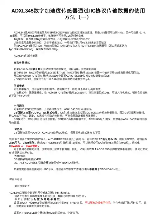
ADXL345数字加速度传感器通过IIC协议传输数据的使⽤⽅法(⼀)ADXL345是ADI公司推出的具有SPI和IIC数字输出功能的三轴加速度计,其最⼤的量程可达到 -16g,另外可选择 -2, -4,-8g量程,可采⽤4mg/LSB分辨率,该分辨率可测得0.25的倾⾓变化16g量程,意思就是16g时输出32768,-16g时输出-32768,2的16次⽅LSB的意思是最⼩有效位,为数字输出⽅式,⼀般我们可以⽤mg/LSB来表⽰灵敏度例如ADXL345量程为 /2g,输出的位数为10位(2的10次⽅共1024个LSB)对应满量程,那么灵敏度就为4g/1024LSB=3.9mv/g,取倒数为256LSB/g。
ADXL345引脚功能图⾃动休眠模式静⽌期间⾃动切换到休眠模式,可以省电。
要使能此功能,如果ADXL345在静⽌期在THRESH_INACT寄存器(地址0x25) 和TIME_INACT寄存器(地址0x26)设置⼀个值表⽰静⽌(适当值视应⽤⽽定),然后在POWER_CTL寄存器(地址0x2D) 中设置AUTO_SLEEP位(位D4)和链接位(位D5)。
VS为2.5V 时,该模式下低于12.5 Hz数据速率的功耗通常为23 µA。
待机模式更低功率操作,也可以使⽤待机模式。
待机模式下,功耗降低到0.1µA(典型值)。
该模式中,⽆测量发⽣。
在 POWER_CTL寄存器(地址0x2D)中,清除测量位(位D3),可进⼊待机模式。
器件在待机模式下保存FIFO内容串⾏通信可采⽤IIC和SPI数字通信。
上述两种情况下,ADXL345作为从机运⾏。
CS引脚上拉⾄VDD I/O,I2C模式使能模式使能。
CS引脚应始终上拉⾄VDD I/O或由外部控制器驱动,因为CS引脚⽆连接时,默认模式不存在。
因此,如果没有采取这些措施,可能会导致该器件⽆法通信。
SPI模式下,CS引脚由总线主机控制。
SPI和I2C两种操作模式下,ADXL345写⼊期间,应忽略从ADXL345传输到主器件的数据。
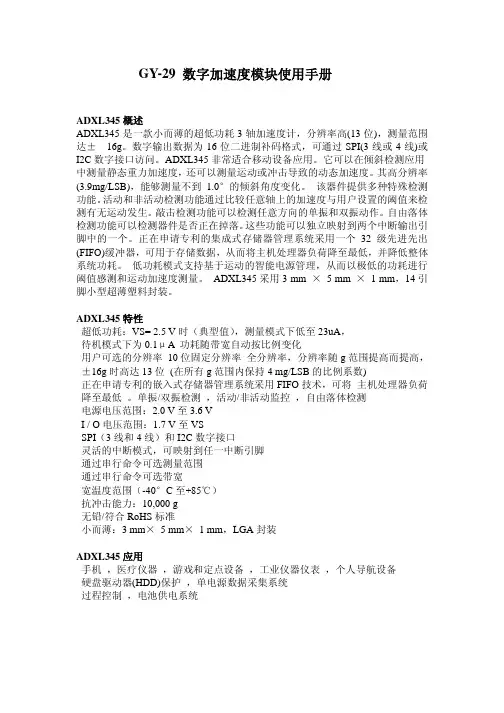
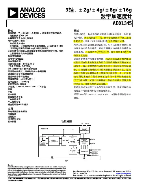
GY-29数字加速度模块使用手册ADXL345概述ADXL345是一款小而薄的超低功耗3轴加速度计,分辨率高(13位),测量范围达±16g。
数字输出数据为16位二进制补码格式,可通过SPI(3线或4线)或I2C数字接口访问。
ADXL345非常适合移动设备应用。
它可以在倾斜检测应用中测量静态重力加速度,还可以测量运动或冲击导致的动态加速度。
其高分辨率(3.9mg/LSB),能够测量不到1.0°的倾斜角度变化。
该器件提供多种特殊检测功能。
活动和非活动检测功能通过比较任意轴上的加速度与用户设置的阈值来检测有无运动发生。
敲击检测功能可以检测任意方向的单振和双振动作。
自由落体检测功能可以检测器件是否正在掉落。
这些功能可以独立映射到两个中断输出引脚中的一个。
正在申请专利的集成式存储器管理系统采用一个32级先进先出(FIFO)缓冲器,可用于存储数据,从而将主机处理器负荷降至最低,并降低整体系统功耗。
低功耗模式支持基于运动的智能电源管理,从而以极低的功耗进行阈值感测和运动加速度测量。
ADXL345采用3mm×5mm×1mm,14引脚小型超薄塑料封装。
ADXL345特性超低功耗:VS=2.5V时(典型值),测量模式下低至23uA,待机模式下为0.1μA功耗随带宽自动按比例变化用户可选的分辨率10位固定分辨率全分辨率,分辨率随g范围提高而提高,±16g时高达13位(在所有g范围内保持4mg/LSB的比例系数)正在申请专利的嵌入式存储器管理系统采用FIFO技术,可将主机处理器负荷降至最低。
单振/双振检测,活动/非活动监控,自由落体检测电源电压范围:2.0V至3.6VI/O电压范围:1.7V至VSSPI(3线和4线)和I2C数字接口灵活的中断模式,可映射到任一中断引脚通过串行命令可选测量范围通过串行命令可选带宽宽温度范围(-40°C至+85℃)抗冲击能力:10,000g无铅/符合RoHS标准小而薄:3mm×5mm×1mm,LGA封装ADXL345应用手机,医疗仪器,游戏和定点设备,工业仪器仪表,个人导航设备硬盘驱动器(HDD)保护,单电源数据采集系统过程控制,电池供电系统模块引脚图模块引脚说明序号名称描叙1VCC电源供给范围3-5v2NC空引脚3NC空引脚4INT2中断25INT1中断16GND电源地7GND电源地8CS片选9SDO SPI数据输出10SDA/SDIO SPI数据I/O,IIC数据线(兼容5v电平)11SCL SPI时钟线,IIC时钟线(兼容5v电平)12VCC电源供给范围3-5v模块参数名称参数工作电压3~5V工作电流5uA(ADDRES引脚不悬空时)通信方式IIC/SPI工作温度-40°~85°尺寸(长*宽*高)18.2mm×23.3mm×11.6mm 注:模块内部包含电平转换芯片,兼容5v接口通信模式。
ADXL345概述ADXL345是一款小而薄的超低功耗3轴加速度计,分辨率高(13位),测量范围达±16g。
数字输出数据为16位二进制补码格式,可通过SPI(3线或4线)或I2C数字接口访问。
ADXL345非常适合移动设备应用。
它可以在倾斜检测应用中测量静态重力加速度,还可以测量运动或冲击导致的动态加速度。
其高分辨率(3.9mg/LSB),能够测量不到1.0°的倾斜角度变化。
该器件提供多种特殊检测功能。
活动和非活动检测功能通过比较任意轴上的加速度与用户设置的阈值来检测有无运动发生。
敲击检测功能可以检测任意方向的单振和双振动作。
自由落体检测功能可以检测器件是否正在掉落。
这些功能可以独立映射到两个中断输出引脚中的一个。
正在申请专利的集成式存储器管理系统采用一个32级先进先出(FIFO)缓冲器,可用于存储数据,从而将主机处理器负荷降至最低,并降低整体系统功耗。
低功耗模式支持基于运动的智能电源管理,从而以极低的功耗进行阈值感测和运动加速度测量。
ADXL345采用3 mm × 5 mm × 1 mm,14引脚小型超薄塑料封装。
ADXL345特性超低功耗:VS= 2.5 V时(典型值),测量模式下低至23uA,待机模式下为0.1μA 功耗随带宽自动按比例变化用户可选的分辨率10位固定分辨率全分辨率,分辨率随g范围提高而提高,±16g时高达13位(在所有g范围内保持4 mg/LSB的比例系数)正在申请专利的嵌入式存储器管理系统采用FIFO技术,可将主机处理器负荷降至最低。
单振/双振检测,活动/非活动监控,自由落体检测电源电压范围:2.0 V至3.6 VI / O电压范围:1.7 V至VSSPI(3线和4线)和I2C数字接口灵活的中断模式,可映射到任一中断引脚通过串行命令可选测量范围通过串行命令可选带宽宽温度范围(-40°C至+85℃)抗冲击能力:10,000 g无铅/符合RoHS标准小而薄:3 mm× 5 mm× 1 mm,LGA封装。
摘要电子水平仪是一种非常普遍的测量小角度的量具。
用它可测量对于水平位置的倾斜度。
基于传感器、数字信号处理、单片机技术的数字水平仪是当前倾角测试仪器数字化发展的方向。
本毕业设计就是采用STC89C52单片机和ADI公司生产的三轴加速度传感器ADXL345相结合,利用ADXL345三轴加速度传感器感应水平倾角,通过单片机的控制以及运算将倾角以数值的形式直接在LCD显示屏上进行显示、处理,从而使角度测量变得方便、快捷,实现了倾角的高精度测量。
通过ADXL345三轴加速度传感器原理,提出了使用软件和硬件结合的自动校正技术进行测量角度,最大限度简化了电路,提高了系统的稳定性和可靠性。
通过对本课题的研究,让我对水平仪有了一定的了解,在未来水平仪将在建筑方面起着重要作用,并且随着时代发展,水平仪对角度的测量将越来越精细,随着光学应用领域的不断扩展,也相应的产生了一些基于光电原理的光电式水平仪和激光式水平仪,光电原理的应用将是未来水平仪的发展方向。
关键词:智能水平仪;单片机;ADXL345;角度AbstractElectronic level gauge is a very common small angle measurement. Measurement for the horizontal position of the inclination to use it. Based on the digital level sensor, digital signal processing, computer technology is the current development of digital instrument tilt testing instrument in the direction of.This graduation design is the use of three axis accelerometer ADXL345 microcontroller STC89C52 and ADI company production of combination, using the ADXL345 three axis acceleration sensor level angle, processing through the MCU control and operation will dip in numerical form directly in the LCD screen display,, so that the angle measuring is convenient, quick, realize high precision measurement of angle. The principle of the ADXL345 three axis accelerometer, and proposes to use the combination of hardware and software of the automatic calibration technique for measuring the angle, the maximum simplifies the circuit, improves the stability and reliability of the system.This graduation design is the use of three axis accelerometer ADXL345 microcontroller STC89C52 and ADI company production of combination, using the ADXL345 three axis acceleration sensor level angle, processing through the MCU control and operation will dip in numerical form directly in the LCD screen display,, so that the angle measuring is convenient, quick, realize high precision measurement of angle. The principle of the ADXL345 three axis accelerometer, and proposes to use the combination of hardware and software of the automatic calibration technique for measuring the angle, the maximum simplifies the circuit, improves the stability and reliability of the system.Keywords: Intelligent level; MCU; ADXL345; angle目录1 绪论 (1)1.1 课题研究背景和意义 (1)1.2 国内外水平仪发展现状和趋势 (1)1.3 系统设计的主要工作 (1)1.4 论文结构及安排 (2)2 三轴加速度传感器感应原理 (3)2.1 ADXL345工作原理 (3)2.2 ADXL345寄存器映射 (5)2.3 ADXL345主要寄存器定义介绍 (6)2.4 测量倾斜角度原理 (8)2.4.1 加速度传感器进行倾角测量简介 (8)2.4.2 ADXL345测量角度原理 (9)3 水平仪总体设计 (12)3.1 水平仪硬件设计 (12)3.1.1 单片机模块 (13)3.1.2 LCD液晶显示模块 (14)3.1.3 ADXL345接口设计 (16)3.1.4 ADXL345加速度传感器模块 (18)3.2 水平仪软件设计 (20)3.2.1 I2C总线协议分析 (21)3.2.2 液晶显示驱动程序设计 (25)3.2.3 ADXL345加速度传感器软件模块 (28)3.2.4 ADXL345加速度传感器误差校准 (28)4 实验数据及总结 (30)结论 (33)致谢 (34)附录A 英文原文 (37)附录B 汉语翻译 (41)附录C 主程序 (44)附录D 电路原理图 (55)1 绪论1.1 课题研究背景和意义在高楼桥梁等建筑行业,对建筑物自身在水平面倾斜度的测量和处理,需要一个能连续工作几个月甚至一年以上采样进度很高的数字水平仪系统,这就要求该系统必须具有高精度微功耗的功能。
程序说明:该程序中有两个C文件,均为同一Keil或TKstudio 工程下的C源文件,分别为ADXL345_main和ADXL345_LCD,此程序在Keil uVision2或TKstudio version4.5编译环境下均可正常运行,"ADXL345" - 0 Error(s), 0 Warning(s).项目说明:采用全集成的三轴加速度传感器ADXL345进行二维倾角的测量,用1602液晶(LCD省去了测忙函数)显示角度值,其值精确到小数点后两位。
ADXL345_main.c文件:/**********************头文件*************************/#include <reg51.h>#include <math.h>#include <intrins.h>/***********************宏定义***********************/#define uchar unsigned char#define uint unsigned int/**********************位定义************************/sbit CS = P2^1; // 片选信号端sbit SCLK = P3^1; // 时钟sbit SDI = P3^0; // 数据读/写/***********************函数声明**********************///void write_comd(uchar);//void write_data_LCD(uchar);void LCD_init(); // LCD 初始化void display_LCD(); // LCD显示void calculate(); // ASCII码计算/***********************全局变量**********************/uint Data_X_2[2]; // 读出的数据储存X Y Zuint Data_Y_2[2];uint Data_Z_2[2];int Data_X,Data_Y,Data_Z; // 数值转换后的值float XX,YY,ZZ; // 3轴的重力加速度分量uchar ID; // 机器ID值用于看读的是否对(调试时用)float roll,pitch;/********************************************************************* ** 函数名:Delayms()** 功能描述:产生延迟** 形参:ms 延迟的时间,单位ms * * 返回值:无** 局部变量:i ** 全局变量:无** 函数调用:无** *********************************************************************/ void delay_ms(uchar ms){uchar i;while(ms--){for(i = 0; i< 250; i++){_nop_();_nop_(); //空执行消耗CPU时间达到等待的效果_nop_();_nop_();}}}/********************************************************************* ** 函数名:Write_Data(uchar Data_write) ** 功能描述:写指令到寄存器** 形参:Data_write 要写的数据8位** 返回值:无** 局部变量:i ** 全局变量:无** 函数调用:_nop_(); ** *********************************************************************//*************************写数据函数*******************/void Write_Data(uchar Adress_Reg,uchar Data_write){uchar i=0;Adress_Reg=(Adress_Reg & 0x7f); // 置最高位位0 写状态Adress_Reg=(Adress_Reg & 0xbf); // 置第二高位0 单字节读写CS=0;_nop_();SCLK=1;_nop_();for(i=0;i<8;i++) // 8位串行输出寄存器地址值{SCLK=0;_nop_();SDI=(bit)(Adress_Reg & 0x80);_nop_();_nop_();_nop_();SCLK=1;_nop_();_nop_();Adress_Reg<<=1;}for(i=0;i<8;i++) // 8位串行输出指令值{SCLK=0;_nop_();SDI=(bit)(Data_write & 0x80);_nop_();_nop_();_nop_();SCLK=1;_nop_();_nop_();Data_write<<=1;}_nop_();_nop_();SCLK=1;_nop_();_nop_();SDI=1;CS=1;}/******************************************************************** * * * 函数名:Read_Data_Reg(uchar Adress_Reg) ** 功能描述:往寄存器读数据* * 形参:Adress_Reg 寄存器地址** 返回值:Data_Read 读取的数据** 局部变量:i Data_Read 读取的数据* * 全局变量:无* * 函数调用:_nop_(); * * * ********************************************************************/ uchar Read_Data_Reg(uchar Adress_Reg){uchar i=0;uchar Data_Read;Adress_Reg=(Adress_Reg|0x80); // 置最高位为1,读状态Adress_Reg=(Adress_Reg&0xbf); // 置第二高位位0,单字节读写CS=0;_nop_();_nop_();SCLK=1;_nop_();_nop_();for(i=0;i<8;i++) // 8位串行输出寄存器地址值{SCLK=0;_nop_();SDI=(bit)(Adress_Reg & 0x80);_nop_();_nop_();_nop_();SCLK=1;_nop_();_nop_();Adress_Reg<<=1;}for(i=0;i<8;i++) // 8位串行读入数据(8位){SCLK=0;Data_Read<<=1;_nop_();Data_Read|=(uchar)SDI;_nop_();_nop_();SCLK=1;_nop_();_nop_();}for(i=0;i<8;i++) // 产生8个脉冲(手册要求,目的不知道){SCLK=0;_nop_();_nop_();SCLK=1;_nop_();_nop_();}_nop_();_nop_();SCLK=1;_nop_();CS=1;return Data_Read;}/********************************************************************* ** 函数名:Read_Data() ** 功能描述:读出6字节X Y Z 轴各两字节的数据** 形参:无** 返回值:无** 局部变量:无** 全局变量:Data_X_2[2] Data_Y_2[2] Data_Z_2[2] 存放读出值** 函数调用:Read_Data_Reg(__);delay_ms(__); ** *********************************************************************/void Read_Data(){/*DATAX0是X轴加速度的低字节寄存器,DA TAX1是高字节寄存器*/Data_X_2[0]=Read_Data_Reg(0x32); // 读出X轴低位Data_X_2[1]=Read_Data_Reg(0x33); // 读出X轴高位delay_ms(10);Data_Y_2[0]=Read_Data_Reg(0x34); // 读出Y轴低位Data_Y_2[1]=Read_Data_Reg(0x35); // 读出Y轴高位delay_ms(10);Data_Z_2[0]=Read_Data_Reg(0x36); // 读出Z轴低位Data_Z_2[1]=Read_Data_Reg(0x37); // 读出Z轴高位}/********************************************************************* ** 函数名:ADXL345_init() ** 功能描述:ADXL345 初始化对寄存器写指令** 形参:无** 返回值:无** 局部变量:无** 全局变量:无** 函数调用:Write_Data_Reg(__,__); ** *********************************************************************/void ADXL345_init(){Write_Data(0x31,0x4f); //测量范围为正负16g 13位模式3线SPI 中断低有效禁用自测力左对齐(MSB)模式delay_ms(10);Write_Data(0x2C,0x08); //速率设定为25HZ,带宽12.5HZdelay_ms(10);Write_Data(0x2D,0x08); //选择电源模式delay_ms(10);Write_Data(0x2E,0x80); //使能DA TA_READY 中断delay_ms(10);Write_Data(0x2f,0x00); //中断功能设定,不使用中断delay_ms(10);/*Write_Data(0x1E,0x00); //X 偏移量根据测试传感器的delay_ms(10);Write_Data(0x1F,0x00); //Y 偏移量根据测试传感器的delay_ms(10);Write_Data(0x20,0x00); //Z 偏移量根据测试传感器的delay_ms(10);Write_Data(0x21,0x00); //敲击延时0:禁用; (1.25ms/LSB)delay_ms(10);Write_Data(0x22,0x00); //检测第一次敲击后的延时0:禁用; (1.25ms/LSB)delay_ms(10);Write_Data(0x23,0x00); //敲击窗口0:禁用; (1.25ms/LSB)delay_ms(10);Write_Data(0x24,0x00); //保存检测活动阀值; (62.5mg/LSB)delay_ms(10);Write_Data(0x25,0x00); //保存检测静止阀值; (62.5mg/LSB)delay_ms(10);Write_Data(0x26,0x2b); //检测活动时间阀值; (1s/LSB)delay_ms(10);Write_Data(0x27,0x00); // 活动静止检测禁止delay_ms(10);Write_Data(0x28,0x09); //保存检测活动阀值; (62.5mg/LSB)delay_ms(10);Write_Data(0x29,0xff); //保存检测静止阀值; (62.5mg/LSB)delay_ms(10);Write_Data(0x2a,0x80);delay_ms(10);*/}/******************************************************************** * * * 函数名:transform(void) ** 功能描述:数值整合和转换,并转换为加速度放大1000倍* * 形参:无* * 返回值:无* * 局部变量:无* * 全局变量:Data_X=0,Data_Y=0,Data_Z 整合后的X Y Z 轴值* * 函数调用:无* * * ********************************************************************//*从数据寄存器中获取加速度数据后,用户必须对数据进行重建*//***************************数值转换***********************/void transform(void){(int)Data_X=(Data_X_2[0])+(Data_X_2[1]<<8);(int)Data_Y=(Data_Y_2[0])+(Data_Y_2[1]<<8);(int)Data_Z=(Data_Z_2[0])+(Data_Z_2[1]<<8);if(Data_X&0x2000){ // 若位负数转换为补码Data_X=(~Data_X)+1;Data_X=Data_X*3.90625; // 乘比例因素Data_X=-Data_X;}else{Data_X=Data_X*3.90625;}if(Data_Y&0x2000){ // 若位负数转换为补码Data_Y=(~Data_Y)+1;Data_Y=Data_Y*3.90625; // 乘比例因素Data_Y=-Data_Y;}else{Data_Y=Data_Y*3.90625;}if(Data_Z&0x2000){ // 若位负数转换为补码Data_Z=(~Data_Z)+1;Data_Z=Data_Z*3.90625; // 乘比例因素Data_Z=-Data_Z;}else{Data_Z=Data_Z*3.90625;}/*if(Data_X<0){Data_X=-Data_X;Data_X=(float)Data_X*3.9;//Data_X单位为1000倍的g,即mg }else{Data_X=(float)Data_X*3.9;}if(Data_Y<0){Data_Y=-Data_Y;Data_Y=(float)Data_Y*3.9;}else{Data_Y=(float)Data_Y*3.9;}if(Data_Z<0){Data_Z=-Data_Z;Data_Z=(float)Data_Z*3.9;}else{Data_Z=(float)Data_Z*3.9;}*//*扩大1000倍后结果*//*检测轴始终检测到的是正加速度*/XX=Data_X; // X轴重力加速度分量YY=Data_Y; // Y轴重力加速度分量ZZ=Data_Z; // Z轴重力加速度分量}/******************************************************************** * * * 函数名:calculate_angle(float V_x,float V_y,float V_z) ** 功能描述:计算横滚角和俯仰角* * 形参:G_x G_x G_z X Y Z轴的加速度值* * 返回值:无* * 局部变量:无* * 全局变量:roll pitch 横滚角和俯仰角** 函数调用:atan2(_,_); ** * ********************************************************************//*********计算角度函数***************/void calculate_angle(float G_x,float G_y,float G_z){roll=-(float)(((atan2(G_z,G_x)*180)/3.1415926535)-90);//弧度转成角度pitch=-(float)(((atan2(G_z,G_y)*180)/3.1415926535)-90);roll=roll*100;pitch=pitch*100;}/*************************主函数***************************/void main(void){delay_ms(5); //上电延时ADXL345_init(); // ADXL345的初始化LCD_init(); // LCD的初始化ID=Read_Data_Reg(0x00); // 读出机器ID值,DEVID寄存器保存0xE5的固定器件ID 代码while(1){Read_Data(); //读出X Y Z 轴加速度值transform(); //数据重建过程calculate_angle(XX,YY,ZZ); //计算x和y轴相对于水平面的倾角calculate(); // ASCII码计算display_LCD(); // 显示}}ADXL345_LCD.c文件:#include <reg51.h> //51寄存器文件#include <intrins.h>/***********************宏定义***********************/#define uchar unsigned char#define uint unsigned int/**********************位定义及变量声明************************/sbit LCDEN=P3^4;sbit RS=P3^5;sbit DULA=P2^6;sbit WEILA=P2^7;extern uchar ID;extern float roll,pitch;uchar dis1[16] = {"X+00.00 Y+00.00"};uchar dis2[16] = {"ID:000"};/*******************计算函数********************/void calculate(){//uchar flag_X,flag_Y;if(roll<0){roll=-roll;dis1[1]='-';//flag_X=45;}else{dis1[1]='+';}if(pitch<0){pitch=-pitch;dis1[10]='-';//flag_Y=45;}else{dis1[10]='+';}dis1[0]='X';//dis1[1]=flag_X;dis1[2]=(int)roll%10000/1000+48;dis1[3]=(int)roll%10000%1000/100+48;dis1[4]='.';dis1[5]=(int)roll%10000%1000%100/10+48;dis1[6]=(int)roll%10000%1000%100%10+48;dis1[9]='Y';//dis1[10]=flag_Y;dis1[11]=(int)pitch%10000/1000+48;dis1[12]=(int)pitch%1000/100+48;dis1[13]='.';dis1[14]=(int)pitch%1000%100/10+48;dis1[15]=(int)pitch%1000%100%10+48;dis2[0]='I';dis2[1]='D';dis2[2]=':';dis2[3]=ID/100+48;dis2[4]=ID%100/10+48;dis2[5]=ID%100%10+48;}/*******************延时函数********************/ void delay(uint k){uint j,i;for(j=k;j>0;j--)for(i=100;i>0;i--);}/*******************液晶显示相关函数********************/void write_comd(uchar com){RS=0;//数据/命令选择端P0=com;delay(1);//数据建立时间LCDEN=1;delay(5);LCDEN=0;}void write_data_LCD(uchar datas){RS=1;//数据/命令选择端P0=datas;delay(1);//数据建立时间LCDEN=1;delay(5);LCDEN=0;}void LCD_init(){DULA=0;WEILA=0;LCDEN=0;write_comd(0x38);//显示模式设置write_comd(0x0c);//开显示,不显示光标write_comd(0x06);//写一个字符后,地址指针加1且光标加1;整屏显示不移动write_comd(0x01);//显示清屏}void display_LCD(){uint i,j;write_comd(0x80);//初始化数据指针,写在第一行for(i=0;i<16;i++){write_data_LCD(dis1[i]);delay(1);}write_comd(0x80+0x40);//将数据指针移动到第二行第4字符处开始显示for(j=0;j<6;j++){write_data_LCD(dis2[j]);delay(1);}}。
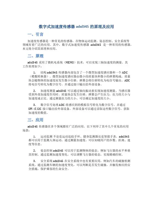
数字式加速度传感器adxl345的原理及应用一、引言加速度传感器是一种常见的传感器,在物体运动监测、姿态控制、安全系统等领域有着广泛的应用。
其中,数字式加速度传感器adxl345是一种常用的传感器,本文将介绍其原理和应用。
二、原理adxl345采用了微机电系统(MEMS)技术,可以实现三轴加速度的测量。
其工作原理如下:1.结构 adxl345传感器内部包含了一个微型加速度感应器和一个ADC(模数转换器)。
微型加速度感应器由微小的质量块和微小的弹簧构成,质量块会随物体的加速度而发生微小位移,弹簧会将位移转化为电信号输出。
ADC 将电信号转化为数字信号,并通过接口输出给外部设备。
2.加速度测量 adxl345可以通过轴向振动来实现加速度测量。
当感应器受到外部加速度作用时,质量块会发生位移,弹簧会产生拉力,拉力的大小与加速度成正比。
通过测量拉力的大小,可以确定加速度的大小。
3.数字信号处理 ADC将感应到的模拟信号转化为数字信号,并通过SPI或I2C接口输出给外部设备。
外部设备可以通过读取这些数字信号,获取加速度的数值。
三、应用adxl345传感器在多个领域都有广泛的应用,以下列举了其中几个常见的应用场景:1.运动监测不论是运动追踪手环、健身监测器还是智能手表,adxl345都可以用于监测人体运动。
通过测量加速度,可以知晓用户的步数、距离、速度等信息。
2.姿态控制 adxl345可以用于监测物体的姿态,例如飞行器的水平和垂直控制。
通过监测加速度变化,可以调整飞行器的姿态,实现精确控制。
3.安全系统 adxl345在安全系统中也有重要应用,例如汽车的碰撞检测系统。
通过监测车辆的加速度变化,可以判断是否发生碰撞,并触发相应的安全措施,保护乘客的生命安全。
四、优缺点adxl345作为一种数字式加速度传感器,具有以下优点:•高精度:adxl345采用了MEMS技术,具有很高的测量精度。
•数字信号输出:传感器输出数字信号,方便与其他设备进行通信和处理。
ADXL345快速运用指南作者 zagGard 2011年1月10日描述:ADXL345是一款体型小而轻薄的超低功耗3轴加速度计,分辨率高13位,测量范围± 16g。
数字输出数据为16位二进制补码格式,可通过SPI(3线或4线)或I2C 数字接口访问。
ADXL345非常适合应用于移动设备。
它可以在倾斜检测应用中测量静态重力加速度,还可以测量运动或冲击导致的动态加速度。
其高分辨率为4mg/LSB,能够测量不到1.0°的倾斜角度变化。
该器件提供多种特殊检测功能。
活动和非活动检测功能通过比较任意轴上的加速度与用户设置的阈值来检测有无运动发生。
敲击检测功能可以检测任意方向的单振和双振动作。
自由落体检测功能可以检测器件是否正在掉落。
这些功能可以独立映射到两个中断输出引脚中的一个。
正在申请专利的集成式存储器管理系统采用一个32级先进先出(FIFO)缓冲器,可用于存储数据,从而将主机处理器负荷降至最低,并降低整体系统功耗。
低功耗模式支持基于运动的智能电源管理,从而以极低的功耗进行阈值感测和运动加速度测量。
特征:2.0-3.6V直流供电超低功耗:测量模式时40uA,待机时0.1uA@2.5V单振/双振检测自由落体检测SPI和I2C数字接口数据传输:这部分的指南说明了如何把Arduino ADXL345连接到面包板。
下面是一个描述Arduino引脚应该连接到的加速度计引脚的表:初学者的示例代码:让我们看一个获得ADXL345和Arduino运行的示例。
你可以在这里下载完整的代码。
下面我们将检查该代码的不同部分。
这是代码的初始化部分,这真的非常基本,这里是正在发生的。
SPI.h库被添加到程序。
SPI是Arduino使用于传达给ADLX345的通信协议,一个名为CS的变量存储片选信号的针数,是为ADXL345寄存器创建的变量,这些变量存储的指示的寄存器的地址和用于从加速计设置和检索的值。
数据表显示所有可用的ADXL345及其地址寄存器。
摘要:本系统采用美国TI公司超低功耗单片机MSP430,制作出一台可以测量出倾斜角度,x、y、z三个方向的重力加速度分量的手持倾角测量仪。
系统集成了MSP430、三轴加速度传感器ADXL345、低功耗笔段式液晶显示屏、高效率DC-DC降压模块TPS54331、1.5-25v升压模块等硬件电路。
降压模块效率高达90%,单个2200uf/50v电解电容充电到25v可以让MSP430单片机工作一分多钟,真正实现了超低功耗。
系统角度测量精度达±1度,重力加速度分量精度达±5%,显示分辨率0.1度,符合设计要求。
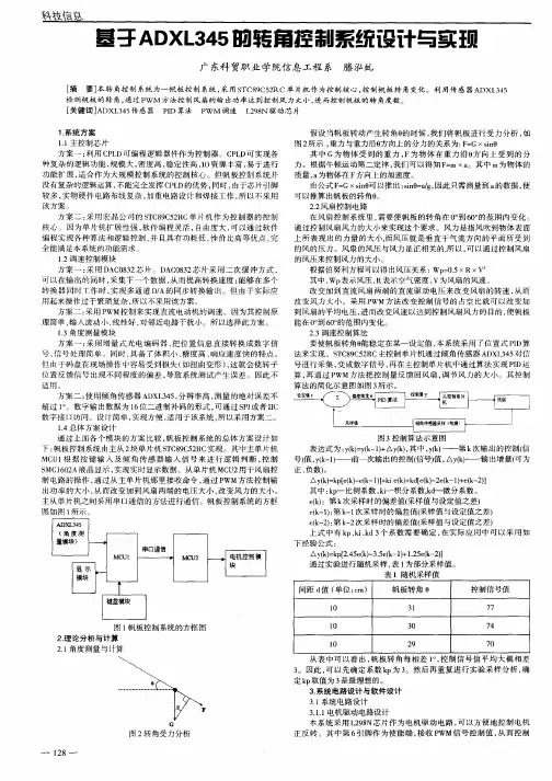
关键词:超低功耗,MSP430,倾角测量,ADXL345模块1 系统方案本倾角测量仪耗电极低,要求用单个充电到25v的2200uf电解电容可以工作至少60秒,5秒测量一次。
倾角测量仪的测角范围为0~90度,测量精度要求达到±5度。
并且可以测量并显示沿X、Y、Z方向重力加速度分量的功能,要求测量精度为±5%。
可以总结地说,本系统原理简单,但是要求苛刻,需要参赛队员认真选取器件,做到不在任何一个地方浪费电能,同时不为节省电能而丢失半点精度。
1.1设计思路以MSP430单片机位系统控制核心,利用ADXL345三轴加速度传感器把重力加速度分量转化为单片机可以处理的数字量,最终得到我们需要的倾角量。
2200uf\50v 电解电容充电至25v后经DC-DC降压稳压至2.7v后给整个系统供电。
系统结构见图1:图1 系统结构图1.2方案论证1.2.1MCU的选择本系统的一大要求就是低功耗,而MCU是本系统耗电最多的单元之一,如何才能使充电25v的2200uf电容给系统供电一分多钟,毫无疑问MCU的选择至关成败.方案一:mega16单片机功能强大,性能优越,速度快。
但是功耗大,完全不能胜任。
方案二:MSP430单片机是TI推出一种16位超低功耗、具有精简指令集(RISC)的混合信号处理器(Mixed Signal Processor),并且具有强大地休眠和唤醒功能。
医用直线加速器三维电子倾角仪的设计与研制袁夏冰;钱三杨;金燕;姚金红【摘要】目的:自主研发专门用于医用直线加速器水平调节测量的三维电子倾角仪,以提高医用直线加速器质量控制过程中的测量精度和稳定性,保证放射性治疗过程的安全性和可靠性.方法:三维电子倾角仪采用STM32F103T8U6为主控芯片,ADXL345为三维角度传感器,角度传感器测得的倾角数据通过SPI总线通讯方式传送给主控芯片,再通过无线蓝牙方式传输到显示模块上.结果:测得的数据结果精度和分辨率较高,相对误差范围<±0.5%,可以测0°~90°的任意角度,且能够检测到<0.25°的倾斜角度变化.结论:三维电子倾角仪专为直线加速器水平调节测量而设计,且实用性强,可替代传统式气泡水平仪.【期刊名称】《中国医学装备》【年(卷),期】2019(016)004【总页数】5页(P12-16)【关键词】水箱;单片机;角度传感器;医用直线加速器;倾角仪【作者】袁夏冰;钱三杨;金燕;姚金红【作者单位】南京医科大学附属苏州医院医学工程处江苏苏州 215000;南京医科大学附属苏州医院医学工程处江苏苏州 215000;南京医科大学附属苏州医院医学工程处江苏苏州 215000;南京医科大学附属苏州医院医学工程处江苏苏州215000【正文语种】中文【中图分类】R197.39放射治疗是目前肿瘤治疗重要方法之一,精确度是放射治疗疗效的一个关键因素,因此放射治疗对治疗设备的精确度要求非常高,需要定期对设备进行质量控制检测,其中加速器床板、机架、准直器角度的测量与验证,以及质量控制设备二维水箱、三维水箱和固体水模体测量之前的水平调节等都需要用到角度测量仪[1]。
水箱是应用于直线加速器各项参数调试和验收的重要工具,在测量过程中水箱需保持足够水平,从而保证测量参数的准确性[2]。
目前,质量控制中配备的大都是水泡型水平仪或直条状或框式的一维或二维水平仪[3-4]。
ADXL345经验总结,采⽤SPI和I2C总线操作⼀、 ADXL345简介ADXL345是ADI公司推出的三轴(x,y,z)iMEMS数字加速度计(digital accelerometer ),具有在16G下⾼分辨率(13Bit)测量能⼒,同时具备16Bit数字输出。
ADXL345 适⽤于静态倾⾓测量以及动态加速度测量,⾼达4mg/LSB的灵敏度允许测量⼩于1度的倾⾓。
该传感器还具备单击 /双击探测,⾃由落体探测,并允许⽤户设置⼀个加速度阀值,当加速度值超过设定阀值后可以产⽣⼀个信号输出。
所有这些功能都可以映射到2个中断上。
内置的32级FIFO缓存可以极⼤的缓解处理器的压⼒。
特点:2.0 -3.6VDC供电电压超低功耗: 40uA的测量模式, 0.1uA在standby@2.5V单击/双击检测⾃由落体检测⽤户阀值设定SPI和I2C接⼝ADXL345以+2.5V的电源电压⼯作时的消耗电流控制为标准25µ~130µA。
该产品可⽐与3轴惯性传感器节约80%的耗电量。
主要⾯向⼿机、便携式游戏机、游戏机控制器以及PND等。
还⽀持硬盘的跌落检测等。
可检测的加速度范围为±2/4/8/16G。
集成了FIFO(First-in, First-out)型存储器,最多可存储32组3轴数据。
耐冲击性为1万G。
输出接⼝备有I2C和SPI。
数据输出速度为0.1~3.2kHz。
电源电压(Vs)为+2.0~3.6V,接⼝部分为+1.8V~Vs。
⼯作温度范围为-40~+85℃。
封装采⽤14端⼦的LFCSP。
⼆、 SPI-4线模式操作ADXL345内部寄存器编程要点1.ADXL345 SPI-4线模式的硬件连接电路SPI-4线模式是adxl345默认的操作总线,⽆需配置即可⽤。
,详见datasheet page25 DAT A_FORMAT寄存器。
2.关于ADXL345的PI总线协议与标准的SPI协议的⼀些差异(标准的SPI协议可以参考这⾥不做详细介绍)标准的SPI总线时序中,每个字节之间的操作是断开的,即⽚选线SS_n和串⾏时钟线SCLK 正在传输该字节时有效,其余时刻保持⽆效状态(即SS_n=1,SCLK=1)如下图:ADXL345 datasheet中要求clock polarity (CPOL) = 1 and clock phase (CPHA) = 1,这可以在SOPC中选择SPI IP核作为nios2外设构建系统时,⽤GUI的⽅式⽅便的设置,其SPI操作的时序如下图:从图中可以看到:SPI总线对ADXL345内部寄存器的读写操作都是以字节为单位进⾏的(这是由ADXL345内部30个可操作寄存器均为字节寄存器所决定的),然⽽每两个字节数据/地址之间CS_n和SCLK⼀直需要保持有效。
摘要电子水平仪是一种非常普遍的测量小角度的量具。
用它可测量对于水平位置的倾斜度。
基于传感器、数字信号处理、单片机技术的数字水平仪是当前倾角测试仪器数字化发展的方向。
本毕业设计就是采用STC89C52单片机和ADI公司生产的三轴加速度传感器ADXL345相结合,利用ADXL345三轴加速度传感器感应水平倾角,通过单片机的控制以及运算将倾角以数值的形式直接在LCD显示屏上进行显示、处理,从而使角度测量变得方便、快捷,实现了倾角的高精度测量。
通过ADXL345三轴加速度传感器原理,提出了使用软件和硬件结合的自动校正技术进行测量角度,最大限度简化了电路,提高了系统的稳定性和可靠性。
通过对本课题的研究,让我对水平仪有了一定的了解,在未来水平仪将在建筑方面起着重要作用,并且随着时代发展,水平仪对角度的测量将越来越精细,随着光学应用领域的不断扩展,也相应的产生了一些基于光电原理的光电式水平仪和激光式水平仪,光电原理的应用将是未来水平仪的发展方向。
关键词:智能水平仪;单片机;ADXL345;角度AbstractElectronic level gauge is a very common small angle measurement. Measurement for the horizontal position of the inclination to use it. Based on the digital level sensor, digital signal processing, computer technology is the current development of digital instrument tilt testing instrument in the direction of.This graduation design is the use of three axis accelerometer ADXL345 microcontroller STC89C52 and ADI company production of combination, using the ADXL345 three axis acceleration sensor level angle, processing through the MCU control and operation will dip in numerical form directly in the LCD screen display,, so that the angle measuring is convenient, quick, realize high precision measurement of angle. The principle of the ADXL345 three axis accelerometer, and proposes to use the combination of hardware and software of the automatic calibration technique for measuring the angle, the maximum simplifies the circuit, improves the stability and reliability of the system.This graduation design is the use of three axis accelerometer ADXL345 microcontroller STC89C52 and ADI company production of combination, using the ADXL345 three axis acceleration sensor level angle, processing through the MCU control and operation will dip in numerical form directly in the LCD screen display,, so that the angle measuring is convenient, quick, realize high precision measurement of angle. The principle of the ADXL345 three axis accelerometer, and proposes to use the combination of hardware and software of the automatic calibration technique for measuring the angle, the maximum simplifies the circuit, improves the stability and reliability of the system.Keywords: Intelligent level; MCU; ADXL345; angle目录1 绪论 (1)1.1 课题研究背景和意义 (1)1.2 国内外水平仪发展现状和趋势 (1)1.3 系统设计的主要工作 (1)1.4 论文结构及安排 (2)2 三轴加速度传感器感应原理 (3)2.1 ADXL345工作原理 (3)2.2 ADXL345寄存器映射 (5)2.3 ADXL345主要寄存器定义介绍 (6)2.4 测量倾斜角度原理 (8)2.4.1 加速度传感器进行倾角测量简介 (8)2.4.2 ADXL345测量角度原理 (9)3 水平仪总体设计 (12)3.1 水平仪硬件设计 (12)3.1.1 单片机模块 (13)3.1.2 LCD液晶显示模块 (14)3.1.3 ADXL345接口设计 (16)3.1.4 ADXL345加速度传感器模块 (18)3.2 水平仪软件设计 (20)3.2.1 I2C总线协议分析 (21)3.2.2 液晶显示驱动程序设计 (25)3.2.3 ADXL345加速度传感器软件模块 (28)3.2.4 ADXL345加速度传感器误差校准 (28)4 实验数据及总结 (30)结论 (33)致谢 (34)附录A 英文原文 (37)附录B 汉语翻译 (41)附录C 主程序 (44)附录D 电路原理图 (55)1 绪论1.1 课题研究背景和意义在高楼桥梁等建筑行业,对建筑物自身在水平面倾斜度的测量和处理,需要一个能连续工作几个月甚至一年以上采样进度很高的数字水平仪系统,这就要求该系统必须具有高精度微功耗的功能。
ARDUINO SENSOR ACCELEROMETERUser ManualDescription:The ADXL345 is a small, thin, low power, 3-axis accelerometer with high resolution (13-bit) measurement at up to ±16 g. Digital output data is formatted as 16-bit twos complement and is accessible through either a SPI (3- or 4-wire) or I2C digital interface. The ADXL345 is well suited to measure the static acceleration of gravity in tilt-sensing applications, as well as dynamic acceleration resulting from motion or shock. Its high resolution (4 mg/LSB) enables measurement of inclination changes less than 1.0°. Several special sensing functions are provided. Activity and inactivity sensing detect the presence or lack of motion and if the acceleration on any axis exceeds a user-set level. Tap sensing detects single and double taps. Free-fall sensing detects if the device is falling. These functions can be mapped to one of two interrupt output pins. An integrated, patent pending 32-level first in, first out (FIFO) buffer can be used to store data to minimize host processor intervention. Low power modes enable intelligent motion-based power management with threshold sensing and active acceleration measurement at extremely low power dissipation.Features:∙ 2.0-3.6VDC Supply Voltage∙UltraLowPower:40uAinmeasurementmode,*******************∙ Tap/Double Tap Detection∙ Free-Fall Detection∙ SPI and I2C interfacesHere is a diagram in case you like pictures!Beginner Sample Code:Let's look at a sketch to get the ADXL345 up and running with an Arduino. You can download the sketch in its entirety here. Below we'll examine what the different sections of this code does.//These variables will be used to hold the x,y and z axis accelerometer values.int x,y,z;This is the initialization section of the sketch. It's pretty basic really. Here's what's happening.1.The SPI.h library is added to the sketch. SPI is a communication protocol used by Arduino tocommunicate to the ADLX345.2. A variable named CS is created to store the pin number of the Chip Select signal.3.Variables are created for several of the ADXL345 registers. These variables store the address ofthe indicated registers and are used to set and retrieve values from the accelerometer.The datasheet shows all of the registers available on the ADXL345 and their addresses.4.Variables are created that will hold information that has been retrieved from theaccelerometer.//The ADXL345 gives 10-bit acceleration values, but they are stored as bytes (8-bits). To get the full value, two bytes must be combined for each axis.//The X value is stored in values[0] and values[1].x = ((int)values[1]<<8)|(int)values[0];//The Y value is stored in values[2] and values[3].y = ((int)values[3]<<8)|(int)values[2];//The Z value is stored in values[4] and values[5].z = ((int)values[5]<<8)|(int)values[4];//Print the results to the terminal.Serial.print(x, DEC);Serial.print(',');Serial.print(y, DEC);Serial.print(',');Serial.println(z, DEC);delay(10);}The main section of the sketch is split into two parts: the setup and the loop. The setup section is used to configure different aspects of the Arduino to communicate with the ADXL345. At the end of the setup section two functions are used to put the accelerometer into the mode we want to use (+/-4g detection, and enable measurement mode). The functions will be discussed in the next section of the sketch.The loop does most of the work in the sketch. Here's what's going on in the loop:1.Arduino reads 6 register values from the ADXL345 using the readRegister function. Thiscommand reads the x, y and z acceleration values from the accelerometer and stores them in the buffer named "values" that was created in the initialization section of the sketch.2.When values are read from the accelerometer they are returned in bytes. A byte is only 8 bits,but the accelerometer reports acceleration with up to 10 bits! In order to see the correctacceleration value we have to concatenate two bytes together. The x, y and z accelerationvalues are determined by concatenating the bytes from the values buffer.3.The acceleration values are printed to the serial terminal4.The sketch waits for 10ms before executing the loop again. This will allow the loop to run atroughly 100 hz.// char registerAddress - The register to write a value to// char value - The value to be written to the specified register.void writeRegister(char registerAddress, char value){//Set Chip Select pin low to signal the beginning of an SPI packet.digitalWrite(CS, LOW);//Transfer the register address over SPI.SPI.transfer(registerAddress);//Transfer the desired register value over SPI.SPI.transfer(value);//Set the Chip Select pin high to signal the end of an SPI packet.digitalWrite(CS, HIGH);}//This function will read a certain number of registers starting from a specified address and store thei r values in a buffer.//Parameters:// char registerAddress - The register addresse to start the read sequence from.// int numBytes - The number of registers that should be read.// char * values - A pointer to a buffer where the results of the operation should be stored.void readRegister(char registerAddress, int numBytes, char * values){//Since we're performing a read operation, the most significant bit of the register address should be set.char address = 0x80 | registerAddress;//If we're doing a multi-byte read, bit 6 needs to be set as well.if(numBytes > 1)address = address | 0x40;//Set the Chip select pin low to start an SPI packet.digitalWrite(CS, LOW);//Transfer the starting register address that needs to be read.SPI.transfer(address);//Continue to read registers until we've read the number specified, storing the results to the input bu ffer.for(int SPI.transfer(0x00);}//Set the Chips Select pin high to end the SPI packet.digitalWrite(CS, HIGH);}//100ms Latency before the second tap can occur.writeRegister(LATENT, 0x50);writeRegister(WINDOW, 0xFF);//Enable the Single and Double Taps.writeRegister(INT_ENABLE, 0xE0);//Put the ADXL345 into Measurement Mode by writing 0x08 to the POWER_CTL register.writeRegister(POWER_CTL, 0x08); //Measurement modereadRegister(INT_SOURCE, 1, values); //Clear the interrupts from the INT_SOURCE register.This code has been added to the setup() section of the sketch. It's a bit different from the setup() section of the ADXL345_Basic example because we're setting the ADXL345 up to detect a single and double tap event. When the accelerometer detects a tap or a double tap we want the INT1 pin to go high, then when the event is handled the INT1 pin will go back low.When the INT1 pin goes high on the ADXL345 we want to the Arduino to generate an interrupt. In order to do this we use the attachInterrupt() function; we tell the function that we want an interrupt to occur on the Arduino Interrupt 0 (pin D2) when the pin goes from low to high, and we want the Arduino to execute the tap function when this occurs. We'll look at the tap() function later on.After the interrupt is created we need to configure the ADXL345 to recognize single and double tap events. In order to make this configuration we must change the values in the following registers: INT_MAP, TAP_AXES, THRESH_TAP, DURATION, LATENT and WINDOW. You can read the 'TAP DETECTION' section of the datasheet to see why these values were assigned to their registers. Basically, though, the ADXL345 has been configured so that if a single or double tap is detected the INT1 pin will go from low to high; once the interrupt is handled the INT1 pin will go back low.//Convert the accelerometer value to G's.//With 10 bits measuring over a +/-4g range we can find how to convert by using the equation:// Gs = Measurement Value * (G-range/(2^10)) or Gs = Measurement Value * (8/1024)xg = x * 0.0078;yg = y * 0.0078;zg = z * 0.0078;Once we know the scale all we have to do is multiply the raw accelerometer data by the scale to find the number of gs. The variables xg, yg and zg are float variables so that they can hold decimal numbers.if(tapType > 0){if(tapType == 1){Serial.println("SINGLE");Serial.print(x);Serial.print(',');Serial.print(y);Serial.print(',');Serial.println(z);}else{Serial.println("DOUBLE");Serial.print((float)xg,2);Serial.print("g,");Serial.print((float)yg,2);Serial.print("g,");Serial.print((float)zg,2);Serial.println("g");}detachInterrupt(0);delay(500);attachInterrupt(0, tap, RISING);intType=0;}When the tap() interrupt function runs (we'll cover this next) it assigns a value to the tagType variable. The variable is assigned '1' if a single tap was detected and '2' if a double tap was detected. If a single tap was detected the Arduino will write the word "SINGLE" to the terminal followed by the x,yand z accelerometer values. If a double tap was detected Arduino will write the word "DOUBLE" to the terminal followed by the g values for the x,y and z axis. After printing the values to the terminal we disable the interrupt for a little while; this prevents the Arduino from detecting any 'echoed' interrupts that may occur while the ADXL345 is still vibrating from the tap event.void tap(void){//Clear the interrupts on the ADXL345readRegister(INT_SOURCE, 1, values);if(values[0] & (1<<5))tapType=2;else tapType=1;;}Because of the way the attachInterrupt() function was called the tap() function will be used whenever Arduino sees an interrupt occur on pin D2. This function is fairly straightforward: Arduino reads the INT_SOURCE register on the ADXL345 and stores the value in the 'values' buffer. The INT_SOURCE register tells us if the interrupt came from a single tap or a double tap event. Depending on which kind of tap set of the interrupt we assign the tapType variable with a 1 or a 2.Download the Arduino sketch and the Processing sketch. After you've connected the ADXL345 to the Arduino as specified in the Hooking It Up section, and added a wire from the INT1 pin on the ADXL345 to pin D2 on the Arduino, open Arduino and download the sketch to your board. Then open processing and run the ADXL345_Advanced processing sketch. You may have to change the serial port in the sketch to reflect which port your Arduino is plugged into. If everything has been done correctly the Processing window will output the words "Single Tap" to the screen along with the raw accelerometer values when you tap the ADXL345; likewise "Double Tap" and the G values will be displayed when you double tap the ADXL345.。
2015.19
测试工具与解决方案
113
基于ADXL345三轴加速度计的倾角测量系统
胡代弟,王小丽
(郑州大学西亚斯国际学院,450001)
摘要:本文提出并设计出一种倾角测量系统,该系统采用ADXL345三轴加速度传感器,实现加速度的测量,并通过计算得到X、
Y、Z三个方向的倾角值。再通过串口发送到上位机,基于LabVIEW上位机软件,根据测得的数据,通过三维的方式重现被测物
理的运动姿态。
关键词:三轴加速度传感器;LabVIEW;倾斜角
An angle measuring system based on ADXL345 three axis
accelerometer
Hu Daidi,Wang Xiaoli
(1.SIAS International College of Zhengzhou University,450001)
Abstract:
This paper presents and designs a kind of angle measuring system.The system uses ADXL345 three
axis acceleration sensor to measure the acceleration.The Y,Z and X are obtained by calculating the three
directions.Through the serial port to send to the host computer,based on the LabVIEW PC software,according
to the measured data,to reproduce the measured physical movement posture in three-dimensional way.
Keywords:
three axis acceleration sensor;LabVIEW;tilt angle
0 引言
倾角测量广泛地应用于飞行器的姿态测量、车辆平衡性测
试、肢体运动姿态等诸多领域。采用MEMS加速度传感,可以测量
空间加速度,能够全面准确反映物体的运动性质。再通过基于
LabVIEW上位机软件,三维重现被测物理的运动姿态。
该测量系统主要由:三轴加速度传感器、单片机、上位机三
部分组成。系统框图如下:
其中,三轴加速度传感器安装在被测物体上,当被测物体运
动时,传感器测得加速度值。单片机通过计算转化为三轴倾角值,
再通过串口发送上位机。上位机软件根据数值三维重现运动姿
态。
1 三轴加速度传感器
微电子机械系统(MEMS)是一种将微机械结构与电路集成在
一块单硅芯片的半导体技术。MEMS加速度计是基于这种技术的
一种传感器,旨在实现对单轴、双轴和三轴情况下加速度的感知。
目前,三轴加速度传感器已在智能手机中得到广泛应用。手
机屏幕会随着角度的不同智能旋转、极品飞车等游戏中的方向盘
图1 系统框图
2015.19
测试工具与解决方案
114
以及微信中摇一摇等都是利用它实现的。三轴加速度传感器还广泛地用于穿戴式电子,如手环中的运动检测,计步测量。还有硬盘防跌以及汽车运动姿态测量等领域。本系统选用美国AD公司的ADXL34数字加速度计,这是一款体积很小的超低功耗三轴加速度计,分辨率为13位,测量范围达±16g。数字输出数据为16位二进制补码格式,可通过SPI或I2C数字接口访问。该传感器,非常适合移动设备应用,可以在倾斜检测应用中测量静态重力加速度,还可以测量运动或冲击导致的动态加速度。其分辨率可达3.9mg/LSB,能够测量不到1.0°的倾斜角度的变化。图2 ADXL345的检测轴ADXL345检测轴如图2所示。当ADXL345沿检测轴正向加速时,它对正加速度进行检测。需要注意的是,在检测重力时,当检测轴的方向与重力的方向相反时检测到的是正加速度。ADXL345
采用3 mm×5 mm×1 mm,14引脚小型超薄塑料封装。传感器的
安装方向需要与被测物体保持一致。
2 单片机控制器
单片机采用STC12C5A60S2,该单片机为宏晶公司推出的单
时钟/机器周期(1T)的单片机,是高速、低功耗的新一代51单片
机,指令代码完全兼容传统8051。该单片机还集成了2路PWM,8
路高速10位A/D转换器等。
在本设计中,传感器ADXL345采用I2C接口与单片机相连。
传感器的7位I2C地址为0x53,紧随其后的是位。通过将
SDO/ALT ADDRESS引脚连接到VDD I/O引脚来选择I2C的替代地
址。此配置下的7位I2C的地址是0x1D,紧随其后的是位。
图3 ADXL345采用I2C接口与单片机相连
单片机通过I2C接口协议读取三轴加速测量值,并转化为X,
图4 上位机实时显示传感器的位置姿态
2015.19
测试工具与解决方案
115
Y,Z三个方向的倾角值,通过串口,按照一定的协议发送到上位机。该系统测倾角值的测量分辨率为1°。3 基于LabVIEW的上位机软件上位机采用LabVIEW软件设计完成,LabVIEW是一种程序开发环境,由美国国家仪器(NI)公司研制开发,其最大的特点是采用图形化编辑语言G编写程序,产生的程序是框图的形式。 该软件,在工程测量领域有着广泛的应用。上位机通过串口接收单片机发送的数据,再将分解成X、Y、Z三轴倾角数据,并转化为3D方块的在立体空间中的变化。主要由串口通信和前面板控制与显示两部分组成。串口通信通过调用visa串口驱动模块实现,串行通信程序,采用数据帧传输。协议采用主从方式,以上位机为主,下位机为从。上位机每发送一帧命令,下位机需返回一帧响应。同步头、帧长、数据、校验、校验反码5部分。前面板控制与显示前面板控制与显示部分,包括3D显示区、XY有效设置、串口通道选择等组成。可单独设只显示其中某一通道变化。该软件可实时展示三轴加速度传感器的运行状态。图4展示了当改变传感器的位置姿态时,上位机软件中的红色方块会同时
变化的情况。
4 结束语
三轴加速度计的倾角测量系统,可用于智能小车、控制云台、
机器人等位置及运动姿态的测量中。采用LabVIEW的上位机软
件,以3D的形式直观再现了测量结果。使得该测试系统具有更广
泛的应用空间。
参考文献
[1] 李兴法 尹冠飞.数字式加速度传感器ADXL345的原理及应
用[J] . 黑龙江科技信息,2010年36期
[2] 石云波 赵锐 唐军 刘俊 李科杰单片三轴大量程加速度传
感器性能测试与分析[J].传感技术学报,2012年09期
[3] 郭红英.倾斜检测仪设计[J] .电子制作,2013年06期
作者简介
胡代弟:(1983年-),女,湖南省怀化人,讲师,研究方向:
自动化。郑州大学西亚斯国际学院电子信息工程学院
王小丽:(1965年-),女,河南省焦作人,副教授,研究方向:
自动化。
(上接126页)
表1 Canon6D和PR-655测得的平均串扰值比较4 误差分析成像镜头响应的不均匀性,导致输入相同亮度,输出电荷不同;成像镜头的畸变,导致目标物点与数码相机镜头成像面之间存在光学畸变误差;成像镜头的热噪声影响和电容器电荷溢出,影响测量精度,造成测量误差。5 结语经过实测分析,利用数码相机测试串扰,可以得到较好的测试结果,误差在10%以内,此方法有一定的可行性。参考文献
[1] 吕涛,张景旭,付东辉.成像法测量积分球的亮度均匀性
[J].应用光学,2013,34(2):308-312.
[2] 唐志健.胶片特性曲线[J].感光材料,1980, (5).
[3] Moore T,Graves H,J.Perry M,et al.Approximate field
measurement of surface luminance using a digital
camera[J].Lighting Research & Technology,2000,
(1):1-11.
[4] 顾冰,詹庆旋,祝志强.利用数码相机测量亮度分布的实
验研究[J].照明工程学报, 14(1):15-18.
[5] 范科峰,路程,张素兵.3D显示技术,标准与应用[M].北
京: 电子工业出版社, 2013.
[6] 吴冬燕,范科峰,卜树坡,等.3D电视双眼串扰测试方法
[J].电视技术, 2012, : 87-89.
[7] 严奕,邓若汉,陈用平,陈世军.有源像素CMOS图像传感
器非均匀性研究[J].科学技术与工程,2011,11(15):3449-
3455.
[8] 朱铮涛,黎绍发.镜头畸变及其校正技术[J].光学技
术,2005.31(1):136-141.
基于ADXL345三轴加速度计的倾角测量系统
作者:胡代弟, 王小丽, Hu Daidi, Wang Xiaoli
作者单位:郑州大学西亚斯国际学院,450001
刊名:
电子测试
英文刊名:Electronic Test
年,卷(期):2015(19)
引用本文格式:胡代弟.王小丽.Hu Daidi.Wang Xiaoli 基于ADXL345三轴加速度计的倾角测量系统[期刊论文]-电子测试 2015(19)