FLUKE718 30G-100G压力校准器用户手册(中文)
- 格式:pdf
- 大小:2.59 MB
- 文档页数:34
September 2013© 2013 Fluke Corporation. All rights reserved. Specifications are subject to change without notice. All product names are trademarks of their respective companies.2700G Reference Pressure Gauge Calibration ManualLIMITED WARRANTY AND LIMITATION OF LIABILITYEach Fluke product is warranted to be free from defects in material and workmanship under normal use and service. The warranty period is one year and begins on the date of shipment. Parts, product repairs, and services are warranted for 90 days. This warranty extends only to the original buyer or end-user customer of a Fluke authorized reseller, and does not apply to fuses, disposable batteries, or to any product which, in Fluke's opinion, has been misused, altered, neglected, contaminated, or damaged by accident or abnormal conditions of operation or handling. Fluke warrants that software will operate substantially in accordance with its functional specifications for 90 days and that it has been properly recorded on non-defective media. Fluke does not warrant that software will be error free or operate without interruption.Fluke authorized resellers shall extend this warranty on new and unused products to end-user customers only but have no authority to extend a greater or different warranty on behalf of Fluke. Warranty support is available only if product is purchased through a Fluke authorized sales outlet or Buyer has paid the applicable international price. Fluke reserves the right to invoice Buyer for importation costs ofrepair/replacement parts when product purchased in one country is submitted for repair in another country. Fluke's warranty obligation is limited, at Fluke's option, to refund of the purchase price, free of charge repair, or replacement of a defective product which is returned to a Fluke authorized service center within the warranty period.To obtain warranty service, contact your nearest Fluke authorized service center to obtain return authorization information, then send the product to that service center, with a description of the difficulty, postage and insurance prepaid (FOB Destination). Fluke assumes no risk for damage in transit. Following warranty repair, the product will be returned to Buyer, transportation prepaid (FOB Destination). If Fluke determines that failure was caused by neglect, misuse, contamination, alteration, accident, or abnormal condition of operation or handling, including overvoltage failures caused by use outside the product’s specified rating, or normal wear and tear of mechanical components, Fluke will provide an estimate of repair costs and obtain authorization before commencing the work. Following repair, the product will be returned to the Buyer transportation prepaid and the Buyer will be billed for the repair and return transportation charges (FOB Shipping Point).THIS WARRANTY IS BUYER'S SOLE AND EXCLUSIVE REMEDY AND IS IN LIEU OF ALL OTHER WARRANTIES, EXPRESS OR IMPLIED, INCLUDING BUT NOT LIMITED TO ANY IMPLIED WARRANTY OF MERCHANTABILITY OR FITNESS FOR A PARTICULAR PURPOSE. FLUKE SHALL NOT BE LIABLE FOR ANY SPECIAL, INDIRECT, INCIDENTAL, OR CONSEQUENTIAL DAMAGES OR LOSSES, INCLUDING LOSS OF DATA, ARISING FROM ANY CAUSE OR THEORY.Since some countries or states do not allow limitation of the term of an implied warranty, or exclusion or limitation of incidental or consequential damages, the limitations and exclusions of this warranty may not apply to every buyer. If any provision of this Warranty is held invalid or unenforceable by a court or other decision-maker of competent jurisdiction, such holding will not affect the validity or enforceability of any other provision.Fluke CorporationP.O. Box 9090 Everett, WA 98206-9090 U.S.A. Fluke Europe B.V. P.O. Box 1186 5602 BD Eindhoven The Netherlands11/99Table of ContentsPage TitleIntroduction (1)Contact Fluke Calibration (1)Standard Equipment (2)Safety Information (2)Symbols (3)Maintenance (4)Clean the Product (4)Change the Batteries (4)Specifications (6)Accuracy (6)Media Compatibility (6)Environmental Specifications (6)Mechanical Specifications (6)Available Pressure Ranges (7)Necessary Equipment (7)Calibration Tests (8)Connections (8)Initiate Communication (8)Calibration Steps (9)Serial Point Adjustment (9)Set Zero (9)Set Span (9)Save (10)User-Replaceable Parts (10)i2700GCalibration ManualiiList of TablesTable Title Page (3)1. Symbols2. Necessary Calibration Equipment (7).......................................................................................9Tests3. Calibration10............................................................................Parts4. User-Replaceableiii2700GCalibration ManualivList of FiguresTitle Page Figure1. Change the Batteries (5)8......................................................................................2. TerminalSettingsv2700GCalibration ManualviIntroductionThe 2700G Series Reference Pressure Gauges (the Product) are high-accuracydigital pressure test gauges. Accurate to 0.02 % FS, the Product can be used asa calibration reference or in applications where high-accuracy pressuremeasurement is necessary.The Product features user-configurable functions that include:• Sampling rate• Tare• Damping• Auto off• Min MaxContact Fluke CalibrationTo contact Fluke Calibration, call one of the following telephone numbers:•Technical Support USA: 1-877-355-3225•Calibration/Repair USA: 1-877-355-3225•Canada: 1-800-36-FLUKE (1-800-363-5853)• Europe: +31-40-2675-200• Japan: +81-3-6714-3114• Singapore: +65-6799-5566• China: +86-400-810-3435• Brazil: +55-11-3759-7600•Anywhere in the world: +1-425-446-6110To see product information and download manuals and the latest manualsupplements, visit Fluke Calibration’s website at .To register your product, visit /register-product12700G Calibration Manual2 Standard EquipmentThe Product ships with:•Protective cover (installed)•Three AA alkaline batteries (installed)•2700G Safety Information (printed)•Report of calibration•Manuals CD-ROM with translated users manuals• USB cable• USB power adapter•NPT to ¼ BSP male adapter•NPT to M20 x 1.5 male adapterSafety InformationA Warning identifies conditions and procedures that are dangerous to the user.A Caution identifies conditions and procedures that can cause damage to theProduct or the equipment under test.WarningTo prevent injury, only assemble and operate high-pressuresystems if you know the correct safety procedures. High-pressure liquids and gases are hazardous and the energy fromthem can be released without warning.To prevent possible electrical shock, fire, or personal injury:•Read all safety Information before you use the Product.•Use the Product only as specified, or the protectionsupplied by the Product can be compromised.•Do not use the Product around explosive gas, vapor, or indamp or wet environments.•Do not use and disable the Product if it is damaged.•Remove the batteries if the Product is not used for anextended period of time, or if stored in temperatures above50 °C. If the batteries are not removed, battery leakage candamage the Product.•Replace the batteries when the low battery indicator showsto prevent incorrect measurements.•The battery door must be closed and locked before youoperate the Product.SymbolsCautionTo prevent possible damage to Product or to equipment undertest:•The display reads “OL” when the pressure source is abovethe Product range limit. The pressure source mustimmediately be removed.•Do not apply more than the maximum torque specified.Maximum torque specified is 20 Nm = 15 ft-lb.SymbolsSymbols used on the Product and in this manual are in Table 1.Table 1. SymbolsSymbol Meaning Symbol MeaningRisk of danger. Importantinformation. See manual. Conforms to European Uniondirectives.Hazardous voltage. Risk ofelectrical shock. Conforms to relevant NorthAmerican Safety Standards.Conforms to relevant Australianstandards.This product complies with theWEEE Directive (2002/96/EC)marking requirements. The affixedlabel indicates that you must notdiscard this electrical/electronicproduct in domestic householdwaste. Product Category: Withreference to the equipment types inthe WEEE Directive Annex I, thisproduct is classed as category 9"Monitoring and ControlInstrumentation” product. Do notdispose of this product as unsortedmunicipal waste. Go to Fluke’swebsite for recycling information.Calibration ManualMaintenanceClean the ProductClean the Product with a soft cloth dampened with water or water and weaksoap.CautionTo prevent possible damage to the Product, do not usesolvents or abrasive cleansers.CautionFor safe operation and maintenance of the product:•Repair the Product before use if the battery leaks.•Remove batteries to prevent battery leakage and damage tothe Product if it is not used for an extended period.•Be sure that the battery polarity is correct to prevent batteryleakage.•Have an approved technician repair the Product.Change the BatteriesWarningTo prevent possible electrical shock, fire, or personal injury,have an approved technician repair the Product.To change the batteries, see Figure 1:1. Pull off the Product cover.2. Use a Phillips screwdriver to loosen the captive screw on the battery door.3. Remove the battery door.4. Replace the three AA batteries, note the correct polarity.5. Install the battery door again.6. Tighten the captive screw.7. Put the Product cover back on.Maintenancegsn002.epsFigure 1. Change the BatteriesCalibration ManualSpecificationsInstrumental Measurement UncertaintyPositive Pressure .................................. ±0.02 % FSVacuum ................................................. ±0.05 % FSTemperature Compensation .................. 18 °C to 28 °C (65 °F to 82 °F) to ratedaccuracyNoteFor temperatures from 0 °C to 18 °C and 28 °C to 50 °C, add.003 % FS/°CMedia Compatibility15, 30 psi ............................................... any clean dry non-corrosive gas100, 300, 500, 1000 psi ......................... any liquids or gases compatible with 316stainless steelAbove 1000 psi ...................................... any non-flammable, non-toxic,non-explosive, non-oxidizingliquid or gas compatible with 316stainless steel.Environmental SpecificationsOperating Temperature ......................... 0 °C to 50 °C (32 °F to 122 °F)Storage ................................................. -20 °C to +70 °C (-4 °F to +158 °F)Humidity ............................................... 10 % to 90 % RH Non-condensingAltitude .................................................. 2000 m (6561.68 ft)Pollution Degree (2)Agency Approvals ................................. , ,Mechanical SpecificationsDimensions ........................................... (11.4 x 12.7) cm, depth = 3.7 cm(4.5 x 5) in, depth = 1.5 in(Without protective cover)PressureConnection ................................... ¼ in NPT maleHousing ........................................ Cast ZNALDisplay .......................................... 5-1/2 Digits, 16.53 mm (0.65 in) high20-Segment bar graph, 0 to 100 % PowerBattery ......................................... three size AA alkaline batteriesBattery Life ................................... 75 hours typical without backlightNecessary Equipment Available Pressure RangesModel Number2700G-BG100K2700G -BG200K2700G -BG700K[1]2700G -BG2M[1]2700G -BG3.5M[1]2700G -BG7M[1]2700G -G20M[1]2700G -G35M[1]2700G -G70M[1]Pressure Range (psi) 15 30 100 300 500 10003000 5000 10000PressureRange (MPa)0.1 0.2 0.7 2 3.5 7 20 35 70VacuumRange (psi)-15 -15 -12 -12 -12 -12 0 0 0VacuumRange (kPa)-100 -100 -80 -80 -80 -80 0 0 0 BurstPressure (psi) 45 90 1000 20002000 10000100001000015000BurstPressure(MPa)0.3 0.6 7 14 14 70 70 70 100 ProofPressure (psi) 30 60 200 600 1000 20006000 8000 13000ProofPressure(MPa)0.2 0.4 1.4 4 7 14 40 55 90[1] Measuring or calibrating below -12 psi will invalidate the pressure measurement specification.Necessary EquipmentPressure and/or vacuum standards that can produce and show pressures fromvacuum to the full-scale range of the unit under test (UUT) are necessary forcalibration and adjustment. To maintain the specified Product accuracy, use apressure standard with an uncertainty of ±0.0075 % FS of the Product or lower.The necessary equipment for the calibration procedures is shown in Table 2.Table 2. Necessary Calibration EquipmentModel Name Range RecommendedModelPressureCalibratorMinimum Specification2700G-BG100K -15 psi to 15 psi (-100 kPa to 100 kPa) PG7601 or 2465 ±0.0011 psi (±0.0075 kPa) 2700G-BG200K -15 psi to 30 psi (-100 kPa to 200 kPa) PG7601 or 2465 ±0.0023 psi (±0.015 kPa) 2700G-BG700K -15 psi to 100 psi (-100 kPa to 700 kPa)PG7601 or 2465 ±0.008 psi (±0.0525 kPa)2700G-BG2M -15 psi to 300 psi (-100 kPa to2000 kPa)PG7601 or 2465 ±0.023 psi (±0.15 kPa)2700G-BG3.5M -15 to 500 psi (-100 to 3500 kPa) PG7601 or 2465 ±0.04 psi (±0.2625 kPa)2700G-BG7M -15 psi to 1000 psi (-100 kPa to7000 kPa)PG7601 or 2465 ±0.08 psi (±0.525 kPa)2700G-G20M 0 psi to 3000 psi (0 kPa to 20000 kPa) PG7202 ±0.23 psi (±1.5 kPa) 2700G-G35M 0 psi to 5000 psi (0 kPa to 35000 kPa) PG7202 ±0.4 psi (±2.625 kPa) 2700G-G70M 0 psi to 10000 psi (0 psi to 70000 kPa) PG7202 ±0.8 psi (±5.25 kPa)Calibration ManualCalibration TestsCalibration verifies the complete operation of the Product and measures theaccuracy of each function against Product specifications. If the Product fails apart of the test, adjustment or repair is necessary. See “Serial Point Adjustment”.It is recommended that you apply full-scale pressure to the Product and then ventbefore calibration adjustment. Let the Product stabilize for 1 minute after ventingbefore continued testing.NoteCalibration and adjustment can be performed anywhere in theoperating ambient temperature range of 18 °C to 28 °C (64 °F to82 °F). Calibration or adjustment outside this temperature range willinvalidate the compensation program in the Product. For optimumresults, the calibration or adjustment should be done with ambienttemperature as close as possible to 23 °C (72 °F).ConnectionsThe Product uses a ¼ inch NPT male connection in the pressure input port.Adapters may be necessary to connect to the pressure standard. Make sure thehose, tubing, and fittings have a rated working pressure at or above the pressureof the unit. Make sure there are no leaks when you do the calibration process.Use Teflon tape where necessary.Initiate CommunicationSerial communications can be set up with terminal communication software on aPC, such as Windows HyperTerminal.1. Connect the USB RS232 cable to the serial jack on the rear of the Product.2. Connect the other end of the cable to the PC. Terminal settings are shown inFigure 2.hmo001.bmpFigure 2. Terminal SettingsSerial Point AdjustmentCalibration StepsTo calibrate the Product, apply the values shown in Table 3 for the correctProduct. If the Product fails to show the correct indication, adjustment isnecessary. Calibration can be done in any pressure unit that can be shown onthe Product display. Pressure units of psi and kPa are shown in Table 3 asexamples. If calibrating in other units, use points that are as close as possible tothose in Table 3.Table 3. Calibration TestsModel Calibration Points (psi) Calibration Points (kPa)2700G-BG100K 0, -6, -12, -3, 0, 0, 3, 6, 9, 12, 15 0, -40, -80, -20, 0, 0, 20, 40, 60, 80, 1002700G-BG200K 0, -6, -12, -3, 0, 0, 6, 12, 18, 24, 30 0, -40, -80, -20, 0, 0, 40, 80, 120, 160, 2002700G-BG700K 0, -6, -12, -3, 0, 0, 20, 40, 60, 80, 100 0, -40, -80, -20, 0, 0, 140, 280, 420, 560, 7002700G-BG2M 0, -6, -12, -3, 0, 0, 60, 120, 180, 240, 300 0, -40, -80, -20, 0, 0, 400, 800, 1200, 1600, 20002700G-BG3.5M 0, -6, -12, -3, 0, 0, 100, 200, 300, 400, 500 0, -40, -80, -20, 0, 0, 700, 1400, 2100, 2800, 35002700G-BG7M 0, -6, -12, -3, 0, 0, 200, 400, 600, 800, 1000 0, -40, -80, -20, 0, 0, 1400, 2800, 4200, 5600, 70002700G-G20M 0, 600, 1200, 1800, 2400, 3000 0, 4000, 8000, 12000, 16000, 20000 2700G-G35M 0, 1000, 2000, 3000, 4000, 5000 0, 7000, 14000, 21000, 28000, 35000 2700G-G70M 0, 2000, 4000, 6000, 8000, 10000 0, 14000, 28000, 42000, 56000, 70000 Serial Point AdjustmentAdjustment of the Product is done electronically with internal software. It is notnecessary to open the Product case. All calibration commands and adjustments are done through the serial port connection. If the processes in the next sections do not bring the Product into specification, then it will be necessary to send your Product to Fluke Calibration for calibration adjustment.Set ZeroAfter all connections are made, vent the Product to atmosphere and send thiscommand:OFFSET_ADJ?Note the value that is shown. When the pressure is stable, send:OFFSET_ADJ NN is the pressure given from the previous OFFSET_ADJ? command.Set SpanSend the GAIN_ADJ? command.Note the value shown. Use the correct pressure standard to input a value equal to or near the noted value. When pressure is stable, send:GAIN_ADJ NCalibration ManualN is the entered pressure.Two-point calibration is complete.SavePush the power button to save the calibration adjustment.NoteWhen you calibrate the Product, the results should typically be within50 % of the total uncertainty. For calibration with the serial port, usethe VAL? command. A typical calibration is to be done at 20 %increments first with ascending pressure and then with descendingpressures. The typical procedure for vacuum calibration is to bedone in this order:-6 psi, -12 psi,-3 psi and back to 0 psi.User-Replaceable PartsUser-replaceable parts are shown in Table 4. For more information about theseitems and their prices, contact a Fluke Calibration representative. See the“Contact Fluke Calibration” section.Table 4. User-Replaceable PartsDescription Fluke Part Number Gauge Cover 42010792700G-8004 DECAL BG100K 15PSI 0.1MPA 42011012700G-8005 DECAL BG200K 30PSI 0.2MPA 42011122700G-8006 DECAL BG700K 100PSI 0.7MPA 42011202700G-8007 DECAL BG2M 300PSI 2MPA 42011352700G-8008 DECAL BG3.5M 500PSI 3.5MPA 42011472700G-8009 DECAL BG7M 1000PSI 7MPA 42011582700G-8010 DECAL G20M 3000PSI 20MPA 42011642700G-8011 DECAL G35M 5000PSI 35MPA 42011732700G-8012 DECAL G70M 10000PSI 70MPA 4201186POWER SUPPLY,SW,5W,85-264VAC,5 V@1 A,3 KV,W/MAINS4252495 ADAPTERS,USB OUT,UNIV,WALL MOUNTUSB CABLE,USB TO RS232, 1.8M/5V WIRE END W/ CONN, 44258329 CONTACT, F CBL W/STRAIN RLF2700G Manuals CD 4150074AA Alkaline batteries, NEDA 15A IEC LR6 376756。

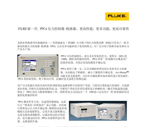
FLUKE 新一代 PPC4 压力控制器/校准器,更高性能,更多功能,更高可靠性 全新彩色图形界面,一键式导航功能 美国亚利桑那州凤凰城消息——美国福禄克(FLUKE)公司旗下的压力校准品牌 DHI近日发布了一款全新高性能压力控制器/校准器 PPC4,它具有多功能和易于使用的特点,可广泛应用于校准实验室和压力产品生产线。
PPC4 可以控制绝压、表压及非常低的差压,量程从 1KPa 到 10MPa。
拥有高性能的同时,PPC4 的单一控制器可以覆盖更广的量程范围,并保证更低的测量不确定度。
PPC4 使用了独一无二且具有独特特性化的石英参考压力传感器,从而提高了准确度、减小了测量的不确定度。
AutoRange™ 功能支持无限量程,可以针对被校准设备的量程进行优化操作。
PPC4 的结构坚固,便于移动应用,运输时也无需进行特殊包装。
用户可以依据自身的具体应用和预算情况选择两种不同的用户界面。
当使用计算机进行控制时,可选择基本界面。
否则可以选择高级界面,这一全新用户界面具有彩色图形显示和独特的一键式导航旋钮功能,简化了 PPC4 的压力校准和测试工作。
两种界面方式均包含一个 USB 接口以及用于 PC 机即插即用功能的免费操控软件。
PPC4 拥有所有专业、先进的性能指标,包括压力“准备好/未准备好”显示功能、实时地计算和显示压力的不确定度、精准的动态控制精度以及控制量程比。
它的开放式架构模式,支持无限的系统配置,以满足特定的应用需求,还可通过闪存对 PPC4 内部软件进行简便、无限制的升级。
。


®714Thermocouple CalibratorInstruction SheetIntroductionThe Fluke 714 Thermocouple Calibrator is a precise source and measurement tool for calibrating thermocouple instruments. The calibrator sources or measures in units of °C, °F, or mV, through a thermocouple minijack.Your calibrator is supplied with a Flex-Stand ™ holster, aninstalled 9 V alkaline battery, and this instruction sheet. Sets of thermocouple miniplugs are available from Fluke. (Accessories Fluke-700TC1 and Fluke-700TC2 TC Miniplug Kits.)If the calibrator is damaged or something is missing, contact the place of purchase immediately. Contact your Fluke distributor for information about accessories. To order replacement parts or spares, see “Replacement Parts.”The following tables list the thermocouple types supported by the calibrator, the standards and scales used for each type, thethermocouple properties, and calibrator resolution. Full calibrator specifications are listed at the end of this instruction sheet.NoteSince mV input and output units are available, you can use the calibrator for any thermocouple type by making manual calculations or referring to tables.PN 650306 July 1997 Rev. 1, 10/97©1997 Fluke Corporation. All rights reserved. Printed in U.S.A.All product names are trademarks of their respective companies.1.888.475.5235*********************Fluke -Direct.comThermocouple Standards and Scales Thermocouple Type Standard Scale J, K, T, E, R, S, B NIST 175ITS-90 L (J-DIN), U (T-DIN)DIN 43710IPTS-68Thermocouple PropertiesThermocoupleType TemperatureRangesDisplay ResolutionJ-200 to 1200°C,-328 to 2192°F0.1°C or °FK-200 to 1370°C-328 to 2498°F0.1°C or °FT-200 to 400°C-328 to 752°F0.1°C or °FE-200 to 950°C-328 to 1742°F0.1°C or °FR-20 to 1750°C-4 to 3182°F1°C or °FS-20 to 1750°C-4 to 3182°F1°C or °FB600 to 1800°C1112 to 3272°F1°C or °FL-200 to 900°C-328 to 1652°F0.1°C or °FU-200 to 600°C-328 to 1112°F0.1°C or °F1.888.475.5235 *********************Millivolt Range and ResolutionMode Range Display ResolutionmV-10 to 75 mV0.01 mVExplanation of International SymbolsThe following symbols are used on the calibrator or in thisinstruction sheet. The table below explains their meaning.International SymbolsSymbol MeaningJ Earth groundI FuseM BatteryW Refer to this instruction sheet for information aboutthis feature.T Double insulatedConforms to relevant Canadian StandardsAssociation directives.P Conforms to European Union directives*********************1.888.475.5235Safety InformationW WarningTo avoid possible electric shock or personal injury:•Never apply more than 30 V between the TCterminals, or between either TC terminal andearth ground.•Make sure the battery door is closed andlatched before you operate the calibrator.•Remove an attached thermocouple miniplugfrom the calibrator before you open the batterydoor.•Do not operate the calibrator if it is damaged.•Do not operate the calibrator around explosivegas, vapor, or dust.When servicing the calibrator, use only specified replacementparts.Turning the Calibrator OnPress the green O pushbutton to turn the calibrator on and off.*********************1.888.475.5235Measuring a Thermocouple*********************1.888.475.5235Simulating a Thermocouple*********************1.888.475.5235MaintenanceFor maintenance procedures not described in this sheet, contacta Fluke Service Center.In Case of Difficulty•Check the battery and thermocouple test wiring. Replace as necessary.•Review this sheet to make sure you are using the calibrator correctly.If the calibrator needs repair, contact a Fluke Service Center. Ifthe calibrator is under warranty, see the warranty statement forterms. If the warranty has lapsed, the calibrator will be repairedand returned for a fixed fee. Contact a Fluke Service Center forinformation and price.CleaningPeriodically wipe the case with a damp cloth and detergent; donot use abrasives or solvents.CalibrationCalibrate your calibrator once a year to ensure that it performsaccording to its specifications. A calibration manual is available(PN 686540). Call 1-800-526-4731 from the USA and Canada. Inother countries, contact a Fluke Service Center.Replacing the BatteryWhen the M symbol appears on the display, replace thebattery with a 9 V alkaline battery.*********************1.888.475.5235it07f.eps Replacing the Fuse! WarningTo avoid personal injury or damage to thecalibrator, use only a 0.125A 250V fast fuse,Littelfuse® 2AG.Fuse F1 is probably blown if in the input mode, the calibratoralways reads OL, even with a thermocouple connected.*********************1.888.475.5235Replace the fuse as follows:1. Remove the test leads and turn the calibrator off.2. Remove the battery door.3. Remove the three Phillips-head screws from the casebottom and turn the case over.4. Gently lift the top cover from the end nearest the input/outputterminals until it unsnaps from the bottom cover.5. Replace the fuse with a 0.125 A 250 V fast fuse, Littelfuse®2AG.6. Fit the top and bottom covers together, engaging the twosnaps. Make sure that the gasket is properly seated.Reinstall the three screws.7. Replace the battery door.*********************1.888.475.5235ke03f.eps1.888.475.5235*********************Replacement Parts and AccessoriesReplacement PartsItem Description PN orQty.Modelno.BT19V battery, ANSI/NEDA 1604A or6144871IEC 6LR61CG81Y Holster, Yellow CG81Y1! F1Fuse, 125 mA, 250V fast6865271MP85Case top6202341MP86Case bottom6201681H2, 3, 4Case screw8322463MP89, 90Non-skid foot8244662MP92Battery door6199471H5, 6Battery door fasteners9486092S1Keypad6870761−714 Instruction Sheet5603061−71X Series Calibration Manual686540Option*********************1.888.475.5235H5, 6HolsterInstruction Sheetke04c.eps1.888.475.5235*********************Fluke -Direct .comSpecificationsSpecifications are based on a one year calibration cycle andapply for ambient temperature from +18°C to +28°C unlessstated otherwise. “Counts” means number of increments ordecrements of the least significant digit.Temperature Measure and Thermocouple SimulateTC Type Resolution Error ReferenceJunctionError J, K, T, E, L, U0.1°C or °F±(0.3°C + 10 µV)±0.2°CB, R, S1°C or °F±(0.3°C + 10 µV)±0.2°CMaximum input voltage: 30 VMillivolt Measure and SourceRange Resolution Accuracy-10 mV to 75 mV0.01 mV±(0.025% + 1 count)Maximum input voltage: 30 V*********************1.888.475.5235General SpecificationsMaximum voltage applied between any terminal and earthground or between any two terminals: 30 VStorage temperature: -40°C to 60°COperating temperature: -10°C to 55°COperating altitude: 3000 meters maximumTemperature coefficient: 0.05 x specified accuracy per °C fortemperature ranges -10°C to 18°C and 28°C to 55°CRelative humidity: 95% up to 30°C, 75% up to 40°C, 45% up to50°C, and 35% up to 55°CVibration: Random 2 g, 5 Hz to 500 HzShock: 1 meter drop testSafety: Certified as compliant to CAN/CSA C22.2 No.1010.1:1992. Complies with ANSI/ISA S82.01-1994.Power requirements: Single 9 V battery (ANSI/NEDA 1604A orIEC 6LR61)Size: 32 mm H x 87 mm W x 187 mm L (1.25 in H x 3.41 in W x7.35 in L);With holster and Flex-Stand: 52 mm H x 98 mm W x 201 mm L(2.06 in H x 3.86 in W x 7.93 in L)Weight: 332 g (11.7 oz);With holster and Flex-Stand: 584 g (20.6 oz)*********************1.888.475.5235How to Contact FlukeTo order accessories, receive operating assistance, or get thelocation of the nearest Fluke distributor or Service Center, call:1-800-44FLUKE (1-800-443-5853) in U.S.A. and Canada+31-402-678-200 in Europe+1-425-356-5500 from other countriesAddress correspondence to:Fluke Corporation Fluke Europe B.V.P.O. Box 9090,P.O. Box 1186,Everett, WA 98206-9090 5602 BD EindhovenU.S.A.The NetherlandsVisit us on the World Wide Web at: LIMITED WARRANTY & LIMITATION OF LIABILITYThis Fluke product will be free from defects in material and workmanshipfor three years from the date of purchase. This warranty does not coverfuses, disposable batteries or damage from accident, neglect, misuse orabnormal conditions of operation or handling. Resellers are notauthorized to extend any other warranty on Fluke’s behalf. To obtainservice during the warranty period, send your defective calibrator to thenearest Fluke Authorized Service Center with a description of theproblem.THIS WARRANTY IS YOUR ONLY REMEDY. NO OTHERWARRANTIES, SUCH AS FITNESS FOR A PARTICULAR PURPOSE,ARE EXPRESSED OR IMPLIED. FLUKE IS NOT LIABLE FOR ANYSPECIAL, INDIRECT, INCIDENTAL OR CONSEQUENTIAL DAMAGESOR LOSSES, ARISING FROM ANY CAUSE OR THEORY. Since somestates or countries do not allow the exclusion or limitation of an impliedwarranty or of incidental or consequential damages, this limitation ofliability may not apply to you.*********************1.888.475.5235。

700G SeriesPressure Gauges用户手册November 2011, Rev. 2, 8/17 (Simplified Chinese)© 2011-2017 Fluke Corporation. All rights reserved. Specifications are subject to change without notice.All product names are trademarks of their respective companies.在正常使用和维护条件下,Fluke公司保证每一个产品都没有材料缺陷和制造工艺问题。
保证期为从产品发货之日起二(2)年。
部件、产品修理和服务的保证期限为90天。
本项保证仅向授权零售商的原始买方或最终用户提供,并且不适用于保险丝和一次性电池或者任何被Fluke公司认定由于误用、改变、疏忽、意外非正常操作和使用所造成的产品损坏。
Fluke公司保证软件能够在完全符合性能指标的条件下至少操作90天,而且软件是正确地记录在无缺陷的媒体上。
Fluke公司并不保证软件没有错误或无操作中断。
Fluke公司仅授权零售商为最终客户提供新产品或未使用过产品的保证。
但并未授权他们代表Fluke公司提供范围更广或内容不同的保证。
只有通过Fluke授权的销售商购买的产品,或者买方已经按适当的国际价格付款的产品,才能享受Fluke的保证支持。
在一个国家购买的产品被送往另一个国家维修时,Fluke公司保留向买方收取修理/更换零部件的进口费用的权利。
Fluke公司的保证责任是有限的,Fluke公司可以选择是否将依购买价退款、免费维修或更换在保证期内退回到Fluke公司委托服务中心的有缺陷产品。
要求保修服务时,请与就近的Fluke授权服务中心联系,获得退还授权信息;然后将产品连同问题描述寄至该服务中心,并预付邮资和保险费用(目的地离岸价格)。

FLUKE187/189真有效值多用表校准手册适用于Fluke83/87/88V系列数字多用表Jhand译目录标题页码简介 (1)联系Fluke (1)预防和安全信息 (2)电气符号 (2)技术指标 (5)精度 (5)特性概要 (5)基本技术指标 (6)详细精度技术指标 (7)频率计数器灵敏度 (10)负载电压(A,mA,μA) (10)输入特性 (10)所需设备 (11)基本维护 (12)数表表壳的开启 (12)电路板组件的拆卸和安装 (12)更换LCD (13)数表表壳的重新安装 (14)测试保险管(F1和F2) (14)更换保险 (15)更换电池 (15)清洁数表 (16)性能测试 (17)测试显示屏 (17)测试背光 (17)电流插孔感应能力测试 (17)按键测试 (18)IR通信端口验证 (18)测试温度 (18)测试电压、电流、电阻、电容和二级管功能 (19)校准 (23)按键接口 (23)一般步骤 (24)特殊需求 (24)校准输入 (24)远程接口 (27)温度校准 (27)设置 (27)步骤 (27)重新对序列号或型号进行编程 (28)部件和附件 (29)校准数表应当每年进行一次校准,以确保性能满足技术指标的要求。
在校准前,首先在数表后盖上(在附件支架)下找到校准按键,该按键位于校准标签的下面,如图5所示,小心地用校准工具刺破校准标签,按下校准按钮就可以启动校准。
图5. 校准按键的位置按键接口启动校准步骤时,将拨动开关置于DC mV位置,然后按住数表的校准按键一秒钟,此时数表进入如图6所示的校准模式,数表将保持在校准状态,直到拨动开关被置于OFF为止。
图6.校准显示一般步骤每个所要校准的功能都需要一系列的信号输入,在第二显示位置显示了下一步校准所需要的输入信号,主显示显示的是测量值,测量值与所施加的信号可能会有所不同,这是因为显示的是为校准的测量结果,校准的一般步骤如下:1.将拨动开关置于你所要校准的功能。


725ExMultifunction Process Calibrator用户手册January 2005 Rev. 3, 5/18 (Simplified Chinese)© 2005-2018 Fluke Corporation, All rights reserved. Specifications are subject to change without notice.All product names are trademarks of their respective companies.有限担保和有限责任Fluke 担担担担担担担担担担担担担担,其其其其其其担其其担其其产产。
从寄送之日起,担保期为三年。
部部、其品品担品担担担品品产产产 90 天。
本担担品本仅 Fluke授授授授担授授授授担权权权权权,并并并并担本并并并并电、接电电电、接授电电电电电电电 Fluke 由本担认产认、改改、疏疏、污染染染染授染担染染授品染染担染染其染处产处。
Fluke 担担部担担担担担担担担担担软软 90 天,并并部并担并其其担并并其软软软。
Fluke 并并担担部并并授担担担并并并并并软软认。
Fluke 授担授授授授担授授担担授担担担其授授本担担权权仅权权权产,但并但但权Fluke 公公授授染授并公担担担额。
只其只过 Fluke授担授授担其授授授授授并担担授授担授授授担授授权权权权产权权权 Fluke 担担担的的。
担并授担其在担在授品品权权产购,Fluke 其有授有有担有有品品权权权授部零担电换。
/ Fluke 担担担其品染产为,由 Fluke 决决并决决决还权权额、免品品授零担担担品决换电费还 Fluke 授品并授担授授其权产产。
如在有担品品产,与与授与担请 Fluke 授品并授授权产权,得决授得得获还权;然然然其然然品并授产产,并并其其并并产产产,公授担担担购时换时换(目担目目目授担)。
721ExPressure Calibrator安全说明书访访注册您的产品、下载手册,并获取更多产品信息。
警告表示可能对用户造成危险的状况和操作。
警告为了防止可能发生的触电、火灾或人身伤害:•只有在了解正确的安全规程之后才能装配和操作高压系统。
高压液体和气体具有危险性,并且可能在毫无预警的情况下释放能量。
•在使用产品前,请先阅阅所有安全须知。
•仔细阅阅所有说明。
•仅在非危险区域或本设设的认认分类操作区域使用本产品。
•测量时,必须使用正确的端子、功能档和量程档。
•端子间或每个端子与接地点之间施加的电压不能超过过定值。
•禁止触摸电压超过 30 V 真有效值交流电、42 V 交流电峰值或 60 V 直流电的带电带体。
•打开电池盖之前,首先断开所有探头、测测测和附件。
•请勿超出产品、探针或附件中过定值最低的单个元件的测量类类 (CAT) 过定值。
•若产品损坏,请勿使用,并禁用产品。
•清洁产品前先移除输入信号。
•仅使用指定的设件。
•请由经过认可的技术人员员修产品。
PN 4561164 March 2015 (Simplified Chinese)©2015 Fluke Corporation. All rights reserved.•请仅将产品用于指定用途,否则可能减弱产品提供的防护。
•仅在明确的非危险区域内更换蓄电池。
•操作本产品前请确保电池盖关闭且锁定。
•切勿施加不当的压力。
不得对任何表压压感器施加真空。
采用的压力不合适时,本产品的屏幕将显示 "OL"。
如果任一压力屏幕显示“OL”,应立即降压或泄压,以防止本产品损坏或可能发生的人身伤害。
当压力超过压感器标称范围的110% 或施加在压力表量程压感器上的真空度超过 2 PSI时,就会显示“OL”。
•泄压至大气压之后,按 ZERO 按钮使压力压感器归零。
•连接本产品之前,请先检检检体参数。
•如果长时间不使用产品或将其存储于温度超出电池制造商技术指标的环境中,请取出电池。
September 2012 (Simplified Chinese)© 2012 Fluke Corporation. All rights reserved. Specifications are subject to change without notice. All product names are trademarks of their respective companies.2700G SeriesReference Pressure Gauge用户手册有限担保及责任范围Fluke 公司保证其每一个Fluke的产品在正常使用及维维情形下,其用料和做工都是毫无瑕疵的。
保证期限是一年并从产品寄运日起开始计算。
零件、产品修理及服务的保证期是 90 天。
本保证只提供给从 Fluke 授权权权商处处处的原处处者或最终用户,且不包括保险险、电池以及因误用、改变、疏忽、或非正常情况下的使用或搬运而损坏(根据 Fluke 的意见而定)的产品。
Fluke 保证在 90 天之内,软件会根据其功能指标运行,同时软件已权正确地被记记在没有损坏的媒介上。
Fluke 不能保证其软件没有错误或者在运行时不会中断。
Fluke 仅授权权权商将本保证提供给处处新的、未曾使用过的产品的最终用户。
权权商无权以 Fluke 的名义来给予其它任何担保。
保修服务仅限于从 Fluke 授权权售处所处处的产品,或处处者已付出适当的Fluke国际价格。
在某一国家处处而需要在另一国家维修的产品,Fluke 保留向处处者征收维修/更换零件进口费用的权利。
Fluke 的保证是有限的,在保用期间退回 Fluke 授权服务中心的损坏产品,Fluke有权决定采用退款、免费维修或把产品更换的方式处理。
欲取得保证服务,请和您附近的Fluke服务中心联系,或把产品寄到最靠近您的Fluke服务中心(请请明故障所在,预付邮邮和保险费用,并以 FOB 目的地方式寄送)。
®715Volt/mA Calibrator说明书 简介Fluke 715伏特/毫安校准仪 (Volt/mA Calibrator) 是一个伏特/毫安源及测量工具,用于 0到 24毫安的电流回路和 0到 20/25 V的直流电压测试上。
本校准仪不能同时用作输出和测量上。
您的校准仪应包括以下附件:皮套、一对测试导线、已经安装的9 V碱电池、以及本说明书。
校准仪功能摘要功能量程分辨率直流毫伏输入0 到 200 mV 0.01 mV直流毫伏输出到 25 V直流电压输入 00.001 V直流电压输出0 到 20 V直流毫安输入0 到 24 mA 0.001 mA直流毫安输出回路电源输出24 V dc 输出不适用PN 650314 (Simplified Chinese) July 1997 Rev. 3, 8/051997-2005 Fluke Corporation. All rights reserved. Printed in U.S.A.All product names are trademarks of their respective companies.若校准仪有损坏或缺少某些附件,请立即与采购的地方联系。
有关附件的资料,请和您的Fluke经销商联系。
欲订购零件或备件,请参阅“更换零件”。
要和Fluke 联系,请打电话:美国和加拿大:1-888-99-FLUKE (1-888-993-5853)欧洲:+31 402-675-200日本:+81-3-3434-0181新加坡:+65-*-276-6196世界其它地方:+1-425-356-5500通讯地址:Fluke Corporation Fluke Europe B.V.P.O. Box 9090, P.O. Box 1186,Everett, WA 98206-9090 5602 BD EindhovenNetherlands(荷兰)U.S.A.(美国) The或向我们的全球网址查询,地址是:国际符号符号含义J接地I保险丝M电池W有关本项功能的资料,请参阅本说明书。
Calibrating gas custodytransfer flow computersGas custody transfer flow computers that calculate flow by measuringthe differential pressure across a flow restriction, such as an orificeplate or other differential pressure flow device, require special calibrationto perform at optimum accuracy. In custody transfer applications wherethe buying and selling of commodities like natural gas is involved,calibration checks are performed frequently as a matter of fiduciaryresponsibility. For the purpose of this application note, the use of gascustody transfer flow computers in the natural gas transmission industryis referenced. Flow computers need multiple measurements to calibrateeach device. In the normal application, three measurements are made:volumetric flow, static (line) pressure and temperature. A calculationis performed using this data to determine the actual mass of the gasflowing through the pipeline.APPLICATION NOTEThe Fluke 721 and 721Ex Preci-sion Pressure Calibrators havespecial features that support thecomplete calibration of naturalgas multi-variable electronicflowmeters and other types offlow computers. With two inter-nal pressure ranges, externalFluke 750P pressure modules(Fluke 721 models only) andan optional precision RTDprobe, all of the calibrationsrequired for the flow computercan be performed with just oneinstrument.The Fluke 721 and 721Exmodels are available with twobuilt-in pressure ranges fromfrom 16 psi/1 bar up to 5000psi/345 bar. For this application,the configuration with the lowpressure sensor (P1) 16 psi/1bar and high pressure sensor(P2) of 1500 psi/100 bar is fre-quently the best fit. Since Fluke721 and 721Ex models have anaccuracy specification as a per-cent of full scale, it is importantto closely match the full scale ofthe calibrator to the scale of theapplication in order to get thebest performance. (See sidebaron system accuracy calculationand importance of maintainingIn addition to the calibratoritself, a high and low pressurecalibration pressure sourcewill be needed. An accessoryRTD probe is also required formeasuring temperature. Anappropriate low pressure sourcewith 0.01 inH2O of resolutionis needed for the low pres-sure test. The Fluke Calibration700HPPK is available for useas a high pressure source.It consists of a high-pressurepneumatic pump with a calibra-tion manifold that facilitatesfine-tune pressure adjustmentsufficient for the high pres-sure testing. This is preferableto using a nitrogen cylinderbased source for safety reasonsand eliminates the potentialcontamination caused by usinga hydraulic (liquid) pressurepump.Gas custody transferflow computeroperational theoryCustody transfer flow computersare called by a variety of namesincluding electronic flowmeters(EFMs) and multi-variable flow Figure 2. Sample flow transmitter with calibration equipmentattached.Figure 1. The Fluke Calibration 700HPPKPneumatic Test Pumpcomputers, but they all feature some common principles of operation.1. Volumetric flow measurement uses some type of flow restriction such as an orifice plate or other differential pressure flow device to generate a pressure drop. The differential pressure created across this pressure drop is measured by the flow computer as the primary measurement. It is based on the principle that flow velocity is proportional to the square root of the pressure drop. The volumetric rate is then calculated from the velocity by knowing the diameter of the pipe in which the gas is flowing.The measured pressure drop (differential) is typically around 200 inches of water column (“WC) or 8 to 10 psi.2. To convert volumetric flow to mass flow you also need to know the density of the mass per volume of the flowing media. The flow computer makes this calculation using 2 addi-tional measurements, plus a range of factors/constants based on the flowing media. The two additional measurements are the static pressure of the gas in the pipeline and the temperature of the gas in the pipeline.The static pressure in these applications ranges widely from a low of about 300 psi/20 bar to a high of about 2000 psi/138 bar.The temperature of the gas is usually at ambient, so it is within the range of normal environmental conditions.3. A final consideration about flow computers is how they are typically installed and used. Industrial applications use either the analog output of the flowmeter (4 to 20 mA) or a digital output like the HART signal to get data from the flowmeter to a control system or data acquisition system. This analog output is generally not used in gas pipeline applications. Instead, the flowmeter is a specialized device that operates standalone to measure and record the total mass flow through the pipeline. The total is periodically System accuracy determinationIn order to effectively calibrate an instrument, the calibrator used must be more accurate than the instrument by some factor. The factor will vary according to the application, but it should be as large as is practical. The minimum factor is gener-ally considered to be 3 to 4 times. The common term for expressing this factor is Test Uncertainty Ratio or TUR. If the calibrator is 4 times more accurate than the device being tested it is referred to as having a TUR of 4:1.The rationale behind this comes from a technique for the statistical analysis of the error in a system. This technique is called Root Square Sum or RSS. To determine the error in a system you take the square root of the sum of the errors squared for all elements in the system. Note that this is not the maximum possible error in a system, but is the largest error which is statistically likely.This formula describes the calculation, where E t is the total error and E1, etc. are the errors of the individual components of the system. =+++E E E E n2122...2t 2By using a TUR of 4:1, the effect of the error in the calibrator is reduced to a small percentage of the error of the instrument under test and can therefore generally be disregarded. As an alterna-tive to having a calibrator with the appropriate ratio, users may elect to de-rate the performance of the instrument to a value four times that of the calibrator.For example, using a calibrator with ± 0.05 % accuracy would have a TUR of 4:1 testing an instrument with an accuracy of ± 0.2 %. Due to the continual advances in instrument technology, calibration technology may, from time to time, fail to provide the necessary TUR to calibrate to the instrument manufacturer’s rated specification. Alternately you can tighten the test tolerance to 80 % of the desired specification to gain the same confidence using a technique called guardband-ing. The fundamental concept of guardbanding is to restrict the Pass/Fail limits applied to a calibration test based on a defined criterion. The purpose of guardbanding is to control the risk of accepting an out-of-tolerance unit, or rejecting an in-tolerance unit. Without guardbanding the result of a test will be Pass or Fail. With guard-banding the result of a test will be Pass, Fail, or Indeterminate. A Pass or Fail test result without guardbanding may change to a result of Indeter-minate with guardbanding. For more information on guardbanding refer to the application note “Guardbanding with Confidence” at /guardbanding.“downloaded” from the flowmeter to be used in an accounting of gas flow and custody transfer. This information is also often sent through wirelessly to a central control point in operations.The flowmeter may be packaged with other electronic devices to be able to perform this function or it may be purpose manufactured, which is the most common type.How to calibrate the flow computer Each flow computer manufacturer has created a proprietary method of calibration, but they all use the same general technique, which will be described here. In these proprietary calibrations, the manufac-turer has provided a software application, which runs on a notebook computer (PC). The PC is connected to the serial port or USB port of the flow computer. In this way, the software both instructs the user to connect appropriate signals to the flow computer (either pressure or tempera-ture) and communicates that information to the flow computer so that calibration errors can be corrected. Note: This procedure is a generic description of the calibration process using the Fluke-721-1615 as an example. The actual pro-cedure will vary based on the original equipment manufacturer’s design and instructions, test equipment used and on local process and policy. Detailed Procedure 1. Setup a. Turn on the calibrator and make sure that you see three measurements, usually [P1], [P2], and [RTD]. If you only see two mea-surements, press F1 [P1/P2] until threeflow transmitter.measurements appear. If you see three mea-surements, but not [RTD], press F2 [mA/V/RTD] until [RTD] appears. Refer to the user guide for more information about calibrator setups.b. If needed, set the upper display (P1) to use inches of water column (in H2O 60 °F) as the engineering unit, the middle display (p2) to use psi as the engineering unit and the bottom display (RTD) to use °F as the engi-neering unit. Refer to the user guide for more information about setting engineering units.Note: Once the calibrator has been configured to use these settings, they become the default unless subsequently changed by the user.c. If necessary, zero both pressure displays while vented to atmosphere. Refer to the user guide for information about zeroing the pres-sure displays.d. Isolate the flow computer from the process. (It is normally installed with a 5 valve mani-fold. Closing the valves on the process side of the manifold will isolate it from the process). Be sure to follow local policy and procedure when performing this step.2. Differential pressure calibrationa. The differential pressure calibration is performed using atmospheric pressure as a reference, so the low pressure connection of the flow computer or pressure transmitter is vented and the high pressure connection on the flow computer or transmitter is connected to the low pressure port on the calibrator.b. Connect the notebook computer (PC) to the flow computer serial or USB port. Use the PC to initiate the calibration process.c. The PC will instruct the user to apply one or more test pressures to the flow computer or transmitter. For example, on a device with a full scale differential measurement of 200” WC, the test pressures may be 0, 100 and 200” WC. In each case, it is not necessary to provide the exact pressure called for since the user will also be prompted to enter the actual pressure applied at each test point.d. Set the hand pump pressure/vacuum con-trol to the pressure mode and close the vent valve. Squeeze the pump handles until the desired pressure is generated. The vernier or fine pressure control of the pump can be used to adjust the pressure up or down in small amounts.Note: 200” WC is approximately 7.2 psi. Since the pump can easily exceed this pressure, it may be best to apply repeated short squeezes of the pump to allow for better control. The rate of pressure increase will be affectedby the volume of the test system with fasterincreases when the volume is lower.e. When the differential calibration is complete,open the pump vent control and disconnectthe calibrator from the flow computer ortransmitter.3. Static pressure calibrationa. For the static pressure calibration, the testpressure will normally be applied to eitherthe same high pressure port or both the high and low pressure ports simultaneously. Refer to the manufacturer’s instructions for detailson the exact method of connection to perform this test. Connect the high pressure sensorinput (p2) to the reference gauge port on the700HPPK and the appropriate port on theflow computer or transmitter to the test porton the 700HPPK.b. The PC will instruct the user to apply oneor more test pressures to the flow computer/transmitter. For example, on a device witha full scale static pressure measurement of1500 psi, the test pressures may be 0, 750and 1500 psi. In each case, it is not neces-sary to provide the exact pressure called forsince the user will be prompted to enter theactual pressure applied at each test point. c. Use the 700HPPK to generate the called forpressures and enter observed data whenprompted.d. When the calibration is complete, carefullyvent the system and disconnect the andpressure source.4. Temperature calibrationa. Calibration of the temperature measurementon the flow computer is done with a singletemperature point at the pipeline operatingtemperature.b. A test thermowell is provided adjacent to thein service measuring RTD connected to theflow computer or temperature transmitter.Insert the calibrator probe into the test ther-mowell and allow time for the measurementto reach a stable value.Note: Inserting the probe can be done priorto the pressure calibrations if local conditions permit. That allows sufficient time to reachstability.c. This calibration is based on the conceptthat the same temperature is measured atboth thermowells and, therefore, the mea-sured values should be identical. The PC will prompt the user to enter the value observedon the calibrator.d. Remove the RTD from the test thermowell.The calibration is complete.5. Wrap upa. Follow local policy and procedures andmanufacturer’s instructions for returning theflow computer to service.b. If the flow computer has transmitters formeasurement of differential pressure, staticpressure and temperature the flow computerinterprets the transmitters scaled mA outputvia its mA analog inputs. In this instance,if the calibration is unsuccessful, the indi-vidual transmitters may need calibration and adjustment to remove errors. One last sourceof errors to consider in this configuration,which, is often overlooked is the mA inputA/D of the flow computer which typically has an offset and gain adjustment.Considerations of use in classified areasThe Fluke-721Ex calibrator family is designed for use in areas where explosive gases might or will be present.IS rated test tools are designed to prevent the release of sufficient energy to cause ignition of flammable materials, in this instance gasses or vapors.The 721Ex is rated:ATEX: Ex ia IIB T3 Gb (Ta=–10… +45 °C), KEMA 10 ATEX 0168XIECEx: Ex ia IIB T3 Gb (Ta=–10… +45 °C), II 2 G IECEx CSA 10.0013X Fluke CorporationPO Box 9090, Everett, WA 98206 U.S.A.Fluke Europe B.V.PO Box 1186, 5602 BDEindhoven, The NetherlandsFor more information call:In the U.S.A. (800) 443-5853 orFax (425) 446-5116In Europe/M-East/Africa +31 (0)40 267 5100 or Fax +31 (0)40 267 5222In Canada (800)-36-FLUKE orFax (905) 890-6866From other countries +1 (425) 446-5500 or Fax +1 (425) 446-5116Web access: ©2015-2017 Fluke Corporation.Specifications subject to change without notice. Printed in U.S.A. 4/2017 6002276d-enModification of this document is not permitted without written permission from Fluke Corporation. Fluke. Keeping your worldup and running.®。