
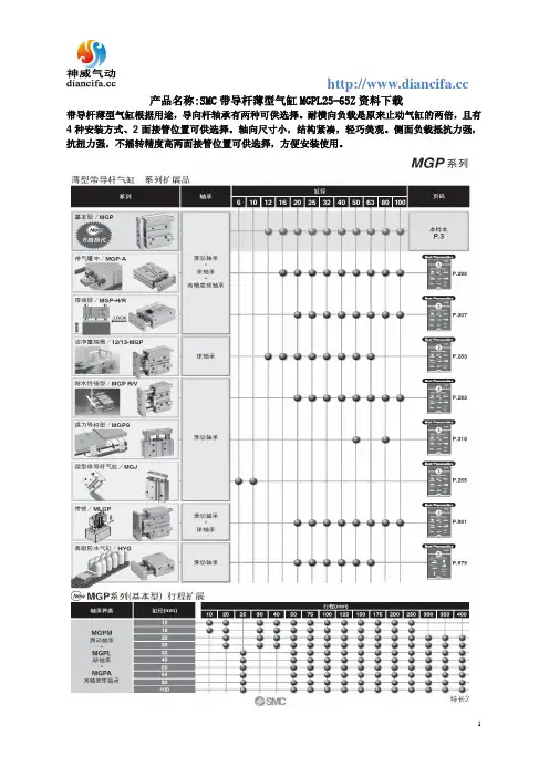
MGPL25-65Z资料下载
- 格式:doc
- 大小:1.75 MB
- 文档页数:5

CMOS Low Voltage2.5 Ω Dual SPDT SwitchADG736 Rev. CInformation furnished by Analog Devices is believed to be accurate and reliable. However, noresponsibility is assumed by Analog Devices for its use, nor for any infringements of patents or other rights of third parties that may result from its use. Specifications subject to change without notice. No license is granted by implication or otherwise under any patent or patent rights of Analog Devices. T rademarks and registered trademarks are the property of their respective owners. One Technology Way, P.O. Box 9106, Norwood, MA 02062-9106, U.S.A. Tel: 781.329.4700 Fax: 781.461.3113 ©2003–2007 Analog Devices, Inc. All rights reserved.FEATURES1.8 V to 5.5 V single supplyAutomotive temperature range: −40°C to +125°C 2.5 Ω(typical) on resistanceLow on resistance flatness−3 dB bandwidth > 200 MHzRail-to-rail operation10-lead MSOP packageFast switching timest ON: 16 nst OFF: 8 nsTypical power consumption (<0.01 μW)TTL-/CMOS-compatibleAPPLICATIONSUSB 1.1 signal switching circuitsCell phonesPDAsBattery-powered systemsCommunications systemsSample-and-hold systemsAudio signal routingAudio and video switchingMechanical reed relay replacement FUNCTIONAL BLOCK DIAGRAM46-1SWITCHES SHOWNFOR A LOGIC 1 INPUTS1AS1BD1IN1S2BIN2D2S2AFigure 1.GENERAL DESCRIPTIONThe ADG736 is a monolithic device comprising two independ-ently selectable CMOS single pole, double throw (SPDT) switches. These switches are designed using a submicron process that provides low power dissipation yet gives high switching speed, low on resistance, low leakage currents, and wide input signal bandwidth.The on resistance profile is very flat over the full analog signal range. This ensures excellent linearity and low distortion when switching audio signals. Fast switching speed also makes the part suitable for video signal switching.The ADG736 operates from a single 1.8 V to 5.5 V supply, making it ideally suited to portable and battery-powered instruments.Each switch conducts equally well in both directions when on, and each has an input signal range that extends to the power supplies. The ADG736 exhibits break-before-make switching action.The ADG736 is available in a 10-lead MSOP package. PRODUCT HIGHLIGHTS1. 1.8 V to 5.5 V Single-Supply Operation. The ADG736offers high performance, including low on resistance andfast switching times. It is fully specified and guaranteedwith 3 V and 5 V supply rails.2.Very Low R ON (4.5 Ω Maximum at 5 V, 8 Ω Maximum at 3 V).At a supply voltage of 1.8 V, R ON is typically 35 Ωover thetemperature range.3.Low On Resistance Flatness.4.−3 dB Bandwidth > 200 MHz.5.Low Power Dissipation. CMOS construction ensures lowpower dissipation.6.Fast t ON/t OFF.7.Break-Before-Make Switching Action.8.10-Lead MSOP Package.ADG736Rev. C | Page 2 of 12TABLE OF CONTENTSFeatures..............................................................................................1 Applications.......................................................................................1 General Description.........................................................................1 Functional Block Diagram..............................................................1 Product Highlights...........................................................................1 Revision History...............................................................................2 Specifications.....................................................................................3 Absolute Maximum Ratings............................................................5 ESD Caution..................................................................................5 Pin Configuration and Function Descriptions..............................6Typical Performance Characteristics..............................................7 Test Circuits........................................................................................9 Terminology....................................................................................10 Applications Information..............................................................11 Outline Dimensions.......................................................................12 Ordering Guide.. (12)REVISION HISTORY12/07—Rev. B to Rev. CUpdated Temperature Range (Throughout).................................1 Changes to Features Section............................................................1 Changes to Figure 4 and Figure 5...................................................7 Changes to Ordering Guide..........................................................12 1/07—Rev. A to Rev. BUpdated Format..................................................................Universal Changes to Leakage Currents.........................................................3 Changes to Leakage Currents.........................................................4 Changes to Ordering Guide..........................................................12 Updated Outline Dimensions.......................................................12 11/03—Rev. 0 to Rev. ARenumbered Figures and TPCs........................................Universal Change to Title..................................................................................1 Changes to Applications..................................................................1 Changes to Absolute Maximum Ratings.......................................4 Changes to Ordering Guide............................................................4 Changes to Test Circuit 3.................................................................7 Changes to Outline Dimensions.. (8)ADG736Rev. C | Page 3 of 12SPECIFICATIONSV DD = 5 V ± 10%, GND = 0 V . All specifications −40°C to +125°C, unless otherwise noted. Table 1.B VersionParameter25°C −40°C to +85°C −40°C to +125°CUnit Test Conditions/CommentsANALOG SWITCHAnalog Signal Range 0 V to V DD VOn Resistance (R ON ) 2.5Ω typV S = 0 V to V DD , I DS = −10 mA; see Figure 104 4.5 7 Ω max On Resistance Match Between Channels (∆R ON ) 0.1 Ω typ V S = 0 V to V DD , I DS = −10 mA 0.4 0.4 Ω maxOn Resistance Flatness (R FLAT (ON)) 0.5Ω typ V S = 0 V to V DD , I DS = −10 mA 1.2 1.5 Ω maxLEAKAGE CURRENTSV DD = 5.5 V Source Off Leakage I S (Off) ±0.011 nA typ V S = 4.5 V/1 V, V D = 1 V/4.5 V; see Figure 11Channel On Leakage I D , I S (On) ±0.01 5 nA typ V S = V D = 1 V or 4.5 V; see Figure 12DIGITAL INPUTSInput High Voltage, V INH 2.4 2.4 V min Input Low Voltage, V INL0.8 0.8 V maxInput Current, I INL or I INH 0.005μA typ V IN = V INL or V INH± 0.1 ± 0.1 μA max DYNAMIC CHARACTERISTICS 1t ON 12 ns typ R L = 300 Ω, C L = 35 pF 16 16 ns max V S = 3 V; see Figure 13 t OFF5 ns typ R L = 300 Ω, C L = 35 pF8 8 ns max V S = 3 V; see Figure 13 Break-Before-Make Time Delay, t D 7 ns typ R L = 300 Ω, C L = 35 pF1 1 ns min V S1 = V S2 =3 V; see Figure 14 Off Isolation –62 dB typ R L = 50 Ω, C L =5 pF, f = 10 MHz–82 dB typ R L = 50 Ω, C L = 5 pF , f = 1 MHz; see Figure 15Channel-to-Channel Crosstalk –62 dB typ R L = 50 Ω, C L = 5 pF, f = 10 MHz–82 dB typ R L = 50 Ω, C L = 5 pF , f = 1 MHz; see Figure 16Bandwidth (–3 dB) 200 MHz typ R L = 50 Ω, C L = 5 pF; see Figure 17 C S (Off) 9 pF typ C D , C S (On)32 pF typPOWER REQUIREMENTSV DD = 5.5 VI DD 0.001 μA typ Digital inputs = 0 V or 5 V1.01.0μA max1Guaranteed by design; not subject to production test.ADG736Rev. C | Page 4 of 12V DD = 3 V ± 10%, GND = 0 V . All specifications −40°C to +125°C, unless otherwise noted. Table 2.B VersionParameter25°C −40°C to +85°C −40°C to +125°C Unit Test Conditions/Comments ANALOG SWITCHAnalog Signal Range0 V to V DD VOn Resistance (R ON )55.5 Ω typ V S = 0 V to V DD , I DS = −10 mA; see Figure 108 12Ω max See Figure 10On Resistance Match Between Channels (∆R ON ) 0.1Ω typ V S = 0 V to V DD , I DS = −10 mA0.4 0.4Ω maxOn Resistance Flatness (R FLAT (ON)) 2.52.5Ω typV S = 0 V to V DD , I DS = −10 mA LEAKAGE CURRENTSV DD = 3.3 VSource Off Leakage I S (Off) ±0.01 1 nA typ V S = 3 V/1 V, V D = 1 V/3 V; see Figure 11Channel On Leakage I D , I S (On) ±0.015 nA typ V S = V D = 1 V or 3 V; see Figure 12DIGITAL INPUTSInput High Voltage, V INH 2.0 2.4 V min Input Low Voltage, V INL0.40.8 V maxInput Current, I INL or I INH0.005μA typ V IN = V INL or V INH±0.1 ± 0.1 μA max DYNAMIC CHARACTERISTICS 1t ON14ns typ R L = 300 Ω, C L = 35 pF2020ns max V S = 2 V; see Figure 13 t OFF6ns typ R L = 300 Ω, C L = 35 pF1010ns max V S = 2 V; see Figure 13 Break-Before-Make Time Delay, t D7ns typ R L = 300 Ω, C L = 35 pF11ns min V S1 = V S2 = 2 V; see Figure 14 Off Isolation−62 dB typ R L = 50 Ω, C L = 5 pF, f = 10 MHz−82 dB typ R L = 50 Ω, C L = 5 pF, f = 1 MHz; see Figure 15Channel-to-Channel Crosstalk−62 dB typ R L = 50 Ω, C L = 5 pF, f = 10 MHz−82 dB typ R L = 50 Ω, C L = 5 pF, f = 1 MHz; see Figure 16Bandwidth (−3 dB) 200MHz typ R L = 50 Ω, C L = 5 pF; see Figure 17 C S (Off) 9 pF typ C D , C S (On)32pF typPOWER REQUIREMENTSV DD = 3.3 VI DD 0.001 μA typ Digital inputs = 0 V or 3 V1.01.0μA max1Guaranteed by design; not subject to production test.ADG736Rev. C | Page 5 of 12ABSOLUTE MAXIMUM RATINGST A = 25°C, unless otherwise noted. Table 3.Parameter Rating V DD to GND −0.3 V to +6 V Analog, Digital Inputs 1−0.3 V to V DD + 0.3 V or 30 mA,whichever occurs firstContinuous Current, S or D 30 mA Peak Current, S or D 100 mA (Pulsed at 1 ms, 10%duty cycle maximum)Operating Temperature Range Automotive −40°C to +125°CStorage Temperature Range −65°C to +150°C Junction Temperature 150°C MSOP Package, Power Dissipation 315 mW θJA Thermal Impedance 205°C/WLead Temperature (Soldering,10 sec) 300°C IR Reflow (Peak Temperature,<20 sec)235°C Lead-Free Reflow Soldering Peak Temperature 260(+0/−5)°C Time at Peak Temperature 10 sec to 40 secESD 2 kV1Overvoltages at IN, S, or D are clamped by internal diodes. Current should be limited to the maximum ratings given.Stresses above those listed under Absolute Maximum Ratingsmay cause permanent damage to the device. This is a stress rating only; functional operation of the device at these or any other conditions above those indicated in the operationalsection of this specification is not implied. Exposure to absolute maximum rating conditions for extended periods may affect device reliability.ESD CAUTIONADG736Rev. C | Page 6 of 12PIN CONFIGURATION AND FUNCTION DESCRIPTIONS00046-002IN1S1A GND S2A IN2DDFigure 2. Pin ConfigurationTable 4. Pin Function DescriptionsPin No. MnemonicDescription1 IN1Logic Control Input.2 S1A Source Terminal. May be an input or output.3 GNDGround (0 V) Reference. 4 S2A Source Terminal. May be an input or output. 5 IN2 Logic Control Input.6 D2Drain Terminal. May be an input or output. 7 S2B Source Terminal. May be an input or output. 8 V DDMost Positive Power Supply Potential. 9 S1B Source Terminal. May be an input or output. 10 D1Drain Terminal. May be an input or output.Table 5. Truth TableLogic Switch A Switch B 0 Off On 1OnOffADG736Rev. C | Page 7 of 12TYPICAL PERFORMANCE CHARACTERISTICS6.05.55.04.54.03.53.02.52.01.51.00.5000.51.01.52.02.53.0 3.54.0 4.55.000046-003V D OR V S (DRAIN OR SOURCE VOLTAGE) (V)R O N (Ω)Figure 3. On Resistance as a Function of V D or V S Single Supplies6.05.55.04.54.03.53.02.52.01.51.00.5000.51.01.52.02.53.000046-004V D OR V S (DRAIN OR SOURCE VOLTAGE) (V)R O N (Ω)Figure 4. On Resistance as a Function of V D or V S for Different TemperaturesV DD = 3 V0.51.01.52.0 2.53.0 3.54.0 4.55.000046-005V D OR V S (DRAIN OR SOURCE VOLTAGE) (V)R O N (Ω)Figure 5. On Resistance as a Function of V D or V S for Different TemperaturesV DD = 5 V10m 1m100μ10μ1μ100n 10n 1n 00046-006FREQUENCY (Hz)I S U P P L Y (A )Figure 6. Supply Current vs. Input Switching FrequencyADG736Rev. C | Page 8 of 12–8–4–210k100M1M 10M 100k00046-007FREQUENCY (Hz)O N R ES P O N S E (d B )Figure 7. Bandwidth –30–130–120–110–100–90–80–70–60–50–4010k100M1M 10M 100k00046-008FREQUENCY (Hz)O F F I S O L A T I O N (d B)Figure 8. Off Isolation vs. Frequency–30–130–120–110–100–90–80–70–60–50–4010k100M1M 10M 100k00046-009FREQUENCY (Hz)C R OS S T A L K (d B )Figure 9. Crosstalk vs. FrequencyADG736Rev. C | Page 9 of 12TEST CIRCUITSV 00046-011Figure 10. On ResistanceV 00046-012Figure 11. Off LeakageV D00046-013Figure 12. On Leakage00046-014V V INV VFigure 13. Switching TimesV OUTV INV S50%50%0VV V V OUTV00046-01DV VFigure 15. Off Isolation00046-017VCHANNEL-TO-CHANNEL CROSSTALK = 20× LOG |V S /V OUT |VOUTFigure 16. Channel-to-Channel CrosstalkV VFigure 17. BandwidthADG736Rev. C | Page 10 of 12TERMINOLOGYR ONOhmic resistance between Terminal D and Terminal S. ΔR ONOn resistance match between any two channels; that is, R ON maximum − R ON minimum.R FLAT (ON)Flatness is defined as the difference between the maximum and minimum value of on resistance as measured over the specified analog signal range.I S (Off)Source leakage current with the switch off. I D , I S (On)Channel leakage current with the switch on. V D (V S )Analog voltage on Terminal D and Terminal S. C S (Off)Off switch source capacitance. C D , C S (On)On switch capacitance.t ONDelay between applying the digital control input and the output switching on. See Figure 13. t OFFDelay between applying the digital control input and the output switching off. See Figure 13.t DOff time or on time measured between the 90% points of both switches, when switching from one address state to another. See Figure 14.CrosstalkA measure of unwanted signal that is coupled from one channel to another as a result of parasitic capacitance.Off IsolationA measure of unwanted signal coupling through an off switch. BandwidthThe frequency at which the output is attenuated by −3 dB. On ResponseThe frequency response of the on switch.On LossThe voltage drop across the on switch, seen on the on response vs. frequency plot (see Figure 7) as how many decibels (dB) the signal is away from 0 dB at very low frequencies.ADG736Rev. C | Page 11 of 12APPLICATIONS INFORMATION00046-010L ΩFigure 18. Using the ADG736 to Select Between Two Video SignalsADG736Rev. C | Page 12 of 12OUTLINE DIMENSIONSCOMPLIANT TO JEDEC STANDARDS MO-187-BACOPLANARITY0.10Figure 19. 10-Lead Mini Small Outline Package [MSOP](RM-10)Dimensions shown in millimetersORDERING GUIDEModelTemperature Range Package DescriptionPackage Option Branding ADG736BRM−40°C to +125°C 10-Lead Mini Small Outline Package (MSOP) RM-10 SAB ADG736BRM-REEL −40°C to +125°C 10-Lead Mini Small Outline Package (MSOP) RM-10 SAB ADG736BRM-REEL7 −40°C to +125°C 10-Lead Mini Small Outline Package (MSOP) RM-10 SAB ADG736BRMZ 1−40°C to +125°C 10-Lead Mini Small Outline Package (MSOP) RM-10 SAB# ADG736BRMZ-REEL 1−40°C to +125°C 10-Lead Mini Small Outline Package (MSOP) RM-10 SAB# ADG736BRMZ-REEL71−40°C to +125°C 10-Lead Mini Small Outline Package (MSOP) RM-10 SAB#1Z = RoHS Compliant Part, # denotes RoHS compliant part may be top or bottom marked.©2003–2007 Analog Devices, Inc. All rights reserved. Trademarks and registered trademarks are the property of their respective owners. D00046-0-12/07(C)。


