DNV CAP UTM Specification
- 格式:pdf
- 大小:92.65 KB
- 文档页数:3
2. Approval Procedure认可程序2.1 Submission of documents提交的文件Application for approval should be sent to the local DNVoffice together with the following information: 包括下列资料的认可申请文件应提交当地DNV办公室:_ name and address of the manufacturer制造商的名称和地址_ a list of products for which approval is requested,认可的产品清单,包括钢种,制造方法,尺寸和交货状态including steel types, method of manufacture,dimensions and condition of supply_ an outline of the organisation structure including qualitycontrol responsibilities组织结构图,包括质量管理职责_ an outline of manufacturing facilities and equipment制造设施和设备清单_ manufacturing flow chart(s) indicating all process stepsand the associated testing and inspection points制造流程图,包括所有的制造工序和相关的试验和检验点_ reference to written procedures for testing andinspection. Procedures need not be submitted, but mustbe available for review at the manufacturer’s worksupon request引用书面的试验和检验程序。

第一部分1 A/B Above Base Line 基准线以上2 A/C Anticorrosive Paint 防腐涂料3 A/F Antifouling Paint 防污漆4 ABS American Bureau of Shipping 美国船级社5 Abt Abt (About ) 大约,关于6 ACCOM. Accommodation 船室,居住区7 Accommodation Ladder 舷梯8 ACCU Automatic control system certified for unattended eng. Room 无人机舱自动控制系统鉴定9 AFRAMAX Average Freight Rate Assessment at the max. of Deadweight 最大负载时平均运费率评估10 Bhd After Peak Bulkhead 船尖舱舱壁11 ANSI American National Standards Institute 美国国家标准协会12 AP After Perpendicular 艉垂线13 API American Petroleum Institute 美国石油组织14 APT After Peak Tank 尾尖舱15 ARPA Automatic Rader Plotting Aids 自动雷达测图仪16 ASTM American Society of Testing Materials 美国材料实验协会17 B mld Moulded Breadth 型宽18 B/C Bulk Carrier 散货船19 Base line 基线20 Basic Design 基本设计21 Ballast Control Room 压载控制室22 BHP Brake Horse Power 制动马力23 BOG Boil-off Gas 蒸发气体24 BOM Bill of Material 材料清单25 Bkt Bracket 支架,肘板26 BHD Bulkhead 隔壁, 防水壁27 C/H Cargo Hold 货舱28 Cable Trunk 电缆管道29 CCI Class Comment Item 船级社说明项目30 CCR Cargo Control ?31C, C/L Center Line 中心线32 Center of Gravity 重心33Cert. Certificate 证书34CFR Code of Federal Regulations 联合代码35CGT Compensated Gross Tonnage 补偿总吨36 Chain Locker 锚链舱37C/Eng. Chief Engineer 轮机长38C/D Cofferdam 隔离舱,围堰39COLREG International Regulations for Preventing Collisions at Sea 国际海上避碰规则40Corr. Bhd Corrugated Bulkhead 波形舱壁41COT Crude Oil Tanker 原油油船42 COT Cargo Oil Tank 货油舱43 CPU Central Processing Unit 中央处理器44 CRI Client Request Item 船东的要求项目45 Cyl. Liner Cylinder Liner 气缸套46 D mld Moulded Depth 型深47 D/B Double Bottom 双层底48 D/B Double Bottom Water Ballast Tank 双层底水压载舱49 Td Designed Load Draft 设计满载吃水50 DGPS Differential Global Positioning System 微型全球定位系统51 D/G Diesel Generator 柴油发电器(D/G)52 DLW Design Load Water Line 设计载重水线53 DNV Det Norske Veritas 挪威船级社54 DOT Diesel Oil 柴油55 DWT Deadweight Tonnage 载重量56 E/Rm Arr't Engine Room Arr't 机舱布置图57 ECR Engine Control Room 发动机控制台58 EHP Effective Horse Power 有效马力59 Elev. Elevation 侧面图60 Fab Fabrication 加工61 FEM Finite Element Method 有限单元法62 FEU Forty-Feet Equivalent Unit 40尺集装箱63 FOC Fuel Oil Consumption 燃料消耗量64 F'cle Dk Forecastle Deck 首楼甲板65 FP Fore Perpendicular 船首垂线66 FPP Fixed Pitch Propeller 定螺距螺旋浆67FPSO Floating Production,Storage and Offloading Vessel浮式生产储油卸油船68 FPT Forepeak Tank 首尖舱69 Fr. Frame 构架70 Frame Space 肋骨间隔71 FWT Fresh Water Tank 淡水舱72 G/A General Arrangement 总体布置图73 GL Germanisher Lloyd 德国船级74 GM Metacentric Height 稳心高度75 GMDSS Global Maritime Distress and Safety System ?全球海上遇险和安全系统76 GT Gross Tonnage 总吨数77 HFO Heavy Fuel Oil 重质燃油79 I/E Inclining Experiment 倾斜试验80 IACS International Association of Classification Socities ?国际船级联合会81 ICCP Impressed Current Cathodic Protection 外加电流阴极防护82 ID IdentificationNo. 身份证号码83 IEC International Electrotechnical Commission 国际电气标准会议84 IGC International Gas Code 国际气体代码85 ILLC International Load Line Convention 国际船舶载重线协定86 ILO International Labor Organization 国际劳动机构87 IMDG International Maritime Dangerous Goods Code ?国际海上危险物规定88 IMO International Maritime Organization 国际海上机构89 INMARSATInternational Maritime Satellite system国际海上卫星系统90 INS Integrated Navigation System 综合式集成导航系统91 IOPP International Oil Pollution Prevention Certificate ?国际防止原油污染证书92 ISO International Standardization Organization ?国际标准化机构93 ITU International Telecommunication Union 国际电子通信联盟94 JB Junction Box 接线盒,分线盒95 JIS Japanese Industrial Standard 日本标准工业规则96 K/L Keel Laying 铺设龙骨97 KR Korean Register of Shipping 韩国船级协会98 KS Korean Industrial Standard 韩国工业标准99 Kts Knots 节(船速)100L/C Launching 下水101LBP Length Between Perpendiculars 两柱间长102LCG Longitudinal Center of Gravity 纵方向上重心103LNG Liquified Natural Gas 液态天然气104LO Lubricating Oil 润滑油105LOA Length Over all 全长106Longl. BhdLongitudinal Bulkhead 纵舱壁107 Longitudinal Space 纵通材间隔108LPG Liquified Petroleum Gas 液化石油气109LR Lloyd's Register of Shipping 英国船级社110 Stor. TkLub. Oil Storage Tank 润滑油储存舱111M/V Motor Vessel 内燃机船112MARPOL The Prevention of Marine Pollution from Ships ?海洋防船舶污染113MDO Marine Diesel Oil 船用柴油114MEPC Maritime Environment Protection Committee ?海洋环境保护委员会115MMSI Maritime Mobile Service Identification No. ?海洋移动通信认证号116MSC Maritime Safety Committee 海事安全委员会117NK Nippon Kaiji Kyokai 日本船级社118NM Nautical Mile 海里(合公里)119NMD Norwegian Maritime Directorate 挪威海事高级别会议120NT Net Tonnage 净吨数121OBO Ore-Bulk-Oil Carrier 矿石散装油轮122OCIMF Oil Companies' International Maritime Forum ?油类公司的国际海事法庭123ODME Oil Discharge Monitoring Equipment 油泄监视设备124P & ID Piping and Instrumentation Diagram管路及仪器装设系统图125P/C Product Carrier 油船,成品油船126P/N Part Number 零件编号127PCC Pure Car Carrier 纯载车船128PO Purchase Order 订购单129POR Purchase Order Request 订购单要求130 Pre-Erection 先行合拢131PSC Port State Control 港口国管理132QCV Quick Closing Valve 速闭阀133R & D Research and Development 研究开发134RINA Registro Italiano Navale 意大利船级135Rise of Floor 船底倾斜度136RO/RO Roll-On/Roll-Off) Ship 滚装船137Rolling 横倾138RS Russia Register of Shipping 俄罗斯船舶检验局139SATCOM Satellite Communication 卫星通信140SBG See Berufasgenossenshaft 德国船舶安全事项检查机关141SC Steel Casting 铸钢件142Sec. Section 剖面图143SF Stowage Factor 积载因素144SHP Shaft Horse Power 轴马力145SLWL Summer Load Water Line 夏季满载吃水线146SNAME The Society of Naval Architects and Marine Engineers 造船与轮机工程师协会147SNMA Swedish National Maritime Administration 瑞典海事局148SOLAS (Safety of Life at Sea) Convention 海上人命安全公约149Spec. Specification 详细说明书150SPM Single Point Mooring 单点泊系151S/C Steel Cutting 切割刚材152S/G Rm Steering Gear Room 舵机室154stiff. Stiffener 加强件155Stri.) Stringer 纵梁(纵向加强肋,吊绳)156SUS Stainless Steel 不锈钢157SWBM Still Water Bending Moment 静水中弯曲力矩158SWL Safe Working Load 安全工作负荷159sym. Symmetrical 对称的160T/Top Tank Top 内底板液舱顶盖161TCG Transverse Center of Gravity 横向重心162TEU (Twenty-Feet Equivalent Unit) 20英尺集装箱163TPC Tonnes per Centimeter Immersion 每厘米吃水吨数164ULCC Ultra Large Crude Oil Carrier 300K ?超大型原油运输船(300K以上)165UMS Unattended Machinery Space 无人机械区166USCG United States Coast Guard 美国海岸警卫队167VCG Vertical Center of Gravity 垂直重心168V/D Vendor Drawing 制作者图纸169V/L Vertical Ladder 直梯170VLBC Very Large Bulk Carrier 超大型散货船171VLCC Very Large Crude Oil Carrier 超大型原油运输船172VRC Valve Remote Control 远距离控制阀173W-1 One-man Watch Keeping 一人持续操作174 Bhd Watertight Bulkhead 水密舱墙175WBT Water Ballast Tank 压载水舱第二部分ABS (American Bureau of Standard)美国船级社ANG (Angle Bar)角钢BFE (Builder Furnish Equipment)建造商提供设备BG (Bulk Carrier)散货船BHD (Bulkhead)舱壁BHP (Break Horsepower)制动马力BL (Base Line)基线BM (Breadth Molded)型宽BV (Bureau Veritas)法国船级社CAD (Computer Aided Design)计算机辅助设计CAM (Computer Aided Manufacturing)计算机辅助制造CB (Center of Buoyancy)浮心CCS (China Classification Society)中国船级社CF (Center of Floatation)漂心CFE (Contractor Furnish Equipment)承包商提供设备CG (Center of Gravity)重心CH (Channel)槽钢CM (Metacenter)稳心CPP (The Controllable Pitch Propeller)可调螺距桨CS (Carbon Steel)碳素钢DB (Double Bottom)双层底DK (Deck)甲板DM (Depth Molded)型深DNV (Det Norske Veritas)挪威船级社DWG (Drawing)图DWL (Design Waterline)设计水线DWT (Deadweight)载重量FAT (Factory Acceptance Test)工厂验收试验FB (Flat Bar)扁钢FEM (Finite Element Method)有限元法FPSO (Floating Production Storage Offloading) 浮(船)式生产储油卸油系统FSO (Floating Storage Offloading)浮(船)式储油卸油系统Fwd (Forward)向船艏GL (Germanischer Lloyd)德国船级社GM (Metacentric Height)初稳心高HP (Half Bulb Plate)球扁钢LBP (Length between Perpendiculars)垂线间长LCG (Longitudinal Center of Gravity)纵向重心LNG (Liquefied Natural Gas Vessel) 液化石油气船LOA (Overall Length)总长Long. (Longitudinal)纵骨LPG (Liquefied Petroleum Gas Vessel) 液化天然气船LR (Lloyd's Register)英国劳氏船级社MDK (Main Deck)主甲板MODU (Mobile Offshore Drilling Units)移动式近海钻井平台MS (Mild Steel)低碳钢MTO (Material Takeoff)材料估算NK (Nippon Kaiji Kyokai)日本海事协会OFE (Owner Furnished Equipment)船东提供设备OT (Oil Tight)油密PL (Plate)板RI (Register Italian)意大利船级社SB (Starboard)右舷Semi- (Semi-submersible Platform)半潜式钻井平台STLP (Suspended Tension Leg Platform)悬式张力腿平台TCG (Transverse Center of Gravity)横向重心TEU (Twenty-foot equivalent Unit)20英尺国际标准集装箱TLP (Tension Leg Platform)张力腿平台UCLL (Ultra Large Crude Carrier)超大型油船VCG (Vertical Center of Gravity)垂向重心VLCC (Very Large Crude Carrier)特大型油船WB (Web Bar)腹板WL (Waterline)水线WT (Water Tight)水密MECHANICAL & PIPING(轮机):AHU (Air Handling Unit)通风装置BHP (Break Horsepower)制动马力A/C (Air Compressor)空气压缩机A/C (Air Conditioning)空调BB (Ball Bearing)滚珠轴承BRG (Bearing)轴承CAS NUT(Castle Nut)蝶型螺帽CCR (Central Control Room)中心控制室COW (Crude Oil Washing)原油洗舱DFO (Diesel Fuel Oil)柴油DPS (Dynamic Position System)动力定位系统DT (Double-Thread)双头螺纹FS (Forged Steel)锻钢FW (Fresh Water)淡水FO (Fuel Oil)燃油GRP (Glass-reinforced Plastic)玻璃钢HVAV (Heating Ventilation and Air-condition)暖通空调系统HPU (Hydraulic Power Unit)液压工作站LSA (Life Saving Apparatus)救生器具LCC (Local Control Console)机旁控制台LO (Lube Oil)滑油MDO (Marine Diesel Oil)船用柴油OS (Operation System)操作系统PLC (Programmable Logic Controller)逻辑控制单元PMS (Power Manage System)动力管理系统ELECTRICAL(电气):AC (Alternative Current)交流电AVR (Automatic Voltage Regulation)自动电压调整计CCTV (Closed Circuit Television)闭路电视CMS (Cargo Monitoring System)货物监控系统DC (Direct Current)直流电DFT (Dry Film Thickness)干膜DG (Diesel Generator)柴油发电机DVD (Digital Video Disc) 数字化视频光盘EMSP (Emergency Shutter Panel)应急关断板ESS (Emergence Shutdown System)应急关闭系统GPS (Global Position System)全球定位系统HG (Harbor Generator)停泊发电机HT (High Temperature)高温JB (Junction Box)接线盒LED (Light Emitting Diode)发光二极管LT (Low Temperature)低温MCU (Main Control Unit)主控器箱MG (Main Generator)主发电机MUR (Manual Voltage Regulation)手动调压器NEMA (National Electrical Manufacturers Association) 国际电气制造业协会PA (Public Address System)公共寻呼系统PWM (Pulse Width Modulation)脉宽调制ST (Starter)启动器SWBD (Switch Board)配电盘,配电板UPS (Uninterrupted Power Supply)不间断电源VCR (Video Cassette Recorder)录像机PAINTING(涂装):ARD (Alkyd Resin Deck)醇酸树脂甲板漆ARF (Alkyd Resin Finish)醇酸树脂面漆ARP (Alkyd Resin Primer)醇酸树脂底漆A/C (Anti-corrosive Paint)防腐漆CAF (Compressed Asbestos Fiber)压缩石棉填料EDP (Epoxy Deck Paint)环氧甲板漆EFP (Epoxy Finish Paint)环氧面漆EPP (Epoxy Primer Paint)环氧底漆ETPF (Epoxy Tank Paint Finish)环氧舱室面漆ETPP (Epoxy Tank Paint Primer)环氧舱室底漆ETP (Epoxy Topside Paint)环氧干舷漆ERL (Erosion Resistant Lacquer)防腐漆ECP (Etching Primer) 磷化底漆EPR (Ethylene-Propylene Rubber)乙丙橡胶F/C (Finish Coating)面漆IZP (Inorganic Zinc Primer)无机锌底漆IZSP (Inorganic Zinc Shop Primer)无机锌车间底漆UTP (Polyurethane Topside Primer)聚氨脂干舷漆TE (Tar Epoxy Paint)环氧焦油漆VTP (Vinyl Tar Primer)聚乙烯焦油底漆ZRP (Zinc Rich Primer)富锌底漆WELDING and Material(焊接与材料)ASTM (American Society for Testing Materials)美国材料实验协会AWS (American Welding Society)美国焊接协会FCAW (Flux Cored Arc Welding)药芯焊丝电弧焊FRP (Fiberglass Reinforced Polyester)玻璃钢GMAW (Gas Metal Arc Welding)气体保护金属极电弧焊GRP (Glass Reinforced Polyester)玻璃钢GTAW (Gas Tungsten Arc Welding)气体保护钨极电弧焊GW (Gravity Welding)重力焊MPI (Magnetic Particle Inspection) 磁粒检验NDE (Nondestructive Evaluation)无损鉴定NDT (Nondestructive Testing)非破坏性检验PVC (Poly Vinyl Chloride)聚氯乙烯S/W (Spot Weld) 点焊SAW (Submerge Arc Welding)埋弧焊SMAW (Shielded Metal Arc Welding)手弧焊UT (Ultrasonic Test)超声波检验WPS (Welding Procedure Sheet)焊接程序表WQT (Welding Qualification Test)焊工资格检验OTHERS(其它):AE (Assistant Engineer)助理工程师ANSI (American National Standards Institute)美国国家标准局API (American Petroleum Institute)美国石油协会ASME (American Society of Mechanical Engineers)美国机械工程师协会Bbls (Barrels) 桶(美制容量单位 1桶 = 159升),. (Chief Engineer) 总工程师CEO (Chief Executive Officer)首席执行总裁CIS (Chinese Industrial Standard)中国工业标准CNOOC (China National Offshore Oil Company)中国海洋石油总公司Co Ltd.(Company Limited)(股份)有限公司. (Cubic Feet) 立方英尺. (Cubic Inch) 立方英寸GB (Guo Biao)国标GM (General Manage)总经理. (Headquarters) 总部HSE (Health, Safety & Environment)健康,安全和环保ID (Inner Dimension)内径IEC (International Electro technical Commission)国际电工协会IMO (Intergovernmental Marine Organization)国际海事组织ISO (International Standardization Organization)国际标准化协会ITU (International Telecommunication Union)国际电信联盟Ksi (kilopounds per square inch)千磅/平方英寸N/A (None Applicable)不适用NACE (National Association of Corrosion Engineer)全国防蚀工程师协会NFPA (National Fire Protection Association)国家防火协会OD (outer Dimension)外径QA (Quality Assurance)质量保证QC (Quality Control)质量管理(检查)ST (Short Ton)短吨SOLAS (International Convention of the Safety of Life at Sea)国际海上人命安全公约Spec. (specification)说明书,规格书. (Square Feet) 平方英尺. (Square Inch) 平方英寸PROPER NOUN(专有名词):Basic Design(基础设计): Preparation of specification and plans/drawings outlining the design and in sufficient detail to gain Class approval.总括性的设计规格书和图纸等,其详细程度仅足可以通过船级社认可其设计思想。
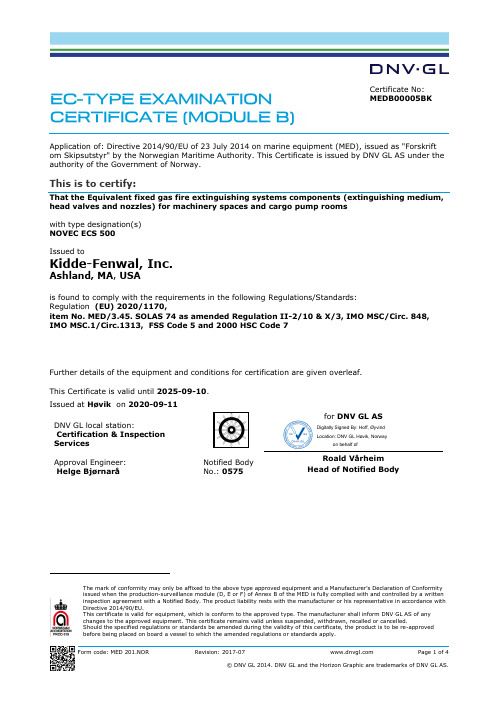
Form code: MED 201.NORRevision: 2017-07Page 1 of 4Certificate No: MEDB00005BKApplication of: Directive 2014/90/EU of 23 July 2014 on marine equipment (MED), issued as "Forskrift om Skipsutstyr" by the Norwegian Maritime Authority. This Certificate is issued by DNV GL AS under the authority of the Government of Norway.This is to certify:That the Equivalent fixed gas fire extinguishing systems components (extinguishing medium, head valves and nozzles) for machinery spaces and cargo pump roomswith type designation(s) NOVEC ECS 500Issued toKidde-Fenwal, Inc.Ashland, MA , USAis found to comply with the requirements in the following Regulations/Standards: item No. MED/3.45. SOLAS 74 as amended Regulation II-2/10 & X/3, IMO MSC/Circ. 848, IMO MSC.1/Circ.1313, FSS Code 5 and 2000 HSC Code 7Further details of the equipment and conditions for certification are given overleaf.This Certificate is valid until 2025-09-10.Issued at Høvik on 2020-09-11DNV GL local station:Certification & Inspection ServicesApproval Engineer: Helge BjørnaråNotified Body No.:0575for DNV GL ASRoald Vårheim Head of Notified BodyThe mark of conformity may only be affixed to the above type approved equipment and a Manufacturer’s Declaration of Conformit y issued when the production-surveillance module (D, E or F) of Annex B of the MED is fully complied with and controlled by a written inspection agreement with a Notified Body. The product liability rests with the manufacturer or his representative in accordance with Directive 2014/90/EU.This certificate is valid for equipment, which is conform to the approved type. The manufacturer shall inform DNV GL AS of any changes to the approved equipment. This certificate remains valid unless suspended, withdrawn, recalled or cancelled.Should the specified regulations or standards be amended during the validity of this certificate, the product is to be re-approved before being placed on board a vessel to which the amended regulations or standards apply.Digitally Signed By: Hoff, Øyvind Location: DNV GL Høvik, Norwayon behalf ofJob Id: 344.1-009310-1Certificate No: MEDB00005BK Product description“Novec ECS 500”,is a fixed gas fire extinguishing system using fire extinguishing agent Novec 1230 stored in steel cylinders as liquid and pressurized with nitrogen and distributed through pipes and nozzles.The extinguishing concentration and nozzles are covered by this type approval certificate. Documentation for the other system components shall be submitted and approved for each project. The system is to be designed in accordance with IMO MSC/Circ.848 as amended by IMO MSC.1/Circ.1267 and IMO MSC.1/Circ.1316.The extinguishing agent, Novec 1230, is produced by 3M, Cordova, Illinois, USA.2)When calculated at 20°C. Ambient temperature to be determined case by case for each project3)NFPA 2001 (2008 Edition)The following associated companies are authorised by Kidde-Fenwal to apply this certificate: -Kidde-Fenwal Inc., Ashland, USA-Kidde Fire Protection, Stokenchurch, UKApplication/LimitationThe design gas concentration (diesel) shall be minimum 5.85% (applied on a net volume) and the maximum agent discharge time shall be 10 seconds. The extinguishing system shall be designed and installed according to SOLAS Ch. II-2, IMO MSC/Circ.848 as amended by IMO MSC.1/Circ.1267, IMO MSC.1/Circ.1316 and the Kidde manual.The following additional limitations will apply:A.Novec ESC 500 systems are not suitable for the ship’s cargo holds. If Novec ESC 500 systemsare installed inside cargo pump rooms, all components shall be certified for use in hazardousareas, the design gas concentration shall be increased and the system is subjected to case bycase approval.B.If Novec 1230 agent is used above its NOAEL (calculated on net volume at max expectedambient temperature), means should be provided to limit exposure (IMO MSC.1/Circ.1267, 6).In no case should Novec 1230 be used in concentrations above its LOAEL.C.Steel storage cylinders of size 10 lb (4.5 kg) to 900 lb (408 kg). Cylinders being 81 L or larger isonly accepted when arrangements are provided on board to ensure that cylinders can be easily moved (even to shore) for service and recharging. All cylinders shall be of the same size.D.Gas cylinders shall be delivered on board with a product certificate of the Society or with acertificate issued by a recognized certification authority according to national regulations based on the requirements of the design standard and marked accordingly π, UN or DOT.E.Cylinders are topped up with nitrogen to 34.5 bar (500 psi) at 21°C. The fill density shall bemaximum 1.12 kg/L. Cylinders are to be delivered with DNV product certificate or equivalentcertificates acceptable to the flag administration and class.F.Cylinders to be located in a separate room in accordance with SOLAS Ch. II-2 Reg. 10.4.3, ordistributed throughout the protected space in accordance with the requirements in IMOMSC/Circ.848 item 11 as amended by IMO MSC.1/Circ.1267. When distributed within theprotected space, the min extinguishing concentration (after any single failure) shall be 4.5 %.Job Id: 344.1-009310-1Certificate No: MEDB00005BKponents in the system will be regarded under pressure class II with a maximum designpressure of 40 bar (at 54 °C). Consideration will though be made for piping and couplings inside the protected space.H.The nozzles are to be located in accordance with the Kidde manual. A basic rule is that onenozzle can as a maximum cover an area of 5 m x 10 m. A 360° nozzle shall be located centrally in this area, the 180° nozzles on the sides (as applicable). The maximum cover height is 5 m.The minimum average nozzle pressure is 4.2 bar.I.Bilges (except open bilges in small volume engine rooms) are to be protected with a dedicatednozzle network.The following documentation is to be submitted to the flag administration in each case:1.Plans showing location of cylinders, piping, nozzles and release stations as well as the assembledsystem2.Capacity calculations, including hydraulic flow calculations.3.Plans defining release lines and alarm system.4.Material specification and dimensions for piping and specifications for all other components.5.Ship specific release procedures and post discharge ventilation procedures.6.Manual containing design, inspection, operation and maintenance procedures.7.Control arrangements for closure of openings and stop of fans and any pressure relief devices asper IMO MSC/Circ. 848, 13. These plans can also be supplied by yard.Testing at installations and periodical surveys-The system shall be tested as per maker’s manual both at installations and at periodical surveys, except that DNV do not require monthly content check of cylinders. The minimum test pressure is minimum 53 bar for any closed sections, whereas open section shall be tightness tested atminimum 7 bar.-The system is subject to biennual (every 2nd year) inspections by an approved service supplier.The attending surveyor will also apply requirement relevant for flag administration and / or class on newbuilding and ship in operation surveys.Type Examination documentationDesign, Installation, Operation and Maintenance Manual – Novec ECS 500, No. P/N 06-237589-001, dated May 2017 from Kidde.Report No. HAI Project #5087, dated 28 June 2002, from Hughes Associates, Inc., Baltimore, USA. (tested on U.S. Coast Guard’s Fire & Safety Test Detachment in Mobile, AL).Report No. 04-CRADA-RDC-001, dated 16 November 2004, from Kidde-Fenwal Inc., Massachusetts, USA. (tested on U.S. Coast Guard’s Fire & Safety Test Detachment in Mobile, AL, witnessed by UL).Test Report File EX4674, Project 04NK23160, dated 1 February 2005, from UL, Northbook, USA.Report No. 3026502, dated 24 March 2006, from FM Approvals, Norwood, USA.Test report File EX4674, project 4788267101, dated 30 March 2018, from UL, Northbook, USAKidde Fenwal component sheets, stamped July 2005.Tests carried outTested in accordance with IMO MSC/Circ.848 as amended by IMO MSC.1/Circ.1267 and MSC.1/Circ.1316.Job Id: 344.1-009310-1Certificate No: MEDB00005BK Marking of productMain components in the system are to be marked with name and address of manufacturer, type designation and Mark of Conformity (see first page).。


RULES FOR CLASSIFICATION OFD ET N ORSKE V ERITASVeritasveien 1, NO-1322 Høvik, Norway Tel.: +47 67 57 99 00 Fax: +47 67 57 99 11SHIPSNEWBUILDINGSSPECIAL EQUIPMENT AND SYSTEMSADDITIONAL CLASS PART 6 CHAPTER 7DYNAMIC POSITIONING SYSTEMSJANUARY 2004This booklet includes the relevant amendments and correctionsshown in the July 2007 version of Pt.0 Ch.1 Sec.3.CONTENTS PAGESec.1General Requirements (5)Sec.2General Arrangement (11)Sec.3Control System (15)Sec.4Thruster Systems (18)Sec.5Power Systems (19)Sec.6Environmental Regularity Numbers (21)CHANGES IN THE RULESComments to the rules may be sent by e-mail to rules@For subscription orders or information about subscription terms, please use distribution@Comprehensive information about DNV and the Society's services is found at the Web site © Det Norske VeritasComputer Typesetting (FM+SGML) by Det Norske Veritas Printed in NorwayIf any person suffers loss or damage which is proved to have been caused by any negligent act or omission of Det Norske Veritas, then Det Norske Veritas shall pay compensation to such person for his proved direct loss or damage. However, the compensation shall not exceed an amount equal to ten times the fee charged for the service in question, provided that the maximum compen-sation shall never exceed USD 2 million.In this provision "Det Norske Veritas" shall mean the Foundation Det Norske Veritas as well as all its subsidiaries, directors, officers, employees, agents and any other acting on behalf of Det Norske Veritas.General.The present edition of the rules includes additions and amendments decided by the board in November 2003, and supersedes the January 2003 edition of the same chapter.The rule changes come into force on 1 July 2004.This chapter is valid until superseded by a revised chapter. Supple-ments will not be issued except for an updated list of minor amend-ments and corrections presented in Pt.0 Ch.1 Sec.3. Pt.0 Ch.1 is normally revised in January and July each year.Revised chapters will be forwarded to all subscribers to the rules.Buyers of reprints are advised to check the updated list of rule chap-ters printed Pt.0 Ch.1 Sec.1 to ensure that the chapter is current.Main changes—Steering gears shall be designed for continuous operation whenthey form part of the DP-system. Testing requirements to steer-ing gear shall also be specified.—The specific requirement for certification of UPS used for DPcontrol systems is removed. Certification of UPSs now shall fol-low main class requirements in Pt.4 Ch.8 Electrical Systems.—Requirement for certification of the independent joystick systemrequired for notations DYNPOS-AUT , DYNPOS-AUTR and DYNPOS-AUTRO introduced.—The new rules give opening for one of the three gyros requiredfor notation DYNPOS-AUTR and DYNPOS-AUTRO to be re-placed by a heading device based upon another principle, as longas this heading device is type approved as a THD (Transmitting Heading Device) as specified in IMO Res. MSC.116 (73).—The possibility for letting the independent joystick system use the same redundant network as the DP control system is re-moved. In the new rules the independent joystick system may share the communication link with the manual control, but not with the DP-control system.—More specific requirements to the effect of failures in the inde-pendent joystick control system.—Power supply for the independent joystick system is now re-quired to be independent of the DP control system UPSs.—The input power supply to the redundant UPSs is now required derived from different sides of the main switchboard.—Specification of power supply arrangement for position reference systems (PRS). The requirement is now that the power supply shall be in line with the overall redundancy requirements. PRSs shall still be powered from UPS.—The requirement for full separation between fuel oil systems de-signed with redundancy for notation DYNPOS-AUTR is clari-fied.—The new rules require FMEAs for Power Management Systems.—Requirement for DP-Control centre arrangement and layout doc-umentation is introduced.Corrections and ClarificationsIn addition to the above stated rule requirements, a number of correc-tions and clarifications have been made in the existing rule text.Amended,Rules for Ships, January 2004see Pt.0 Ch.1 Sec.3, July 2007 Pt.6 Ch.7 Contents – Page 3D ET N ORSKE V ERITASCONTENTSSEC. 1GENERAL REQUIREMENTS.......................... 5A.The Rules. (5)A 100Rule application................................................................5A 200Class notations..................................................................5A 300Environmental regularity number, ern .. (5)B.Definitions (5)B 100General..............................................................................5C.Certification...........................................................................6C 100General (6)D.Documentation (6)D 100General..............................................................................6D 200ern calculation..................................................................6D 300Instrumentation and automation .......................................6D 400Thruster documentation....................................................7D 500Electric power system documentation..............................7D600DP-Control centre arrangement andlayout documentation........................................................7D 700Failure mode and effect analysis (FMEA)........................7D 800Operation manuals............................................................8D 900Programme for tests and trials (9)E.Survey and Test upon Completion (9)E 100General..............................................................................9E 200Measuring system.............................................................9E 300Thrusters ...........................................................................9E 400Electric power supply........................................................9E 500Independent joystick thruster control system....................9E 600Complete DP-system test..................................................9E 700Redundancy tests for DYNPOS-AUTR andDYNPOS-AUTRO ..........................................................9F.Alterations. (10)F 100Owner obligations (10)SEC. 2GENERAL ARRANGEMENT......................... 11A.General (11)A 100General (11)B.Redundancy and Failure Modes (11)B 100General............................................................................11B 200Redundancy.....................................................................11B 300Failure modes..................................................................11B 400Independence..................................................................11B500General separation requirements forDYNPOS-AUTRO (11)C.System Arrangement (12)C 100General............................................................................12C 200DP-control centre............................................................12C 300Arrangement of positioning control systems..................13C 400Arrangement and layout of control panels......................13C 500Arrangement and layout of data communication links (13)D.Internal Communication (14)D 100General (14)SEC. 3CONTROL SYSTEM ....................................... 15A. General Requirements (15)A 100General (15)B.System Arrangement (15)B 100Independent joystick thruster control system.................15B 200DP-control system...........................................................15B 300Thruster control mode selection.. (15)C.Positioning Reference System (15)C 100General (15)D.Sensors (16)D 100General............................................................................16E.Display Units.. (17)E 100General (17)F.Monitoring (17)F 100Alarm system..................................................................17F 200Consequence analysis (17)SEC. 4THRUSTER SYSTEMS.................................... 18A.General.. (18)A 100Rule application..............................................................18A 200Thruster configuration....................................................18A 300Thruster control...............................................................18A 400Indication (18)SEC. 5POWER SYSTEMS........................................... 19A.General.. (19)A 100General............................................................................19A 200Number and capacity of generators................................19A 300Power management (for DYNPOS-AUTR andDYNPOS-AUTRO ).......................................................19A 400Main and distribution switchboards arrangement (19)B.Control System Power Supply (applies to DYNPOS-AUT , DYNPOS-AUTR and DYNPOS-AUTRO ) (20)B 100General (20)C.Auxiliary Systems (Applies toDYNPOS-AUTR and DYNPOS-AUTRO ) (20)C 100General............................................................................20C 200Fuel oil............................................................................20C 300Cooling water (20)SEC. 6ENVIRONMENTAL REGULARITYNUMBERS.......................................................... 21A.Concept Description.. (21)A 100General (21)Rules for Ships, January 2004Amended, Pt.6 Ch.7 Contents – Page 4see Pt.0 Ch.1 Sec.3, July 2007D ET N ORSKE V ERITASAmended,Rules for Ships, January 2004see Pt.0 Ch.1 Sec.3, July 2007 Pt.6 Ch.7 Sec.1 – Page 5D ET N ORSKE V ERITASSECTION 1GENERAL REQUIREMENTSA. The RulesA 100Rule application101 The rules in this chapter apply to systems for dynamic positioning of ships and mobile offshore units, termed hereaf-ter as, vessels. These rules do not include requirements or rec-ommendations in regard to the vessels operation or other characteristics.Guidance note:Requirements, additional to these rules may be imposed by the national authority with whom the vessel is registered and/or by the administration within whose territorial jurisdiction it is in-tended to operate. Where national legislative requirements exist,compliance with such regulations shall also be necessary.---e-n-d---of---G-u-i-d-a-n-c-e---n-o-t-e---102 The requirements in these rules are additional to the rules for main class.Guidance note:In particular see the relevant sections of:Pt.4 Ch.1 Machinery Systems, General Pt.4 Ch.2 Rotating Machinery, General Pt.4 Ch.3 Rotating Machinery, DriversPt.4 Ch.4 Rotating Machinery, Power Transmissions Pt.4 Ch.5 Rotating Machinery, Driven Units Pt.4 Ch.8 Electrical InstallationsPt.4 Ch.9 Instrumentation and Automation.---e-n-d---of---G-u-i-d-a-n-c-e---n-o-t-e---A 200Class notations201 Vessels built and tested in compliance with the require-ments in this chapter and the requirements of the rules for main class may be assigned one of the class notations given in Table A1.Guidance note:IMO MSC/Circ.645 "Guidelines for vessels with dynamic posi-tioning systems", dated 6 June 1994, has defined equipment classes with the following correlation to these rules:---e-n-d---of---G-u-i-d-a-n-c-e---n-o-t-e---A 300Environmental regularity number, ern301 Vessels with one of the class notations listed in 201 will be given an environmental regularity number (ern). It will be entered as a notation in the "Register of vessels classed with DNV" as ern(a, b, c) where a, b, c are integer numbers re-flecting probable regularity for keeping position in a defined area. See Sec.6 for details on the ern concept.B. DefinitionsB 100General101 Consequence analysis: An automatic monitoring func-tion in the DP-control system, checking the ability of the vessel to maintain position under current weather conditions if the worst case single failure should occur.Guidance note:For detailed information and requirements to the consequence analysis function see Sec.3 F200.---e-n-d---of---G-u-i-d-a-n-c-e---n-o-t-e---102 DP-control system: All control systems and compo-nents, hardware and software necessary to dynamically posi-tion the vessel. The DP-control system consists of the following:—dynamic positioning control system (computer system)—sensor system—display system (operator panels)—positioning reference system—associated cabling and cable routing.Guidance note:The DP-control system will normally consist of one or more computers. This is often referred to as the DP-system, but is only a part of the DP-system by rule terminology.---e-n-d---of---G-u-i-d-a-n-c-e---n-o-t-e---103 Dynamic positioning system (DP-system): The complete installation necessary for dynamically positioning a vessel comprises of the following systems:—power system —thruster system —DP-control system—independent joystick system (when applicable).104 Dynamically positioned vessel (DP-vessel): A vessel which automatically maintains its position (fixed location or predetermined track) exclusively by means of thruster force.Guidance note:In this context thruster force may include propulsion and steeringTable A1 Class notations Notation Scope DYNPOS-AUTS dynamic positioning system without redun-dancy DYNPOS-AUT dynamic positioning system with an inde-pendent joystick system back-up and a posi-tion reference back-up DYNPOS-AUTR dynamic positioning system with redundancyin technical design and with an independent joystick system back-upDYNPOS-AUTRO dynamic positioning system with redundancyin technical design and with an independent joystick system back-up. Plus a back-up dy-namic positioning control system in an emer-gency dynamic positioning control centre, designed with physical separation for compo-nents that provide redundancyDNV class notation IMO equipment class DYNPOS-AUTS Not applicableDYNPOS-AUT IMO equipment class 1DYNPOS-AUTR IMO equipment class 2DYNPOS-AUTRO IMO equipment class 3Rules for Ships, January 2004Amended,Pt.6 Ch.7 Sec.1 – Page 6 see Pt.0 Ch.1 Sec.3, July 2007D ET N ORSKE V ERITAS(rudder) forces, see Sec.4.---e-n-d---of---G-u-i-d-a-n-c-e---n-o-t-e---105 Failure: An occurrence in a component or system caus-ing one or both of the following effects:—loss of component or system function—deterioration of functional capability to such an extent thatthe safety of the vessel, personnel, or environment is sig-nificantly reduced.Guidance note:For vessels that shall comply with DYNPOS-AUTRO require-ments, the definition of single failure has no exceptions, and shall include incidents of fire and flooding, and all technical break-downs of systems and components, including all electrical and mechanical parts. Loss of stability (e.g. as a result of flooding) is not a relevant failure mode.For vessels that shall comply with DYNPOS-AUTR require-ments, certain exceptions will be allowed in the definition of sin-gle failure. Flooding and fire shall not be considered beyond main class requirements. Failure of non-moving components,e.g. pipes, manual valves, cables etc. may not need to be consid-ered if adequate reliability of a single component can be docu-mented, and the part is protected from mechanical damage.---e-n-d---of---G-u-i-d-a-n-c-e---n-o-t-e---106 Joystick: A device for readily setting of vectorial thrust output including turning moment.107 Operational mode: The manner of control under which the DP-system may be operated, e. g.:—automatic mode (automatic position and heading control)—joystick mode (manual position control with selectable au-tomatic or manual heading control)—manual mode (individual control of pitch and speed, azi-muth, start and stop of each thruster)—autotrack mode (considered as a variant of automatic posi-tion control, with programmed movement of reference point).108 Position keeping: Maintaining a desired position within the normal excursions of the control system and the environ-mental conditions.109 Positioning reference system: All hardware, software and sensors that supply information and or corrections neces-sary to give position and heading reference, including power supply.110 Power system: All components and systems necessary to supply the DP-system with power. The power system includes:—prime movers with necessary auxiliary systems includingpiping —generators —switchboards—uninterruptible power supplies (UPS) and batteries —distribution system including cabling and cable routing —for DYNPOS-AUTR and DYNPOS-AUTRO : powermanagement system (PMS).111 Redundancy: The ability of a component or system to maintain or restore its function when one failure has occurred.Redundancy can be achieved, for instance, by installation of multiple components, systems or alternative means of per-forming a function.112 Reliability: The ability of a component or system to per-form its required function without failure during a specified time interval.113 Thruster system: All components and systems necessary to supply the DP-system with thrust force and direction. The thruster system includes:—thruster with drive units and necessary auxiliary systemsincluding piping —thruster control—associated cabling and cable routing—main propellers and rudders if these are under the controlof the DP-system.114 Worst case failure: Failure modes related to the class no-tations as follows:—for DYNPOS-AUTS and DYNPOS-AUT , loss of posi-tion may occur in the event of a single fault—for DYNPOS-AUTR , loss of position is not to occur inthe event of a single failure as specified in Sec.2 B301—for DYNPOS-AUTRO , loss of position is not to occur inthe event of a single failure as specified in Sec.2 B302.C. CertificationC 100General101 The following equipment in the DP-system shall be cer-tified:—dynamic positioning control system—independent joystick control system with auto heading.Other equipment in the DP-system shall be certified according to relevant parts of Pt.4 as for main class.Guidance note:Additionally, components and systems should be certified ac-cording to main class requirements.---e-n-d---of---G-u-i-d-a-n-c-e---n-o-t-e---D. DocumentationD 100General101 The documentation submitted, shall include descriptions and particulars of the vessel and cover the requirements given in 200 to 700, as appropriate.D 200ern calculation201 Calculation of the environmental regularity number evaluation, ern , shall be submitted for approval. The position holding performance shall be quantified according to the con-cept for ern , see Sec.6.D 300Instrumentation and automation301 For general requirements related to documentation of in-strumentation and automation, including computer based con-trol and monitoring, see Pt.4 Ch.9 Sec.1.Guidance note:For description of documentation types, see Pt.4 Ch.9 Sec.1. Ta-ble C1 and C2.---e-n-d---of---G-u-i-d-a-n-c-e---n-o-t-e---302 For the control systems listed, documentation shall be submitted according to Table D1:DYN Dynamic positioning control and monitoring system JOY Independent joystick system TCM Thruster control mode selection PRS Position reference system(s)VEO Wind, VRS and gyroPMSPower Management System.D 400Thruster documentation401 Documentation shall be submitted as required for mainAmended,Rules for Ships, January 2004see Pt.0 Ch.1 Sec.3, July 2007 Pt.6 Ch.7 Sec.1 – Page 7D ET N ORSKE V ERITASclass.402 The following shall be submitted for information:—thrust output and power input curves —response time for thrust changes—response time for direction changes for azimuth thrusters —anticipated thrust reductions due to interaction effects.D 500Electric power system documentation501 Documentation shall be submitted as required for main class.502 Electrical load calculation during dynamic positioning operation shall be submitted for approval. For vessels with the notations DYNPOS-AUTR and DYNPOS-AUTRO the load calculations shall also reflect the situation after the maximum single failure(s).Guidance note:This documentation may be a part of the power consumption bal-ance as required in Pt.4 Ch.8 Electrical Installations.---e-n-d---of---G-u-i-d-a-n-c-e---n-o-t-e---503 For vessels with the notation DYNPOS-AUTRO , the following shall be submitted for approval:—cable routing layout drawing—fire and flooding separation arrangement.Guidance note:For the cable routing layout drawing it is recommended that col-ours are used to indicate the cable routes that are designed and physically arranged to provide redundancy.---e-n-d---of---G-u-i-d-a-n-c-e---n-o-t-e---Guidance note:The cable routing layout drawing shall indicate all cables rele-vant to the DP system, e.g. power cables, control cables, cables used for indication etc.---e-n-d---of---G-u-i-d-a-n-c-e---n-o-t-e---D 600DP-Control centre arrangement and layout docu-mentation601 For notations DYNPOS-AUTS , DYNPOS-AUT ,DYNPOS-AUTR and DYNPOS-AUTRO drawings showing the physical arrangement and location of all key components in the DP-control centre shall be submitted.602 For notation DYNPOS-AUTRO drawings showing the physical arrangement and location of all key components in the emergency DP-control centre shall be submitted.D 700Failure mode and effect analysis (FMEA)701 For vessels with the notations DYNPOS-AUTR and DYNPOS-AUTRO , documentation of the reliability of the dynamic positioning system is required in the form of a failure mode and effect analysis (FMEA).702 The purpose of the FMEA shall give a description of the different failure modes of the equipment when referred to its functional task. Special attention shall be paid to the analysis of systems that may enter a number of failure modes and thus induce a number of different effects on the dynamic position-ing system performance. The FMEA shall include at least the information specified in 703 to 705.703 A breakdown of the dynamic positioning system, into functional blocks shall be made. The functions of each block shall be described. The breakdown shall be performed to such a level of detail that the functional interfaces between the func-tional blocks are shown.704 A description of each physically and functionally inde-pendent item and the associated failure modes with their fail-ure causes related to normal operational modes of the item shall be furnished.705 A description of the effects of each failure mode alone on other items within the system and on the overall dynamic positioning system shall be made.Guidance note:Description of FMEA systematic may be found in IEC Publica-tion 60812 and IMO HSC Code, Annex 4.---e-n-d---of---G-u-i-d-a-n-c-e---n-o-t-e---706 FMEA(s) and redundancy test program(s) shall be kept on board. The FMEA(s) and redundancy test program(s) shall at all times be updated to cover alterations to the DP-system hardware or software.Guidance note:This is not to be understood as a requirement for an FMEA for the software. However the FMEA (or other relevant documenta-tion) should include identification of the software version(s) in-stalled, and documentation giving this information should be updated when new versions are installed.---e-n-d---of---G-u-i-d-a-n-c-e---n-o-t-e---Rules for Ships, January 2004Amended,Pt.6 Ch.7 Sec.1 – Page 8 see Pt.0 Ch.1 Sec.3, July 2007D ET N ORSKE V ERITASD 800Operation manuals801 Operation manuals according to Table D1 shall be kept on board. The manuals shall include information on the DP-system, its installation and structure as well as operation and maintenance.Guidance note:These manuals cover the technical systems. Manuals for DP op-erations are not normally included and may be produced sepa-rately, according to operational requirements.---e-n-d---of---G-u-i-d-a-n-c-e---n-o-t-e---802 They shall at least cover the following:—definitions of symbols and nomenclature—functional description—operating instructions, normal conditions —operating instructions, failure conditions —man and machine communication systems —back-up systems —monitoring—maintenance and periodical performance test —fault-finding procedures.Functional description—different functions including back-up functions shall beexplained in detail.Table D1 Requirements for documentation of instrumentation systemsD010D020D030D040D050D060***)D070D080D090D100D110D120D130D140D150D160For class notation DYNPOS-AUTS :DYN X X X X X X X **)**)**)**)X X *),**)TCM X X X X X X **)**)X PRS X X X X X *),**)VEO X X X X X For class notation DYNPOS-AUT :DYN X X X X X X X **)**)**)**)X X *),**)JOY X X X X X **)X *),**)TCM X X X X X X **)**)X PRS X X X X X *),**)VEO X X X X X For class notation DYNPOS-AUTR :DYN X X X X X X X X **)**)**)**)X X *),**)JOY X X X X X **)X *),**)TCM X X X X X X X **)**)X PRS X X X X X *),**)VEO X X X X X PMS ****)*),**)For class notation DYNPOS-AUTRO :DYN X X X X X X X X X **)**)**)**)X X *),**)JOY X X X X X **)X *),**)TCM X X X X X X X X **)**)X PRS X X X X X X *),**)VEO X X X X X XPMS ****)*),**)Instrumentation systems:Documentation types:DYN Dynamic positioning control and monitoring system JOY Independent joystick system TCM Thruster control mode selection PRS Position reference system(s)VEO Wind, VRS and gyro PMS Power Management System ****)D010 System philosophy (T)D020 Functional description D030 System block diagrams (T)D040 User interface documentation D050 Power supply arrangement (T)D060 Circuit diagramsD070 Instrument and equipment list (T)D080 Cable routing layout drawing (T)D090 Failure mode and effect analysis (FMEA) and redundancy test procedure (T)D100 Software quality plan, based upon life cycle activities D110 Installation manual D120 Maintenance manualD130 Data sheets with environmental specifications D140 Test program for testing at the manufacturer (T)D150 Test program for quay/sea trial (T)D150 Operation manual(T)Required also for type approved systems.*)One copy shall be submitted to approval centre for information only.**)Shall be available during certification and trials. Reference is made to Pt.4 Ch.9. Not to be submitted to the approval centre.***)For essential hardwired circuits (for emergency stop, shutdown, interlocking, mode selection systems, back-up selection systems,etc.). Details of input and output devices and power source for each circuit.****)FMEA for PMS systems is in addition to requirements given in Pt.4 Ch.9.Amended,Rules for Ships, January 2004see Pt.0 Ch.1 Sec.3, July 2007 Pt.6 Ch.7 Sec.1 – Page 9D ET N ORSKE V ERITASOperating instructions—description of the normal operation of the equipment, in-cluding adjustments and change of limit values, possible modes of presentation, starting and stopping systems —description of operation of the DP-system in different op-erational modes—description of transition from one operational mode to an-other.Fault-finding procedures—description of fault symptoms with explanation and rec-ommended corrective actions—instructions for tracing faults back to functional blocks orsystems.D 900Programme for tests and trials901 A programme for tests and trials including redundancy tests shall be submitted for approval. The requirements for the programme are described in E.E. Survey and Test upon CompletionE 100General101 Upon completion, the dynamic positioning system shall be subjected to final tests. The program shall contain test pro-cedures and acceptance criteria.Guidance note:It is assumed that prior to the DP-control system test, all systems and equipment included in the dynamic positioning system have been tested according to main class. This should at least include:-load test according to main class -transfer of thruster control-manual override of thruster control -emergency stop -“ready” signals-failure in thruster command/feedback signals -communication systems-main alarm system as for main class and E0 (if applicable).---e-n-d---of---G-u-i-d-a-n-c-e---n-o-t-e---E 200Measuring system201 All sensors, peripheral equipment, and reference sys-tems shall be tested as part of the complete DP-system.202 Failures of sensors shall be simulated to check the alarm system and the switching logic.E 300Thrusters301 Functional tests of control and alarm systems of each thruster shall be carried out.302 All signals exchanged between each thruster and the DP-system computers shall be checked.303 The different modes of thruster control shall be tested.Proper operation of mode selection shall be verified.E 400Electric power supply401 The capacity of the UPS batteries shall be tested.E 500Independent joystick thruster control system501 All functions of the independent joystick system shall be tested.E 600Complete DP-system test601 The complete DP-system shall be tested in all operation-al modes, with simulation of different failure conditions to tryout switching modes, back-up systems and alarm systems.602 Positioning shall be performed on all possible combina-tions of position reference systems (PRS), and on each PRS as a single system. Selecting and de-selecting of PRS shall also be tested.603 During sea trials the offset inputs for each position ref-erence system and relevant sensors in the dynamic position control system should be verified and demonstrated to the at-tending surveyor by setting out the offsets on drawings. It should be verified that these fit with the actual placing of the equipment.604 Manual override, as required by Sec.3 B202 and Sec.4A302 shall be demonstrated during normal operation and fail-ure conditions.605 A duration test shall be carried out for at least 8 hours with the complete automatic system in operation. All failures shall be recorded and analysed.Guidance note:The time spent on DP operational tests may normally be deduct-ed from the time required for the duration test.---e-n-d---of---G-u-i-d-a-n-c-e---n-o-t-e---606 A high seas trial shall be carried out with full system op-eration for at least 2 hours. The weather conditions must be such that an average load level on the thrusters of 50% or more is required.Guidance note:The test described in 606 is dependent on weather conditions and may be omitted if satisfactory results were obtained from the test described in 605.---e-n-d---of---G-u-i-d-a-n-c-e---n-o-t-e---607 For steering gears included under DP-control a test shall be carried out verifying that maximum design temperature of actuator and all other steering gear components is not exceeded when the rudder is continuously put over from border to border within the limits set by the DP-control system, until tempera-ture is stabilized.Guidance note:The test should be carried out with the propeller(s) running with an average propulsion thrust of not less than 50%, unless the con-trol system ensures that rudder operation is performed at zero propulsion thrust only, upon which the test may be carried out without the propeller(s) running. The test may be carried out at the quay and in any steering gear control mode. Number of steer-ing gear pumps connected and rotation speed are to be the maxi-mum allowed during DP operation.---e-n-d---of---G-u-i-d-a-n-c-e---n-o-t-e---E 700Redundancy tests for DYNPOS-AUTR and DYN-POS-AUTRO701 A selection of tests within each system analysed in the FMEA shall be carried out. Specific conclusions of the FMEA for the different systems shall be verified by tests when redun-dancy or independence is required.702 The test procedure for redundancy shall be based on the simulation of failures and shall be performed under as realistic conditions as practicable.。
营运船舶的船体测厚工作浅析发布时间:2022-10-27T03:33:31.524Z 来源:《科学与技术》2022年12期6月作者:何志强[导读] 船体测厚是现代船舶和海洋工程装置船体检验的一个重要组成部分何志强中兴海陆工程有限公司摘要:船体测厚是现代船舶和海洋工程装置船体检验的一个重要组成部分,是船舶生命周期安全监控的重要手段。
本论文对各个船检社测厚规则标准,腐蚀量对比,测厚的设备和测厚数据分析进行深入浅出的论述。
关键词:船级社测厚规范,腐蚀极限,超声波测厚1、概述海洋资源丰富,海洋运输是各个国家交流的桥梁,开发海洋是每个靠海国家的经济发展的方向。
海洋船舶数量和载重吨位每年在不断的提高,根据克拉克森的最新报告,到2021年2月,全球船队船舶数量(100GT以上)超过10万艘,海洋工程装置也不断的增多。
测厚是现代船舶和海洋工程装置船体检验的一个重要组成部分。
对测厚数据按照不同的规则进行统计计算和分类审查,是船舶生命周期安全监控的重要手段。
不同的公约和标准对测厚的位置和数据限值提出了不同的要求,本论文对各个船检社测厚规则标准,腐蚀量对比,测厚的设备和测厚数据分析进行深入浅出的论述。
为了促进海上安全标准的提高,增进海上人命安全,联合国和其他国际组织的有关公约、规则、规定和协定如:(国际船级社协会IACS;国际海事组织IMO;《海上人命安全公约》SOLAS;《国际防止船舶造成污染公约》MARPOL;《联合国海洋法公约》UNCLOS;欧洲海事安全局EMSA。
这些组织和船舶的船旗国对船舶的安全提出了不同的要求,以便对船舶和海洋工程装置进行安全监督和指导。
在上述组织派遣检验人员进行检查时,测厚是现代船舶和海洋工程装置船体检验的主要辅助手段。
2、测厚工作的准备船舶测厚开工前,必须召开船东或机务,船检,测厚人员在场的三方会议,明确以下情况:(1)船舶计划和测厚计划;(2)根据船龄和船舶类型确定测厚检验范围;(3)测厚条件和安全保障(人员安全、接近的方式、清洁和除锈、照明、通风等);(4)测厚有关图纸准备;(5)查阅相应规范允许的腐蚀余量;(6)根据上一次检验,确定近观检验和测厚范围及是否有上一次检验的备忘;(7)验船师、船东代表和测厚人员之间的联系方式;(8)当测厚人员测厚过程应该关注以下船舶状况,并及时告知船东和相关检验人员,包括有:1)超差或显著腐蚀或严重的点腐蚀和凹槽腐蚀时;2)结构缺陷时(如屈曲、开裂和变形等);3)构件脱开和穿孔时;4)焊缝腐蚀时。
Valid from September 2011 (current)PDF EditionSummary and Status Choices (top of page)Changes Summary of changes and current document status September 2011 RevNote: "Summary of changes" replaces "Amendments and Corrections" as of October 2010.Service Specifications Choices (top of page)DNV-DSS-314 Verification of Hydrocarbon Refining and Petrochemical Facilities October 2010 DNV-DSS-315 Verification of Onshore LNG and Gas Facilities October 2010Offshore Service Specifications Choices (top of page)DNV-OSS-101 Rules for Classification of Offshore Drilling and Support Units April 2011DNV-OSS-102 Rules for Classification of Floating Production, Storage and Loading Units April 2011 DNV-OSS-103 Rules for Classification of LNG/LPG Floating Production and Storage Units or Installations June 2011DNV-OSS-121 Classification Based on Performance Criteria Determined from Risk Assessment Methodology October 2008DNV-OSS-201 Verification for Compliance with Norwegian Shelf Regulations April 2010DNV-OSS-202 Verification for Compliance with UK Shelf Regulations April 2011DNV-OSS-300 Risk Based Verification April 2004DNV-OSS-301 Certification and Verification of Pipelines October 2000DNV-OSS-302 Offshore Riser Systems October 2010DNV-OSS-304 Risk Based Verification of Offshore Structures October 2006DNV-OSS-305 Rules for Certification and Verification of Diving Systems October 2010DNV-OSS-306 Verification of Subsea Facilities June 2004DNV-OSS-307 Verification of Process Facilities June 2004DNV-OSS-308 Verification of Lifting Appliances for the Oil and Gas Industry October 2010DNV-OSS-312 Certification of Tidal and Wave Energy Converters October 2008DNV-OSS-313 Pipe Mill and Coating Yard - Qualification April 2009DNV-OSS-401 Technology Qualification Management October 2010Standards Choices (top of page)DNV-DS-J102 Design and Manufacture of Wind Turbine Blades, Offshore and Onshore Wind Turbines November 2010Offshore Standards Choices (top of page)DNV-OS-A101 Safety Principles and Arrangements April 2011DNV-OS-B101 Metallic Materials April 2009DNV-OS-C101 Design of Offshore Steel Structures, General (LRFD Method) April 2011DNV-OS-C102 Structural Design of Offshore Ships April 2011DNV-OS-C103 Structural Design of Column Stabilised Units (LRFD Method) October 2009DNV-OS-C104 Structural Design of Self-Elevating Units (LRFD Method) April 2009DNV-OS-C105 Structural Design of TLPs (LRFD Method) April 2011DNV-OS-C106 Structural Design of Deep Draught Floating Units/Spars (LRFD and WSD Method) October 2009DNV-OS-C107 Structural Design of Ship-shaped Drilling and Well Service Units October 2009 DNV-OS-C201 Structural Design of Offshore Units (WSD Method) April 2011DNV-OS-C301 Stability and Watertight Integrity April 2011DNV-OS-C401 Fabrication and Testing of Offshore Structures October 2010DNV-OS-C501 Composite Components October 2010DNV-OS-C502 Offshore Concrete Structures October 2010DNV-OS-C503 Concrete LNG Terminal Structures and Containment Systems October 2010DNV-OS-D101 Marine and Machinery Systems and Equipment October 2010DNV-OS-D201 Electrical Installations April 2011DNV-OS-D202 Automation, Safety, and Telecommunication Systems October 2008DNV-OS-D203 Integrated Software-Dependent System (ISDS) June 2011DNV-OS-D301 Fire Protection October 2009DNV-OS-E101 Drilling Plant October 2009DNV-OS-E201 Oil and Gas Processing Systems October 2010DNV-OS-E301 Position Mooring October 2010DNV-OS-E302 Offshore Mooring Chain October 2009DNV-OS-E303 Offshore Mooring Fibre Ropes October 2010DNV-OS-E304 Offshore Mooring Steel Wire Ropes October 2009DNV-OS-E401 Helicopter Decks April 2011DNV-OS-E402 Offshore Standard for Diving Systems October 2010DNV-OS-E403 Offshore Loading Buoys October 2008DNV-OS-E406 Design of Free Fall Lifeboats April 2010DNV-OS-F101 Submarine Pipeline Systems October 2010DNV-OS-F201 Dynamic Risers October 2010DNV-OS-J101 Design of Offshore Wind Turbine Structures September 2011 RevDNV-OS-J201 Offshore Substations for Wind Farms October 2009DNV-OS-J301 Standard for Classification of Wind Turbine Installation Units April 2011Recommended Practices Choices (top of page)DNV-RP-A201 Plan Approval Documentation Types – Definitions April 2011DNV-RP-A203 Qualification of New Technology July 2011DNV-RP-A204 Quality Survey Plan (QSP) for Offshore Class New-building Surveys September 2011 NewDNV-RP-B101 Corrosion Protection of Floating Production and Storage Units April 2007DNV-RP-B401 Cathodic Protection Design April 2011DNV-RP-C101 Allowable Thickness Diminution for Hull Structure of Offshore Ships April 2007 DNV-RP-C102 Structural Design of Offshore Ships February 2002DNV-RP-C103 Column-Stabilised Units October 2010DNV-RP-C104 Self-elevating Units April 2011DNV-RP-C201 Buckling Strength of Plated Structures October 2010DNV-RP-C202 Buckling Strength of Shells October 2010DNV-RP-C203 Fatigue Design of Offshore Steel Structures April 2010DNV-RP-C204 Design against Accidental Loads October 2010DNV-RP-C205 Environmental Conditions and Environmental Loads October 2010DNV-RP-C206 Fatigue Methodology of Offshore Ships October 2010DNV-RP-C207 Statistical Representation of Soil Data October 2010DNV-RP-D101 Structural Analysis of Piping Systems October 2008DNV-RP-D201 Integrated Software Dependent Systems October 2009DNV-RP-E101 Recertification of Well Control Equipment October 2008DNV-RP-E102 Recertification of Blowout Preventers and Well Control Equipment for the US Outer Continental Shelf June 2010DNV-RP-E301 Design and Installation of Fluke Anchors in Clay May 2000DNV-RP-E302 Design And Installation of Plate Anchors in Clay December 2002DNV-RP-E303 Geotechnical Design and Installation of Suction Anchors in Clay October 2005DNV-RP-E304 Damage Assessment of Fibre Ropes for Offshore Mooring April 2005DNV-RP-E307 Dynamic Positioning Systems - Operation Guidance January 2011DNV-RP-E401 Survey of Diving Systems April 2007DNV-RP-E402 Naval Rescue Submersibles October 2010DNV-RP-E403 Hyperbaric Evacuation Systems October 2010DNV-RP-F101 Corroded Pipelines October 2010DNV-RP-F102 Pipeline Field Joint Coating and Field Repair of Linepipe Coating May 2011DNV-RP-F103 Cathodic Protection of Submarine Pipelines by Galvanic Anodes October 2010 DNV-RP-F105 Free Spanning Pipelines February 2006DNV-RP-F106 Factory Applied External Pipeline Coatings for Corrosion Control May 2011DNV-RP-F107 Risk Assessment of Pipeline Protection October 2010DNV-RP-F108 Fracture Control for Pipeline Installation Methods Introducing Cyclic Plastic Strain January 2006DNV-RP-F109 On-Bottom Stability Design of Submarine Pipelines October 2010DNV-RP-F110 Global Buckling of Submarine Pipelines Structural Design due to High Temperature/High Pressure October 2007DNV-RP-F111 Interference Between Trawl Gear and Pipelines October 2010DNV-RP-F112 Design of Duplex Stainless Steel Subsea Equipment Exposed to Cathodic Protection October 2008DNV-RP-F113 Pipeline Subsea Repair October 2007DNV-RP-F116 Integrity Management of Submarine Pipeline Systems October 2009DNV-RP-F118 Pipe Girth Weld AUT System Qualification and Project Specific Procedure Validation October 2010DNV-RP-F201 Design of Titanium Risers October 2002DNV-RP-F202 Composite Risers October 2010DNV-RP-F203 Riser Interference April 2009DNV-RP-F204 Riser Fatigue October 2010DNV-RP-F205 Global Performance Analysis of Deepwater Floating Structures October 2010DNV-RP-F206 Riser Integrity Management April 2008DNV-RP-F301 Subsea Separator Structural Design April 2007DNV-RP-F302 Selection and use of Subsea Leak Detection Systems April 2010DNV-RP-G101 Risk Based Inspection of Offshore Topsides Static Mechanical Equipment October2010DNV-RP-G103 Non-Intrusive Inspection January 2011DNV-RP-H101 Risk Management in Marine and Subsea Operations January 2003DNV-RP-H102 Marine Operations during Removal of Offshore Installations April 2004DNV-RP-H103 Modelling and Analysis of Marine Operations April 2011DNV-RP-H104 Ballast, Stability, and Watertight Integrity - Planning and Operating Guidance September 2011 NewDNV-RP-J101 Use of Remote Sensing for Wind Energy Assessments April 2011DNV-RP-J201 Qualification Procedures for CO2 Capture Technology April 2010DNV-RP-J202 Design and Operation of CO2 Pipelines April 2010DNV-RP-O401 Safety and Reliability of Subsea Systems April 1985DNV-RP-O501 Erosive Wear in Piping Systems November 2007[View archive by document]。
THICKNESS MEASUREMENT SPECIFICATION FOR DNV CONDITION ASSESSMENT PROGRAMME (CAP) HULL1. Objective1.1This specification describes the extent of thickness measurements required for DNVCondition Assessment Programme (CAP) Hull. Requirements to thickness measurementsfor class surveys are specified in DNV Rules for Classification of Ships.1.2DNV uses thickness measurement data for a statistical analysis of diminution as a basisfor the CAP rating. Representative data for all main structural elements in alltanks/spaces are required. The main structural elements in a CAP context are deck,shipside, bottom, inner bottom, inner deck, longitudinal bulkhead, transverse bulkhead(i.e. tank/space boundaries with plating and stiffeners) and internal structure (i.e.webframes, stringers, girders, floors etc.)1.3Failure to carry out thickness measurements according to this specification may preventcompletion of CAP.2. General2.1Thickness measurements shall be carried out by a qualified company approved by DNV.2.2A DNV surveyor shall be onboard while the measurements are taken to the extentnecessary to control the process.2.3The thickness measurements data shall be reported using the “DNV UTM Template”. Allinformation required in the template is to be completed by the thickness measurementcompany. The “DNV UTM Template” is available at 2.4One electronic version and one paper version of the thickness measurement report withsketches and relevant documentation is to be submitted to the responsible DNV unit.2.5Readings to be included in the thickness measurement report shall be representative forthe area measured and shall normally be single point readings. If a single reading is notconsidered to be representative for the area it represent, additional readings may becarried out in same area and included in the report together with a comment stating thatthese are additional readings. Alternatively, the average value of several readings in asmall area may be included in the report together with a comment stating that this is anaverage value. In such cases all the readings to be averaged are to be taken within theaffected area. Low readings shall not be averaged out by several readings in adjacentuncorroded areas.2.6Pits, grooves and local corrosion are to be measured and included in the report with asuitable comment.2.7Cracks, buckling and other deficiencies identified are to be reported to the attending CAPsurveyor and included as comments/sketches in the thickness measurement report.3. Standard Extent of Thickness Measurements3.1The standard extent of measurements is described in this section. Reductions in thestandard extent of measurements are only accepted in accordance with criteria listed in Section 4.3.2The following structure is to be completely measured with 5 points per plate:-Exposed main deck plating-Bottom plating-Wind and water strakes-Inner bottom plating-Continuous longitudinal stringers and inner deck plating3.3Three transverse sections in the cargo area are to be chosen where the largest reductionsare suspected to occur or are revealed from deck plating measurements. The transverse sections are normally to be located outside the line of cargo hatch openings if fitted. The complete section is to be measured, including:-Within 0.15D (where D is the moulded depth of the ship) from deck and bottom every longitudinal and girder shall be measured on the web and flange and every plate shall be measured one point between each longitudinal.-Between deck and bottom area every longitudinal and girder shall be measured on the web and flange and every plate strake at least one point per plate.3.4All tanks in the cargo area are to be measured in three transverse belts for each tank,normally located in the forward, middle and aft parts of the tank. Measurements in two transverse belts are sufficient for tanks of less than 15 metres length. All structure in and adjacent to these belts are to be measured, including:-Longitudinals and other stiffeners with one representative measurement on both web and flange.-Ship side (outside wind and water strakes) and longitudinal bulkhead plates (2 points per plate strake).-Stringer platforms with associated structure (2 points per plate).-Transverse bulkheads including swash bulkheads with associated structure (plates and stiffeners at three horizontal levels).-Web frames with flanges, stiffeners and brackets.3.5The following structure is to be measured in fore and aft peak tanks:-All transverse webs with associated plating and longitudinals.-Transverse bulkhead complete with associated structure.-Deckhead (tanktop) and stringers with associated structure.-Bottom and shipside with stiffeners.3.6Any other ballast tanks outside of cargo area are to be measured as described in Section3.4.3.7For cofferdams, voids and other spaces in the cargo area, representative thickness data forall main structural elements are required.3.8Cargo hatches with coamings and associated structure are to be measured for all holds. 3.9Additional measurements are to be carried out if one or more readings indicate corrosionexceeding requirement to CAP 2 (67 % of allowable margin). “Requirements for extent of thickness measurements at those areas of substantial corrosion” in DNV Rules forClassification of Ships should be used for guidance.3.10Extent of measurements may be increased as considered necessary by the attendingCAP surveyor.4. Reduced Extent of Measurements4.1Extent of measurements in shell plating (ref. Section 3.2) and in three transverse sectionsin cargo area (ref. Section 3.3) is not to be reduced.4.2The number of readings may only be reduced if the structure in question is:-made of solid stainless steel, or-coated with original coating still intact on both sides of the structure, or-located within fuel or cargo tank(s)and-representative thickness measurements reveal no or negligible steel loss, well within the requirements for CAP 1 (33 % of allowable margin). The representativemeasurements are to be taken in areas expected to represent worst case corrosion.4.3Where the number of thickness measurements is reduced, it is to be ensured thatrepresentative measurements are obtained for all main structural elements (ref. Section1.2) in all tanks/spaces. An absolute minimum of 10 representative readings for each mainstructural element in all tanks/spaces are required. If measurements reveal that theconditions given in Section 4.2 are not met, the standard extent of measurements asdescribed in Section 3 is to be carried out.4.4No reduction in extent of measurements is to be applied unless accepted by the attendingCAP surveyor.For further information, please contact MTPNO868 Condition Assessment and Emergency Response. E-mail: MTPNO868@Revision date: 2004.04.20。