海洛斯操作手册说明书
- 格式:docx
- 大小:1.96 MB
- 文档页数:29
海洛斯精密空调调试
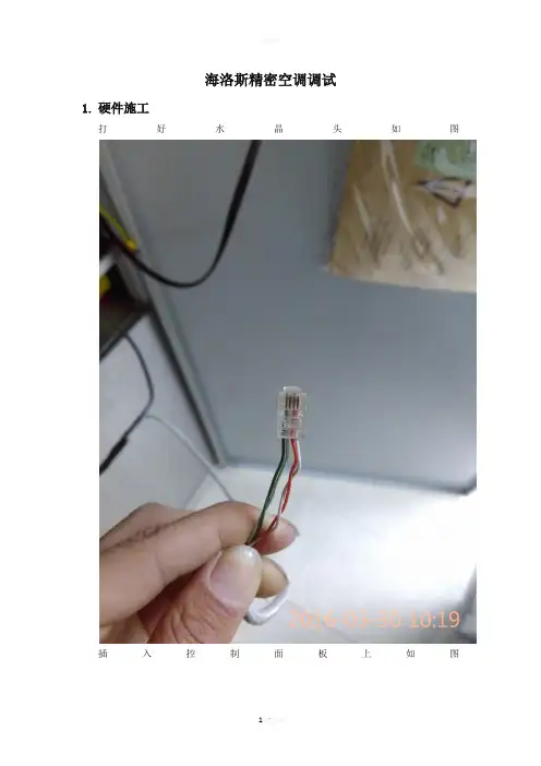
1.硬件施工
打好水晶头如图
插入控制面板上如图
再将网线的另一端接入通讯卡上如图
Comm2AC口接法是232交叉连接
将COMM1PC口用232连接方式接入C818上如图
这里说明一下如果空调到这个控制器连接成功了,那么COMM2AC的指示灯要亮绿灯,从空调到这个信号盒子这边过来的信
号是422信号,到盒子这边分别接4根线,485是不行的.请参考附件里关于这种空调的接线方式.
端子上没有明显的标示,做好问厂家端子的接口都代表什么意思!上图是厂家给错误接口,总是调不通,实在没有办法就一个一个接口试正确的如下图
在使用厂家的给软件测试如图
厂家软件只能确定接线联通,但是厂家说版本问题没有数据显示
再用公式的驱动如下图
得出的数据明显不对,到这个时候不要急着去问别人,自己试试其他的驱动脚本如下图
有了正确数据后基本数据就没有什么问题了
欢迎您的下载,
资料仅供参考!
致力为企业和个人提供合同协议,策划案计划书,学习资料等等
打造全网一站式需求。

HIROSS(一)恒温恒湿机房精密空调操作手册HIMOD系列北京****科技有限公司技术部01月01日目录第一章 HIMOD系列海洛斯空调概述1.1型号多1.2控制技术先进1.3制冷系统1.4送风系统1.5加湿系统1.6加热系统1.7其它第二章 HIMOD系列海洛斯空调型号含义第三章有关空调的一些资料3.1气流组织方式3.2盖板纽开启方式3.3空调重量3.4机组尺寸及维护空间第四章制冷循环管路示意图4.1风冷却(A型)4.2水冷却(W型)4.3双冷源(D型)4.4单系统(C型)4.5双系统(C型)第五章调速风机调速接线示意图第六章 MICROFACE概述6.1概述6.2Microface面板简介6.3LCD液晶显示屏介绍第七章 MICROFACE面板的操作第八章控制器的使用8.1控制器(HIROMATIC)概述8.2控制器的操作8.3菜单结构第九章日常维护及特殊维护9.1日常维护9.2特殊维护第十章常见及处理10.1低压10.2高压10.3加湿10.4失风10.5电加热过热10.6显示器发黑10.7空调不制冷附录 1:参数列表附录2:内容列表附录3:各菜单项含义第一章 HIMOD系列海洛斯空调概述HIMOD系列海洛斯空调(HIMOD空调)是当今世界上最先进的机房专用恒温恒湿机房专用精密空调。
随着IT业的突飞猛进的发展,各种布局、面积差别很大的机房如雨后春笋般纷纷出现了,使用环境也不一而同。
为适应各种不同要求的机房,新开发的海洛斯HIMOD系列空调应运而生。
她是在保留她的前一代产品HIRANGE系列机房空调的优点,又应用了当今世界上提高了的制冷技术及制冷部件制造工艺,使用当今最先进的模块化设计理念生产出来的高科技机房空调产品。
1.1型号多HIMOD空调有多种不同的型号,采用风冷却的A型,水冷却的W型,双冷源的H型和D型(机组即可以自身制冷又可以采用其他冷源),免制冷C型。
各种型号空调均有多种送风方式。

海洛斯操作维护指南E海洛斯(Helios)是一种用于控制和监测太阳能电池板数组的软件。
它能够设置太阳能电池板的运行模式,跟踪电池的性能,并提供错误报告和警报。
为了确保太阳能电池板组织的可靠运行,海洛斯操作维护指南E提供了以下几点建议。
1.遵守安全操作规程:在进行海洛斯操作之前,确保已经熟悉了所有的安全操作规程。
这包括穿戴适当的个人防护设备,并了解如何正确地使用和操作电力设备。
2.确保良好的清洁环境:海洛斯操作期间,要确保操作环境干净整洁。
避免灰尘、污垢和杂物的堆积,以防止设备的堵塞或损坏。
定期清洗太阳能电池板的表面,以确保最大的太阳能吸收效率。
3.定期检查设备的运行状况:定期检查太阳能电池板的运行状况,以确保其正常工作。
检查电池板的线路连接、绝缘情况和电压输出等,并确保无损害或异常现象。
4.及时处理错误和故障:一旦发现任何错误或故障,应立即采取措施进行修复。
不要忽视或延迟修复,以免造成更严重的问题。
及时修复能够最大程度地减少停机时间和性能损失。
5.定期备份和存储数据:海洛斯系统生成的数据对于太阳能电池板的性能分析至关重要。
为了确保数据的安全性和可用性,定期进行数据备份,并存储在安全可靠的位置。
6.软件更新和升级:随着技术的不断发展,海洛斯操作软件可能会有更新和改进的版本。
定期检查是否有新的软件更新,并在升级前备份数据。
升级软件可以提高系统的性能和功能,并解决可能的漏洞和问题。
7.培训和教育:了解海洛斯操作的基本知识和技能对于维护和操作太阳能电池板非常重要。
进行相关培训和教育,以便能够更好地理解和使用海洛斯系统,并有效地解决可能出现的问题。
8.备件和维修设备:为了应对突发的故障和问题,准备好所需的备件和维修设备非常重要。
这样可以避免因为等待备件或维修设备而导致的生产停顿和性能损失。

Hydronic Unit Heater Steam Rig HeaterThis manual covers installation, maintenance,repair, and replacement parts.Industrial GradeHeat-Exchanger Unit HeatersPart No. SRH2HUH2-NA-OM-APrinted in CanadaWARNING!Please adhere to all instructions published in this manual. Failure to do so may be dangerous and may void your warranty.The heat-exchanger core is not field repairable.Contact factory for a replacement core if fluid leakage occurs.^ NEMA motors are to be operated at ±10% of the nameplate voltage. If the motor is marked 208-230V the tolerance must be calculated from 230V. If the motor is marked 230V it is still suitable for 208V operation but the tolerance must be calculated from 230V. For 3-phase motors the line to line full load voltage must be balanced within 1%. †Thread-on fittings. Shipped loose and must be installed on site. C3 connection also includes C2 connection. ◊ Other voltages / frequencies available upon request. Longer lead times may apply. Contact factory* Standard Marathon NEMA ex-proof motor is suitable for Class I & II, Div. 1 & 2, Groups C, D, F & G; T3B.Heater Model Code & Option CodesModel CodingModel CodeOption CodesPhysical Dimensions (36 inch model)Model12"16"20"24"30"36"Fan Diameter inch (mm) 12 (304.8) 16 (406.4) 20 (508.0) 24 (609.6) 30 (762.0) 36 (914.4) Air Delivery* CFM (m 3/hr) 1090 (1852) 1650 (2803) 3000 (5097) 3800 (6456) 5500 (9344) 8350 (14186)Approx. Air Velocity* FPM (m/s) 1305 (6.6) 1111 (5.6) 1309 (6.6) 1138 (5.8) 1066 (5.4) 928 (4.7) Air Throw* @ 15 psi steam ft (m) 45 (13.7)65 (19.8)70 (21.3)80(24.4)85 (25.9)70 (21.3)Motor Power HP (Watts)1/4 (186) or 1/3 (248) 1/2 (373)1/2 (373) 3/4 (559)1 (746)Rec. Min. Mounting Height ft (m) 7.5 (2.3) 7.5 (2.3) 7.5 (2.3) 7.5 (2.3)7.5 (2.3)7.5 (2.3)Specifications By Model Size - North American Heaters - 60Hz* At 70°F (21°C), 60 Hz and sea level.Pressure Equipment Approvals SRH2: North America - CRN: 0H14931.2C - steam.HUH2: North America - CRN: 0H14933.2C - steam or fluids.Heater Core Maximum Pressure Rating SRH2 = 150 psig (1034 kPa). HUH2 = 400 psig (2758 kPa).Heater Core MaximumDesign Temp.550 °F (288°C).Heater Core Minimum DesignMetal Temp.-20°F (-29°C).Cabinet Material 14-gauge (0.075") (1.9 mm) steel. 36" model is 12-gauge (0.105") (2.7 mm) steel. Epoxy/polyester powder coated.Louver Blades Anodized extruded aluminum.Fan Spark-resistant aluminumFan Guard Split design with close wire spacing. A Ø3/8" (9.5 mm) probe will not enter.Motor Drive Thermally protected permanently lubricated ball bearing type. (36" model comes with maintenance free speed reducer).Mounting Holes 5/8"-11 UNC: 4 holes at top of heater (12" model has only 2 holes).Fluid Connections Standard: 2" NPT female inlet and outlet (configuration of fluid connection locations can be reversed by rotating the core). Other connection types are available (see model code chart).Header Material 12 gauge (0.105")(2.7 mm) and 3/16" (4.8 mm) carbon steel plate conforming to ASME requirements.Finned Tubes 5/8" (15.9 mm) outside diameter [16-gauge, 0.065" (1.6 mm) wall thickness] carbon steel tubes with 1-1/2" (38.1 mm) outside diameter copper-free, L-foot, tension-wound aluminum fins @ 10 fins per inch.General SpecificationsSRH2 Heaters 12" 16" 20" 24" 30" 36" Net Weight (no options) Lbs (kg) 88 (39.9) 106 (48.1) 149 (67.6) 210 (95.3) 257 (116.6) 482 (218.6) Shipping Weight (no options) Lbs (kg) 138 (62.6) 158 (71.7) 207 (93.9) 275 (124.7) 332 (150.6) 594 (269.4) with 2” NPT nipples (add) Lbs (kg) 1 (0.4) 1 (0.4) 1 (0.4) 1 (0.4) 1 (0.4) 1 (0.4) with flanges & nipples (add) Lbs (kg) 14 (6.3) 14 (6.3) 14 (6.3) 14 (6.3) 14 (6.3) 14 (6.3) HUH2 Heaters12" 16" 20" 24" 30" 36" Net Weight (no options) Lbs (kg) 88 (39.9) 106 (48.1) 149 (67.6) 210 (95.3) 264 (119.7) 491 (222.7) Shipping Weight (no options) Lbs (kg) 138 (62.6) 158 (71.7) 207 (93.9) 275 (124.7) 339 (153.7) 603 (273.5) with 2” NPT nipples (add) Lbs (kg) 1 (0.4) 1 (0.4) 1 (0.4) 1 (0.4) 1 (0.4) 1 (0.4) with flanges & nipples (add) Lbs (kg) 14 (6.3) 14 (6.3) 14 (6.3) 14 (6.3) 14 (6.3) 14 (6.3) Weights - North American Heaters12" 16" 20" 24" 30" 36"Front of Heater (dBA)3 feet 78 78 83 82 90 82 10 feet 71 73 76 76 83 76 15 feet 70 70 74 74 81 74Rear of Heater (dBA)3 feet 78 78 83 82 89 80 10 feet 71 72 77 75 83 76 15 feet 70 71 75 74 81 74ModelNoise Data By Model Size - North American Heaters - 60HzConditions For Safe Use1. Remove any dirt / dust from heater cabinet using a damp cloth to mitigate electrostatic charge buildup.2. Do not install the heater in an environment which could potentially cause an electrostatic charge buildup on the cabinet (i.e. exposure to high pressure steam).3. The heater core is NOT field repairable. All defective cores must be replaced with a factory suppliedunit.4. The motor is NOT field repairable. All defective motors must be replaced with a factory supplied orfactory approved unit.5. Flameproof joints are NOT field repairable. Any damaged enclosures/fittings will have to be replacedwith factory approved units.6. For any field repairs use only original factory installed fasteners or factory supplied replacementfasteners.— INSTALLATION —These instructions are to be used as a general guideline only.LocationPlease follow guidelines below for optimum heating results:1. Do not install heaters such that airflow is blocked or impeded by equipment or walls.2. For occupant comfort, position heaters so that air discharge is directed across areas of highest heat loss,such as doors, windows, and outside walls.3. For large areas, arrange heaters such that the air discharge of one heater is directed towards the inlet of thenext heater. This sets up a rotational airflow with air circulation in the central area of the building.4. For equipment freeze protection, direct air discharge at required equipment.5. For large workshops or warehouses it may be acceptable to use fewer, but larger heaters.6. Do not direct air discharge towards a room thermostat.7. Heater inlet and outlet coupling connection locations can be reversed in the field by removing the core,rotating it 180 degrees, and then re-installing it. Cabinet plugs can then be repositioned.Mounting1. A variety of mounting brackets are available from the factory to aid in installation.2. The heater is designed to be installed in an upright and level position. While it may be installed in otherpositions, for steam service, the inlet must be above the outlet and the bottom of the heat exchanger must drain towards the outlet.3. Heaters are designed to be suspended from the top of the cabinet using either two or four 5/8"–11 UNCbolts or threaded rod.4. It is essential that adequate structural support be provided for installation. The mounting structure must bestrong enough to support the heaters weight, provide sufficient stiffness to prevent excessive vibration, and withstand all probable abusive situations such as transportable installations where truck off-loading impacts, etc. may occur.Mounting Heights and Clearances1. To ensure that warm air reaches the floor, heaters are usually mounted 7-1/2 ft. (2.3m) to 12 ft. (3.6 m)above the floor. Heaters may be mounted at higher elevations and still provide warm air at floor level however, the maximum mounting elevation at which this occurs depends on location and operational conditions.2. Louvers may be adjusted to provide greater downward deflection of the discharge air. However, it isrecommended that louvers not be set <15° from the closed position.Fan Clearance1. Verify the minimum required clearance between fan blades / fan shroud and the fan blades / fan guard priorto heater power up.Heater Size 12" 16" 20" 24" 30" 36"Min Clearance 2.0 mm 2.0 mm 2.5 mm 3.0 mm 3.8 mm 4.6 mm— Piping Practices —1. Steam unit heaters condense steam rapidly, especially during warm-up periods. The return piping must beplanned to keep the heat-exchanger’s core free of condensate during periods of maximum heat output, and steam piping must be able to carry a full supply of steam to the unit heater to take the place of condensed steam. Adequate pipe size is especially important when a unit heater fan is operated under on-off control because the condensate rate fluctuates rapidly.2. Heater is to be connected and serviced only by qualified personnel. For additional piping information referto local codes.3. Eliminate pipe stress by adequately supporting all piping. Do not rely on heater to support piping.4. Take off all branch lines from the top of steam mains, preferably at a 45° angle, although vertical 90°connections are acceptable.5. Pipe the branch supply line into the steam unit heater’s inlet at the top and the return branch line from theoutlet at the bottom. The heater’s inlet and outlet coupling connections can be reversed in the field by rotating the heat-exchanger core. Refer to Page 10, Heat-Exchanger Core AssemblyReplacement.6. In steam systems, the branch from the supply main to the heater must pitch down towards the main and beconnected to its top in order to prevent condensate in the main from draining through the heater. In long branch lines, a drip trap may be needed.7. Allow for pipe expansion to prevent excessive strain on the unit heater’s heat-exchanger core.8. The return piping from steam unit heaters should provide a minimum drop of 10" (254 mm) below theheater so that the pressure of water required to overcome resistances of check valves, traps, and strainers will not cause condensate to remain in the heater.9. In steam systems, where horizontal piping must be reduced in size, use eccentric reducers that permit thecontinuance of uniform pitch along the bottom of piping (in downward pitched systems). Avoid using concentric reducers on horizontal piping, because they can cause water hammer.10. Installing dirt pockets at the outlet of unit heaters and strainers with 0.063 in. (2 mm) perforations to preventrapid plugging are essential to trap dirt and scale that might affect the operation of check valves and traps.Strainers should always be installed in the steam supply line if the heater is valve controlled.11. In steam or hot water systems, rapid air removal is required because entrained air is a cause of corrosion.Hot water systems should be equipped with suitable air vent valves for rapid and complete air removal at high points, at the top of each unit heater, and ends of both supply and return mains. Proper air venting for steam systems can be achieved by use of a steam trap with an internal air vent.12. Steam traps must be located below the outlet of the unit heater. Consult the trap manufacturer for specificrecommendations. Each steam unit heater should be provided with a trap of sufficient size and capacity to pass a minimum of twice the normal amount of condensation released by the unit at the minimumdifferential pressure in the system. Trap capacity is based on the pressure differential between supply and return mains. Steam systems should be equipped with a float and thermostatic trap or inverted bucket trap with an air bypass.13. If the condensate return line is above the heater outlet or is pressurized, install a check valve after thesteam trap and a drain valve at the strainer to drain the system during the off season.14. Install pipe unions and shut-off valves at connection points of each unit heater to allow maintenance orreplacement of unit without shutting down and draining the entire system. For hot water systems include a balancing valve in return line for flow regulation. A drain valve should be provided below each unit heater to allow removal of water from the heat-exchanger core if located in an area subject to freezing.15. Adequate air venting is required for low-pressure closed gravity systems. The vertical pipe connection tothe air vent should be at least 3/4" NPT to allow water to separate from the air passing to the vent. If thermostatic instead of float-and-thermostatic traps are used in vacuum systems, a cooling leg must be installed ahead of the trap.16. In high-pressure systems, it is customary to continuously vent the air through a petcock unless the steamtrap has a provision for venting air. Most high-pressure return mains terminate in flash tanks that are vented to the atmosphere. When possible, pressure reducing valves should be installed to permit operation of the heaters at low pressure. Steam traps must be suitable for the operating pressure encountered.17. On steam systems where the steam supply to the unit heater is modulated or controlled by a motorizedvalve, a vacuum breaker should be installed between the unit outlet and a float and thermostatic trap.Heat-Exchanger Core Assembly Replacement1. Heat-exchanger core assemblies are heavy and replacement requires two people for safety reasons.2. It is not necessary to dismount unit heater from its support structures to remove the heat-exchanger core assembly. However, it may be advisable in some instances to allow for core assembly removal at ground or bench level.3. Remove the bottom heater cabinet cover which is attached with 6 screws and 3 bolts.4. Support the heat exchanger core assembly, then remove the 4 core bolts on each side of the cabinet (36" models have 6 core bolts).5. Lower the core assembly from heater.6. Reverse the procedure to install replacement core and tighten 4 core bolts to 90 in-lbs (10 N-m) torque, bottom panel screws to 28 in-lbs (3 N-m) , and fan panel bolts to 100 in-lbs (11 N-m) . (36" models have 6 core bolts)Fan, Fan Guard or Motor Replacement1. For replacement of fan or fan guard remove the 4 bolts holding motor to the motor mount. For 36" modelsalso remove speed reducer bolts. If replacing motor only on 36" models, only remove motor mounting bolts and C-face flange bolts.2. Detach two-piece fan guard assembly by removing top and bottom screws that attach the fan guard to thecabinet.3. Remove fan guard pieces through top or bottom. Due to stiffness of fan guards, you may need to removeouter two top or bottom bolts that attach the fan panel to the top or bottom cabinet panels to provide sufficient clearance.4. Lift the motor, (and speed reducer for the 36" model) and fan assembly off the motor mount.5. Loosen fan hub screw and remove fan blade from motor shaft.6. To reassemble, position fan on motor shaft with end of shaft even with face of hub. Ensure the set screw isfacing towards motor and lined up perpendicular to factory-ground flat on motor shaft. This flat is our “Easy-Off” fan blade replacement feature and only comes on motors purchased from Hazloc Heaters. Tighten set screw to 150 in-lbs (17 N-m) torque.7. Place motor, (and speed reducer for the 36" model) and fan assembly onto motor mount and fasten the two-piece fan guards to the cabinet.8. Center fan in the fan-shroud opening. The gap between the fan blades and fan shroud should be even forall fan blades. Ensure the minimum gap is maintained for all blades. See page 6 for minimum gap values. 9. Bolt motor (and speed reducer for the 36" model) to motor mount, tighten nuts to 250 in-lbs (28 N-m)torque. Manually spin the fan blade to ensure it rotates freely before reconnecting heater to power supply. Fan must rotate counterclockwise when viewed from rear of heater.— Repair and Replacement —Item (in-lbs)Fan blade set screw 1505/16 - 18 UNC motor nuts 250 1/4 - 20 UNC core bolts90 Torque Settings1/4 - 20 UNC fan panel bolts 100 5/16 - 18 UNC motor mount bolts 250 #10 - 24 UNC bottom panel & louver blade screws281/4 - 20 UNC fan guard self tapping screws 100 (N-m) 17 28 28 11 11 10 3Note: Heater inlet and outlet coupling connection locations can be reversed in the field by removing the core, rotating it 180 degrees,and then re-installing it. Cabinet plugs can then be repositioned.Item No.Description12 inch16 inch20 inch24 inch30 inchPart NumberPart NumberPart NumberPart NumberPart Number*** Please have heater model & serial number available before calling ***1 Core Kit Contact factory with heater model, size, number of passes and connection typePart #’s 1119 thru 11392 Louver Blade kit 1145 1146 1147 1148 11493 Motor Mount Kit 1151 1152 1153 1154 1155 4 Fan Guard Kit 1157 1158 1159 1160 1161 5 Fan - 5/8 inch hub 116311651167116911716 Motor Kit - 5/8 inch shaft Specify motor voltage, phase, frequency, horsepower and type of enclosure (general purpose or explosion-proof)7 Thread-on 2 inch NPT Nipple1176 8Thread-on 300# Raised Face Flange1177Note: Inlet and outlet couplingconnection locations can be reversed in the field by rotating the core.*All replacement part kits include fasteners12 inch to 30 inch models12 inch to 30 inch modelsItem No.Description36 inchPart Number*** Please have heater model & serial number available before calling ***1Core Kit Contact factory with heater model, size, number of passes and connection typePart #’s 1141 thru 11442Louver Blade Kit 11503 Motor Mount Kit 11564 Fan Guard Kit 1162 5Fan - 5/8 inch hub 11736 Motor Kit - 5/8 inch shaft Specify motor voltage, phase, frequency, horsepower and type of enclosure (general purpose or explosion-proof)7Thread-on 2 inch NPT Nipple 11768 Thread-on 300# Raised Face Flange1177 9Speed Reducer Kit1178Note: Inlet and outlet couplingconnection locations can be reversed in the field by rotating the core .*All replacement part kits include fasteners36 inch model36 inch modelRegular inspection, based on a schedule determined by the amount of dirt in the atmosphere, assures maximum operating economy and heating capacity.Annual Inspection (before each heating season)1. Check all terminal connections, electrical conductors, glands and cables for damage, looseness, defects,fraying, etc. and replace or tighten where applicable.2. Check for fluid leakage from heat-exchanger core. If fluid leakage occurs, remove heater from service andhave the heat-exchanger core replaced by a factory replacement unit. Refer to “Repair and Replacement” section for complete details. Note: This heat-exchanger core is not field repairable.3. Check electrical junction box. Inside of enclosure must be clean, dry, and free from any foreign materials.The cover must also be completely on and tight.4. Check motor shaft bearing play. Replace motor if play is excessive or if motor does not run quietly andsmoothly. Motor bearings are permanently lubricated.5. On 36" models, speed reducer is maintenance free. Check for excessive noise and vibration.6. Check fan. Replace immediately if cracked or damaged. Check the gap between the fan and fan shroudmeets the minimum spacing requirement.7. Check louvers. Louver screws should be tight. Louvers are not to be set <15° of the closed position.8. Check the tightness of all hardware. All nuts and bolts, including mounting hardware, must be tightened totorque settings on Page 10.9. Turn heater motor on for a minimum of 10 minutes. Check for air exiting heater through louvers and smoothrunning of the motor and fan assembly.Periodic Maintenance (before and as required during heating season) 1. Clean the following (remove dust using compressed air):∙ Finned tubes ∙ Fan∙ Fan Shroud ∙ Fan Guard ∙ Motor ∙ Louvers ∙ Cabinet 2. Check the following:∙ Motor / fan assembly (and speed reducer on 36" models) for smooth and quiet operation. ∙ Louvers for proper angle and tightness. ∙ Electrical junction box covers are secure.∙Gap between the fan blade / fan shroud and the fan blade / fan guard meet the minimum spac-ing requirement (see page 6 for minimum values).— Maintenance Program —Date of Maintenance PerformedByMaintenance PerformedDate of Maintenance PerformedByMaintenance PerformedPRINTED IN CANADA ©Copyright 2018The information contained in this manual has been carefully checked and verified for accuracy. Specifica-tions subject to change withoutnotice.Hazloc Heaters is a trademark ofHazloc Heaters Inc.#1, 666 Goddard Ave. NE Calgary, Alberta T2K 5X3 CanadaTel.: +1-403-730-2488 Fax: +1-403-730-2482Customer Toll Free (U.S. & Canada): +1-866-701-Heat (4328) Limited 18-Month WarrantyHazloc Heaters TM warrants all SRH2 & HUH2 series of heat-exchanger unit heaters against defects in materials and workmanship under normal conditions of use for a period of eighteen (18) months from date of pur-chase based on the following terms:1. The heater must not be modified in any way.2. The heater must be stored, installed and used only in accordance with the owner’s manual and attached data plate information.3. Replacement parts will be provided free of charge as necessary to restore any unit to normal operating condition, provided that the defective parts be returned to us freight prepaid and that the replacement parts be accepted freight collect.4. The complete heater may be returned to our manufacturing plant for repair or replacement (at our discretion), freight charges prepaid.5. Components damaged by contamination from dirt, dust, etc. or corrosion will not be considered as defects.6. This warranty shall be limited to the actual equipment involved and, under no circumstances, shall include or extend to installation or removal costs, or to consequential damages or losses.。

HIROSS恒温恒湿机房精密空调操作手册HIMOD系列北京****科技有限公司技术部2009年01月01日目录第一章HIMOD系列海洛斯空调概述型号多控制技术先进制冷系统送风系统加湿系统加热系统其它第二章HIMOD系列海洛斯空调型号含义第三章有关空调的一些资料气流组织方式盖板纽开启方式空调重量机组尺寸及维护空间第四章制冷循环管路示意图风冷却(A型)水冷却(W型)双冷源(D型)单系统(C型)双系统(C型)第五章调速风机调速接线示意图第六章MICROFACE概述概述面板简介液晶显示屏介绍第七章MICROFACE面板的操作第八章控制器的使用控制器(HIROMATIC)概述控制器的操作菜单结构第九章日常维护及特殊维护日常维护特殊维护第十章常见报警及处理低压报警高压报警加湿报警失风报警电加热过热报警显示器发黑空调不制冷附录1:参数列表附录2:报警内容列表附录3:各菜单项含义第一章HIMOD系列海洛斯空调概述HIMOD系列海洛斯空调(HIMOD空调)是当今世界上最先进的机房专用恒温恒湿机房专用精密空调。
随着IT业的突飞猛进的发展,各种布局、面积差别很大的机房如雨后春笋般纷纷出现了,使用环境也不一而同。
为适应各种不同要求的机房,新开发的海洛斯HIMOD系列空调应运而生。
她是在保留她的前一代产品HIRANGE 系列机房空调的优点,又应用了当今世界上提高了的制冷技术及制冷部件制造工艺,使用当今最先进的模块化设计理念生产出来的高科技机房空调产品。
型号多HIMOD空调有多种不同的型号,采用风冷却的A型,水冷却的W型,双冷源的H型和D型(机组即可以自身制冷又可以采用其他冷源),免制冷C型。
各种型号空调均有多种送风方式。
控制技术先进她仍旧沿用HIRANGE系列空调前台控制的优点,因为采用前台控制用户在使用时不必要直接接触与强电相关的电器设备,因而极为安全。
同时也仍采用HIROMATIC图形控制器,这使得对空调的操作依然简单直观易懂,方便用户的使用与维护。

Waters 600高精度四元梯度泵中文操作说明书 Waters 600E 控制器前面板Waters 600E 泵液晶显示屏方向键亮度调整键电源开关相对屏幕功能键操作功能键数字键确认键梯度控制器画面一. 操作功能画面说明1.Set up --- 设定泵硬件系统配置选择A,B,C,D 溶剂瓶的氦气法脱气装置开关, 0=关,1=开设定色谱柱加热装置温度上限泵硬件系统配置键压力上下限控制键盘锁定键帮助键2. Direct --- 等度(Isocratic)操作设定FLOW RATE :流动相流速设定( 范围随着硬件规格而定)。
COMPOSITION :流动相设置比例(A+B+C+D=100%)。
CURRENT :当前状态流动相比例。
NEW :改变流动相比例。
SPARGE:氦气脱气装置流量(0~100)。
TEMPERATURE:设定柱温箱温度(室温~9 0℃)。
PRESSURE:显示系统压力值。
SWITCH:外接装置的控制开关。
STOP FLOW:停止泵流速。
3. Operate Method --- 执行梯度功能(GRADIENT)操作设定执行梯度方法代号(#1~15)4. Program Method --- 编辑梯度表(Gradient Table)显示或变更表号清除一行清除表格全部内容存储键5. Program Table --- 编辑事件表(Event Table)显示或变更表号清除一行清除表格全部内容存储键二. 基本操作说明(等度 ISOCRATIC)1. 打开氦气钢瓶,设定输出压力为50~90psi(使用在线脱气机者,请忽略此步骤)。
2. 将溶剂输送塑料管置入储液瓶内流动相中(请注意输送塑料管的代号),打开电源开关至ON(1)的位置,出现如下的开机画面:3. 按一下“Set Up” 功能键,即进入泵设定(Pump Setup )画面。
4. 移动光标设定欲使用的溶剂瓶A,B,C 或D 的氦气法脱气装置开关,使其为“ENABLE” (按“1”, Enter ⇒ ENABLE 打开;按“0”,Enter ⇒ DISABLE 关闭)5. 如果使用柱温箱,设定温度数值(温度上限应低于溶剂沸点)。

HIROSS恒温恒湿机房精密空调操作手册北京海洛斯机房设备工程有限责任公司技术部目录第一章概述----------------------------------------------------------------11.1空调型号---------------------------------------------------------11.2空调重量---------------------------------------------------------21.3机组尺寸及维护空间------------------------------------------31.4电气数据---------------------------------------------------------3 第二章MICROFACE操作-----------------------------------------------52.1概述----------------------------------------------------------------52.2 Microface接口面板简介--------------------------------------72.3 LCD液晶显示屏介绍-----------------------------------------72.4 MICROFACE面板的操作---------------------------------8 第三章控制器的使用----------------------------------------------------103.1控制器(HIROMATIC)概述-----------------------------103.2控制器(HIROMATIC)操作------------------------------------11 第四章日常维护及特殊维护-------------------------------------------294.1日常维护--------------------------------------------------------294.2特殊维护--------------------------------------------------------31 第五章常见报警及处理-------------------------------------------------325.1报警/故障检查流程-------------------------------------------325.2常见报警故障处理方法--------------------------------------36HIMOD空调操作手册附表1:报警内容列表------------------------------------------------------40 附表2:参数列表(旧版本)---------------------------------------------43附表3:参数列表(新版本)---------------------------------------------49第3页共60页第一章概述HIMOD系列海洛斯空调(HIMOD空调)是当今世界上最先进的恒温恒湿机房专用精密空调。
waters操作手册英文版Waters Operation ManualIntroductionThis manual is designed to provide detailed instructions and guidance for operating Waters equipment It is important to follow these instructions carefully to ensure accurate and efficient operationSafety PrecautionsBefore starting any operation, it is crucial to be aware of the safety precautions:1、 Always wear appropriate personal protective equipment (PPE),such as safety glasses and gloves2、 Ensure the working environment is wellventilated3、 Do not operate the equipment if you are not familiar with its functions or if it shows any signs of damageEquipment OverviewThe Waters system typically consists of several components, including the chromatographic column, detector, pump, and control unit Each component has its specific role and functionsThe chromatographic column is responsible for separating the components of the sample The detector measures the signal generated by theseparated components The pump controls the flow rate of the mobile phase, and the control unit allows for programming and monitoring of the entire processStartup Procedure1、 Power on the Waters equipment and allow it to initialize2、 Check the connections of all components to ensure they are secure3、 Set the appropriate parameters in the control unit, such as flow rate, wavelength for the detector, and run timeSample Preparation1、 Prepare the sample according to the specific requirements of the analysis2、 Filter the sample to remove any particulate matter that could clog the systemInjection of Sample1、 Use a precise syringe to inject the sample into the injection port2、 Ensure the injection volume is within the specified rangeMonitoring the RunDuring the chromatographic run, monitor the signals from the detector on the display of the control unit Keep an eye on any abnormal peaks or fluctuations that could indicate a problemData AnalysisAfter the run is completed, the collected data can be analyzed using the software provided with the Waters system This may include peak identification, integration, and calculation of concentrationsMaintenance and TroubleshootingRegular maintenance is essential to keep the Waters equipment in optimal condition This includes cleaning the chromatographic column, checking the pump seals, and calibrating the detectorIf you encounter any problems during operation, refer to the troubleshooting section of this manual Common issues such as pressure fluctuations, baseline noise, or no signal may have specific solutions listedShutdown Procedure1、 At the end of the operation, stop the pump first2、 Turn off the detector and the control unit3、 Disconnect the power supplyIt is important to note that the specific procedures and parameters may vary depending on the model and configuration of your Waters equipment Always refer to the manufacturer's documentation for detailed and accurate informationWe hope this manual provides you with a clear understanding of operating the Waters equipment If you have any further questions or need additional support, please contact the manufacturer's customer serviceRemember, proper operation and maintenance will ensure the longevity and accuracy of your Waters system for reliable analytical results。

Himod机房专用空调操作维护指南捷联发展CHAT UNION DEVELOPMENT LTD北京经济技术开发区荣昌东街7-105TEL: 010-******** FAX: 010-********前 言感谢您选择了意大利“海洛斯”机房专用空调。
意大利海洛斯公司,于1965年着手研制开发适用于机房,精密环境控制的专用空调机,目前已成为欧洲最大的机房专用空调生产厂。
也是世界上机房专用空调行业最先进的科研中心。
该专用空调采用先进的模块化设计。
具有高效节能、经济耐用、数字控制、适应性强、维修方便和环境保护等特点。
特别适应于计算机房、网络中心、交换机房、医院、博物馆等要求极高的环境中使用。
并得到广泛好评。
为了使您使用好该专用空调设备,请您仔细阅读该“操作维护指南”。
北京捷联设备有限公司工程部目 录1. 安装前的工作步骤....................................................2. 主板介绍与操作说明..................................................2.1 microface板简介..................................................2.2 microface 说明与连接.............................................2.3 LCD显示屏和microface网络......................................2.4 microface程序...................................................2.5 HIROBUS 连接..................................................3. HIROMATIC控制器.................................................3.1 Hiromatic(普通型)描述与连接......................................3.1.1 前面板功能描述.............................................3.1.2 如何进入HIROMATIC菜单..................................3.1.3 设定点菜单.................................................3.1.4 系统信息窗口...............................................3.1.5 图表数据记录...............................................3.1.6 状态报告...................................................3.1.7 HIROMATIC PCB 板上的桥.................................3.1.8 参数与菜单描述.............................................3.1.9 接口报警/警告一览表.......................................3.2 Hiromatic G/E...................................................3.3 兼容性解释.......................................................3.4 Hiromatic 参数单.................................................3.5 Hiromatic 信息/警告/报警.......................................4. 随机控制器..........................................................4.1 液晶显示屏(LCD).................................................4.2 液晶显示器的参数.................................................4.3 微电脑控制器电子液晶显示屏警告/报警............................5. 常见报警及处理......................................................6. 日常检测与维护......................................................1 7 7 7 9 10 10 11 11 13 14 14 14 14 15 15 16 24 25 47 49 60 62 62 65 79 80 82标准管路直径(有效的相当长度可达30mm)R407C 18Ø122Ø116Ø122Ø122Ø128Ø128Ø1R2222Ø122Ø118Ø122Ø128Ø128Ø135Ø1气管外径X 厚度(mm)液管外径X 厚度(mm)R2218Ø118Ø118Ø118Ø122Ø122Ø128Ø1R407C 16Ø118Ø114Ø118Ø118Ø122Ø128Ø1Tab.4-管路直径 远端冷凝器20/4224/4626/3228/5534/6540/8199型号输入动力线线径型号 XX U/O 40、42、46、55、6534-242081 99线径25161035给排水管径上水排水4"1-1’/2’2.1Microface板简介3.1.1前面板功能描述所有操作可在Hiromatic面板上进行,如下所示:3.1.2如何进入HIROMATIC菜单3.1.3设定点菜单3.1.4系统信息窗口3.1.5图表数据记录3.1.6 状态报告3.1.8参数与菜单描述3.1.93.1.9接口报警/警告一览表3.1.9 接前往主窗口或回到上一个窗口按下该按钮可以启动/关闭系统和机组(如果启用)报警和警告清除如果一个(或多个)报警被激活或者没有清除,则红色灯将点亮当机组工作时,绿色灯将点亮当机组通电时,橙色灯将点亮3.2 Hiromatic G/E(改进型)3.2.1 Hiromatic G 的面板设计用于HPAC 机组的Hiromatic G 的面板包含一个背投图例式液晶显示屏、9个允许输入功能的按钮以及三个灯(LED)(参见图30)。

HIROSS恒温恒湿机房精密空调操作手册HIMOD系列北京****科技有限公司技术部2009年01月01日目录第一章HIMOD系列海洛斯空调概述 (4)1.1型号多 (5)1.2控制技术先进 (5)1.3制冷系统 (5)1.4送风系统 (6)1.5加湿系统 (6)1.6加热系统 (6)1.7其它 (7)第二章HIMOD系列海洛斯空调型号含义 (7)第三章有关空调的一些资料 (9)3.1气流组织方式(详见下图) (9)3.2盖板纽开启方式(详见下图) (9)3.3空调重量(单位:Kg) (10)3.4机组尺寸及维护空间 (10)第四章制冷循环管路示意图 (11)4.1风冷却(A型) (11)4.2水冷却(W型) (12)4.3双冷源(D型) (13)4.4单系统(C型) (14)4.5双系统(C型) (14)第五章调速风机调速接线示意图 (15)第六章MICROFACE概述 (17)6.1概述 (17)6.2Microface面板简介液晶显示屏 (17)6.3LCD液晶显示屏介绍 (17)第七章MICROFACE面板的操作 (18)第八章控制器的使用 (19)8.1控制器(HIROMATIC)概述 (19)8.2控制器的操作 (19)8.3菜单结构 (24)第九章日常维护及特殊维护 (26)9.1日常维护 (26)9.2特殊维护 (29)第十章常见报警及处理 (30)10.1低压报警 (30)10.2高压报警 (31)10.3加湿报警 (32)10.4失风报警 (33)10.5电加热过热报警 (33)10.6显示器发黑 (33)10.7空调不制冷 (33)附录1:参数列表 (34)附录2:报警内容列表 (46)附录3:各菜单项含义: (53)第一章HIMOD系列海洛斯空调概述HIMOD系列海洛斯空调(HIMOD空调)是当今世界上最先进的机房专用恒温恒湿机房专用精密空调。
随着IT业的突飞猛进的发展,各种布局、面积差别很大的机房如雨后春笋般纷纷出现了,使用环境也不一而同。

OPERATOR’S MANUAL MASSIMOZLST13150 Snow BlowerIMPORTANTREAD INSTRUCTIONS CAREFULLY BEFORE OPERATIONImportant Safety Operation Practices1WARNING: This symbol points out important safety instructions which, if not followed, could endanger the personal safety and/or property of yourself and others. Read and follow a llinstructions in this manual before attempting to operate this machine. Failure to comply withthese instructions may result in personal injury.When you see this symbol, HEED ITS WARNING!DANGER: This machine was built to be operated according to the safe operation practices inthis manual. As with any type of power equipment, carelessness or error on the part of theoperator can result in serious injury. This machine is capable of amputating hands and feet and throwing objects. Failure to observe the following safety instructions could result in s e r i o u sinjury or death.General Operation1.Carefully read in their entirety the vehicle’s operator’smanuals and this equipment’s operator’s manuals beforeattempting to assemble or operate the equipment.Keep both manuals in a safe place for future and regularreference and for ordering replacement pa rt s.2.The vehicle is designed for off-road usage and should notbe operated on public highways. Know and comply withall laws and regulations governing the use of off-highwayvehicles in your area.3.The vehicle handles and maneuvers differently thana normal passenger car. Sharp high speed turns andabrupt maneuvers can cause vehicle to roll over or go outof control. Slow down when turning and avoid abruptmaneuvers.4.Be familiar with all instructions and controls and theirproper operation before starting the vehicle.5.Do not allow children to operate vehicle. Do not allowadults to operate it without proper instruction. Onlypersons well acquainted with these rules of safeoperation s h o u l d be allowed to use the equipment.6.Watch for traffic when operating near or crossing roadways.This vehicle is not intended for use on any public r oadway.7.No one should operate this equipment while intoxicatedor while taking medication which impairs the senses orreactions.8.Never carry more than one passenger. This vehicle isdesigned to carry the driver and one passenger only.No riders are allowed in cargo box or anywhere else onvehicle.9.Keep all body parts (i.e. head, arms, hands, legs, feet) insidevehicle when vehicle is in motion.10.Always remain seated and keep both hands on the steeringwheel when driving the vehicle.11.12.13.14.15.16.17.18.19.20.21.Sit on the center of the seat and keep both feet withinthe foot platform perimeter. The foot platform maybecome slippery from snow or ice, use extra caution when mounting or dismounting the vehicle.Inspect area around vehicle before moving, especially inreverse. Back up slowly. Always look down and behindbefore and while backing to avoid a back-over accident.Keep bystanders out of area.Do not mount or leave vehicle while it is in motion or inactual operation.Never leave vehicle unattended with the key in theignition. Always turn key to the “Stop” position, set theparking brake and remove key.Check overhead clearances carefully before driving underlow hanging tree branches, wires, etc.,or in any othersituation where the operator or passenger may be struckor pulled from the unit. Such negligence could result inserious injury.Engine must be stopped when cleaning, servicing,adjusting, repairing, or installing attachments on utilityvehicle.The vehicle and attachment should be stopped andinspected for damage after striking a foreign object.The damage should be repaired before restarting andoperating the equipment.Do not start and run vehicle in an inside area, unless it isadequately ventilated. Engine exhaust contains carbonmonoxide fumes, which are very poisonous and can bedeadly.Always inspect the vehicle each time you use it to makesure it is in safe operating condition.Operate blade only in daylight or in good artificial light.Always use vehicle lights while operating in low lightsituations.Avoid overturns—Do not clear snow across the face ofslopes. Exercise extreme caution when changing direction on slopes. Do not attempt to clear steep slopes.222.No one should be allowed near the working area when t heblade is being operated.23.Do not overload the vehicle capacity by attempting toclear snow at too fast of a rate. Take the time to do thejob in a safe manner.24.Be careful to avoid catching the blade on stumps orother i mmovable objects.25.Never use the blade to tow another object.e extreme care when operating close to ditches,fences o r on hillsides.27.Be sure that the blade is fully raised and is in thestraight f orward position when in transport.28.When turning close to buildings or passing throughnarrow a reas, be sure to allow sufficient clearance forthe blade.29.If situations occur which are not covered in thismanual u se care and good judgement. Contact yourlocal Massimo dealer, or call toll free 1-877- 881-6376for assistance.Slope OperationSlopes are a major factor related to loss of control and rollover accidents, which can result in severe injury or death. If a slope i s steeper than a 15° incline, do not operate this unit on that area. Exercise extreme caution while operating on slopes.Do:1.Travel straight up and down slopes, not across.2.Exercise extreme caution when changing direction onslopes.3.Travel slowly while on a slope. Always keep the forwardspeed limited when going down slopes.4.Keep all movement on the slopes slow and gradual. Avoidstarting or stopping on a s lope.Do Not:1.Do not travel near drop-offs, ditches or embankments. Thevehicle could suddenly turn over if a wheel is over the edgeof a cliff, ditch or if an edge caves in with the weight of theunit.2.Do not stop or start suddenly when going uphill or downhill.Be especially cautious when changing direction on slopes.3.Do not turn sideways to the hill. The vehicle may roll over. Ifyou must turn, go slow and do so carefully and gradually. ChildrenTragic accidents can occur if the operator is not alert t othe presence of children. Children are often attracted tothe vehicle. They do not understand the dangers. Never assume that children will remain where you last sawthem. A void run over accidents.a.Keep children out of the immediate area of thevehicle and in watchful care of a responsibleadult o ther than the operator.b.Be alert and turn the vehicle off if a child entersthe area.c.Before and while reversing, look behind and downfor small children.d.Never carry small children, they may fall off andbe seriously injured or interfere with safevehicle o peration.e extreme care while approaching blindcorners, d oorways, shrubs, trees or other objectsthat may block your vision of a child who may runinto the path of the vehicle.f.Remove key when vehicle is unattended toprevent u nauthorized operation. Never allowchildren under 16 years old to operate this vehicle.g.Children 16 years old and over should read andunderstand the operation instructions and safetyrules for the vehicle and equipment, and should betrained and supervised by an adult.h.Do not let children ride in the cargo box, in thedriver’s or passenger’s lap or anywhere other thanthe passenger seat. Never give small children aride; not even in the passenger seat. They may falloff.3e e e e e a e e ea e a a e a a a a a e a eInstallingthe SnowplowI MPORTA NT: Refer to your Massimo Owner’s Manualfor any information relating to the use of your 4x4 unit.These instructions are for assembly of your new acces-sory to further enhance your UTV experience.Installing the Snow BlowerInstalling the Mounting HardwareInstall the snow plow mounting brackets1. Mount the snow plow mounting brackets on the chassis,as shown in figure 2-1. Use four U boltsand the 3/8 locking nuts in the provided holes. See Fig. 2-1/2-2.2. Securely tighten the 3/8”bolts to 25ft. lbs.Install the Snow Tube:1. Install the snow chute on the big cover, as shown in figure 2-3. Use four screws,six M6×16 bolts and eight M6 locking nuts. See Fig. 2-32. Securely tighten the M6×16 bolts to 6-9ft. lbs.IM PORTA NT Refer to your Massimo Owner’s Manual for any information relating to the use of your UTV unit. These instructions are for assembly of your new accessory to further enhance y ourUTV experience. Specifications subject to change without notice or obligation.Install the Gasoline Engine Cover:1. Remove the supporting frame 1, 2 and 3 fromthe gasoline engine cover, as shown in figure2-4.2. Use five M5×16 bolts and put it on the plainwashers, then fix the gasoline engine cover onthe three supporting frames. Do not tighten.3. Mount the three supporting frames to thecorresponding holes on the gasoline engine andadjust the location of the gasoline engine cover.Then, tighten each bolt. Securely tighten theflange bolts on the gasoline engine to 10-12ft.Lbs. Securely tighten the hexagon bolts on thegasoline engine cover to 4-6ft. lbs.Figure 2-34Figure 2-2Figure 2-4Supportingframe3Supportingframe 1Supportingframe 2Figure 2-14Figure 2-5Figure 2-6 Install the Connecting Frame :1. Insert the three-hole end of the connecting frame into the corresponding location of the snow blower. See figure 2-5.2. Use two M12×70 hexagon bolts and two locknuts to tighten the holes.Tip : You can select two of the three holes on the connecting frame to adjust the distance between the snow blower.Connect the snow blower and UTV, and install the Hook:1. Connect the corresponding location of the bracket to the previously installed snow blower car frame, as shown in figure 2-7.2. Use two locating pins to fix the provided holes.3. Remove the pin and the piston pin on the snowplow and mount the hook on the UTV to the snow blower, as shown in figure 2-6.Installing the SnowplowIM PORTA NT Refer to your Massimo Owner’s Manual for any information relating to the use of your 4x4 unit. These instructions are for assembly of your new accessory to further enhance y our UTV experience .Specifications subject to change without notice or obligation5Figure 2-7Installingthe Snowplow Install the Chain:Rotate the square tube○1 connected withthe iron chain to adjust the appropriatelength, and hook the two hooks○2 on theplow to the front safety frame of UTV, sothat it can be effectively fixed to prevent theplow from swinging, as shown in figure 2-8.Tip:Not only the square tube can adjust the length, but alsothe number of chain nodes can adjust the length.Install the Wire Harness:1. Unscrew two bolts and open the hood, as shownin figure 2-9.2. As shown in figure 2-10, unscrew the twonuts on the battery and connect the maincord on the wire harness of the controllerinto the battery.Square Tube①F igure 2-8Hook②Figure 2-10Figure 2-9Activate and Use:Figure 3-1Activate :1. Open the fuel tank cap and fill withgasoline. Open the motor oil cap to check if the oil is sufficient. If there is no motor oil, fill 1.1L motor oil. The location of each cap is shown in figure 3-1. 2. Activate UTV, rotate the winch, lift up the snowplow and check if each joint is firm and reliable. 3. As shown in figure 3-2, insert the gasolineengine key ○1 and press primer pump 3 to 5 times. 4. As shown in figure 3-3, insert the gasolineengine key ○2 to activate the snowplow.Activateand UseFigure 3-2Figure 3-37Fuel tank capSafety keyEngine key3Activateand UseUse :1. Loosen the knob on the top of the chute to adjust the top of the chute to the desired location, as shown in figure 3-4.2. Insert the safety key into the switch, as shown in figure 3-5. Press the adjustable switch to adjust the chute to the desired direction. Operate the winch control switch to check if the winch works properly.3. After everything is checked, utilize the blower controlswitch on UTV to engage the auger.Figure 3-4Figure 3-58Figure 4-1Routine Maintenance1. Unscrew two flange tapping bolts andremove the rear cover, as shown in figure4-1.2. Apply grease to the chain.Note: A. Add grease every month.B. Check motor oil every month.RoutineMaintenance9Notes:For parts, accessories or to find a dealer near you, visit:。
Operating InstructionsFloat Level Switch CS5603/CS5613 High temperature and high pressureBA1044N/08/en/04.1071113199Float Level Switch CS5603/56132Endress+HauserTable of contents1Safety instructions . . . . . . . . . . . . . . . . . . . . . . . . . . . .31.1Designated use . . . . . . . . . . . . . . . . . . . . . . . . . . . . . . . . . 31.2Installation, commissioning and operation . . . . . . . . . . . . . 31.3Product Requirements . . . . . . . . . . . . . . . . . . . . . . . . . . . 31.4Safety of operation . . . . . . . . . . . . . . . . . . . . . . . . . . . . . . 31.5Notes on safety conventions and symbols . . . . . . . . . . . . . 42Identification . . . . . . . . . . . . . . . . . . . . . . . . . . . . . . . .52.1Device designation . . . . . . . . . . . . . . . . . . . . . . . . . . . . . . 52.2Ordering Information . . . . . . . . . . . . . . . . . . . . . . . . . . . . 63Installation . . . . . . . . . . . . . . . . . . . . . . . . . . . . . . . . .83.1Incoming acceptance, transport, storage . . . . . . . . . . . . . . 83.2Installation conditions . . . . . . . . . . . . . . . . . . . . . . . . . . . . 93.3Advance preparation . . . . . . . . . . . . . . . . . . . . . . . . . . . . 103.4Installation . . . . . . . . . . . . . . . . . . . . . . . . . . . . . . . . . . . 114Wiring . . . . . . . . . . . . . . . . . . . . . . . . . . . . . . . . . . . 135Operating . . . . . . . . . . . . . . . . . . . . . . . . . . . . . . . . .146Maintenance . . . . . . . . . . . . . . . . . . . . . . . . . . . . . . .147Troubleshooting . . . . . . . . . . . . . . . . . . . . . . . . . . . .157.1Spare Parts . . . . . . . . . . . . . . . . . . . . . . . . . . . . . . . . . . . 157.2Troubleshooting . . . . . . . . . . . . . . . . . . . . . . . . . . . . . . . 167.3Return . . . . . . . . . . . . . . . . . . . . . . . . . . . . . . . . . . . . . . . 167.4Disposal . . . . . . . . . . . . . . . . . . . . . . . . . . . . . . . . . . . . . 167.5Contact addresses of Endress+Hauser . . . . . . . . . . . . . . . 168Technical data . . . . . . . . . . . . . . . . . . . . . . . . . . . . . .17Table of contentsFloat Level Switch CS5603/5613Endress+Hauser 31Safety instructions 1.1Designated use Float Level Switch CS5603/CS5613 is a float type compact level switch with explosion-proof feature. It is made of steel and is compatible with almost all types of liquids.Float Level Switch CS5603/CS5613 is espe-cially suited for use with high temperature (max. 350°C ), the high pressure (max. 4.9MPa) and permits liquid level control in simple procedures.1.2Installation, commissioning and operation •Mounting, electrical installation, start-up and maintenance of the instrument may only be carried out by trained personnel authorized by the operator of the facility.•Personnel must absolutely and without fail read and understand this Operating Manual before carrying out its instructions.•The instrument may only be operated by personnel who are authorized and trained by the operator of the facility. lAll instructions in this manual are to be observed without fail.•The installer must make sure that the measuring system is correctly wired according to the wiring dia-gramThe measuring system is to be grounded.1.3Product Requirements Power Supply Please check specifications of this product such as power and frequency before turning on the power. Please use voltage suitable for this product operating.Power Cable Please use the power cable specifieded by our company and make sure to ground.Ground Please do not remove earth terminal and earth wire when the power is on.Connection to the peripheral equipment It is possible to connect to the peripheral equipment explained in this installation Instrumants. Please refer to each installation Instrumants when connecting.1.4Safety of operation Hazardous areas Measuring systems for use in hazardous environments are accompanied by separate "Ex documentation", which is an integral part of this Operating Manual. Strict compliance with the installation instructions and ratings as stated in this supplementary documentation is mandatory.•Ensure that all personnel are suitably qualified.•Observe the specifications in the certificate as pipe as national and local regulations.FCC approval This device complies with part 15 of the FCC Rules. Operation is subject to the following two conditions: (1) This device may not cause harmful interference, and (2) this device must accept any interference received, including interference that may cause undesired operation.Caution!Changes or modifications not expressly approved by the party responsible for compliance could void the user’sauthority to operate the equipment. 1 Safety instructionsFloat Level Switch CS5603/56134Endress+Hauser1.5Notes on safety conventions and symbols In order to highlight safety-relevant or alternative operating procedures in the manual, the following conventions have been used, each indicated by a corresponding symbol in the margin.Safety conventionsExplosion protection Electrical Symbols1 Safety instructionsFloat Level Switch CS5603/5613Endress+Hauser 52Identification 2.1Device designation 2.1.1NameplateThe following technical data are given on the instrument nameplate: 2 IdentificationFloat Level Switch CS5603/56136Endress+Hauser2.2Ordering Information 2.2.1CS5603*1 TIIS d2G4 (E)*2 TIIS d2G4 + cable gland (EB)Standard 010Function:0Standard function 1Non standard function 020Process Connection:110K 80A RF, flange JIS B2220220K 80A RF, flange JIS B2220310K 100A RF,flange JIS B2220420K 100A RF,flange JIS B222053" 150lbs RF, flange ANSI 16.563" 300lbs RF, flange ANSI 16.574" 150lbs RF, flange ANSI 16.584" 300lbs RF, flange ANSI 16.59Special version,TSP-no.to be spec.030Material Process Connection ;Float:4SUS304 ; SUS316, Spherical 5SUS304 ; SUS316, Cylindrical 6SUS316 ; SUS316, Spherical 7SUS316 ; SUS316, Cylindrical 9Special version,TSP-no.to be spec.040Protection class:2Flame proof d2G4 E *1, IP653Flame proof d2G4 EB *2 , IP659Special version,TSP-no.to be spec.050External Chamber:0Not used 9Special version,TSP-no.to be spec.060Cable entry:0PF(G) 1/21PF(G) 3/4 cable gland, TF16-112PF(G) 3/4 cable gland, TF16-123PF(G) 3/4 cable gland, TF16-94NPT1/29Special version,TSP-no.to be spec.070Colour:0Sliver 9Special version,TSP-no.to be spec.CS5603-Order code Old New PT male thread R PT female thread Rc PS Rp PF PF(G)2 IdentificationFloat Level Switch CS5603/5613Endress+Hauser 72.2.2CS5613*1 TIIS d2G4 (E)*2 TIIS d2G4 + cable gland (EB)Standard 10Function:0Standard function 1Non standard function 20Switch Head Connection:310K 100A RF, flange JIS B2220420K 100A RF,f lange JIS B222074" 150lbs RF, flange ANSI 16.584" 300lbs RF, flange ANSI 16.59Special version, TSP-no.to be spec.30material Switch Head Connection;Float:4SUS304;SUS316, spherical 5SUS304;SUS316,cylindrical 6SUS316;SUS316, spherical 7SUS316;SUS316,cylindrical 9Special version, TSP-no.to be spec.40Protection class:2Flame proof d2G4 E, IP653Flame proof d2G4 EB, IP659Special version, TSP-no. to be spec.50External Chambe:A STPG370, 10K 25A RF, SS400,flangeJIS B2220B STPG370, 20K 25A RF, S25C,flangeJIS B2220 C STPG370, 1" 150lbs RF, SS400,flangeANSI B 16.5D STPG370, 1" 300lbs RF, S25C,flangeANSI B 16.5E SUS304, 10K 25A RF,SUS304,flange JIS B2220F SUS304, 20K 25A RF,SUS304,flange JIS B2220G SUS304, 1" 150lbs RF, SUS304,flangeANSI B 16.5H SUS304, 1" 300lbs RF, SUS304,flangeANSI B 16.5J SUS316, 10K 25A RF,SUS316,flangeJIS B2220 K SUS316, 20K 25A RF,SUS316,flangeJIS B2220L SUS316, 1" 150lbs RF, SUS316,flangeANSI B 16.5M SUS316, 1" 300lbs RF, SUS316,flangeANSI B 16.59Special version, TSP-no. to be spec.60Cable entry:0PF(G) 1/21PF(G) 3/4 cable gland, TF16-112PF(G) 3/4 cable gland, TF16-123PF(G) 3/4 cable gland, TF16-94NPT1/29Special version, TSP-no. to be spec.70Colour:0Silver 9Special version, TSP-no. to be spec.CS5613-Order code Old New PT male thread R PT female thread Rc PS Rp PF PF(G) 2 IdentificationFloat Level Switch CS5603/56138Endress+Hauser3Installation 3.1Incoming acceptance, transport, storage 3.1.1Incoming acceptance Check the packing and contens for any signs of damage.Check the shipment, make sure nothing is missing and that the scope of supply matches your order.3.1.2Transport Caution!Follow the safety instructions and transport conditions for instruments of more than 18 kg.3.1.3Storage Pack the measuring instrument so that is protected against impacts for storage and transport.The original packing material provides the optimum protection for this.The permissible storage temperature is-10... + 60 °C.3 InstallationFloat Level Switch CS5603/5613Endress+Hauser 93.2Installation conditions 3.2.1Dimensions CS56033 InstallationFloat Level Switch CS5603/561310Endress+Hauser 3.3Advance preparation 1. Mounting direction: Make sure that the conduit tube joint is set on the bottom.2. Operating check: Remove the cover and connect a circuit tester to the terminal board with the conduit tube joint set at the bottom, hoist down the float and make sure that electrical conti-nuity establishes between terminals No. 2 and No. 3. Lift the float by hands to see whether the electrical continuity is established between No. 1 and No. 2.3. CS5603/5613 construction entails its radiator fins to cool the housing.Therefore, it should be mounted not to lessen the effect of the radiator fins.3 InstallationFloat Level Switch CS5603/5613Endress+Hauser 113.4InstallationMount the level switch horizontally on a tank side. Prepare a nozzle (4B) which is required to connect the level switch through a flange. (In case of 80A flange, the level switch is connected).In case of the external pipe type, pipe connection is to be made with a flange 25A.3.4.1Allowance mounting angle3.4.2Limitation to nozzle in case of 80A flange3 InstallationFloat Level Switch CS5603/561312Endress+Hauser3.4.3External chamber type installationCS56133 InstallationFloat Level Switch CS5603/5613Endress+Hauser 134Wiring4 WiringFloat Level Switch CS5603/561314Endress+Hauser5OperatingLiquid level variation in a tank is detected with a float. Microswitch is activated withrepulsive force produced between magnets attached to the float and the magnets arranged inside thehousing. Operating signals are emitted as contact ON/OFF signals Wiring is completed as shown in the dia-grams below. External output wiring is made so that it forms NO or NC circuit depending on utilization mode of the signals.6MaintenanceThe level switch requires no particular operation or maintenance. However, when it is used for measuring a viscous liquid, the float should be cleaned and the inspection should be performed at the same time.5 OperatingFloat Level Switch CS5603/5613Endress+Hauser 157Troubleshooting7.1Spare PartsYou can order spare parts directly from your Endress+Hauser service organization by the corresponding spare parts.7 TroubleshootingFloat Level Switch CS5603/561316Endress+Hauser7.2Troubleshooting7.3ReturnThe following procedures must be carried out before the instruments is sent to Endress+Hauser for repair:•Always enclose a duly completed "Declaration of Contamination" form. Only then can Endress +Hauser transport, examine and repair a returned device.•Enclose special handling instructions if necessary, for example, safety data sheet as per EN 91/155/EEC.•Remove all residue which may be present.Pay special attention to the gasket grooves and crevices where fluid may be present.This is especially important if the fluid is dangerous to health, e.g. corrosive, poisonous, carcinogenic, radioactive, etc.•Note!A copy of the “Declaration of Contamination” is included at the end of this operating manual.Caution!No instrument should be sent back for repair without all dangerous material being completely removed first, e.g. in scratches or diffused through plastic.Incomplete cleaning of the instrument may result in waste disposal or cause harm to personnel (burns, etc.). Any costs arising from this will be charged to the operator of the instrument.7.4DisposalIn case of disposal, please separate the different components according to their material consistency.7.5Contact addresses of Endress+HauserThe addresses of Endress+Hauser are given on the back cover of this operating manual. If you have any questions, please do not hesitate to contact your E+H representative.SymotomPossible causeCorrective measureSignal does not switch• Microswitch is defective • Disassemble and replace micros-witch• Float is submerged • Replace the float• Float shaft is seized• Disassemble and remove the adhering iron powder •Float is immovable due to iron powder accumulated around the magnet•Disassemble and remove the adhering iron powder ••Internal wire is shortened or broken•Require complete overhaul7 TroubleshootingFloat Level Switch CS5603/5613Endress+Hauser 178Technical data8 Technical data"ECAUSE OF LEGAL DETERMINATIONS AND FOR THE SAFETY OF OUR EMPLOYEES AND OPERATING EQUIPMENT WE NEED THIS $ECLARATION OF CONTAMINATION WITH YOUR SIGNATURE BEFORE YOUR ORDER CAN BE HANDLED 0LEASE INCLUDE THE COMPLETELY FILLED IN DECLARATION WITH THE DEVICE AND THE SHIPPING DOCUMENTS IN ANY CASE !DD ALSO SAFETY SHEETS AND OR SPECIFIC HANDLING INSTRUCTIONS IF NECESSARYBA1044N/08/en/04.1071113199FM+SGML 6.0Endress + Hauser Japan Co., Ltd.Product Center Yamanashi862-1 Mitsukunugi Sakaigawa-cho Fuefuki-shi Yamanashi,406-0846 JapanPhone: ++81 55 266 4964Fax: ++81 55 266 4969。
海洛斯操作维护指南海洛斯是一种用于游戏内购物的虚拟货币,它在许多游戏中都得到了广泛的应用。
作为一种虚拟货币,海洛斯的操作和维护非常重要,下面我将为大家提供一个海洛斯操作维护指南。
第一,保护账号安全。
账号安全是使用海洛斯的前提。
用户应该选择安全的账号密码,不要使用容易猜测的密码,最好使用包含字母、数字和特殊字符的组合。
同时,应当定期更换密码,避免使用相同的密码在多个平台上。
第二,购买渠道选择。
在购买海洛斯时,用户应该选择可靠的购买渠道,尽量避免使用非官方的第三方平台购买海洛斯。
这样可以减少账号被盗的风险。
官方渠道通常会有更好的维护和售后服务。
第三,避免诈骗。
在游戏中,有时会有不法分子用各种手段骗取用户的海洛斯。
因此,用户应该提高警惕,不要轻易相信他人的诱导或承诺。
遇到可疑情况要及时向官方平台举报,防止其他人受骗。
第四,合理使用海洛斯。
海洛斯是有限的虚拟货币,用户应该合理使用,避免浪费或滥用。
在游戏中购买道具或购买游戏时间时,应当根据自己的需求和经济能力进行选择。
不要过度依赖虚拟货币来提升游戏体验,而应该注重游戏本身的乐趣。
第五,及时更新游戏和平台。
游戏和平台的开发者会不断推出更新和修复bug的版本,用户应当及时更新游戏和平台,以确保游戏的安全和稳定性。
也可以通过更新获得更多的功能和体验。
第六,相关政策的了解。
不同游戏和平台对于海洛斯的使用可能会有一些差异,用户应该了解相关政策和规定,遵守游戏和平台的规则。
这样可以避免违规操作导致账号封禁或其他不良后果。
综上所述,海洛斯的操作和维护是非常重要的。
用户应该保护好自己的账号安全,选择可靠的购买渠道,避免诈骗,合理使用海洛斯,及时更新游戏和平台,了解相关政策,定期检查账户和交易记录。
只有这样,才能更好地享受虚拟货币带来的乐趣。
HIOS 电动螺丝刀使用说明书 VZ 系列系列构成使用电压 AC 220V(2018年4月現在)制造商 株式会社HIOS 总公司 邮编270-2223 日本国千叶县松户市秋山1-16-5TEL :81-47-392-2001 F AX :81-47-392-7778VZ-1812、 VZ-1812PS 小系列 VZ-3007、 VZ-3007PS 小系列 VZ-4504、 VZ-4504PS 小系列使用说明书NO.ET-A024●为了使您掌握所选机种的使用方法及安全操作,请务必阅读随机附上的使用说明书,正确使用本产品。
●本安全操作注意规程属于一般安全性方面的说明书。
为安全使用请仔细阅读有关内容。
●请绝对不要在指定用途以外使用电动螺丝刀及变压器。
●要时常整理、整顿作业现场的周围。
保持便于操作的生产作业环境。
●电动螺丝刀等电动工具要避免阳光直射。
●所使用的电压必须符合电动螺丝刀本体制造标牌上所指定的电压额定值。
●如果使用指定以外的电压的话机体将会发生故障诱发触电事故。
有关作业现场的注意事项!注意 !警告 1.为安全使用●为了能安全使用本产品、请必须按照下面注意事项及警告使用产品。
●请不要以使用说明书指定以外的目的使用电动螺丝刀或变压器。
是引起故障或事故的原因。
●使用变压器时请必须设置防漏电跳闸和安全跳闸。
●请必须接上变压器以及HIOS 电动螺丝刀的接地线以确保安全。
●本产品为在220V 电压下使用的产品,切勿在其他电压条件下使用。
●本型号的电动螺丝刀为主机电源线一体型,任何部分如有异常,请不要自行拆开主机,而应立即停止使用并交给厂家或经销商修理。
●更换碳刷时,由于磨掉的碳粉致使绝缘效果降低,故请交给厂家或经销商进行维护检查。
一般每使用100万次或者每使用1年要做一次检查。
●请绝对避免与指定电压以外的电源进行连接。
万一发生触电事故或受伤等、本公司不承担责任。
●不要用湿手或带油的手操作电动螺丝刀。
是引起感电事故或受伤的原因。
waters操作手册英文版Waters Operation Manual (English Version)This manual is designed to provide you with a detailed and comprehensive guide on operating Waters equipment Whether you are a novice or an experienced user, this manual aims to assist you in achieving efficient and accurate operations1、 Introduction to Waters EquipmentWaters is a renowned brand in the field of analytical instrumentation, offering a wide range of highperformance products for various applications such as chromatography and mass spectrometry Familiarize yourself with the different models and their specific functions to determine which one suits your needs2、 Safety PrecautionsBefore operating any Waters equipment, it is crucial to understand and follow safety guidelines Always wear appropriate personal protective equipment (PPE) such as safety glasses and gloves Be aware of potential hazards such as electrical shock, chemical exposure, and highpressure systems Ensure the work area is wellventilated and free from flammable or explosive substances3、 Installation and SetupCarefully unpack the equipment and check for any damage during transportation Follow the manufacturer's instructions for installing the components and connecting the necessary peripherals Ensure a stable and level surface for the equipment to operate properly Connect the power supply and other cables securely4、 Software Installation and ConfigurationInstall the dedicated software provided by Waters on a compatible computer Follow the onscreen prompts for the installation process Configure the software settings based on your specific requirements and instrument configuration5、 Sample PreparationProper sample preparation is essential for obtaining accurate results Follow the recommended procedures for collecting, handling, and preprocessing the samples Use appropriate solvents and reagents, and ensure the samples are clean and free from contaminants6、 Operating the InstrumentPower on the instrument and allow it to warm up as specified Navigate through the software interface to set the parameters for your analysis, such as flow rates, temperatures, and detection wavelengths Load the samples into the appropriate sample compartments7、 Chromatography OperationsIf using chromatography systems, understand the principles of separation and select the appropriate column and mobile phase Optimize thechromatographic conditions to achieve good peak resolution and separation efficiency Monitor the chromatogram during the run and make necessary adjustments if needed8、 Mass Spectrometry OperationsFor mass spectrometry systems, set the ionization mode, mass range, and other relevant parameters Calibrate the instrument regularly to ensure accurate mass measurements Analyze the mass spectra and interpret the data9、 Data Acquisition and AnalysisThe software will collect and store the data generated during the analysis Learn how to view, export, and process the data for further interpretation Use the builtin data analysis tools or export the data to other software for more advanced analysis10、 Maintenance and TroubleshootingRegular maintenance is crucial to keep the instrument in optimal condition Follow the maintenance schedule provided by the manufacturer, which may include cleaning, replacing consumables, and checking for leaks In case of any issues or errors, refer to the troubleshooting section of the manual or contact Waters technical support11、 Quality Control and ValidationTo ensure the reliability and accuracy of your results, implement quality control measures Use reference standards and perform method validation studies Document all your procedures and results for compliance purposes12、 Tips and Best PracticesHere are some additional tips to enhance your experience with Waters equipment:Keep the instrument clean and free from dust and debrisFollow good laboratory practices for sample handling and storageRegularly update the software to benefit from the latest features and bug fixesIn conclusion, operating Waters equipment requires careful attention to detail and adherence to the provided instructions With proper training and practice, you can make the most of these advanced analytical tools and obtain reliable and valuable results Always refer to the official documentation and seek technical support when necessary。
Fisher ™ V500 Rotary Globe Control ValveThe Fisher V500 eccentric plug rotary control valve controls erosive, coking, and other hard -to -handle fluids, providing either throttling or on/off operation.The flanged valve features streamlined flow passages,rugged metal trim components, and a self -centering seat ring (figures 1 and 2). With these components,the V500 rotary control valve combines globe valve ruggedness with the efficiency of a rotary valve.Matched with a Fisher power or manual actuator, the V500 rotary control valve dependably controls fluids in many process industries.Unless otherwise noted, all NACE references are to NACE MR0175-2002. Contact your Emerson Process Management sales office for additional information on NACE MR0175-2003, NACE MR0175/ISO 15156, and NACE MR0103.Featuresn Easy Installation -- Integral valve body flanges matewith many different classes of pipeline flanges,satisfying a variety of piping requirements. Flanges help to eliminate exposed line flange bolting,shorten alignment and installation time, and promote secure valve installations and piping integrity.n Operational Versatility -- Self -centering seat ringand rugged plug allow forward or reverse flow with tight shutoff in either flow direction. Reverse flow direction helps move downstream turbulence away from shutoff surfaces. Full 90-degree rotation removes valve plug from flowstream, helping to reduce plug wear. Seat ring and retainer areavailable in full and restricted port constructions,and can easily be changed if capacity requirements change.X0189Fisher V500 Flanged Rotary Control Valve with 2052 Actuator and FIELDVUE t DVC6200 Digital Valve Controllern Resists Damage from Erosive Flow -- Valve assemblyis specifically designed to combat the process of erosion. Streamlined flow passages, ruggedcomponents, and a wide choice of erosion -resistant trim materials all promote long, dependable service life in erosive applications.n Long Seat Life -- Path of eccentric plug (figure 4)minimizes contact with seat ring when opening,reducing seat wear and friction. When the valve plug rotates into the seat ring, a self -lapping action occurs, improving the fit between shutoff surfaces.Full -port, S31600, R30006, or VTC seat ring has two shutoff surfaces and can be easily reversed,reducing downtime.n Furnace Feed Design -- Specially selected trimmaterials and body coatings help to withstand oil sands, furnace feed, and other highly erosive applications.(continued on page 3)V500 ValveD100054X012Product Bulletin51.3:V500July 2016231. The reversible seat is not available in every trim material. Consult your Emerson Process Management sales office .2. The pressure or temperature limits in the referenced tables or figures, and in any applicable code limitation, should not be exceeded.3. Ratio of maximum flow coefficient to minimum usable flow coefficient. May also be called rangeability.Features (continued)n Simple Assembly and Maintenance -- No specialorientation, precision clamping or repetitive centering of valve plug and seat ring is required when tightening the retainer, promoting accurate alignment and easy assembly.n Improved Environmental Capabilities -- The optionalENVIRO -SEAL packing systems are designed with very smooth shaft surfaces and live loading to provide improved sealing. The seal of theENVIRO -SEAL system can restrict emissions to less than the EPA (Environmental Protection Agency)limit of 100 ppm (parts per million).n Sour Service Capability -- Trim and bolting materialsare available for applications handling sour service.These materials comply with the requirements of NACE MR0175-2002. Contact your Emerson Process Management sales office for additional information.n Rugged Construction -- Durable, solid metal or VTCseat ring and valve plug shutoff tightly without deforming plug arms or employing thin ball seals.Oversized shaft diameters and rugged trim parts allow high pressure drops. Tungsten carbide is also available for erosive service.n Reliable Performance -- Seat ring design (figure 2)self -centers, self -laps, and dynamically aligns with plug, giving excellent cycle life. Sealed metalbearings (see figure 1) help prevent particle buildup and valve shaft seizure in erosive applications.n Choice of Construction Materials -- Plug, seat ring,and retainer are available in four levels of hardness for selection of erosion resistance.n Optional Alloy 6 Seat Ledge Insert Available --Protects seat and valve body from high-velocity erosive flows and eases repair. Available for NPS 2-8.ContentsFeatures 1.....................................Specifications 2................................Installation 14.................................TablesValve Size, Pressure Ratings, and FlangeCompatibility 6..............................Material Combinations 6........................Material Temperature Capabilities 7...............Maximum AllowableShutoff Pressure Drops 8......................Actuator Mounting Selections 14.................Dimensions 15.................................41End-tapped valve body and pipe plug optional (limited to less than 232_C [450_F])O-RINGSBEARING STOPVALVE BODYTAPER ANDEXPANSION PINSDETAIL OF SEALED BEARINGS1W4172-2W4170-31W9275FURNACE FEED (FFD) TRIMRETAINER RESISTS EFFECTS OF EROSIONBODY INSERT PROTECTS THE SEAT AND BODY FROM HIGH VELOCITY EROSIVE FLOWS AND EASES REPAIR549A3685-C A3288-2REVERSE FLOW SHUTOFF(STANDARD)FORWARD FLOW SHUTOFFFACE SEALSECTIONFLOWDIRECTIONFLOWFigure 3. Typical ENVIRO-SEAL Packing Arrangements for Rotary ValvesYOKE YOKE VALVE BODYANTI-EXTRUSION RINGSPTFE PACKING V-RINGS SHOWNPACKING BOX RINGGRAPHITE PACKING SETPACKING FOLLOWERSPRINGS SINGLE PTFE PACKING GRAPHITE PACKINGW6125-1W5806-16Table 2. Valve Size, EN Pressure Ratings, and Flange Capability (X indicates availability)VALVE SIZE, DNFlangedPN 10PN 16PN 25PN 40PN 63PN 10025405080100150200X X X X X X XX X X X X X XX X X X X X XX X X X X X XX X X X X X XX X X X X X XTable 3. Material CombinationsTrim LevelBody MaterialValve Size, NPS Valve Plug Seat Ring Retainer 1WCC1 & 1-1/2CF8M/Chrome Plate CF8M CF8M2 through 8CF8M/Chrome Plate CF8M CB7Cu-1CF8M 1 through 8CF8M/Chrome Plate CF8M CF8M CF3M (2) 1 through 8CF3M/Chrome PlateCF3M CF3M 2WCC1 & 1-1/2R30006R30006CF8M2 through 8R30006R30006CB7Cu-1CF8M 1 through 8R30006R30006CF8M CF3M (2)1 through 8R30006R30006CF3M3WCC/CF8M/CF3M (1,3)1 & 1-1/2R30006R30006CF8M/R30006 bore or CF3M/R30006 bore (3)2 through 8R30006R30006R300063H (over 600°F)CF8M/CF3M (3)2 through 8R30006R30006CF8M/R30006 bore or CF3M/R30006 bore (3)4(5,6)WCC/CF8M/CF3M (3)1 & 1-1/2(4)Solid VTC Solid VTC CF8M/VTC bore or CF3M/VTC bore (3)2(4)Solid VTCSolid VTC R30006/VTC bore 3 through 8R30006 hub, Titanium Gr 5cap screw, and VTC surfacecap Solid VTCR30006/VTC bore4S (5,6)WCC/CF8M/CF3M (3) 3 through 8R30006 hub, S17400SST treated insert, N07718 cap screw, and VTC surface cap Solid VTC R30006/VTC boreFFD (6)CF8M with Tungsten Carbide Coating and R30006 Drop-in SeatLedge2 through 8R30006/Tungsten CarbideSeating SurfaceSolid VTC CF8M/R30006 Bore1. Trim 3 for NPS 2 through 8 stainless steel bodies is limited to 600_F.2. European Sourcing Only.3. European sources supply CF3M in lieu of CF8M.4. Includes an S20910 SST shaft for NPS 1, 1-1/2, and 2.5. Use trim 4S when sour service construction is required for compliance to NACE MR0175-2002.6. VTC trim is not compatible with water and steam above 180_C (360_F).7891011121314InstallationThe V500 control valve may be installed in any position. However, for best shutoff performance, a position with the shaft horizontal is recommended.The control valve may be installed in forward orreverse flow direction. Forward flow (through the seat ring and past the plug) tends to open the valve; reverse flow (past the plug and through the seat ring) tends to close the valve. The reverse flow direction is recommended for erosive applications.Specific operating conditions may require a specific combination of push -down -to -close or -open actuator motion and open valve plug position above or below the shaft. To satisfy specific operating requirements,the complete control valve package (valve andactuator) can be assembled and installed in different ways, providing eight options for actuator motion and open plug position.Table 11 and the appropriate actuator bulletindescribe possible assembly and installation options.For assistance in selecting the appropriate combination of actuator action and open valveposition, consult your Emerson Process Management sales office .Dimensions are shown in figure 5.Valve InformationTo determine the required valve ordering information,refer to the Specifications table. Review theFigure 4. Eccentric RotationB1879-1VALVE BODY CENTERLINE VALVE SHAFT CENTERLINEVALVE BODY CENTERLINE VALVE SHAFT CENTERLINEVALVE BODY CENTERLINE VALVE SHAFT CENTERLINE15Figure 5. Fisher V500 Rotary Control Flanged Valve Dimensions (refer to table 12)Note:For dimensions of valves with DN (or other) end connections, consult your Emerson Process Management sales office .A3289-1CL150, CL300,OR CL600 WITH RF OR RTJ FLANGESNPS 1, 1-1/2 AND 2BODY MOUNTING NPS 3 AND 4BODY MOUNTING NPS 6 AND 8BODY MOUNTINGEmerson Process ManagementMarshalltown, Iowa 50158 USASorocaba, 18087 BrazilCernay, 68700 FranceThe contents of this publication are presented for informational purposes only, and while every effort has been made to ensure their accuracy, they are not to be construed as warranties or guarantees, express or implied, regarding the products or services described herein or their use or applicability. All sales are governed by our terms and conditions, which are available upon request. We reserve the right to modify or improve the designs or specifications of such products at any time without notice.Fisher, FIELDVUE, and ENVIRO-SEAL are marks owned by one of the companies in the Emerson Process Management business unit of Emerson Electric Co. Emerson Process Management, Emerson, and the Emerson logo are trademarks and service marks of Emerson Electric Co. All other marks are the property of their respective owners.Neither Emerson, Emerson Process Management, nor any of their affiliated entities assumes responsibility for the selection, use or maintenance of any product. Responsibility for proper selection, use, and maintenance of any product remains solely with the purchaser and end user.。
H I R O S S恒温恒湿机房精密空调操作手册HIMOD系列北京****科技有限公司6.3LCD液晶显示屏介绍 .............................................................................................................第七章MICROFACE面板的操作...........................................................................................第八章控制器的使用 ...............................................................................................................8.1控制器(HIROMATIC)概述...............................................................................................8.2控制器的操作 .........................................................................................................................8.3菜单结构 .................................................................................................................................第九章日常维护及特殊维护 ...................................................................................................9.1日常维护 .................................................................................................................................9.2特殊维护 .................................................................................................................................第十章常见报警及处理 .................................................................................................................10.1低压报警 ...............................................................................................................................10.2高压报警 ...............................................................................................................................10.3加湿报警 ...............................................................................................................................10.4失风报警 ...............................................................................................................................10.5电加热过热报警 ...................................................................................................................10.6显示器发黑 ...........................................................................................................................10.7空调不制冷 ...........................................................................................................................附录1:参数列表 .....................................................................................................................附录2:报警内容列表 ..............................................................................................................附录3:各菜单项含义 ..............................................................................................................第一章HIMOD系列海洛斯空调概述1.1D型1.2加热、1.3采用世界最先进的涡旋式全封闭式压缩机。
涡旋式压缩机结构新颖,精密,具有体积小,噪音低,重量轻,震动小,能耗少,寿命长,输气连续平稳,气源清洁等优点。
与全封闭活塞式压缩机相比它具有如下特点:1, 超高能效能效比比目前市场上最先进的活塞式压缩机还高12%2, 杰出的可靠性运动部件少,轴向及径向的谷轮专利柔性设计提供了前所未有的耐液击和容忍杂质的能力3, 低噪音/低排气脉冲噪音值比活塞式压缩机低5分贝以上4,与同制冷量活塞式压缩机相比体积减小了近三分之一在生产厂商上,海洛斯HIMOD系列空调选用在压缩机技术上始终走在世界最前列的美国谷轮(Copeland)压缩机,这使得她具有上述优点的同时,也具有其他品牌同类型空调中最优质可靠的性能。
1.4送风系统HIMOD空调采用可调速的新式叶轮高效风机。
有20级的调速系统,可根据用户机房空间的大小和风量设计的要求调整其速度,时期适应用户己方的使用要求。
而新式叶轮高效风机可使HIMOD空调噪音更低噪音得以实现。
1.5加湿系统采用三相电级以水为导电体加热水的方式,它具有速度快------9kg的水可在三至五分钟内沸腾,无粉尘------水中的杂质作为导电体沉积在电极上了,维护量小-------一次性替换产品,等优点。
1.61.20UA 2送风方式:U----下送风O----上送风型号:通常表示机组的约制冷量,以20UA为例,其实际制冷量为20.1Kw第三章有关空调的一些资料3.1气流组织方式(详见下图)空调的气流组织方式一般分为两种:上送风和下送风。
下送风形式的空调的气流从机器的底部送出,在地板下流动,比较容易分布到房间的各个角落。
通过地板开口进入设备内部冷却设备,并从机器下送风上送风上部回风。
这种送风方式是决大部分机房所采用的气流组织方式。
下送风方式分为上送风、正面回风和上送风、底部回风两种方式。
如上图中间和右边图所示。
3.2盖板纽开启方式(详见下图)开启空调门内的盖板时,只需将固定钮旋转90度,使其两部分成垂直状态即可将盖板打开。
平时应注意将盖板固定好,这样可以降低机组运行的噪音。
3.3空调重量(单位:Kg)型号 A W C F D H20/24U 380 390 500 500 50025/35U 29028/34/40U 580 590 790 790 79050/60/70/75U 49020/24O 390 400 500 500 50025/35O 30028/34/40O 590 600 800 800 80050/60/70/75O 50026/32/42/46U 590 610 810 810 81026/32/42/46O 600 620 820 8203.4机组尺寸及维护空间20~24A/W/F/D/H&25~35C 26~46A/W/F/D/H&50~75C A(mm)1000 1750B(mm)1740 1740C(mm)800 800D(mm)890 890E(mm)50 50F(mm)1950 1950第四章制冷循环管路示意图序号部件名称序号部件名称1 压缩机10 热力膨胀阀2 曲轴箱加热器11 热气盘管电磁阀3 高压开关12 单向阀4 风冷冷凝器13 三通截止阀(不包括20~24)5 储液罐14 在热盘管(可选)6 针阀15 蒸发器7 安全阀16 低压开关8 干燥过滤器17 截止电磁阀9 液镜18 NTC 传感器序号部件名称序号部件名称1 压缩机10 热力膨胀阀2 曲轴压缩机11 热气盘管电磁阀3 高压开关12 单向阀4 水冷冷凝器13 三通截止阀(不包括20~24)5 水压阀14 在热盘管(可选6 针阀15 蒸发器7 安全阀16 低压开关8 干燥过滤器17 截止电磁阀9 液镜18 储液罐序号部件名称序号部件名称1 压缩机11 热气盘管电磁阀2 曲轴箱加热器12 单向阀高压开关13 三通截止法(不包括20~24)4 水冷冷凝器14 在热盘管(可选)5 储液罐15 蒸发器6 针阀16 低压开关7 安全阀17 截止电磁激阀8 干燥过滤器18 三通冷冻水阀9 液镜19 冷冻水盘管10 热力膨胀阀20 冷冻水进水口水温传感器序列号部件名称序列号部件名称1 冷冻水盘管 3 冷冻水三通阀2 在热盘管(可选) 4 排气阀4.5双系统(C型)序列号部件名称序列号部件名称1 冷冻水盘管 4 冷冻水三通阀2 再热盘管 5 排气阀3 开关三通阀第五章调速风机调速接线示意图风机调速与接线关系标准输出除湿输出△接线Y接线输出接线桥连输出电压桥连输出接线端185 E A — H 185 A — N I 200 E A — G 200 A — M I 215 E A — F 215 A — L I 230 A 230 A 245 F A — E 245 A — I L 260 G A — E 260 A — I M 275 160(156)H A — E 275 A — I N 280 160(162) E B — G 280 B — M I 285 170(167) E B — F 285 B — L I 310 180(185) B 310 B 325 200(202) F B — E 325 B — I L 340 210(214)G B — E 340 B — I M 355 220(219)H B — E 355 B — I N 370 230(231) E C — G 370 C — M I 385 E C — F 385 C — L I 400 C 400 C 415 F C — E 415 C — I L 430 G C — E 430 C — I M 445 H C — E 445 C — I N 460 D 460 D第六章MICROFACE概述6.1概述Microface是用在hiross空调机上的微处理器。