EN-12874 FLAME ARRESTOR
- 格式:pdf
- 大小:181.39 KB
- 文档页数:45
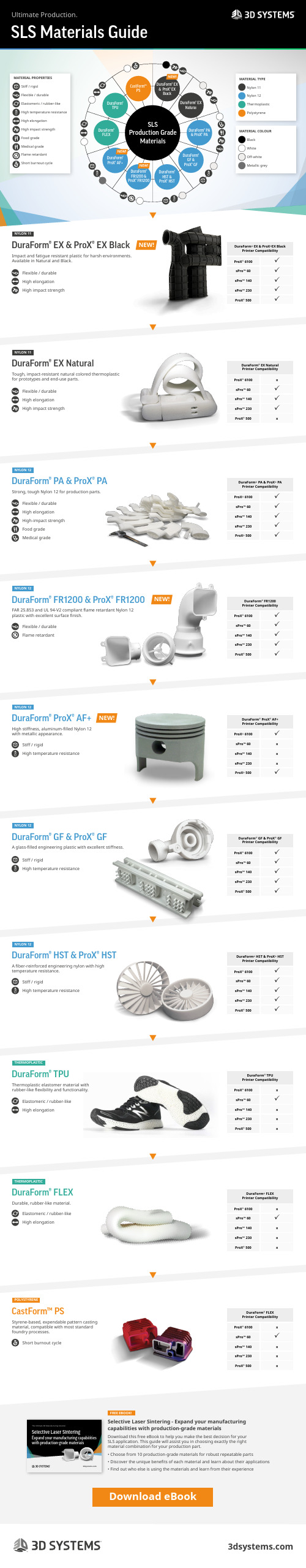
DuraForm® EX & ProX® EX BlackDuraForm® EX NaturalDuraForm® ProX® AF+DuraForm® TPUDuraForm® FLEXDuraForm® HST & ProX® HSTCastForm™PSDuraForm® PA & ProX® PADuraForm® FR1200 & ProX® FR1200DuraForm® GF & ProX® GFSLSProduction GradeMaterialsNEW!NEW!NEW!Flexible / durableFlame retardantStiff / rigidHigh temperature resistanceStiff / rigidHigh temperature resistanceStiff / rigidHigh temperature resistanceSLS Materials GuideUltimate Production.NEW!DuraForm® EX & ProX® EX BlackDuraForm® EX NaturalDuraForm® PA & ProX® PADuraForm® FR1200 & ProX® FR1200DuraForm® ProX® AF+DuraForm® GF & ProX® GFDuraForm® HST & ProX® HSTDuraForm® TPUDuraForm® FLEXCastForm™ PSNYLON 11NYLON 11NYLON 12NYLON 12NYLON 12NYLON 12NYLON 12THERMOPLASTICTHERMOPLASTICPOLYSTYRENEFREE EBOOK!DuraForm ® EX & ProX ®EX BlackPrinter Compatibility ProX ® 6100 sPro™ 60 sPro™ 140 sPro™ 230 ProX ® 500DuraForm ® EX Natural Printer Compatibility ProX ® 6100xsPro™ 60 sPro™ 140 sPro™ 230ProX ® 500xDuraForm ® PA & ProX ® PA Printer Compatibility ProX ® 6100 sPro™ 60 sPro™ 140 sPro™ 230 ProX ® 500DuraForm ® FR1200 Printer Compatibility ProX ® 6100 sPro™ 60 sPro™ 140 sPro™ 230 ProX ® 500DuraForm ® ProX ® AF+ Printer Compatibility ProX ® 6100sPro™ 60x sPro™ 140x sPro™ 230xProX ® 500DuraForm ® GF & ProX ® GF Printer Compatibility ProX ® 6100 sPro™ 60 sPro™ 140 sPro™ 230 ProX ® 500DuraForm ® HST & ProX ® HSTPrinter Compatibility ProX ® 6100 sPro™ 60 sPro™ 140 sPro™ 230 ProX ® 500DuraForm ® TPU Printer Compatibility ProX ® 6100xsPro™ 60sPro™ 140x sPro™ 230x ProX ® 500xDuraForm ® FLEX Printer Compatibility ProX ® 6100xsPro™ 60sPro™ 140x sPro™ 230x ProX ® 500xDuraForm ® FLEX Printer Compatibility ProX ® 6100xsPro™ 60sPro™ 140x sPro™ 230x ProX ® 500xFlexible / durable High elongationHigh impact strengthFlexible / durable High elongationHigh impact strengthFlexible / durable High elongation High-impact strength Food gradeMedical gradeImpact and fatigue resistant plastic for harsh environments. Available in Natural and Black.Tough, impact-resistant natural colored thermoplastic for prototypes and end-use parts.Strong, tough Nylon 12 for production parts.FAR 25.853 and UL 94-V2 compliant flame retardant Nylon 12 plastic with excellent surface finish.High stiffness, aluminum-filled Nylon 12 with metallic appearance.A glass-filled engineering plastic with excellent stiffness.A fiber-reinforced engineering nylon with high temperature resistance.Thermoplastic elastomer material with rubber-like flexibility and functionality.Durable, rubber-like material.Styrene-based, expendable pattern casting material, compatible with most standard foundry processes.Selective Laser Sintering - Expand your manufacturing capabilities with production-grade materialsDownload this free eBook to help you make the best decision for your SLS application. This guide will assist you in choosing exactly the right material combination for your production part.• Choose from 10 production-grade materials for robust repeatable parts • Discover the unique benefits of each material and learn about their applications• Find out who else is using the materials and learn from their experienceElastomeric / rubber-likeHigh elongationElastomeric / rubber-likeHigh elongationShort burnout cycleMATERIAL TYPE Nylon 11Nylon 12Thermoplastic PolystyreneMATERIAL COLOUR Black WhiteOff-whiteMetallic greyNEW!NEW!Download eBookMATERIAL PROPERTIES Stiff / rigid Flexible / durable Elastomeric / rubber-like High temperature resistance High elongation High impact strength Food grade Medical grade Flame retardantShort burnout cycleSelective Laser SinteringExpand your manufacturing capabilities with production-grade materialsThe Ultimate 3D Manufacturing Solution。

CC1N7781en Building Technologies Division7781Flame SafeguardsLAE10LFE10∙ Flame safeguards for burners with intermittent operation∙ The LAE10 is used for the supervision and indication of oil flames∙ The LFE10 is used for the supervision and indication of gas and oil flames ∙ Supplementary Data Sheets for flame detectors, refer to N7712 and N7713 ∙ For control units LEC1 for continuous operation, refer to Data Sheet N7761The LAE10 / LFE10 and this Data Sheet are intended for use by OEMs which integrate the flame safeguards in their products!Use∙ Flame safeguards for oil burners and oil units with or without a fan in accordance with DIN EN 60730-2-5:2005 and DIN EN 230:2005∙Flame safeguards for gas burners and gas-fired appliances with or without a fan in accordance with DIN EN 60730-2-5:2005 and DIN EN 298:2004Note!Do not use for new designs.∙ For the supervision of oil flames∙ Flame supervision with silicon photocell detector RAR9∙ For supervision of gas flames and luminous or blue-burning oil flames ∙ Flame supervision with flame detector QRA or ionization probeLAE10 LFE10Use (cont´d)GeneralBoth types of flame safeguards are used primarily in conjunction with LEC1 controlunits on the following applications:∙Dual-supervision of burners / supervision of the main flame or of the ignition andmain flame by 2 identical or different types of detectors∙Supervision of forced draft oil / gas burners / supervision of the flame withdifferent types of detectors, depending on the operating mode∙Multiflame supervision / plants with several burners whose flames must besupervised individually by one or several detectors, whose startup and supervision,however, should or must be carried out centrally and simultaneously by only 1burner control∙The flame safeguards can also be used in connection with other types of burnercontrols provided the given combination and selected connection circuit do notimpair the burner control’s safety functions∙The flame safeguards are also used as flame indication units in combustion plantwith manual startupWarning notesThe avoid injury to persons, damage to property or the environment, thefollowing warning notes must be observed!It is not permitted to open, interfere with or modify the units!∙All activities (mounting, installation and service work, etc.) must be performed byqualified staff. If this is not observed, there is a risk of loss of safety functions ora risk of electric shock∙For safety reasons – self-test of flame supervision circuit, etc. – at least onecontrolled shutdown is required every 24 hours. If this is not observed, there is arisk of loss of safety functions∙Before making any wiring changes in the connection area, completely isolate theplant from mains supply (all-polar disconnection). Ensure that the plant cannot beinadvertently switched on again and that it is indeed dead. If not observed, there isa risk of electric shock hazard∙Ensure protection against electric shock hazard by providing adequate protectionfor the flame safeguard´s connection terminals. If this is not observed, there is arisk of electric shock∙Each time work has been carried out (mounting, installation, service work, etc.),check to ensure that wiring is in an orderly state. If this is not observed, there is arisk of loss of safety functions or a risk of electric shock∙Fall or shock can adversely affect the safety functions. Such units must not be putinto operation, even if they do not exhibit any damage∙The ionization probe does not offer protection against electrical shock hazard. Themains-operated ionization probe must be protected against accidental contact. Ifthis is not observed, there is a risk of electric shock∙An ignited UV tube is a source of UV radiation! In case of flame supervision bymeans of flame detectors, the detectors must be placed such that there is nodirect visual contact between them. If this is not observed, there is a risk ofloss of safety functionsEngineering notesEnsure that the drop out delay time of relay «d» does not exceed 50 ms (also refer to«Connection examples», 7781a02).2/15Mounting notes∙The relevant national safety regulations must be complied with∙The flame safeguards can be mounted in any position directly on the burner, incontrol panels, or on the front of a panel∙There are 2 types of plug-in bases available, designed for cable entry from thefront, the side or below. 2 earth terminals provide looping facilities for the earthconnections of other burner plant components such as ignition transformers (theflame safeguards themselves are double-insulated!)Installation notes∙Always run the high-voltage ignition cables separately while observing the greatestpossible distances to the unit and to other cables∙Do not mix up live and neutral conductorsElectrical connection of the detectorsIt is important to achieve practically disturbance- and loss-free signal transmission:∙Never run the detector cable together with other cables– Line capacitance reduces the magnitude of the flame signal– Use a separate cable∙Ionization probe does not provide protection against electrical shock hazard∙Locate the ignition electrode and ionization probe such that the ignition sparkcannot arc over to the ionization probe (risk of electrical overloads)∙Observe the maximum permissible lengths and shielding of the detector cables(refer to «Technical data»)∙Locate and adjust the detector such that only the flame to be supervised will bedetected∙Protect the UV cell adequately against UV sources emitted by halogen lamps,welding equipments, special lamps, ignition sparks, high energy x-rays and gammarays3/154/15Standards and certificatesApplied directives:∙Directive for gas appliances 2006/95/EC∙Directive for gas-fired appliances (only LFE10) 2009/142/EC∙Directive for pressure devices 97/23/EC∙Electromagnetic compatibility EMC (immunity) *) 2004/108/EC*) The compliance with EMC emission requirements must be checked after the flame safeguard isinstalled in equipmentCompliance with the regulations of the applied directives is verified by the adherence tothe following standards / regulations:∙Automatic burner control systems for oil burners DINEN230∙ OnlyLFE10:Automatic burner control systems for burners and appliances burning gaseous or liquid fuelsDIN EN 298:2004∙Automatic electrical controls for household and similar use Part 2-5: Particular requirements for automatic electrical burner control systems DIN EN 60730-2-5The relevant valid edition of the standards can be found in the declaration of conformity!EAC Conformity mark (Eurasian Conformity mark)ISO 9001:2008ISO 14001:2004OHSAS 18001:2007China RoHSHazardous substances table:/download?A6V10883536WithLEC1…LAE10 ●●●●--- ●---LFE10 ●●●--- ●●●Life cycleFlame safeguards has a designed lifetime* of 250,000 burner startup cycles which,under normal operating conditions in heating mode, correspond to approx. 10 years ofusage (starting from the production date given on the type field).This lifetime is based on the endurance tests specified in standard EN 230 / EN 298.A summary of the conditions has been published by the European ControlManufacturers Association (Afecor) ().The designed lifetime is based on use of the flame safeguards according to themanufacturer’s Data Sheet. After reaching the designed lifetime in terms of the numberof burner startup cycles, or the respective time of usage, the flame safeguards is to bereplaced by authorized personnel.* The designed lifetime is not the warranty time specified in the Terms of DeliveryOnly in combinationwith the flame detector5/15Disposal notesThe flame safeguards contain electrical and electronic components and must not be disposed of together with household waste.Local and currently valid legislation must be observed.Mechanical designThe flame safeguards are of plug-in design and consist of power supply section, flame signal amplifier, flame relay, an auxiliary relay for controlling the flame detector or the flame simulation test, and a flame indication lamp located in the unit cover behind a viewing window.The electrical circuit is intrinsically safe in connection with LEC1 control unit – is tested in respect of proper functioning each time the burner is started up. The plug-in bases – like the housing – are made of impact-proof and heat-resistant plastic. For illustrations of the plug-in bases and other notes, refer to «Dimensions».Automatic light simulation test by increasing the sensitivity of the amplifier during the burner off and the purging times of the LEC1 control unit control.Automatic testing of the flame detector by increasing the operating voltage of the UV tube during the burner off and the purging times of the LEC1 control unit.Flame detector Data Sheet QRA2, QRA10 N7712 QRA4N7711RAR9 N7713Flame supervision by making use of the electrical conductivity of the flame inconjunction with the rectifying effect is only possible with gas and blue-flame burners. Since the flame signal amplifier responds only to the DC component of the flame signal (ionization current), a short-circuit between flame detector and functional earth cannot simulate a flame signal.Type summaryWhen ordering, please give complete type reference.Flame safeguard is delivered without plug-in base; order these separately (refer to «Accessories»).∙ For the supervision of oil flames with silicon photocell detectors RAR9...Article no. Type AC 220…240 VBPZ:LAE10LAE10AC 110 V BPZ:LAE10-110V LAE10-110V∙ For the supervision of gas / oil flames with flame detector QRA or ionization probeArticle no. Type AC 220…240 V BPZ:LFE10 LAE10 AC 110 VBPZ:LFE10-110VLAE10-110VSpecial features LAE10Special features LFE10FlamesupervisionIonization probeFlame safeguardAccessories (must be ordered separately)Flame detectorSilicon photocell detectors RAR9Refer to Data Sheet N7713UV flame detector QRA2Refer to Data Sheet N7712UV flame detector QRA10...Refer to Data Sheet N7712UV flame detector QRA4...Refer to Data Sheet N7711Ionization probeSupplied by thirdsPlug-in baseLow plug-in base (refer to «Dimensions») AGK410413450Article no.: BPZ:AGK410413450∙10-pole screw terminals∙ 5cableentriesHigh plug-in base (refer to «Dimensions») AGK410490250 Article no.: BPZ:AGK410490250∙10-pole screw terminals∙With removable front∙6 cable entries, 4 of which with Pg11 thread6/15Technical dataMains voltage AC 220 V –15 %...AC 240 V +10 %General unit dataAC 100 V –15 %...AC 110 V +10 %Mains frequency 50...60 Hz ±6 %Prefuse (external) Max. 10 A (slow)Power consumption 4.5 VAPerm. contact rating Max. 2 ADegree of protection IP40, with appropriate cable entryMounting position OptionalCross sectional areas that can beconnected to AGK4∙Terminal 1...10 Min. 0,75 mm²Max. 1,5 mm²Solid wire or stranded wire with ferrule∙Auxiliary terminals N, PE, 11 and 12 Min. 0,75 mm²Max. 1,5 mm²Solid wire or stranded wire with ferrule (whenconnecting 2 solid wires or stranded wires perterminal, same cross-sectional areas must beused)Weight LAE10 LFE10Without plug-in base Approx. 305 g Approx. 395 gWith normal plug-in base Approx. 380 g Approx. 470 gWith high plug-in base Approx. 415 g Approx. 505 gLAE10 LFE10Flame supervision with......RAR9 ...Ionization probe ...QRARequired detector current- At AC 100 V / AC 220 V Min. 8 µA Min. 8 µA Min. 150 µA- At AC 110 V / AC 240 V Min. 8 µA Min. 9 µA Min. 200 µAPossible detector current- At AC 100...110 V / AC 220...240 V Max. 38 µA Max. 100 µA Max. 650 µAPerm. length of connecting cables 20 m ²) 20 m ¹) 20 m ¹)¹) In case of greater distances, use low-capacitance cable (total max. 2 nF)Example: Single-core RG62²) Run detector cables separately, at least 5 cm away from other cables7/158/15Technical data (cont´d) Storage DIN EN 60721-3-1 Climatic conditions Class 1K3 Mechanical conditions Class 1M2 Temperature range -20...+60 °CHumidity <95 % r.h. Transport DIN EN 60721-3-2 Climatic conditions Class 2K2 Mechanical conditions Class 2M2 Temperature range -20...+60 °CHumidity <95 % r.h. Operation DIN EN 60721-3-3 Climatic conditions Class 3K5 Mechanical conditions Class 3M2 Temperature range -20...+60 °CHumidity <95 % r.h. Installation altitude Max. 2,000 m above sea levelCaution!Condensation, formation of ice and ingress of water are not permitted!If this is not observed, there is a risk of loss of safety functions and a risk of electric shock.Ionization probe QRA RAR9QRA...AM +-LFE10109C-+AM +-910LAE107781a07/0908-++A Illumination of flame C Electrolytic capacitor 100 µF, DC 10 V ION Ionization probe M Microammeter QRA... Flame detectorCaution!Ignition may affect the ionization current!Remedy: Exchange the connections on the primary side of the ignition transformer.Environmental conditionsMeasuring circuitsLegendFunctionBasic mode of operation of the flame safeguards in connection with the LEC1 controlunit:When used with the LEC1, the flame safeguard feeds the flame signal into the burnercontrol’s control program the same way as if the flame safeguard was a component ofthe burner control (same as with an oil or gas burner control). In the event of non-ignition, loss of flame during burner operation or faulty flame signal during burner off orpurging times, the burner will always be shut down and the burner control will initiatelockout. The switching functions needed to feed the flame signal into the burnercontrol’s control circuit are provided by flame relay «FR» of the flame safeguard andthe 2 auxiliary relays «HR1» and «HR2» of the LEC1 control unit. The LEC1 controlunit also delivers the sequence control for the flame simulation test in connection withthe LAE10 flame safeguard, and the flame detector test with the LFE10. The test iscontrolled via the connecting line between terminal 15 of the burner control andterminal 6 of the respective flame safeguard.Both tests∙start about 7 seconds after a controlled shutdown∙are continued during burner off times∙Are continued during the ensuing prepurge time∙end 3 seconds before start of the safety timeFollowing flame signals during this test time lead to lockout with interlocking of theLEC1 control unit:∙ Extraneouslight∙ Ageingflamedetectors∙Other defects of the flame supervision equipmentIn the flame safeguard, the switching functions required are performed by auxiliaryrelay «HR3».Since in the case of flame supervision with an ionization probe, it is not necessary tocarry out a test, the connecting line between terminal 15 of the burner control andterminal 6 of the flame safeguard is not required here.Information!Instead, terminal 6 must be connected to the live wire.Example: By making a connection to terminal 1, 5 or 7.Any flame signal – be it a normal flame signal during operation or a faulty signal – is indicated by the indication lamp at housing of flame safeguard.9/15Mode of operation of the flame safeguards when used for dual-supervision (detailed connection diagram, e.g. for oil burners)With this type of supervision, 1 flame is supervised by 2independently operating flame safeguards, aimed atreducing the possibility of loss of flame during operationin case of a simultaneous failure of both flamesafeguards to an «improbable coincidence».With dual-supervision, the control contacts of the flamerelays of both flame safeguards are connected in seriesso that loss of the flame signal of either of the flamesafeguards is sufficient to cause lockout of the burner.A faulty flame signal by only 1 of the 2 flame safeguardsduring burner off times or purging times also leads tolockout.10/15Mode of operation of the flame safeguards when used for the supervision of 2 manually controlled burnersstarted only if the flame detector or flame simulation testhas been successful. This means that neither of the 2flame safeguards may detect a flame signal during burneroff times. When the burner is started up, the detector testwill automatically be interrupted.When pressing button «I», relay «d» is energized viacircuit path 4-5 of the flame relays, which is still closed,thus switching on the ignition of both burners.At the same time, fuel is released.The duration of the start pulse given by pressing button«I» should be limited by a time relay – in the sense of asafety time.If the flame is established on both burners - indicated bythe signal lamps at housing of flame safeguards – relay«d» is now maintained in its energized condition viacircuit path 3-7 of the 2 flame relays.When releasing button «I», ignition will be switched off,thus completing the startup sequence.If the event of loss of flame on 1 of the burners, therespective flame relay is deenergized, therebyneutralizing the holding circuit for relay «d». This meansthat the fuel valves of both burners will immediately beshut.The burners are switched off manually be pressing button«0», or – automatically – by the control / limit thermostator pressurestat / pressure switch in the phase wireconnection.In case of flame supervision with ionization probes,terminal 6 of the flame safeguards must be connecteddirectly to the phase wire since no detector test isrequired here.Example: During connection with terminal 1!Note!Ensure that the drop out delay time of relay «d» does not exceed 50 ms (also refer to«Connection examples», 7781a02).Caution!An ignited UV tube is a source of UV radiation! In case of flame supervision bymeans of flame detectors, the detectors must be placed such that there is no directvisual contact between them. If this is not observed, there is a risk of loss of safetyfunctionsMode of operation of the flame safeguards with multi-flame supervision (detailed connection diagram, e.g. for gas burners)P(R)Like with dual-supervision, the control contactsof the flame relays of all flame safeguards mustbe connected in series when using multi-flamesupervision.A burner causes all other burners to go tolockout if:∙the flame is not established during thesafety timeor∙the flame is lost during operation.Correctly operating burners can be restartedonly – after the burner control has been reset –when the faulty burner has been shut down.In that case, the operating switch must not onlybridge the control contacts of the respectiveflame safeguards, thus closing the control chainagain, but must also break the phase wireconnection to the ignition transformer and thefuel valves.Likewise, after rectification of the fault, theburner can only be restarted in connection withthe other burners, that is, only after all burnershave previously been shut down.Caution!Terminal 10 must be connected toearth also when using the flamedetector QRA!BS Operating switch OFF / ON → per burnerION Ionization probe for ionization supervisionFR FlamerelayGV1 / GV2 Gas valve for 1st and 2nd stageL1 Built-in signal lamp → indication of flameQRA... FlamedetectorZ IgnitiontransformerLegendBasic circuit diagrams LFE10 with flame detector QRA1314LEC1Caution!Terminal 10 must be connected to earth!LFE10 with ionization supervisionLAE10 with silicon photocell detector RAR9...Legend1314LEC1FR Flame relay H Main switchHR3 Auxiliary relay for UV detector or flame simulation testIONIonization probe for ionization supervision L1 Built-in signal lamp Indication of flame QRA... Flame detectorRAR9...Silicon photocell detectorDimensionsDimensions in mm Base versionsLow plug-in base, AGK 4 104 1345 0Design features:10-pole (screw terminals), with additional earth terminals. Cable entry either through the bottom of the base (2 knockout holes), the front, from the right or left side (total of 5 cable entries).7781m02/1198Dimensions (cont´d)Dimensions in mm Base versionsHigh plug-in base, AGK 4 104 9025 0Design features:With removable front (shaded area in the drawing).10-pole (screw terminals), and:∙ 2 auxiliary terminals with markings 11 and 12∙ 2 neutral terminals, wired to terminal 2 (neutral input)∙ 2 earth terminals, with earthing lug for the burnerFor cable entry:∙ 2 cable entries in the bottom of the base∙ 4 threaded knockout holes for cable glands Pg11, 1 on the right, 1 on the left, and in the removable front7781m01/1198© 2016 Siemens AG Building Technologies Division, Berliner Ring 23, D-76437 RastattSubject to change!。

LFL英⽂说明书7451Burner Controls LFL1...Burner controlsFor gas, oil or dual-fuel forced draft burners of medium to high capacityFor multistage or modulating burners in intermittent operationWith checked air damper controlFlame supervision– with UV detectors QRA...– and ionization probeThe LFL1... and this Data Sheet are intended for use by OEMs which integrate theburner controls in their products!Use-Control and supervision of forced draft burners of expanding flame or interruptedpilot construction-For medium to high capacity-For intermittent operation (at least one controlled shutdown every 24 hours)-For universal use with multistage or modulating burners-For use with dual-fuel burners-For use with stationary air heatersThe difference between 01 series and 02 series is the duration of the safety time for thepilot burner of burners equipped with pilot gas valves.For atmospheric burners of high capacity, use the LFL1.638.For burner controls suited for continuous operation, refer to Data Sheet N7785(LGK16...).Building Technologies CC1N7451enWarning notesTo avoid injury to persons, damage to property or the environment, the following Array warning notes should be observed! Do not open, interfere with or modify the unit!All activities (mounting, installation and service work, etc.) must be performed byqualified staffBefore performing any wiring changes in the connection area of the LFL1…, com-pletely isolate the unit from the mains supply (all-polar disconnection)Ensure protection against electric shock hazard by providing adequate protection for the burner control’s connection terminalsEach time work has been carried out (mounting, installation, service work, etc.), check to ensure that wiring is in an orderly state and make the safety checks as described in ?Commissioning notes?Press the lockout reset button only manually (apply a force of no more than 10 N), without using any tools or pointed objectsDo not press the lockout reset button on the unit or the remote lockout resetbutton for more than 10 seconds since this damages the lockout relay in theunitFall or shock can adversely affect the safety functions. Such units must not be put into operation, even if they do not exhibit any damageIn the case of flame supervision with UV detectors QRA..., it should be noted that sources of radiation such as halogen lamps, welding equipment, special lamps, ig-nition sparks, as well as X-rays and gamma radiation, can produce erroneousflame signalsMounting notesEnsure that the relevant national safety regulations are complied withWhen using 2 UV detectors QRA..., make certain that the detectors cannot see one anotherInstallation notesAlways run the high-voltage ignition cables separately while observing the greatest possible distance to the unit and to other cablesDo not mix up live and neutral conductorsElectrical connection of flame detectorsIt is important to achieve practically disturbance- and loss-free signal transmission: Never run the detector cable together with other cables– Line capacitance reduces the magnitude of the flame signal– Use a separate cableObserve the maximum permissible detector cable lengths (refer to Technical data) 2 UV detectors QRA... can be connected in parallelIn connection with the QRA..., earthing of terminal 22 is mandatoryThe ionization probe is not protected against electric shock hazardLocate the ignition electrode and ionization probe such that the ignition spark can-not arc over to the ionization probe (risk of electrical overloads)Supervision with both ionization probe and UV detector QRA... is possible, but forsafety reasons – with the exception of the second safety time ?t9? – only 1 flamedetector may be active at a time. At the end of the second safety time, 1 of the de-tectors must be inactive, however, that is, the detected flame must have extin-guished, e.g. by switching off the ignition valve via terminal 172/18Commissioning notesWhen commissioning the plant or when doing maintenance work, make the follow-ing safety checks:Safety check to be carried out Anticipated responsea) Burner start with flame detector dark-enedLockout at the end of ?TSA?b) Burner start with flame detector ex-posed to extraneous light Lockout after no more than 40 secondsc) Burner operation with simulated loss offlame; for that purpose, darken theflame detector in operation and maintainthat state (not possible with ionization)LockoutEngineering notesInstall switches, fuses, earthing, etc., in compliance with local regulationsDecisive for the connection of the valves and other plant components is the plant34567 127451a14e/0604c Connect safety limit thermostat in the line (manual reset, e.g. ?SB?)d Remote resetWhen remote reset button ?EK2? is connected between terminal 21 and- terminal 3, only remote reset is possible- terminal 1, both remote emergency shutdown and remote reset are possiblee Required switching capacities- of the switching devices connected between terminals 12 and 4 (refer to ?Technical data?) - of the switching devices connected between terminals 4 and 14 (refer to ?Technical data?) - depending on the loads applied to terminals 16...19 (refer to ?Technical data?)f Air pressure supervisionIf the air pressure is not monitored with air pressure switch ?LP?, terminal 4 must be connected to terminal 12, and terminal 6 to terminal 14. Terminal 13 is not used.Control contacts of the other devices in the burner installation – if series-connected – are to be connected as follows:- To terminal 4 or 5 → contacts which must be closed from startup to controlled shutdown → otherwise no start or shutdown -To terminal 12 → contacts which must only be closed on startup → otherwise no start- To terminal 14 → contacts which must be closed at the beginning of the preignition time at the latest, and which must stay closed until controlled shutdown occurs → otherwise lockout; this applies to both long and short preignitiong? Connection of fuel valves with expanding flame burners. With 2-stage burners, ?BV2? is connected in place of ?BV3? ?? Connection of fuel valves with interrupted pilot burnersDirect connection of a fuel valve to terminal 20 is only permitted-in plants with a main shutoff valve on the mains side (safety shutoff valve), which is controlled by terminal 18 or 19, and -if 2-stage valves are used, provided they fully close when the first stage, controlled by terminal 18 or 19, is switched off h For additional examples of air damper control, refer to ?Connection examples?. In the case of actuators with no end switchz for the fully CLOSED position of the air damper, terminal 11 must be connected to terminal 10 → otherwise no burner start.i Simultaneous use of ionization and UV supervision is possible3/184/18Standards and certificatesConformity to EEC directives- Electromagnetic compatibility EMC (immunity) - Low-voltage directive- Directive for gas appliances89 / 336 / EEC 73 / 23 / EEC 90 / 396 / EECISO 9001: 2000 Cert. 00739 ISO 14001: 2004 Cert. 38233Certified complete with plug-in base and flame detector:Type referenceLFL1.122 x --- xx x x x x LFL1.133 x --- x x --- x x --- LFL1.322 x --- x x x x x x LFL1.333 x --- x x x x x --- LFL1.335 x x x x x x x x LFL1.622 x ---x x x x x x LFL1.635 x --- x x x x x x LFL1.638 x --- x--- x ---x---Identification code to EN 298– All types (except LFL1.148) F B L L X NDisposal notesThe unit contains electrical and electronic components and must not be disposed of together with domestic waste.Local and currently valid legislation must be observed.Mechanical design - Plug-in design- Exchangeable unit fuse (including spare fuse)- Made of impact-proof and heat-resistant black plastic - Lockout reset button with viewing window showing– the fault signal lamp – the lockout indicator- coupled to the program spindle- visible in the transparent lockout reset button- uses easy-to-remember symbols to indicate the type of fault and the time lockout occurredLFL1...Housing5/18Type summarySwitching times are given in seconds, in the burner startup sequence, valid for 50 Hz mains frequency. At 60 Hz, switching times are about 17 % shorter.Flash steam generators Flash steamgeneratorsD (incl. sta-tionary air heaters) FA D GB F I B NL 2) Large at-mosphericburners LFL1.122 1) 02 series LFL1.133 1) 02 series LFL1.322 1)02 series LFL1.333 1)02 series LFL1.335 1)01 series LFL1.622 1) 02 series LFL1.635 1)01 series LFL1.63801 seriest1 10 9 36 31 37 65 66 66 TSA 2 3 2 3 2.5 2 2.5 2.5 TSA′ 2 3 2 3 5 2 5 5 t3 4 3 4 6 5 4 5 5 t3′ 4 --- 4 6 2.5 4 2.5 2.5 t4 6 6 10 11.5 12.5 10 12.5 12.5 t4′ 6 --- 10 11.5 15 10 15 15 t5 4 3 10 11.5 12.5 10 12.5 12.5 t6 10 14.5 12 17 15 12 15 15 t7 2 3 2 3 2.5 2 2.5 2.5 t8 30 29 65 69 74 95 103 103 t9 2 3 2 3 5 2 5 7.5 t10 6 6 8 11.5 10 8 10 10 t11 Optional t12 Optionalt13 10 14.5 12 17 15 12 15 15 t16 4 3 4 6 5 4 5 5 t20 32 60 --- 26 22 --- --- ---1) Available as AC 100...110 V versions; add type suffix ?-110 V? when ordering 2) Reversed polarity protection conforming to Dutch installation standard: AGM30OrderingBurner control , without plug-in base see ?Type summary? Plug-in base not included in delivery, must be ordered as a separate item!Connection accessories for medium-capacity burner controls see Data Sheet N7230 - Plug-in base AGM410490550 with Pg11 thread for cable entry glands - Plug-in base AGM14.1 with M16 thread for cable entry glandsFlame detectors- Flame detectors QRA... refer to Data Sheet N7712 - Ionization probe to be supplied by thirdsTest unit KF8806 for burner control see Operating Instructions B7987 - For simulating faults- For checking the pull-in and drop-out values of the flame relay in the case of flame supervision with flame detector QRA... or ionization probeTest unit KF8804 for burner control- Tool to assist startup, with the possibility of program stop and measurement of the flame current6/18Technical data Mains voltageAC 230 V –15 / +10 % AC 115 V –15 / +10 %Mains frequency 50...60 Hz ±6 % Unit fuse (built-in) T6.3H250V to DIN EN 60 127 Primary fuse (external) max. 10 A (slow) Weight approx. 1,000 g Power consumption approx. AC 3.5 VA Mounting position optional Degree of protection IP 40, when built in, with the exception ofthe connection area (terminal base) Safety classII Perm. input current at terminal 1 max. 5 A continuously (peaks 20 A / 20 ms)Perm. load on control terminals 3, 6, 7, 9...11, 15 (20)max. 4 A continuously (peaks 20 A / 20 ms)Required switching capacity of switching devices- Between terminals 4 and 5- Between terminals 4 and 12- Between terminals 4 and 141 A, AC 250 V 1 A, AC 250 V min. 1 A, AC 250 V depending on the load on terminals 16 (19)Storage DIN EN 60721-3-1 Climatic conditions class 1K3 Mechanical conditions class 1M2 Temperature range -20...+60 °C Humidity < 95 % r.h. Transport DIN EN 60721-3-2 Climatic conditions class 2K3 Mechanical conditions class 2M2 Temperature range -20...+60 °C Humidity < 95 % r.h. Operation DIN EN 60 721-3-3 Climatic conditions class 3K3 Mechanical conditions class 3M3 Temperature range -20...+60 °C Humidity < 95 % r.h.Condensation, formation of ice and ingress of water are not permitted!Voltage at the ionization probe - Operation - Test AC 330 V ±10 % AC 380 V ±10 % Short-circuit current max. 0.5 mA Recommended range of measuring instrument0...50 µA Perm. length of detector cable - Normal cable, laid separately 2) - Shielded cable max. 80 m max. 140 m (e.g. high-frequency cable;shielding connected to terminal 22)Required detector current in operation min. 6 µA Possible detector current in operation max. 200 µAGeneral unit data LFL1...Environmental conditionsFlame supervision with ionization probe7/18Technical data (cont′d)Supply voltage - Operation - TestAC 330 V ±10 % AC 380 V ±10 % Required detector current min. 70 µA Possible detector current - Operation - Test max. 700 µA max. 1000 µA 1) Perm. length of detector cable - Normal cable, laid separately 2) - Shielded cablemax. 100 mmax. 200 m (e.g. high-frequency cable; shielding connected to terminal 22)1) During the prepurge time with higher test voltage: Self-ignition and extraneous light test 2) Multicore cable not permitted Ionization probe Flame detector QRA...LFL1...247451v01/0204MC++-ION7451v02/0204AM C2322LFL1...-+-+QRA...For detector currents, refer to ?Technical data?.C Electrolytic condenser 100...470 µF; DC 10...25 V ION Ionization probeMMicroammeter Ri max. 5,000 Ω Flame supervision with flame detector QRA...Measuring circuit for detector current measurementLegendFunction2-stage expanding flame burnerModulating expanding flame burner7451a07/06002-stage interrupted pilot burner7451a08/0202LegendBV... Fuel valveFS Flame signal amplifierLK AirdamperLR LoadcontrollerM... Fan or burner motorR Control thermostat or pressurestatRV ModulatingfuelvalveZ IgnitiontransformerZBV Pilot gas valveA Start command by ?R?B Operating position of burnerB-C BurneroperationC ControlledshutdownC-D Sequence switch travels to start position ?A?, postpurging D-A End of control sequencet1 Prepurge time with air damper fully open t3/t3′ Preignition time t4/t4′ Interval ?BV1-BV2? or ?BV1-LR?t5 Interval between voltage at terminal19 and terminal 20t6 Postpurgetimet7 Interval between start command and voltage at terminal 7t9 2nd safety time with burners equipped with a pilot burnert11 Air damper’s running time to the fully OPEN positiont12 Air damper’s running time to the low-fire positiont13 Permissible afterburn timeTSA/TSA′ Ignition safety time8/189/18Function (cont′d)The following features enable the LFL1... to offer a high level of additional safety:- Detector and extraneous light test are resumed immediately on completion of theafterburn time ?t13?. Fuel valves that are not closed, or not fully closed, immedi-ately initiate lockout on completion of the afterburn time ?t13?. The test will only be terminated when the prepurge time ?t1? of the next startup sequence has elapsed. - The proper functioning of the flame supervision circuit is automatically checkedduring each startup phase of the burner.- During the postpurge time ?t6?, the control contacts for the release of fuel arechecked to ensure they have not welded.- The built-in unit fuse protects the control contacts against overloads.- Burner operation with or without postpurging- Fan motors with a current draw of up to 4 A can be connected directly → startingcurrent max. 20 A (max. 20 ms)- Separate control outputs for one pilot valve, which will be shut on completion of thesecond safety time- Separate control outputs for the actuator’s positioning directions ?OPEN?,CLOSE and MIN- Checked air damper control to ensure prepurging with the nominal amount of air - Checked positions:- ?CLOSED? or ?MIN? on startup → low-fire position - ?OPEN? at the start of prepurging - ?MIN? on completion of prepurgingIf the actuator does not drive the air damper to the required position, the burner startup sequence will be stopped- 2 control outputs for the release of the second and third output stage, or load control - When load control is enabled, the control outputs for the actuator will galvanicallybe separated from the unit’s control section - Connection facilities for- remote lockout warning device - remote reset- remote emergency shutdown- With burner controls of the 01 series and expanding flame burners, the safety timecan be increased from 2.5 to 5 seconds by changing the circuitry (refer to ?Connec-tion examples?), provided the longer safety time conforms to local safety regulations- With the ionization probe, in networks with earthed or nonearthed neutral conduc-tor. For this kind of supervision, the flame supervision circuit is designed such that possible disturbances of the ionization current due to the ignition spark normally have no impact on the establishment of the flame signal. A short-circuit between ionization probe and burner ground causes loss of the flame signal - With UV detector QRA... (gas and oil burners)- Simultaneous use of ionization probe and UV detector QRA... (e.g. with interruptedpilot burners or gas-electrically ignited oil burners)- If, on startup, the required input signals are not present, the burner control inter-rupts the startup sequence at the points marked by symbols and initiates lockout where required by safety regulations. The symbols used in this Data Sheet corre-spond to those on the burner control’s lockout indicator.- Burner control must be reset- Sequence switch must be in its start position → voltage at terminals 4 and 11 present - Air damper closed- End switch ?z? for the ?CLOSED? position must feed voltage from terminal 11 toterminal 8- The contacts of control thermostat or pressurestat ?W? and other contacts ofswitching devices connected between terminal 12 and ?LP? must be closed → e.g. control contact for the oil preheater’s temperature - Terminal 4 must be live- The N.C. contact of the air pressure switch must be closed → ?LP? testGeneralControl of the burnerFlame supervisionPreconditions for startupPreconditions for burner startupStartup sequenceA Start command delivered by ?R?→ ?R? closes the start control loop between terminals 4 and 5-The sequence switch starts running- Only prepurging, power is immediately fed to the fan motor connected to terminal 6- Pre- and postpurging; on completion of ?t7?, power is fed to the fan motor or flue gas fan connectedto terminal 7-On completion of ?t16?, the control command to open the air damper is delivered via terminal 9-No power is fed to terminal 8 during the positioning time-The sequence switch continues its travel only after the air damper has fully openedt1 Prepurge time with air damper fully open-During ?t1?, the correct functioning of the flame supervision circuit is tested-If test is not successful, the burner control will initiate lockoutShortly after the start of ?t1?, the air pressure switch must change over from terminal 13 to terminal 14.→ Otherwise lockout→ Start of air pressure checkAt the same time, terminal 14 must be live since the ignition transformer will be powered and the fuel re-leased via this current path.On completion of the prepurge time, the burner control will drive the air damper to the low-fire position via terminal 10, which is determined by the changeover point of auxiliary switch ?m?. During the positioning time, the sequence switch stops again.A short time later, the motor of the sequence switch will be switched to the control section of the burner control. This means that, from now on, positioning signals delivered to terminal 8 have no impact on the burner’s further startup sequence (and on subsequent burner operation):t5 Interval-On completion of ?t5?, power is fed to terminal 20; at the same time, control outputs 9...11 and input 8 are galvanically separated from the unit’s control section→ The LFL1... is now protected against return voltages from the power control loop-The startup sequence of the LFL1… ends with the release of ?LR? at terminal 20-After a number of idle steps (steps with no change of the contact position), the sequence switch switches itself off Expanding flame burnerstimesafetyTSA IgnitionOn completion of ?TSA?, a flame signal must be present at terminal 22. It must not be interrupted until con-trolled shutdown takes place → otherwise lockouttimet3 PreignitionRelease of fuel via terminal 18t4 Interval ?BV1 – BV2? or ?BV1 - LR?-On completion of ?t4?, terminal 19 is live-That powers ?BV2? connected to the actuator’s auxiliary switch ?v?10/18Startup sequence (cont′d) Interrupted pilot burnerst3 t3′ Preignition timeRelease of fuel for pilot burner via terminal 17TSA TSA′ Ignition safety timeOn completion of ?TSA?, a flame signal must be present at terminal 22. It must not be interrupted until con-trolled shutdown takes place→ otherwise non-volatile lockoutt4 t4′ Interval ?ZBV-BV1?Up to the release of the fuel valve at terminal 19 for the main burner’s start loadt9 Second safety timeOn completion of the second safety time, the main burner must have been ignited by the pilot burner sinceterminal 17 becomes dead as soon as this time has elapsed, causing the pilot valve to closeB Operating position of the burnerB-C Burneroperation-During burner operation, ?LR? drives the air damper to the high-fire or low-fire position, depending on the demand for heat -Release of high-fire is enabled by auxiliary switch ?v? in the actuator-In the event of loss of flame during operation, the LFL1… will initiate lockoutC ControlledshutdownOn controlled shutdown, the ?BV...? will immediately be closed. At the same time, the sequence switchstarts and programs ?t6?C-D The sequence switch travels to start position ?A?, postpurgingWhen burner off time starts, control terminals 11 and 12 carry voltage to drive the air damper to the fullyCLOSED position. Flame signal supervision also remains active during burner off timest6 Postpurgetime-Fan ?M2? connected to terminal 7-Shortly after the start of ?t6?, power is fed to terminal 10→ air damper will be driven to the MIN position-Full closing of the air damper starts only shortly before ?t6? has elapsed→ triggered by the control signal at terminal 11-During the following burner off period, terminal 11 remains livet13 PermissibleafterburntimeDuring ?t13?, the flame signal input can still receive a flame signal→ no lockoutD-A End of control sequence→ start positionAs soon as the sequence switch has reached the start position – thereby switching itself off – the flame de-tector and extraneous light test will start again.During burner off periods, the flame supervision circuit is live. A faulty flame signal of a few seconds willinitiate lockout.Short ignition pulses of the UV tube, caused for instance by cosmic radiation, do not lead to lockout.Times ?TSA′?, ?t3′? and ?t4′? only exist with burner controls of the 01 series.11/1812/18Control sequence under fault conditions and lockout indicationIn the event of any kind of fault, the sequence switch will stop and, with it, the lockout indicator.The symbol above the indicator’s reading mark gives the type of fault:One of the contacts is not closed (also refer to Preconditions for burner startup)No startExtraneous lightLockout during or after completion of the control sequence. Examples:– Flames that have not extinguished – Leaking fuel valves– Defect in the flame supervision circuitTerminal 8 has not received the OPEN signal from end switch a =Interruption of startup sequence ? Terminals 6, 7 and 14 remain live until the fault has been correctedNo indication of air pressure at the beginning of the air pressure check P LockoutLoss of air pressure after the air pressure checkLockout ? Defect in the flame supervision circuitTerminal 8 has not received the positioning signal from auxiliary switch m for thelow-fire position>Interruption of startup sequence ? Terminals 6, 7 and 14 remain live until the fault has been corrected1 Lockout ? No flame signal on completion of safety time ?TSA?2 Lockout ? No flame signal on completion of the second safety time (flame signal of main flamewith interrupted pilot burners)ILockoutLoss of flame signal during operationIf lockout occurs any other moment in time between start and preignition not indicated by a symbol, the usual cause is a premature flame signal, that is, a faulty flame signal, caused for instance by a self-igniting UV tube.a-b Startup sequenceb-b′ Idle steps (with no contact confirmation)b (b′)-a Postpurge programLFL1... Serie 01 LFL1... Serie 02If lockout occurs, the burner control can immediately be reset: – Do not press the lockout reset button for more than 10The sequence switch always returns to its start position first – After resetting– After correction of a fault which resulted in plant shutdown – After each power failureDuring that period of time, power is only fed to terminals 7 and 9...11. ?Then, the LFL1... begins with a new burner startup sequenceLockout indicatorConnection diagrams (for circuit variants, refer to ?Connection examples?)34567 127451a02e/0604Connection diagram (for circuit variants, refer to ?Connection examples?)EK1Do not press lockout reset button ?EK...? for more than 10 seconds!For the connection of the safety shutoff valve, refer to the plant diagram provided bythe burner manufacturer.13/1814/18Program sequenceControl output I II III IV V VI VII VIII X XIXIIXIII XIVa b a b a ba ba b a b a b a ba b a ba b XVa bTSA′?, ?t3′? and ?t4′?:These times only apply to burner controls of the 01 series (LFL1.335, LFL1.635, and LFL1.638). They do not apply to burner controls of the 02 series since cams X and VIII of these types of LFL1… perform simultaneous switching actions.Legenda Changeover end switch for air damper’s m Changeover auxiliary switch for the airOPEN position damper’s MIN positionAL Remote lockout warning device (alarm) M... Fan or burner motorAR Load relay with contacts ?ar...? NTC NTC resistorfuse QRA... UVdetectorBR Lockout relay with contacts ?br...? R Control thermostat or pressurestatBV... Fuel valve RV Modulating fuel valvebv... Control contact for the CLOSED position Si External fuseof gas valves SA Air damper actuatord... Contactor or relay SB Safety limiterEK... Lockout reset button SM Synchronous motor of sequence switchFR Flame relay with contacts ?fr...? v In the actuator: Changeover auxiliary switch GP Gas pressure switch For the position-dependent release of fuelH Main isolator V Flame signal amplifierION Ionization probe W Limit thermostat or pressure switchL1 Fault signal lamp z In the actuator: End switch for the air damper’s L3 Operational readiness indication CLOSED position LK Air damper Z Ignition transformerLP Air pressure switch ZBV Pilot gas valveLR LoadcontrollerControl signals of the LFL1...Permissible input signalsRequired input signals:If these signals are not present during orinitiate lockoutTSA Ignition safety time t8 Duration of startup sequenceTSA′ Ignition safety time or first safety time (without ?t11? and ?t12?)(startup with burners using pilot burners) t9 Second safety time with burners using pilot burners t1 Prepurge time with air damper open t10 Interval from start to the beginning of thet3 Preignition time air pressure check, excluding running time of airt4 Interval between voltage at terminals 18 damperand 19 t11 Air damper running time to the OPEN positiont4′ Interval between start of TSA′ and t12 Air damper running time to the low-fire position release of valve at terminal 19 MIN t5 Interval between power at terminals 19 t13 Permissible afterburn timeand 20 t16 Interval until OPEN command for the air damper is t6 Postpurge time (with ?M2?) givent7 Interval between start command and power t20 Interval to the self-shutdown of the sequence at terminal 7 (start delay for ? M2?) switch after startupValid for expanding flame burners。

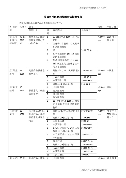
美国各州阻燃剂检测测试标准要求上海标检产品检测有限公司提供其中美国加利福尼亚州州长于2018年9月29日已签署法案AB 2998,从2020年1月1日起,禁止青少年产品,床垫和软垫家具中的阻燃剂含量在1000 ppm以上。
这些规定将加入到《商业和专业法令》第8部分第3章中。
禁令详情如下:1. 从2020年1月1日或之后,包括制造商在内的任何人不得在商业中销售或分销任何新的,非现有的含阻燃剂含量超过1000 ppm的青少年产品,床垫或软垫家具。
2. 从2020年1月1日或之后,定制家具商不得使用含有高于1000 ppm所涵盖阻燃剂的替换部件来维修,重装,恢复或更新软垫家具。
3. 上述(1)和(2)的禁令不适用于以下情况:a. 青少年产品,床垫,重装软垫家具或软垫家具的电子元件,或电子元件的相关外壳;b. 除《商业和专业法令》第19094条(a)部分第(1)段所述的家具部件以外的软垫家具或重装软垫家具部件;c. 用于将床垫部件缝合在一起的线或纤维;d. 除泡沫之外的成人床垫部件。
“成人床垫”是指除了幼儿床垫,婴儿床垫和其他婴儿睡眠产品之外的床垫。
注: 1. “所涵盖阻燃剂”是指符合以下两个条件的任何化学品:a. 化学品的功能用途是阻止或抑制火势蔓延或作为阻止或抑制火势蔓延的化学品的增效剂,包括但不限于出现在依据2019年1月1日“联邦法典”第29条第1910.1200(g)要求的职业安全和健康管理物质安全数据表中为“阻燃剂”的任何化学物质;和b. 化学品是以下之一:▶卤化,有机磷基,有机氮基和纳米尺寸的化学品。
▶《健康与安全法令》第105440节中定义为“指定化学品”的化学品。
▶华盛顿州生态部出自2019年1月1日华盛顿州行政法典第173章第173-334-130段的儿童高度关注化学物质清单中的因作为阻燃剂或阻燃剂的增效剂而列入清单的化学品。
2. “青少年产品”是指设计为婴儿和12岁以下儿童住宅使用的产品,包括但不限于摇篮,加高座椅,更衣垫,地板游戏垫,高脚椅,高脚椅垫,婴儿摇椅,婴儿背带,婴儿座椅,婴儿秋千,婴儿学步车,护理垫,哺乳枕头,婴儿围栏侧垫,游戏床,便携式挂钩椅,婴儿车和儿童午睡垫。

English 122009-04/2011 DURAG GmbHKollaustraße 105 · D-22453 Hamburg · Tel. +49 40 / 55 42 18-0 · Fax +49 40 / 58 41 54D-LE 603Flame SensorsD-LE 603Table of Contents1.Flame Monitoring Equipment / Burner Management Systems (1)2.UV Flame Sensors D-LE 603 UH and D-LE 603 US (1)2.1.General Information (1)2.2.Functional Description (2)2.3.Start-Up (2)2.4.Front Panel (3)2.5.Block diagram (3)2.6.Replacing UV Cells (4)3.UV Flame Sensors D-LE 603 UA and D-LE 603 UAF (6)3.1.General Information (6)3.2.Functional Description (6)3.3.Programmable Sensor Controls (7)3.4.Gain Setting (8)3.5.Test Plug for Input Gain Modulation (8)3.6.Setting the High-Pass Filter (9)3.7.Remote Change-Over (Gain Switch) (10)3.8.Block Diagram (11)4.IR Flame Sensors D-LE 603 IG and D-LE 603 IS (12)4.1.General Information (12)4.2.Functional Description (12)4.3.Programmable Sensor Controls (13)4.4.Logarithmic input amplifier (14)4.5.Setting a Brightness Threshold (15)4.6.Linear Input Amplifier (15)4.7.Gain Setting (16)4.8.Setting the Input Filter (16)4.9.Setting the High-Pass Filter (17)4.10.Block Diagram (18)5.IR Flame Sensors D-LE 603 ISE and D-LE 603 ISO (19)5.1.General Information (19)5.2.Functional Description (19)5.3.Programmable Sensor Controls (20)5.4.Gain Setting (21)5.5.Setting the High-Pass Filter (22)5.6.Block Diagram (23)6.Pulse Reduction Setting (24)7.Mounting the Flame Sensor (26)8.Mechanical Mounting System (26)9.Installation of the Flame Sensor (27)10.Safety Information (27)11.Maintenance / Service (28)12.Technical data of the D-LE 603 (28)13.Wiring Diagram (29)14.Overview of Available Models (30)15.Optional Accessories (31)16.Dimensional Drawing: D-LE 603 Flame Sensor Housing (32)17.D-LE 603.../94Ex and /95Ex Housing for Hazardous Areas .. (33)17.1.Adjusting the Flame Scanner D-LE 603.../94Ex and D-LE 603.../95Ex (34)18.D-LE 603 ... /96 Ex for Class I, Div. 2, Group A,B,C&D (35)D-LE 60319.D-LE 603 ... /97 Ex for Hazardous Areas Zone 2 . (36)20.Dimensional Drawing: D-ZS 033-I Swivel Mount (37)21. Dimensional Drawing: D-ZS 033-III Swivel Mount (38)22.Dimensional Drawing: D-ZS 133 Ball Valve (39)23.Certificates (40)23.1.ATEX Certificate (40)23.2.UL-Listing (41)23.3.CUL-Listing (41)23.4.FM-Listing (42)23.5.EC Declaration of Conformity (43)Diagrams(Fig. 1)Front panel of the D-LE 603 UH/US (3)(Fig. 2)Block diagram: D-LE 603 UH/US (3)(Fig. 3)Replacing the UV-cell in the D-LE 603 UH (4)(Fig. 4)Replacing the UV-cell in the D-LE 603 US (5)(Fig. 5)Front panel of the D-LE 603 UAF/UA (7)(Fig. 6)Gain settings on the D-LE 603 UA/UAF (8)(Fig. 7)Controls for the high-pass filter on the D-LE 603 UA/UAF (9)(Fig. 8)Example of a remote-controlled change-over in the D-LE 603 UA/UAF (10)(Fig. 9)Block diagram: D-LE 603 UA/UAF (11)(Fig. 10)Front panel of the D-LE 603 IG/IS (13)(Fig. 11)Controls for the logarithmic input amplifier on the D-LE 603 IG/IS (14)(Fig. 12)Logarithmic input curve of the D-LE 603 IG/IS (14)(Fig. 13)Controls for the linear amplifier on the D-LE 603 IS/IG (15)(Fig. 14)Controls for adjusting the high-pass filter on the D-LE 603 IG/IS (17)(Fig. 15)Block diagram: D-LE 603 IG/IS (18)(Fig. 16)Front panel of the D-LE 603 ISE/ISO (20)(Fig. 17)Gain settings on the D-LE 603 ISE/ISO (21)(Fig. 18)Controls for adjusting the high-pass filter on the D-LE 603 ISE/ISO (22)(Fig. 19)Block diagram: D-LE 603 ISE/ISO (23)(Fig. 20)Controls on the D-LE 603 UA/UAF for adjusting pulse reduction (24)(Fig. 21)Controls on the D-LE 603 IG/IS for adjusting pulse reduction (24)(Fig. 22)Controls on the D-LE 603 ISE/ISO for adjusting pulse reduction (25)(Fig. 23)D-LE 603 wiring diagram (29)(Fig. 24)Dimensional drawing: D-LE 603 flame sensor housing (32)(Fig. 25)Dimensional drawing: explosion-proof housing (33)(Fig. 26)Adjusting an explosion-proof flame sensor D-LE 603.../94Ex or D-LE 603.../95Ex .. (34)(Fig. 27)Dimensional drawing: D-LE 603.../96Ex .. (35)(Fig. 28)Dimensional drawing: D-LE 603.../97Ex .. (36)(Fig. 29)Dimensional drawing: D-ZS 033-I swivel mount (37)(Fig. 30)Dimensional drawing: D-ZS 033-III swivel mount (38)(Fig. 31)Dimensional drawing: D-ZS 133 ball valve (39)D-LE 603Tables(Table 1) Determining pulse reduction via the voltage signal from the test plug (25)(Table 2)Various flame sensor cables (copper cable) (27)(Table 3)Selection Criteria for the D-LE 603 (30)(Table 4)Overview of available models (30)D-LE 603 Page 11. Flame Monitoring Equipment / Burner Management Systems DURAG flame monitoring and burner management equipment are safety systems which consist of a controller and an optical flame sensor. These devices are suitable and approved for monitoring single and multi-burner applications of varying capacities, using a variety of fuels and combustion techniques. In order that the flame monitoring or burner management system may be adapted to local conditions, different ultraviolet (UV) and infrared (IR) flame sensors are available. If a parallel mounting of two flame sensors is necessary at the site (due to heavy spectral fluctuations in the flame or a need to monitor a pilot and primary flame), a combination of UV/IR, IR/IR or UV/UV flame sensors may be used.The D-UG 110/120/660 and D-GF 150/200 controllers, as well as the D-LE 103 and D-LE 603 flame sensors, feature self-checking circuitry and function according to the European Standards EN 230 (oil) and EN 298 (gas). They also comply with technical guidelines TRD 411-414 and 604 for intermittent, continuous and 72-hour operation.All flame sensors in the D-LE 103 and D-LE 603 series can operate with DURAG controllers and thanks to common interfaces.As stipulated in EN 298, the union nut on the D-LE 103/603 series flame sensors is equipped with a set screw to ensure that the sensor remains securely fastened in place.2. UV Flame Sensors D-LE 603 UH and D-LE 603 US2.1. General InformationThe UV flame sensor D-LE 603 US/UH has a gas-filled discharge tube with a pulse amplifier for detection in the ranges of 190-270 nm (D-LE 603 UH) and 190-280 nm (D-LE 603 US). Its spectral sensitivity lies in the UV-C range. Since energy in this spectral range can only be produced by flames, even in combustion chambers with extremely high temperatures, the glowing walls of a combustion chamber will not simulate a flame signal. The flame sensor has an optical viewing angle of 6° and therefore may be focused very effectively on the flame. When positioning the flame sensor, the bottom third of the flame (the flame’s root) must be considered, since it generates the greatest amount of UV energy.For self-checking purposes, an electromagnetic shutter in the D-LE 603 UH/US interrupts the path to the UV-cell. During this time, the flame sensor cannot generate a flame signal (pulse frequency).The D-LE 603 UH/US is specially suited for monitoring gas flames. Oil flames that are bright yellow or white in colour also can be detected and monitored by these sensors. However, if the colour of the oil flame is more orange or red, the use of a UV flame sensor is inadvisable. An IR flame sensor is better suited for such a task.It is vital that the sensor’s view of the flame be kept free at all times of oil mist, water vapour and dust particles. UV-C radiation may otherwise be partially or even totally absorbed.During oil operation, the ignition point of the flame may lift off slightly from the burner mouth. The resulting oil mist can restrict the view of the flame. This may be counteracted, however, by arranging the sighting tube longitudinally to the flame and turning the flame sensor more to the outside (i.e., from the core air to the secondary air).The use of a highly sensitive plate UV cell in the D-LE 603 US makes it possible to substantially increase responsiveness in this spectral range. Flames emitting low levels of energy, like mixed-gas flames or those of a blast furnace, may be reliably monitored.The D-LE 603 US should not be installed in a multi-burner system whose flames are high in UV intensity, since the sensor’s high sensitivity may cause it to display a strong ambient light signal from the flame of a neighbouring burner.Page 2 D-LE 6032.2. Functional DescriptionThe UV photocell in the D-LE 603 UH/US consists of a gas-filled discharge tube. The voltage level needed to trigger a discharge changes according to the level of radiation striking the tube. As UV intensity increases, the voltage level decreases, resulting in more frequent discharges from the UV-photocell. Every discharge generates a spike pulse which is standardised to a length of 125 µs using a monostable trigger circuit. These standardised pulses are then transmitted via the output amplifier to the controller or burner management system for evaluation.The electromagnetic shutter is a fail-safe measure which checks the UV photocell once the controller indicates a flame signal. As long as the flame recognition threshold of the controller is not exceeded, the shutter will remain open. Once flame is present, the UV photocell is blacked out every second for 0.2 seconds and checked for spontaneous ignition.2.3. Start-UpThe D-LE 603 UH/US does not feature any controls that require adjustment. To aid in aligning the sensor, a red signal diode and a jack for connecting the D-ZS 087-20 digital display are supplied (fig. 1). The cover on the housing must be opened in order to connect the digital display.If the digital display is connected and the burner is in operation, the sensor can be easily aligned. This is achieved by carefully moving the sensor, attached to the D-ZS 033 ball joint flange, to the position at which the highest pulse display (flame signal) is received. When performing the alignment, it is recommended that the flame recognition threshold on the controller be set to its lowest level (threshold level 9 for the D-UG 110/120 and D-GF 150/200; level 99 for the D-UG 660).The built-in red LED serves also to display the flame signal generated by the sensor. The brightness of the LED will increase as the pulse frequency increases. Once the controller has signalled flame ON, the LED will blink (the LED will go dark for 0.2 seconds every second). This indicates that the self-check function of the sensor is operating properly. If the LED remains illuminated continuously, either the flame recognition threshold has not been exceeded or the self-check has recognised a system error (e.g., defective shutter, shutter drive or UV cell).D-LE 603 Page 3 2.4. Front Panel L E 603-02-003 (Fig. 1)Front panel of the D-LE 603 UH/USTo optimally align the flame sensor with the combustion zone exhibiting the highest level of UV intensity, the D-ZS 087-20 digital display may be connected after removing the cover on the housing. The red “Signal” LED also serves to display the flame signal being generated.2.5. Block diagramShutter(Fig. 2)Block diagram: D-LE 603 UH/USPage 4 D-LE 603 2.6. Replacing UV CellsIf, after lengthy period of operation, a flame sensor no longer displays sufficient response sensitivity, or the flame monitor shuts down due to a sensor error, the cause may be an old UV cell. In this case, the UV cell can be replaced. The procedure below describes how to replace the UV cell (see figs. 3, 4). Instructions for Replacing the UV Cell (P603.1) in the D-LE 603:1. Loosen the four Allen screws (M5x10).2. Remove the sensor core from the housing and unscrew the three machine screws (M3x6)used to mount the D-LE 603 UH No. 1 printed circuit board.3. Carefully unplug the circuit board.4. Remove the P603.1 UV cell and insert the new cell. The red point on the UV cell (anode)must again be facing in the same direction.5. Loosen the M4x10 mm setscrew (2 mm Allen screw), such that the centring piece isloose. The UV cells have a certain degree of tolerance in terms of their overall height.6. Carefully plug the circuit board back into the sensor core and tighten it in place with thethree M3x6 mm machine screws.7. Place the centring piece back over the UV cell and fix it in place with the M4x10 mmsetscrew.8. Insert the sensor electronics back into the housing. Be careful not to pinch theconnection cable inside the housing, and be certain the front panel with the jack for the D-ZS 087-20 faces that side of the housing with the removable cover. Reassemble thehousing by tightening the four M5x10 Allen screws.(Fig. 3) Replacing the UV-cell in the D-LE 603 UHInstructions for Replacing the UV Cell (P622) in the D-LE 603 US:1. Loosen the four Allen screws (M5x10).2. Remove the sensor core from the housing, loosen the M4x10 setscrew (2 mm Allenscrew) and push up the centring piece.3. Pull out the P622 UV cell and insert the new UV cell. The red point on the UV cell (anode)must again be facing in the same direction (toward the optics).4. Carefully push the centring piece back onto the UV cell and tighten it in place with theM4x10 mm setscrew.5. Insert the sensor electronics back into the housing. Be careful not to pinch the connectioncable inside the housing, and be certain the front panel with the jack for the D-ZS 087-20faces that side of the housing with the removable cover. Reassemble the housing bytightening the four M5x10 Allen screws.4 mm AllenScrew (M5x10)(Fig. 4) Replacing the UV-cell in the D-LE 603 US3. UV Flame Sensors D-LE 603 UA and D-LE 603 UAF3.1. General InformationThe D-LE 603 UA/UAF are UV-sensitive flame sensors that can be used to monitor flames burning a variety of fuels. Their spectral sensitivities cover the UV-A and UV-B ranges (wavelengths of280-410 nm for the D-LE 603 UAF, and 190-520 nm for the D-LE 603 UA). These sensors only evaluate the flame signal generated by the modulation of the flame radiation, which occurs during combustion in the above spectral ranges. It does evaluate the constant UV-radiation. Due to the confined spectral sensitivity range for simultaneously analysing flicker frequencies, the D-LE 603 UA/UAF achieves a very high rate of single flame selectivity.If the sensor is installed in a multi-fuel application and the integrated remote change-over feature (gain switch) is required for input amplification, a D-UG 660 controller must be used, since it is equipped witha range-selection control.3.2. Functional DescriptionThe detectors installed in the flame sensor are UV-sensitive semiconductors, which generate a detector current in proportion to the constant and modulated flame radiation intensity. This current reaches the input amplification via a built-in electronic shutter, which interrupts the detector current once every second as a self-checking feature.The preamplified signal arrives at one of two independently programmable ranges (A or B) thanks to the remote change-over function. Each range features four amplification settings (hook switches 1-4) and three high-pass filter settings ≥30 Hz, ≥70 Hz and ≥120 Hz (hook switches 70 Hz and 120 Hz). If the range selection function on the D-UG 660 controller is used to activate the remote change-over, a switch will occur from range A to range B.The programmable AC voltage amplifier of the activated range processes only the alternating signals occurring due to the modulation of the flame. Those frequency portions lying below the setting of the high-pass filter are then strongly suppressed. Rectification with a subsequent voltage-frequency conversion generates a pulse frequency (flame signal) that is transmitted to the controller for evaluation.3.3. Programmable Sensor ControlsTo adapt to characteristics found in a diversity of burners, burner arrangements and fuels, theD-LE 603 UA/UAF flame sensor features programmable controls. The flame sensors are delivered from the factory with the following settings (unless a special request was made in advance): •Amplification setting:.................... R ange A Gain 2 Range B Gain 3•Filter setting: ................................ Both 70 Hz•Pulse reduction potentiometer: .... N o pulse reduction (voltage at the test plug approx. 5.5 VDC) For site-specific modifications of the above settings, the housing cover on the flame sensor must be opened.!T he flame sensor must be voltage-free prior to switching the hook switches.Yellow LED indicatesselected rangeOutlet M1 for measur-ing amplification levelinput amplifier (Fig. 5) Front panel of the D-LE 603 UAF/UA3.4. Gain SettingEach range (A and B) uses four amplification settings (see fig. 6). The desired setting is achieved by hooking one of the hook switches 1-4. Gain setting 1 activates the smallest amplification, while setting 4 activates the largest. Only one hook switch for the gain setting may be activated for each range. Depending on the amount of ambient light and the intensity of the flame signal, the gain should be set such that the ambient light signal is a low as possible while the flame signal is still sufficiently high. It is of no use if the gain is reduced to a point at which the ambient light goes back to zero, but the flame signal cannot reliably exceed the flame recognition threshold of the controller throughout the entire load range of the burner. Please see the section entitled “Setting the Flame Recognition Threshold” in the operations manual of the appropriate controller.If there is no ambient light displayed at even the highest gain setting, it is not necessarily best, for reasons of availability, to choose this particular setting. The amplification should be reduced to the lowest possible level at which any impermissible lift-off of the flame from the burner is still recognised and reported. This must also be done in connection with the flame recognition threshold of the controller.Using the remote change-over feature on the flame sensor, the operator can switch to the preset amplification of range B at a any desired point in time (e.g., change in fuel type, combustion chamber temperature rises to particular temperature, recirculated flue gas introduced into fuel mix). The yellow LED will illuminate when the remote change-over is activated.If the remote change-over is used, range A must, for safety reasons, always be set to a lower gain setting than range B.(Fig. 6) Gain settings on the D-LE 603 UA/UAF3.5. Test Plug for Input Gain ModulationTo avoid over-amplification of the input stage, the “input gain modulation” test plug M1 (see fig. 6) is available for test measurements. When the flame sensor optics are covered, a 9V ± 1 V DC voltage signal must be measured at the test plug. If the flame sensor is exposed to UV-radiation, the voltage signal will decrease, inversely proportional to the incidental radiation. If this voltage signal drops to ≤2V, the input stage is over-modulated. If the D-LE 603 UA has been installed, the operator may instead wish to use a D-LE 603 UAF. Otherwise, a reduction in the amplification can be carried out at the factory.3.6. Setting the High-Pass FilterA further aid in flame selection is the frequency suppression setting. Experience has shown that flicker frequencies are highest in the flame's root (≥ 70 Hz) and decrease towards the flame tip (≤ 70 Hz). Flame flicker frequencies in the lower frequency range of the detector current generated by the flame can be suppressed using the hook switches for the filtering stage (high-pass filter). If none of the hook switch pairs have been activated, only those flicker frequency portions <30 Hz are suppressed. If a higher level of ambient light makes it necessary to suppress flicker frequencies up to 70 Hz (or 120 Hz), the corresponding pair of hook switches must be hooked (70 or 120 Hz, see fig. 7).(Fig. 7) Controls for the high-pass filter on the D-LE 603 UA/UAFFor selective flame monitoring, it is very important that the correct viewing position is chosen and that the flame sensor is properly aligned with the flame it is to monitor. These are to be determined such that the flame sensor is aligned with the root of the flame, where higher flicker frequencies are found and a high, stable flame signal (pulse frequency) is generated, even if the high-pass filter is set to 70 or 120 Hz. If the burner has been shut off but light from the flames of neighbouring burners (ambient light) is picked up by the sensor, a high-pass filter setting of 70 or 120 Hz is in general enough to greatly suppress it, since such ambient light is typically low in frequency (≤70 Hz).Different filter settings may be chosen for the two ranges, which as mentioned can be activated at a desired point in time via the remote change-over function. If both ranges have the same gain setting, and only distinguish themselves with respect to the high-pass filter setting, the higher frequency must, for safety reasons, be set in range A.!To maintain the fail-safe nature of the sensor, all hook switches must be switched in pairs. More than one pair of hook switches may never be engaged simultaneously.!The higher the filter frequency setting, the lower the pulse rate output from the flame sensor, since fewer portions of the flame are being evaluated.3.7. Remote Change-Over (Gain Switch)In burners using multiple fuels (e.g., combined oil/gas burners), the intensity of the flame may vary greatly. The flame sensors may be specifically switched to the input gain necessary for optimal monitoring of the different fuels or combustion methods.The remote change-over feature enables a switch to be made between the preset gain and filter settings in the flame sensor. Applying a voltage of +24 VDC ±20 % to the trip line of the “Remote Change-Over” will initiate a switch from range A to range B. This switching voltage can be taken from an external potentially separated DC source or the internal operating voltage of the D-UG 660 controller (U B = +20 VDC).!If the flame sensor is operated with the remote change-over feature, either the gain for range A must be less than range B, or the filter setting must be set higher than that of range B. This is necessary in case of error (interruption of the trip line) so that the least sensitive range is always active. A short-circuit in the trip line will be recognised via the fail-safe range selection of theD-UG 660.For safety reasons, the trip line for the remote change-over must be connected to a range selection input in the D-UG 660 controller. If, for example, a short circuit in the trip line leads to an unwanted remote change-over, a second range would be simultaneously selected in the controller. The simultaneous selection of several ranges is not permissible, and will trigger an shutdown (display will indicate “Range Error”). The driver of the remote change-over must correspond to DIN VDE 0116. Flame sensor input amplification, necessary perhaps due to different types of combustion, may be changed by switching the range selection in the D-UG 660 controller.(Fig. 8)Example of a remote-controlled change-over in the D-LE 603 UA/UAFThe circuit diagram in figure 8 details a remote change-over via the potential-free contacts of a burner control system. Range 1 should be selected for oil, range 2 for gas and range 3 for mixed fuel combustion. If range 2, “Gas-Fired”, were selected on the controller, the flame sensor would then automatically switch from amplification 2 / 70 Hz (range A) to the higher amplification of range B (amplification 3, filter setting 30 Hz).3.8. Block Diagram(Fig. 9) Block diagram: D-LE 603 UA/UAF4. IR Flame Sensors D-LE 603 IG and D-LE 603 IS4.1. General InformationUV flame sensors cannot be employed for flame monitoring in modern burners using special techniques to guarantee combustion with low harmful emissions. Due to delayed combustion, there may not be any UV radiation present during combustion. The zone containing UV energy may also lie outside the viewable range of the flame sensor. This also applies in most cases to coal-fired burners. IR flame sensors are therefore available for these application ranges.The IR flame sensors D-LE 603 IS and D-LE 603 IG are suitable for monitoring flames burning a variety of fuels, in a variety of burner configurations. The controls on these flame sensors may be adjusted for operation in every combustion setting. Even problematic flame signal/ambient light relationships can overcome and monitored. With the aid of built-in test plugs, the determined settings may be read or reset at any time.The spectral sensitivity of the D-LE 603 IS covers a range of 300 - 1100 nm. The D-LE 603 IG covers a range of 780 - 1800 nm. Because of its wide spectral range, the D-LE 603 IG, is able to monitor gas flames in addition to coal and oil flames.The flame sensor has a linear and a logarithmic input amplifier, which may be selected for activation using hook switches.The logarithmic input amplifier can achieve a very high level of amplification and is therefore able to monitor flames in difficult viewing positions or radiating low levels of energy. As intensity increases, the amplification is reduced according to a logarithmic response curve. If flame intensity is high, however, saturation may occur.The linear input amplifier does not attain the high amplification of the logarithmic amplifier. It instead operates at a constant amplification level over its entire range, and is not subject to saturation at high levels of intensity.4.2. Functional DescriptionThe IR-detector installed in the flame sensor generates a current proportional to the impinging radia-tion intensity of the flame. To make the sensor fail-safe, a self-check is performed by periodically interrupting this detector current with an electronic shutter. According to choice, and depending on the settings of the hook switches, the detector current is fed to the linear or logarithmic input amplifier for signal amplification. The adjustable high-pass filter only accepts the typical flame flicker frequencies of >15, >60 or >120 Hz. Through rectification and voltage-frequency conversion, this voltage signal is converted into a pulse rate, whose pulse train increases with the flame's intensity. This pulse rate is transmitted to the controller for evaluation via an output amplifier.4.3. Programmable Sensor ControlsTo adapt to characteristics found in a diversity of burners, burner arrangements and fuels, theD-LE 603 IS/IG flame sensor features programmable controls. The flame sensors are delivered from the factory with the following settings (unless a special request was made in advance): • Hook switch “LIN on”: ....................... ON • Hook switch “LOG on”: ..................... OFF • Gain setting: ..................................... 4 • Input filter: ......................................... F1 • Filter setting: ..................................... 15 Hz• Potentiometer …Pulse Reduction“: .... no pulse reduction (voltage at test plug ±. 5.5 VDC) •Brightness threshold: ........................ set to minimum (voltage at test plug M3 ± 8.5 VDC)For site-specific modifications of the above settings, the housing cover of the flame sensor must be opened.!T he flame sensor must be voltage-free prior to switching the hook switches.L E 603-11-003Gain of line channel (amplification set to 4)Input filter(Filter F1 switched on)On switch of line channel input amplifier (”On” setting)On switch of logarithmic channel input amplifier (”Off” setting)Adjustment of high-pass filter /setting f => 15 Hz)Red LED for optical indication of output pulses(Fig. 10)Front panel of the D-LE 603 IG/IS。
Dräger PIR 7000Configurable IR gas detector for reliable detection of flammable gases and vapoursS T -11659-2007Two models of the Dräger PIR 7000 are available – type 334 and type 340. Each model works with a different measuring wavelength, thus giving the broadest possible range of detectable substances with superior accuracy.ADVANCED SIGNAL STABILITYFollowing the success of the most stable point infrared gas detector worldwide – the Dräger Polytron IR – Dräger now introduce the Dräger PIR 7000 which encompasses the latest in revolutionary technology.Based on patented innovations, the Dräger PIR 7000 combines a maximum light collecting construction with a 4-beam signal stabilising system. The total optical system uses no light beam split, simply a set of various reflectors. This double-compensating optical system is very resistant towards known influences such as dust, fog or insects frequently found in the measuring cuvette or by dirt accumulation on the optical surfaces. Due to its non-imaging construction, the measuring signal is not affected by a partial beam block.This innovative optical system ensures that the Dräger PIR 7000 fulfils the customer requirements of ›no false alarms‹, longer service intervals and a drift-free signal output.FAST RESPONSEEqually important is being informed about a potential hazard as early as possible. An early and reliable gas alarm allows for safety measures to be initiated on site. To support this, the Dräger PIR 7000 offers a configurable response mode which allows the end user to choose between ›normal‹ or ›high speed‹ response subject to the application. Using the ›high speed‹ option, and combining it with the lowest feasible alarm threshold, the Dräger PIR 7000 shortens the reaction time in case of an alarm. Leakages can be detected at the earliest stage of their existence.The Dräger PIR 7000 is an explosion proof point infrared gas detector for continuous monitoring of flammable gases and vapours. With its stainless steel SS 316L enclosure and drift-free optics this detector is built for the harshest industrial environments, e.g. offshore installations.Dräger PIR 7000S T -11457-2007Beam block warningSpecial warning informs aboutcontaminated optical surfaces – providing the possibility to schedule preventive maintenance02 | DRÄGER PIR 7000MAXIMUM RELIABILITY – SIL 2 CERTIFIEDAfter almost two decades of experience with infrared technology, leading to a continuously enhanced product quality, the Dräger PIR 7000 is further advanced as the total product has been developed inline with the Functional Safety standard EN 61508. This is applicable to both the devices hardware and software.Furthermore, the excellent parameters as detailed in the SIL 2 (Safety Integrity Level) certificate, issued by the German TÜV show that only 2 % from the entire SIL 2 budget is allocated to the field device, thus providing flexibility to choose control systems and actuators.This is a new understanding of reliability – not only fulfilling but exceeding the SIL 2 requirements significantly.MULTIPLE CONFIGURATION CAPABILITIESThe Dräger PIR 7000 is delivered with the optimum default settings, but remains fully flexible to meet with the customers demands on an application-by-application basis. Whether it be reduced measuring ranges, configurable special signals (fault, beam block warning, maintenance), adjustable LEL values (values which are different across regions) all coupled with the configurable gas library (for other substances to be monitored) – all these features of the Dräger PIR 7000 offer the possibility to set up every device exactlyto the customer’s needs and preferences.Enclosure made of stainless steel SS 316LVarious accessories to be installedContact area for magnetic wand – no extra tool for calibrationS T -11664-2007DRÄGER PIR 7000 | 03ORDER INFORMATIONDräger PIR 7000DRÄGER PIR 7000 OFFERS:– C onfigurable gas library – methane, propane and ethylene fixed, up to 10 additional substances can be uploaded – M ultiple mounting and configuration capabilities (signals acc. to NAMUR NE 43)– P recise and stable measurement –F astest response of less than 1 second – B eam block warning in case of dirty optics for preventive maintenance – L ong maintenance intervals – E xtended temperature range of up to + 77 °C / + 170 °F – D ouble-compensating, non-imaging optics (using 4-beam technology)– S ingle cable multidrop capability using HART®communication– C onventional 4-to-20-mA analogue signal output – H ermetically sealed SS 316L enclosure – I ntegrated tag holder for individual labelling – N o moving parts – R esistant towards shock and vibration up to 4 G – C ontinuous self-testing in the context of the IEC/EN 61508 standard –Developed and manufactured according to the SIL guidelines, SIL 2 certified by TÜV – E x approvals for worldwide application: ATEX, IECEx, UL, CSA – D ust approval for zone 21 and 22– T ypical lifetime greater than 15 yearsHART ® is a registered trademark of the HCF, Austin, TX.Splash guardProtects the measuring cuvette against splash and jet water, rain, dirt and insects – supports the fast response with its chimney effect – easy to retrieve as well during night due to its reflecting red stripesS T -11679-2007Junction boxAdvanced junction box (Ex e approved) with large inner volume – easy and convenient handling – flexible installation possible by rotatability (four times 90°)S T -11676-2008Process cuvetteFor sampling and in-line applications – reduces the inner volume of the measuring cuvette, thus providing a faster speed of response under flow conditions – made of stainless steelS T -11688-200704 | DRÄGER PIR 7000TECHNICAL DATADräger PIR 700090 46 393 | 09.14-3 | C o m m u n i c a t i o n s & S a l e s M a r k e t i n g | P P | L E | P r i n t e d i n G e r m a n y | C h l o r i n e -f r e e – e n v i r o n m e n t a l l y c o m p a t i b l e | S u b j e c t t o m o d i f i c a t i o n s | © 2014 D r äg e r w e r k A G & C o . K G a A。
原版操作手册的译本© 2020 Festo SE & Co. KG 保留一切权利1适用文件有关产品的所有文件 è/sp 产品的用户文件使用手册EMCA-EC-DIO-…设备及功能说明书;装配、安装、调试和诊断使用手册EMCA-EC-C-HP-…设备配置文件 FHPP (Festo Handling and Positioning Profile)的说明FCT 插件帮助EMCAFesto Configuration Tool (FCT) 的在线帮助,用于调试和参数设置专项文件EMCA-EC_UL-…根据 Underwriters Laboratories Inc. (UL) 认证在美国和加拿大使用本产品的要求Tab. 12安全–务必注意遵守产品相关文件和其它所用部件文件中的安全和警告注意事项。
–进行装配和安装工作之前,关闭供电电压并采取保护措施,防止其意外重新启动。
在彻底完成装配和安装工作之后,才能重新接通电源。
–禁止在带电情况下插拔插头。
–遵守有关静电敏感部件的操作规程。
–只有当正确安装驱动器并完成全部参数配置之后,才能启用控制器。
–不允许对本设备进行维修。
若损坏,则更换设备。
–除了外壳盖上的 4 颗螺钉,不得松开其他螺钉。
触碰炙热表面有烫伤危险。
接触壳体可能导致烫伤。
由此可能造成人员惊慌,并作出失控反应。
这还可能造成其他损失。
•避免意外触碰壳体。
•告知操作人员和维护人员可能存在的危险。
•进行维修工作之前:使驱动器冷却到 40 °C 以下。
快速旋转的电机轴具有较高的扭矩。
接触电机轴,可能会造成烫伤和擦伤。
•确保不会接触到旋转的电机轴和其上安装的部件。
产生气体,存在火灾危险。
清洁剂与驱动器的高温表面发生接触,可能会产生气体并着火。
•进行清洁工作之前,使驱动器冷却到室温。
2.1按规定使用按照规定,本产品用于驱动和控制机电驱动器。
本产品设计用于安装在机器中。
仅允许在以下情况下使用:–在技术性能完好的状态下–在未作擅自修改的初始状态下;仅允许使用产品随附文件中的扩展–在本产品技术参数规定的极限值内–在工业领域内除工业环境外,例如在商业和住宅混合区等,必须采取措施防止无线电干扰。
OverviewThe DB4BM is a high power explosion proof, metallicloudspeaker, with outstanding intelligibility and acoustic performance.Certified for use in a wide range of temperatures from -76°F to +185°F , the Ex enclosure is manufactured in either marine grade alloy or stainless steel with a rugged thermoplastic flare providing a corrosion free and aesthetically pleasing product.The frequency response of the unit ensures that critical voice messages and general alarm tones are highly intelli-gible. The specific SPL figure for sensitivity, 1W @ 10 feet is 94dB whilst at 10 feet the 25W unit produces 109dB, the 15W unit 107dB and the 8W unit 104dB.Features•UL certified for USA and CanadaClass I, Div 1, Groups A, B, C & D (CNL B, C & D)Class I, Div 2, Groups A, B, C & D Class I, Zone 1Class II, Div 2, Groups F & G Zone 21 Class III, Div. 2Fire alarm and general use • Certified temperature -60°C to +85°C (-76°F to + 185°F)• IP66 & IP67 and NEMA 4x & 6• SIL 2 certified• Up to 109dB output @ 10 feet • 8W, 15W & 25W versions•Power tappings, via integral transformer• Frequency response 350Hz - 8kHz • Ex enclosure - Stainless steel or marine grade alloy• Flare - High impact thermoplastic polyester• Stainless steel mounting bracket and cover screws• Mounting bracket has ratchet facility as standard• Optional swivel bracket available •Optional resettable fuse†† Contact MEDC for detailsOptions include DC blocking capacitors for monitored systems, resettable fuses for compliance with marine regulations and a swivel bracket that gives the installer greater flexibility when positioning the unit. The short flare option is a worthy addition to the range offering a high SPL and wide dispersion angle in a compact unit.DB4BM loudspeaker range up to 25 wattsHazardous & ordinary locations All specifications, dimensions, weights and tolerances are nominal (typical) and Eaton reserve the right to vary all data without prior notice.No liability is accepted for any consequence of use.EatonUnit B, Sutton Parkway Oddicroft Lane Sutton in Ashfield United Kingdom NG17 5FBT : +44 (0) 1623 444 /hac *******************© 2024 EatonAll Rights Reserved Printed in UK PublicationNo.DSMU0034/B March 2024Eaton is a registered trademark.All other trademarks are property of their respective owners.UL certifiedClass I, Div. 1 Groups A, B, C & D (CNL Groups B, C & D)Class 1 Div. 2 Groups A, B, C & DZone 1 Ex db IIC Gb / AEx db IIC Gb T3/T4/T5/T6Class II, Div. 2 Groups F&GZone 21 Ex tb IIIC Db / AEx tb IIIC Db T200°C/ T135°C/ T100°C/ T85°C Class III, Div. 2UL Ord Locs UL certified for USA and Canada, listing no S8447Flare - flame retardant, high impact, UV stable, thermoplastic polyester (UV stability tested to ISO 4892 part 3)Hardware - bracket, fixings and captive cover screws in 316 stainless steelFire retardancy Outer flare - thermoplastic polyester. V0 flammability rating Finish Body - Painted BlackFlare - Natural black, natural red or painted as specified Rated power 8W, 15W or 25WFrequency range Frequency response 350Hz to 8kHz8W and 15W units are available for use @ 200HzWeightAlloy 9¾ lbs/ 4.4 kg, stainless steel 18½ lbs/ 8.35 kg based on long flare DC unitIngress protectionIP66 & IP67* / NEMA 4x & 6* Full IP rating applies to terminal chamber only. High pressure jets should not be aimed directly into the re-entrant horn. IP65 Short Flare version.Entries Up to 2 x M20, M25, ½” or ¾” NPTBlanking plug must be supplied with 2 x entries T erminals8 x 12AWGMounting arrangement Stainless steel bracket with ratchet facility, optional swivel bracket avail-able8Ω is requiredsteel has swivel as standard* Specify valueThe following code is designed to help in selection of the correct unit. Build up the reference number by inserting the code for each component into the appropriate boxOrdering requirementsDSMU0034/B 03/24。
6th International Conference on Information Engineering for Mechanics and Materials (ICIMM 2016)Design of Intelligent Flame Detection SystemHong-Jun GU a, Ji LI, Shi-Jun LI b, He GONG, Jian LI, Li-Xin HOUJilin Agricultural University, Changchun 130118, Jilin, Chinaa******************,b****************Keywords: fire alarm, flame detection, SCM, wireless transmission.Abstract. This paper uses SCM as the control core to design an intelligent flame detection system based on flame sensor R2868. This system consists of 100 flame detection nodes and one hand-held terminal. Each flame detection node includes flame sensor and its driver module, step motor and its driver module, clock module, sound and light alarm, wireless transmission module, and display circuit and keyboard. The flame sensor can acquire the flame condition and direction within 5 meters in real time, and the node sends the flame information and the detection time to the hand-held terminal. The flame sensor is not affected by fluorescent lamp. The hand-held terminal with wireless transmission module, display circuit and keyboard can inquire the information of the flame detection nodes in automatic and manual modes. After multiple trials, the system works stability, which has a certain theoretical significance and practical value on the intelligent fire alarm.IntroductionEvery year in China and other countries, the fire accidents cause great economic losses and casualties. Flame detection is vital to preventing fires. Flame detection has two solving methods of introducing flame detection sensors and using image processing technology.Flame detection module is one of the key modules of indoor fire detection system. The quality flame detection module is directly related to the performance of the system. Therefore, designing high accurate measurement of flame direction and the distance between the fire and the test point is critical [1]. The collected flame signal is transmitted by photoelectric device through multi- amplifier to the control unit, obtaining the accurate flame frequency and intensity by computational procedure, and displaying the current working status of the system by the digital tube and relay output [2]. The wireless network HD real-time monitoring system is designed and realized, and the flame detection algorithm is integrated which is suitable for the embedded system [3]. Aiming at residual flame detection after fire, proposing a kind of hand-held fire detection system which combines UV sensor technology and ZigBee wireless network technology. The detection system is designed to realize the accurate flame detection through hardware, software and topology structure in a variety of complex environment [4]. In order to monitor flames effectively, and meanwhile reduce the false alarm rate, the theory of UV flame detective sensors and infrared flame detective sensors are studied [5]. Communication system for coal-flame detection is proposed based on freescale [6]. Voronoi-based coverage improvement approach for wireless directional sensor network is studied [7].Image processing technology in the flame detection increases the research cost, and needs the better software algorithm. While the system with the flame detection sensors can decrease the cost and need not the high software support.Overall System FrameworkThe intelligent flame detection system includes one hand-held terminal and 100 flame detection nodes. The hand-held terminal can gain the flame information from flame detection nodes. The overall system framework is shown in Fig. 1.Each detection node with a flame detection sensor is driven by the step motor to search the flame and record the flame information, such as the direction and state of the flame, and the time forfinding the flame. When the flame is found, the node gives sound and light alarm, and sends the flame information to the hand-held terminal. And the hand-held terminal can inquire the flame information in the automatic or manual way. The node with the its sole address can be 100 meters away from the hand-held terminal, between them, wireless communication can be used (via wireless module NRF905). Fig .2 and Fig .3 shows the sketches of the hand-held terminal and nodes respectively. They uses STC89C58 as their control core. The hand-held terminal consists of DS1302 clock module, keyboard, NRF905 wireless transmission module and displaying screen from Fig .2. Here, the user can use the keyboard to change the visiting addresses of the detection nodes in the manual way. And the detection node has several parts more than the hand-held terminal, these are, sound and light alarm, step motor and its driving module, and flame sensor andflame #1flame #2flame #……flame #100detection node #1detection node #2detection node #100detection node #…… hand-held terminalFig. 1 The overall system framework Fig. 2 The sketch of the hand-held terminalFig. 4 Hardware schematic diagram of the Hand-held TerminalS _Hardware Design of the Hand-held Terminal and Detection NodesAs shown in Fig .4 and Fig .5, the hand-held terminal and detection node have their own SCM minimum system. The clock module adopts DS1320 with only 8 pins. The displaying screen uses LCD12864 which can display 4 lines of letters or characters. NRF905 is chosen as the wireless communication device with transmission distance 100 meters. The step motor can rotate the flame sensor to look for the flame.Fig. 5 Hardware schematic diagram of the detection nodeFig. 6 Program flow chart of the hand-held terminal Fig. 7 Program flow chart of the detection node VCC5V SC LK_I/O_TR SR ESProgram flow charts of the hand-held terminal and detection nodeFig .6 and Fig .7 shows the program flow chart of the hand-held terminal and detection node respectively. The user may set manual or automatic inquire way through keyboard from Fig .6. In the manual inquire way, the visiting address from 1 to 100 can be set and the flame information can be inquired. In the automatic way, the visiting address pluses one automatically and the responding information can be shown. From Fig .7 the flame detection monitors the flame all along and sends the flame data to the hand-held terminal when requested for the node information.ConclusionsThis paper designs an intelligent flame detection system based on SCM STC89C58, and the flame sensor R2868 not affected by fluorescent lamp is used. This system includes one hand-held terminal and 100 flame detection nodes, between them, wireless communication modules NRF905 are used to transmit the address and the flame information. This paper gives overall system framework, the sketches of the hand-held terminal and detection nodes, hardware schematic diagrams and program flow charts. This design can be embedded in the internet of things and play an important role in the intelligent fire alarm.AcknowledgmentsThe authors wish to express their gratitude to the projects: Design of Standardized Breeding System for Rabbits Based on IOT, Deer Breeding Intelligent Monitoring and Controlling System Based on RFID of IOT, from Education Department of Jilin Province, Jilin Province Economic Structural Adjustment Leading Fund Special Project (No. 2014Y108) and Changchun City Science and Technology Plan Project (No.13KG71), Key Tackling Item of Jilin Province Science & Technology Department (No. 20140204045NY), Jilin Province Science & Technology Department Project (No. 20150204058NY, No. 20140204045NY) for their generous support of this work.References[1] LI Lan. Design of 360 degree indoor fire detection system [J]. Hefei: Computer Knowledge and Technology, 2014, 10(35): 8521-8522, in Chinese.[2] XIA Ming, JIANG Tao, WEI Dong-Xin. Design of Flame Detection System Based on AVR SCM [J]. Chongqing: Automation and Instrumentation, 2015, (7): 25-27, in Chinese.[3] JIN Hai-Jun. Research on Wireless Network Video Monitoring and Flame Detection System Based on Hi3518E [D]. Dalian: Dalian University of Technology, 2016, in Chinese.[4] CHU Jian-Ping, ZHE Guo-Yong, and LIU Dong-Hai, et al. Design of UV Type Handheld Flame Detection System Based on ZigBee [J]. Haerbin: Transducer and Microsystem Technologies, 2015, 34(6): 109-111,118, in Chinese.[5] SHI Fa-Qiang. Design of Flame Sensor Based on the Detection Principle of UV and IR[J]. Shijiazhuang, Coal and Chemical Industry, 2015, 38(9):101-104,107, in Chinese.[6] XIA Jian-Chun, LU Xu-Ming. Communication Design of Coal Flame Detection [J]. Xuzhou: Coal Technology, 2013, 32(10): 190-192, in Chinese.[7] Sung T, Yang C. Voronoi-based Coverage Improvement Approach for Wireless Directional Sensor Networks [J]. Journal of Network and Computer Applications, 2014, 39(3):202-213, in English.。
EUROPEAN STANDARD NORME EUROPÉENNE EUROPÄISCHE NORM EN 12874 January 2001ICS 13.230English versionFlame arresters - Performance requirements, test methods andlimits for useArrête-flamme - Exigences de performance, méthodes d'essai et limites d'utilisationFlammendurchschlagsicherungen -Leistungsanforderungen, Prüfverfahren und EinsatzgrenzenThis European Standard was approved by CEN on 24 November 2000.CEN members are bound to comply with the CEN/CENELEC Internal Regulations which stipulate the conditions for giving this European Standard the status of a national standard without any alteration. Up-to-date lists and bibliographical references concerning such national standards may be obtained on application to the Management Centre or to any CEN member.This European Standard exists in three official versions (English, French, German). A version in any other language made by translation under the responsibility of a CEN member into its own language and notified to the Management Centre has the same status as the official versions.CEN members are the national standards bodies of Austria, Belgium, Czech Republic, Denmark, Finland, France, Germany, Greece, Iceland, Ireland, Italy, Luxembourg, Netherlands, Norway, Portugal, Spain, Sweden, Switzerland and United Kingdom.EUROPEAN COMMITTEE FOR STANDARDIZATIONC O M I TÉE U R O PÉE NDE N O R M A LI S A T I O NEUR OPÄIS C HES KOM ITEE FÜR NOR M UNGManagement Centre: rue de Stassart, 36 B-1050 Brussels© 2001 CEN All rights of exploitation in any form and by any means reserved worldwide for CEN national Members.Ref. No. EN 12874:2001 E ISO/TC 21/WG 3 N 0003Page 2EN 12874:2001ContentsPage Foreword (3)Introduction (3)1Scope (3)2Normative references (4)3Terms and definitions, symbols and abbreviations (5)3.1Terms and definitions (5)3.2 Symbols and abbreviations (8)4Hazards and flame arresterclassifications (9)4.1 Flame transmission: Deflagration, stable andunstable detonation (9)4.2Flame transmission: Stabilised burning..10 5General requirements (10)5.1Construction (10)5.2Housings (10)5.3Joints (10)5.4Joints to adjacent pipework (11)5.5Pressure test (11)5.6Leak test (11)5.7Flow measurement (air) (11)5.8Flame transmission test (12)6Specific requirements for staticflame arresters (14)6.1Construction (14)6.2Design series (14)6.3Flame transmission test (15)6.4Limits for use (22)7Specific requirements for liquid product detonation flame arresters (22)7.1Liquid seals (22)7.2Foot valves (23)7.3Flame transmission test (23)7.4Limits for use (24)Page 8Specific requirements for high velocity vent valves (24)8.1Flame transmission test (24)8.2Endurance burning test (24)8.3Deflagration test (25)8.4Additional burning test (25)8.5Flame transmission test by openingand closing (25)8.6Limits for use (26)9Specific requirements for flow controlled apertures (26)9.1Equipment (26)9.2Flame transmission test (26)9.3Limits for use (26)10Specific requirements for hydraulic flame arresters (27)10.1 Equipment (27)10.2Flame transmission tests (27)10.3Limits for use (28)11Specific requirements for testingflame arresters in equipment (29)11.1Flame transmission test in compressors,including blowers, fans and vacuum pumps 29 12Information for use (30)12.1Accompanying documents (30)12.2Marking (30)Annex A (normative) Flow measurement (32)Annex B (normative) Graphic symbolsfor flame arresters (35)Annex C (informative) Guidelines for specifyingflame arresters (38)Annex D(informative) Best practice (39)Annex ZA(informative) Clauses of the European Standard addressing essentialrequirements or other provisions ofEU Directives (40)Bibliography (41)Page 3EN 12874:2001ForewordThis European Standard has been prepared by Technical Committee CEN/TC 305 "Potentially explosive atmospheres - Explosion prevention and protection", the secretariat of which is held by DIN.This European Standard shall be given the status of a national standard, either by publication of an identical text or by endorsement, at the latest by July 2001, and conflicting national standards shall be withdrawn at the latest by July 2001.This European Standard has been prepared under a mandate given to CEN by the European Commission and the European Free Trade Association, and supports essential requirements of EU Directive(s).For relationship with EU Directive(s), see informative Annex ZA, which is an integral part of this standard. According to the CEN/CENELEC Internal Regulations, the national standards organizations of the following countries are bound to implement this European Standard: Austria, Belgium, Czech Republic, Denmark, Finland, France, Germany, Greece, Iceland, Ireland, Italy, Luxembourg, Netherlands, Norway, Portugal, Spain, Sweden, Switzerland and the United Kingdom.IntroductionThis European Standard is type C as stated in ENV 1070.1 ScopeThis standard specifies the requirements for flame arresters which prevent flame transmission when flammable gas/air- or vapour/air-mixtures are present. It establishes uniform principles for the classification, basic construction and marking of flame arresters and specifies test methods to verify the safety requirements and determine safe limits of use.This standard does not cover the following:– External safety-related measurement and control equipment which may be required to keep the operational conditions within the established safe limits.– Flame arresters used for explosive mixtures of vapours and gases, which tend to self-decompose (e.g acetylene) or which are chemically unstable.– Flame arresters used for carbon disulphide due to its special properties.– Flame arresters used for gas or vapour mixtures containing more than the atmospheric oxygen concentration.– Flame arrester test procedures for internal combustion, compression ignition engines. Refer to EN 1834-1 and EN 1834-2.The safety factors incorporated into the tests specified in this standard mean that the uncertainty of measurement inherent in good quality, regularly calibrated measurement equipment is not considered to have any significant detrimental effect on the results and need not be taken into account when making the measurements necessary to verify compliance of the flame arrester with the requirements of this standard.Page 4EN 12874:20012 Normative referencesThis standard incorporates by dated or undated reference, provisions from other publications. These normative references are included at the appropriate places in the text and the publications are listed. For dated references, subsequent amendments to or revisions of any of these publications apply to this standard only when incorporated in it by amendment or revision. For undated references the latest edition of the publication referred to applies (including amendments).EN 1267Valves - Test of flow resistance using water as test fluidprEN 1759-3:1994Flanges and their joints - Circular flanges for pipes, valves, fittings and accessories, class designated - Part 3: Copper alloy and composite flangesprEN 1759-4:1997Flanges and their joints - Circular flanges for pipes, valves, fittings and accessories, class designated - Part 4: Aluminium alloy flangesEN 1834-1Reciprocating internal combustion engines - Safety requirements for design and construction of engines for use in potentially explosive atmospheres - Part 1: Group II engines for use in flammable gas and vapour atmospheresEN 1834-2Reciprocating internal combustion engines - Safety requirements for design and construction of engines for use in potentially explosive atmospheres - Part 2: Group I engines for use in underground workings suscepti-ble to firedamp and/or combustible dustENV 1070Safety of machinery - TerminologyEN 1127-1:1997Explosive atmospheres - Explosion prevention and protection - Part 1: Basic concepts and methodology EN 1092-1Flanges and their joints - Circular flange s for pipes, valves and fittings - Part 1: Steel flanges,PN designatedEN 50014Electrical apparatus for potentially explosive atmospheres - General requirementsEN 50018Electrical apparatus for explosive atmospheres - Flameproof enclosures “d”ISO 7005-1Metallic flanges - Part 1: Steel flangesISO 7-1Pipe threads where pressure-tight joints are made on the threads - Part 1: Dimensions, tolerances and designationISO 7-2Pipe threads where pressure-tight joints are made on the threads - Part 2: Verification by means of limit gaugesPage 5EN 12874:2001 3 Terms and definitions, symbols and abbreviations3.1 Terms and definitionsFor the purposes of this standard, the following terms and definitions apply:3.1.1flame arrestera device fitted to the opening of an enclosure or to the connecting pipework of a system of enclosures and whose intended function is to allow flow but prevent the transmission of flame3.1.2flame arrester elementthat portion of a flame arrester whose principal function is to prevent flame transmission3.1.3flame arrester housingthat portion of a flame arrester whose principal function is to provide a suitable enclosure for the flame arrester element, and allow mechanical connections to other systems3.1.4stabilised burningsteady burning of a flame, stabilised at, or close to the flame arrester element3.1.5short time burningstabilized burning for a specified time3.1.6endurance burningstabilized burning for an unspecified time3.1.7explosionabrupt oxidation or decomposition reaction producing an increase in temperature, pressure, or in both simultaneously [EN 1127-1:1997]3.1.8deflagrationexplosion propagating at subsonic velocity [EN 1127-1:1997]3.1.9detonationexplosion propagating at supersonic velocity and characterised by a shock wave [EN 1127-1:1997]3.1.10stable detonationa detonation is stable when it progresses through a confined system without significant variation of velocity and pressure characteristicsNOTE For atmospheric conditions, test mixtures and test procedures of this standard typical velocities range between 1600 m/s and 2200 m/s.Page 6EN 12874:20013.1.11unstable detonationa detonation is unstable during the transition of a combustion process from a deflagration into a stable detonation. The transition occurs in a limited spatial zone where the velocity of the combustion wave is not constant and where the explosion pressure is significantly higher than in a stable detonationNOTE The position of this transition zone depends, among others on the pipe diameter, pipe configuration, test gas and explosion group and may be established by experiment in each case.3.1.12 Characteristic safety data of explosive mixtures3.1.12.1ignition temperaturethe lowest temperature of a heated wall as determined under specified test conditions, at which the ignition of a combustible substance in the form of gas or vapour mixture with air will occur [EN 1127-1:1997] NOTE IEC 60079-4 standardizes the test method3.1.12.2maximum experimental safe gapthe maximum gap of the joint between the two parts of the interior chamber of a test apparatus which, when the internal gas mixture is ignited and under specified conditions, prevents ignition of the external gas mixture through a 25 mm long joint, for all concentrations of the tested gas or vapour in air. The MESG is a property of the respective gas mixture [EN 1127-1:1997]NOTE IEC 60079-1 A standardizes the test apparatus and the test method.3.1.13bi-directional flame arrestera flame arrester which prevents flame transmission from both sides3.1.14deflagration flame arrestera flame arrester designed to prevent the transmission of a deflagration. It can be end-of-line (3.1.22) or in-line(3.1.23)3.1.15detonation flame arrestera flame arrester designed to prevent the transmission of a detonation. It can be end-of-line (3.1.22) or in-line (3.1.23)3.1.16endurance burning flame arrestera flame arrester which prevents flame transmission during and after endurance burning3.1.17static flame arrestera flame arrester designed to prevent flame transmission by quenching gaps3.1.17.1measurable type (static flame arrester)a flame arrester where the quenching gaps of the flame arrester element can be technically drawn, measured and controlled3.1.17.2non-measurable type(static flame arrester)a flame arrester where the quenching gaps of the flame arrester element cannot be technically drawn, measured or controlled (e.g random structures such as knitted mesh, sintered metal and gravel beds)Page 7EN 12874:2001 3.1.18high velocity vent valvea pressure relief valve designed to have nominal flow velocities which exceed the flame velocity of the flammable mixture thus preventing flame transmission3.1.19flow controlled aperturean aperture designed to be used with flow velocities which exceed the flame velocity of the flammable mixture thus preventing flame transmission3.1.20liquid product detonation flame arrestera flame arrester, in which the liquid product is used to form a liquid seal as a flame arrester medium to prevent flame transmission of a detonation. There are two types of liquid product detonation flame arrester for use in liquid product lines,a) liquid sealsb) foot valves3.1.20.1liquid seala flame arrester designed to use the liquid product to form a barrier to flame transmission3.1.20.2foot valvea flame arrester designed to use the liquid product combined with a non return valve to form a barrier to flame transmission3.1.21hydraulic flame arrestera flame arrester designed to break the flow of a flammable mixture into discrete bubbles in a water column, thus preventing flame transmission3.1.22end-of-line flame arrestera flame arrester which is fitted with one pipe connection only3.1.23in-line flame arrestera flame arrester which is fitted with two pipe connections one on each side of the flame arrester element3.1.24pre-volume flame arrestera flame arrester which prevents flame transmission from inside a vessel to the outside or into connecting pipework. It may be end-of-line (3.1.22) or in-line (3.1.23)3.1.25integrated temperature sensora temperature sensor to indicate a stabilized flame and integrated into the flame arrester by the manufacturerPage 8EN 12874:20013.2 Symbols and abbreviationsI =explosion group (1,14 mm ≤ MESG)IIA =explosion group (0,9 mm < MESG)IIB =explosion group (0,5 ≤ MESG ≤ 0,9 mm) IIC =explosion group (MESG < 0,5 mm) A 5 =elongation at rupture (%)A 0 =free area of a static flame arrester element (mm 2)D =nominal pipe diameter (mm)L i =pipe length on the unprotected side (m)L m =max. length without undamped oscillations (m)L ni=pipe length on the protected side (m)L 1, L 2, L...=pipe length in the flow test (m)MESG =Maximum Experimental Safe Gap (mm)p T =pressure in the flow test of an end-of-line flame arrester (Pa)p t =pressure in the pressure test (Pa)p md =time average value of the detonation pressure in the time interval of 200 µs after arrival of the detonation shock wave (Pa)p e =value of deflagration pressure when the flame first arrives at a defined position close to the flame arrester (Pa)p mu =average value of the detonation pressure in the time interval of 200 µs from the peak pressure of an unstable detonation (Pa)p i =pressure before ignition (Pa)p 0=maximum operational pressure (Pa)∆p =pressure drop in the flow test of an in-line flame arrester (Pa)R A =ratio of the area of the flame arrester element to pipe cross sectional area R m =tensile strength (N/mm 2)T m =max. operational temperature of a flow controlled aperture (°C)T i =temperature of the flame arrester before ignition (°C)T 0=operational temperature of the flame arrester (°C)v I =laminar burning velocity (m/s)v max =max. flow velocity during the volume flow-pressure drop measurement (flow test) (m/s)v min =min. flow velocity during the volume flow-pressure drop measurement (flow test) (m/s)V ° =volume flow rate (m 3/h)V ° c =critical volume flow rate (m 3/h)V ° 0=min. volume flow rate for endurance burning on high velocity vent valves (m 3/h)V ° E =max. volume flow rate for endurance burning on high velocity vent valves (m 3/h)V ° K =max. volume flow rate for high velocity vent valves at the set pressure (m 3/h)V ° m =volume flow rate which led to max. temperature (m 3/h)V ° max =safe volume flow rate (m 3/h)V ° s =safe volume flow rate including a safety margin (m 3/h)V ° t=max. volume flow rate which led to flame transmission (m 3/h)Z Rmin =the minimum water seal immersion depth at rest (mm) above the outlet openings of the immersion tubesZ R =the immersion depth at rest (mm) = Z Rmin + the manufacturer's recommended safety marginZ 0min =the minimum operational water seal immersion depth (mm) when the mixture flow displaces the water from the immersion tubes - Z 0min > Z RminZ 0=the operational immersion depth (mm) = Z 0min + the manufacturer's recommended safety marginPage 9EN 12874:2001 4 Hazards and flame arrester classifications4.1 Flame transmission: Deflagration, stable and unstable detonationThe ignition of an explosive mixture will initiate a deflagration. A flame arrester covering only this hazard is classified as a deflagration flame arrester.A deflagration when confined in a pipe may accelerate and undergo transition through an unstable to a stable detonation provided a sufficient pipe length is available.A flame arrester tested according to 6.3.3.2 is classified as a stable detonation flame arrester and is suitable for deflagrations and stable detonations.A flame arrester tested according to 6.3.3.3 is classified as an unstable detonation flame arrester and is suitable for deflagrations, stable detonations and unstable detonations.Unstable detonations are a specific hazard requiring higher performance flame arresters than for stable detonations.These hazards relate to specific installations and in each case the flame arrester successfully tested at piis suitablefor operational pressures p0≤ piand the application is limited to mixtures with an MESG equal to or greater than thattested.The detailed hazards covered by this standard, the classification and testing required for the appropriate flame arrester are listed in Table 1.Table 1 - Flame arrester classification for deflagration, stable and unstable detonationApplication Flame arrester classification Test required(a) An unconfined deflagration intoan enclosure or vesselEnd-of-line deflagration 6.3.2.1(b) A confined deflagration propa-gating along a pipe into connec-ting pipeworkIn-line deflagration 6.3.2.2(c) A deflagration confined by anenclosure or pipework (length todiameter ratio < 5) to the out-side atmosphere or into connec-ting apparatusPre-volume deflagration 6.3.2.3(d) A stable detonation propaga-ting along a pipe into connectingpipeworkIn-line stable detonation 6.3.3.2(e) An unstable detonation propa-gating along a pipe into connec-ting pipeworkIn-line unstable detonation 6.3.3.3(f) A stable detonation into anenclosure or vesselEnd-of-line stable detonation7.3Page 10EN 12874:20014.2 Flame transmission: Stabilised burningStabilised burning after ignition creates additional hazards in applications where there could be a continuous flow of the flammable mixture towards the unprotected side of the flame arrester. The following situations have to be taken into account:– The flow of the flammable mixture can be stopped 1) within 1 min.Flame arresters which prevent flame transmission during that period of stabilised burning are suitable for t h a t hazard. This type of flame arrester is classified as safe against short time burning.– The flow of the flammable mixture cannot be stopped or for operational reasons is not intended to be stopped. Flame arresters which prevent flame transmission during stabilised burning are suitable for that hazard. This type of flame arresters is classified as safe against endurance burning.5 General requirements5.1 ConstructionAll parts of the flame arrester shall resist the expected mechanical, thermal and chemical loads for the intended use.When a flame arrester element has no intrinsic stability, it shall be secured in a rigid case or housing which cannot be dismantled without destruction.Production flame arresters shall have flame quenching capabilities no less than the tested flame arrester.Light metal alloys shall not contain more than 6 % magnesium.Coatings of components which may be exposed to flames during operation shall not be damaged in such a way that flame transmission is possible.Flame arresters for short time burning shall be fitted with one or more integrated temperature sensors, taking into account the intended orientation of the flame arrester.5.2 HousingsIn-line flame arrester housing materials shall have an elongation at rupture of A 5 ≥ 12 % and a tensile strength of R m ≥ 350 N/mm 2.End-of-line flame arrester housing materials shall have an elongation at rupture of A 5 ≥ 5 % and a tensile strength of R m ≥ 160 N/mm 2.Thread gaps, which shall prevent flame transmission shall be in accordance with EN 50018.5.3 JointsAll joints shall be constructed and sealed in such a way that flame cannot bypass the flame arrester element and also flame is prevented from propagating to the outside of the flame arrester.1) By-passing, sufficient diluting or inerting are measures equivalent to stopping the flow.Page 11EN 12874:2001 5.4 Joints to adjacent pipeworkAll flanges shall be in accordance with prEN 1759-3:1995, prEN 1759-4:1997 or ISO 7005-1.All screwed connections shall be in accordance with ISO 7-1 and ISO 7-2.Ends prepared for welding shall be in accordance with EN 1092-1.5.5 Pressure testPressure testing of in-line and end-of-line detonation flame arresters shall be carried out at not less than 10 times p0 and all in-line deflagration flame arresters at not less than 106 Pa for not less than 3 min. All in-line deflagration and detonation flame arresters and end-of-line detonation flame arresters of welded construction need only be type tested, but flame arresters with any subsequent alteration to the design, affecting its strength, shall be retested. No permanent deformation shall occur during the test.End-of-line deflagration and endurance burning flame arresters need not be pressure tested.5.6 Leak testFlame arresters shall be leak tested with air at 1,1 times p, with a minimum of 150 kPa absolute for not less than3 min. No leak shall occur.The leak test is not required for end-of-line flame arresters of welded construction.5.7 Flow measurement (air)The pressure drop shall be checked for one flow rate in the middle of the flow rate/pressure drop curve (± 20 %) before and after all tests (flame transmission and endurance burning). The deviation from the manufacturer's data shall not exceed 10 % before the tests and be within 10 % of this figure after the tests.The flow capacity of in-line flame arresters shall be recorded according to A.2.The flow capacity of end-of-line flame arresters shall be recorded according to A.3.The flow capacity of end-of-line flame arresters combined with or integrated into pressure and/or vacuum valves shall be recorded according to A.3. Pressure and/or vacuum valves manufactured for different pressure settings shall be tested at the lowest and the highest set pressure (vacuum) and for intermediate set pressures ≤ 1 kPa apart. The flow capacity of high velocity vent valves shall be recorded according to A.3.In addition all high velocity vent valves shall be tested for undamped oscillations according to A.4.5.8 Flame transmission test5.8.1 GeneralAll flame arresters shall be type tested against flame transmission. Housings shall not have visible deformations during the tests.The tests shall be specific for the basic types of operation (as defined in 3.1.17, 3.1.18, 3.1.19, 3.1.20 and 3.1.21) and shall be carried out according to clauses 6, 7, 8, 9 or 10. If not otherwise stated, tests for detonation (stable and unstable), short time burning and endurance burning are optional. One flame arrester shall be used throughout all deflagration or detonation flame transmission tests. No replacement parts or modifications shall be made to the flame arrester during these tests.Short time and endurance burning tests shall be carried out in the orientation to be used in service. Bi-directional flame arresters shall only be tested from one side if the protected and unprotected sides are identical.Page 12EN 12874:2001All flame transmission tests shall be carried out with gas/air-mixtures at ambient temperatures. When heat tracing of the flame arrester is required, tests shall be carried out as described in the specific section but with the flame arrester only being heated to the required temperature Ti≤ 150 °C. Gas- or vapour/air-mixtures shall be as specified in 5.8.2.Flame arresters shall be tested to the specific explosion group of the flammable gas/air- or vapour/air-mixture according to its intended use in accordance with EN 50014.For the purposes of this standard group IIC covers hydrogen only and group IIB is divided into four sub-groups IIB1, IIB2, IIB3 and IIB covering deflagration and detonation tests.The limiting MESG values which define the explosion groups IIA, IIB1, IIB2, IB3, IIB and IIC are shown in Table 2.A flame arrester for a particular explosion group is suitable for flammable mixtures of another group having a higher MESG.5.8.2 Test mixturesThe following Tables 2, 3 and 4 specify the mixtures for deflagration and detonation tests, short time burning and endurance burning tests.Gas/air-mixtures for testing may be established with a concentration measuring instrument or an MESG test apparatus.Table 2 - Specification of gas/air-mixtures for deflagration and detonation testsRange of Application(Marking)Requirements for test mixtureExplosion group MESG ofmixturemmGas typeGas purity byvolume%Gas in air byvolume%Safe gap of gas/airmixturemmIIA> 0,90Propane≥ 954,2 ± 0,20,94 ± 0,02IIB1a)≥ 0,85Ethylene≥ 985,0 ± 0,10,83 ± 0,02IIB2≥ 0,755,5 ± 0,10,73 ± 0,02 IIB3≥ 0,656,5 ± 0,50,67 ± 0,02 IIB a)≥ 0,50Hydrogen≥ 9945,0 ± 0,50,48 ± 0,02 IIC< 0,50Hydrogen≥ 9928,5 ± 2,00,31 ± 0,02 a) With small pipe diameters it may be difficult to generate stable detonations. Tests may be carried out using a gas/air-mixture of a lower safe gap.Page 13EN 12874:2001Table 3 - Specification of gas/air-mixtures for short time burning testsRange of Application(Marking)Requirements for test mixtureExplosion group Gas type Gas purity byvolume%Gas in air by volume%IIA Propane≥ 954,2 ± 0,2 IIB1Ethylene ≥ 986,5 ± 0,5IIB2IIB3IIBIIC Hydrogen≥ 9928,5 ± 2,0 Table 4 - Specification of gas or vapour/air-mixtures for endurance burning testRange of Application (Marking)b)Requirements for test mixtureExplosion group Gas or liquid Purity byvolume%Gas, vapour in air byvolume a)%IIA Hexane≥ 702,1 ± 0,1IIB1IIB2Ethylene≥ 986,5 ± 0,5IIB3IIBIIC Hydrogen≥ 9928,5 ± 2,0a) Testing of high velocity vent valves may require a variation in mixture composition.b) For static flame arresters the range of applications is limited to hydrocarbons only (see 6.3.5).6Specific requirements for static flame arresters6.1 ConstructionStatic flame arresters shall consist of a flame arrester element and a housing. Flame arrester elements with quenching gaps shall be manufactured within clearly defined tolerances. Evidence shall be available that the manufacture is controlled within tolerances to ensure reproducibility.Materials for the flame arrester element shall be suitable for use up to 1000 °C.6.2 Design seriesStatic flame arresters of similar design, except endurance burning and pre-volume flame arresters, may be grouped in a design series. The design series shall comply with the following:I)One drawing shall cover all nominal sizes in a design series and all parts shall be listed and dimensioned.II)The flame arrester elements shall have identical features of construction such as the quenching gaps and have the same thickness measured in the direction of the flame path.。