日立空调技术手册
- 格式:rtf
- 大小:44.79 MB
- 文档页数:136
4. 选择功能..................................................................................................................................................4-1 4.1 室内机(RPF(l) – FSG(E),RPK-FSGM 和 RPC-FSG1 系列).......................................................4-1 4.1.1遥控器开/关功能........................................................................................................................4-1 4.1.2电源开/关功能1(电源接通时的自动功能)..........................................................................4-5 4.1.3电源开/关功能2(电源故障后的重启功能)..........................................................................4-5 4.1.4室内电热调控器的控制..............................................................................................................4-6 4.1.5遥控温度传感器的操作控制......................................................................................................4-7 4.1.6外部输入改变制冷或制热模式的设定(水平信号输入)......................................................4-7 4.1.7截取操作信号..............................................................................................................................4-8 4.2 室内机(RPI-FSG1,RCI-FSG1 和 RCD-FSG1 系列) ...................................................................4-11 4.2.1室内机印刷电路板输入输出设置..............................................................................................4-11 4.2.2温度遥控器功能..........................................................................................................................4-13 4.2.3遥控器开/关功能.........................................................................................................................4-14 4.2.4电源开/关功能1(电源接通时的自动功能)..........................................................................4-18 4.2.5电源开/关功能2(电源故障后的重启功能)..........................................................................4-18 4.2.6室内电热调控器的控制..............................................................................................................4-19 4.2.7遥控温度传感器的操作控制......................................................................................................4-20 4.2.8外部输入改变制冷或制热模式的设定......................................................................................4-20 4.2.9截取操作信号..............................................................................................................................4-21 4.3 室外机...................................................................................................................................................4-25 4.3.1指令.............................................................................................................................................4-27 4.3.2强制停机......................................................................................................................................4-27 4.3.3固定运行模式..............................................................................................................................4-28 4.3.4霜冻传感器..................................................................................................................................4-28 4.3.5除霜条件的改变..........................................................................................................................4-29 4.3.6制热模式下温控关闭时对室内风机的控制..............................................................................4-30 4.3.7各个季节里的制热操作..............................................................................................................4-30 4.3.8各个季节里的制冷操作..............................................................................................................4-31 4.3.9夜间转换(低噪音)运行..........................................................................................................4-32 4.3.10截取室外机印刷电路板的信号..................................................................................................4-334.4遥控器PC-2H2.....................................................................................................................................4-35 4.4.1零件名称......................................................................................................................................4-35 4.4.2同步运行......................................................................................................................................4-36 4.4.3双遥控器操作系统......................................................................................................................4-38 4.4.4功能设定选择..............................................................................................................................4-39 4.4.5遥控器功能选择..........................................................................................................................4-42 4.4.6 寻址(ADDS)和制冷剂循环编号(RN)显示 .....................................................................4-474.5无线遥控器PC-LH3 ............................................................................................................................4-48 4.5.1零件名称......................................................................................................................................4-48 4.5.2室内机组并列安装的识别..........................................................................................................4-49 4.5.3同步运行......................................................................................................................................4-50 4.5.4紧急操作......................................................................................................................................4-52 4.5.5选择功能设定..............................................................................................................................4-53 4.5.6无线遥控器的选择功能..............................................................................................................4-54 4.6七日时控器,PSC-3T..........................................................................................................................4-55 4.7中央控制器PSC-3S1 ...........................................................................................................................4-57 4.7.1零件名称......................................................................................................................................4-57 4.7.2系统.............................................................................................................................................4-58 4.7.3中央控制器的操作步骤..............................................................................................................4-60选择功能(4.1室内机) 4.选择功能4.1室内机(RPI(I) – FSG(E),RPK-FSGM和RPC-FSG1系列)4.1.1遥控器开/关功能该功能提供远程自动停机或系统启动的控制。
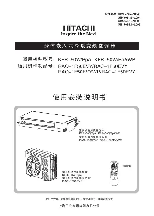
使用产品前,请仔细阅读本使用、安装说明书,并请妥善保管使用安装说明书KFR-50W/BpA KFR-50W/BpAWP 适用机种型号:适用机种制品号:HITACHIRAQ-1F50EVY/RAQ-1F50EVYWP/RAC-1F50EVYRAC-1F50EVY执行标准:GB/T7725-2004GB4706.32-2004GB4343.1-2009GB17625.1-2003使用说明目 录注意事项......................................................................................................................................1产品主要技术参数........................................................................................................................3.....................................................................................................................................................9.....................................................................................................................................................10.....................................................................................................................................................11一键清洁功能.............................................................................................................................................11.....................................................................................................................................................12遥控器电池的更换法.................................................................................................................................12.............................................................................................................................13.....................................................................................................................................14故障查找......................................................................................................................................2机组介绍.....................................................................................................................................................4接收器指示说明.........................................................................................................................................4室内机部品名称.........................................................................................................................................5运转之前.....................................................................................................................................................5遥控器各部分名称和功能.........................................................................................................................6自动运转.....................................................................................................................................................8制热运转除湿运转制冷运转送风运转睡眠定时器的设定功能定时器的设定功能自动控制.. (15)安全须知......................................................................................................................................16安装所需的工具及仪器.............................................................................................................................16运输及吊装.................................................................................................................................................17室内机的安装.............................................................................................................................................17排水管的安装.....................................................................................................................................21接收器(显示接受操作系统)的安装.......................................................................................23保护和控制装置室外机的安装 制冷剂管道安装真空排气顺序电线连接试运行...............................................................................................................................................................23............................................................................................................................................24室外机冷凝水处理.....................................................................................................................................25.........................................................................................................................................25.............................................................................................................................................28.....................................................................................................................................................29.........................................................................................................................................................31附图 (32)安装说明图例意义如下注意事项•电源为单相 220V~ 电压如电压低于或高出正常电压10%以上,空调器将不能正常工作甚至烧断保险丝,易损坏空调器,建议配用220V~ 稳压器。

I L G N EINDOOR UNIT/OUTDOOR UNITSPLIT TYPE AIR CONDITIONERTI N U R O O D N I T I N U R O O D T U O S H Instruction manualRAS-DX10HNK /RAC-DX10HNK RAS-DX13HNK /RAC-DX13HNK RAS-DX18HNK /RAC-DX18HNKRAS-DX10HNK RAS-DX13HNKRAC-DX10HNK RAC-DX13HNK RAC-DX18HNKRAS-DX18HNKSleep Right/Left SilentF .Wash To obtain the best performance and ensure years of trouble free usage, please read this instruction manual completely.請詳細閱讀這本使用說明書以了解正確使用方法,及使機器可長期地發揮最高性能。
PRECAUTIONS DURING SHIFTING OR MAINTENANCEW A R N I N G Should abnormal situation arises (like burning smell), please stop operatingthe unit and turn off the circuit breaker. Contact your agent. Fault, shortcircuit or fire may occur if you continue operating the unit under abnormalsituation.Please contact your agent for maintenance. Improper self maintenance may cause electric shock and fire.Please contact your agent if you need to remove and reinstall the unit.Electric shock or fire may occur if you remove and reinstall the unit by yourself improperly.PRECAUTIONS DURING OPERATIONW A R N I N GFor the sake of health, avoid facing to direct airflow for a long period of time.Do not use any conductor as fuse wire, this could cause fatal accident.During thunderstorm, disconnect and turn off the circuit breaker.If the supply cord is damaged, it must be replaced by the manufacturer,qualified persons in order to avoid a hazardits service agent or SAFETY PRECAUTIONPlease read the “Safety Precaution” carefully before operating the unit to ensure correct usage of the unit.Pay special attention to signs of“ Warning” and “ Caution”. The “Warning” section contains matters which,if not observed strictly, may cause death or serious injury. The “Caution” section contains matters which may resultin serious consequences if not observed properly. Please follow all instructions strictly to ensure safety.The signs indicate the following meanings.Make sure to connect earth line. The sign in the figure indicates prohibition.Indicates the instructions that must be followed.Please keep this manual after reading.PRECAUTIONS DURING INSTALLATIONWARNING Do not reconstruct the unit.Water leakage, fault, short circuit or fire may occur if you reconstruct the unitby yourself.Please ask your sales agent or qualified technician for the installation of your unit. Water leakage, short circuit or fire may occur if you install the unit by yourself.Please use earth line.Do not place the earth line near water or gas pipes, lightning-conductor, orthe earth line of telephone. Improper installation of earth line may causeelectric shock.CAUTIONA circuit breaker should be installed depending on the mounting site of theunit. Without a circuit breaker, the danger of electric shock occurs.Do not install in the location nearby or with flammable gas. The outdoor unit may catch fire if flammable gas leaks around it.Please ensure smooth water flow when installing the drain hose.Do not put your fingers or rods into the air outlet or suction port.If the fans of indoor and outdoor units are running at high speed, which may cause injury or malfunction.PRECAUTIONS DURING OPERATIONW A R N I N GThe product shall be operated under the manufacturer specification and notfor any other intended use.•Do not attempt to operate the unit with wet hands, this could cause fatal accident.•When operating the unit with burning equipments, regularly ventilatethe room to avoid insufficiency of oxygen.•Do not direct the cool air coming out from the air-conditioner panel to facehousehold heating apparatus as this may affect the working of apparatus such asthe electric kettle, oven etc.•Please ensure that outdoor mounting frame is always stable, firm andwithout defect. If not, the outdoor unit may collapse and cause danger.•Do not splash or pour water to the body of the unit when cleaning as this maycause short circuit.•Do not use any aerosol or hair sprays nearby the indoor unit. The chemicalcan adhere on heat exchanger fin and block the evaporation water flowing todrain pan. The water will drop on tangential fan and cause water splashing outfrom indoor unit.•Please switch off the unit and turn off the circuit breaker during cleaning, the high-speed fan inside the unit may cause danger.•Turn off the circuit breaker if the unit is not to be operated for a long period.•Do not climb on the outdoor unit or put objects on it.•Do not put water container (like vase) on the indoor unit to avoid waterdripping into the unit. Dripping water will damage the insulator inside the unitand cause short circuit.•Do not place plants directly under the air flow as it is bad for the plants.•••This appliance is not intended for use by young children or infirm persons unless they have beenYoung children should be supervised to ensure that they do not play with the appliance.adequately supervised by a responsible person to ensure that they can use this appliance safely.••This appliance is not to be used by children or persons with reduced physical, sensory ormental capabilities, or lack of experience and knowledge, unless they have been givensupervision or instruction. Children must be supervised not to play with the appliance.•When operating the unit with the door and windows opened, (the room humidity is always above80%) and with the air deflector facing down or moving automatically for a long period of time,waterwill condense on the air deflector and drip down occasionally. This will wet your furniture.Therefore,do not operate under such condition for a long time.If the amount of heat in the room is above the cooling or heating capability of the unit (for example:more people entering the room, using heating equipments and etc.), the preset room temperaturecannot be achieved.ENGLISHNAMES AND FUNCTIONS OF EACH PARTINDOOR UNIT OUTDOOR UNITAIR FILTERTo prevent dust from coming into the indoor unit. (Refer page 23)Sleep Right/Left Silent F .Wash RAS-DX10HNK RAS-DX13HNK RAS-DX18HNK780792280420215299RAC-DX10HNK/RAC-DX13HNK/RAC-DX18HNK RAS-DX10HNK/RAS-DX13HNK 1050290220RAS-DX18HNK CAUTIONTurn off the circuit breaker or pull outthe power plug if the unit is not beoperated for a long period.INDOOR UNIT INDICATORSLight indicators showing the operating condition.(Refer page 5)FRONT PANEL(Refer page 5)HORIZONTAL DEFLECTOR • VERTICALDEFLECTOR (AIR OUTLET)(Refer page 18)REMOTE CONTROLSend out operation signal to the indoor unit so as tooperate the whole unit.(Refer page 7)Condensed water will drain to outside.C ONNECTION CORDATTACHING AND REMOVING FRONT PANELRECEIVABLE INDICATOR FUNCTIONSOPERATION INDICATORTEMPORARY SWITCHWhen the remote control device is not functioning, use the t emporary s witch mode .(1)When the Temporary Switch is pressed, the unit will operate as per the previous setting. After the power source is turne d off and turn on again, the operation is done in automatic mode.(2)Press the Temporary Switch again will stop the operation of the air conditioner.TEMPORARY SWITCHOPERATION LAMP (Yellow)This lamp lights during operation.FROST WASH LAMP (Green)TEMPORARY SWITCHTIMER LAMP (Orange)This lamp lights when the timer is working.RAS-DX10HNKRAS-DX13HNK RAS-DX18HNKEN G L I S H While gripping both the left and right edges [recessed in the front ] of the front panel, lift up to open the front panel.After completion, slightly lift up the front panel and pull down to close the front panel. Ensure that the 3 sets of left, centre and right clips are fully secured.••AUTO RESTART FUNCTIONPerforms heating operation when the room temperature is below 23°C.Set the temperature to be around 23°C.Performs dehumidifying operation when the room temperature is 23~27°C.The preset temperature will be the room temperature at the start time of air conditioner operation.Performs cooling operation when the room temperature is above 27°C.Set the temperature to be around 27°C.The auto restart feature prompts the air-conditioner to restart in its previous setting right after the power failure. In case of the power failure during the use of timer mode (Sleep Timer or ON/OFF Timer), timer mode is cancelled and the air conditioner stops.Please reset the remote control to restart the unit after the power has been restored.AUTOMATIC OPERATIONHeating Dehumidifying Cooling Air Filter Claw Filter FrameC-caseAir purifying filterAttaching the air purifying filters (Accessories) to the filter frame.•Attach the air purifying filters to the designated position.•The cooling capacity is slightly weakened and the cooling speed becomes slower when the air purifying filters are used.•The air purifying filters are not washable. It is recommended to use vacuum cleaner to clean. It can be used for 1 year. When you want to replace it, please ask your sales agent.HOW TO REPLACE THE BATTERIES IN THE REMOTE CONTROL12Remove the cover as shown in the fi gure and take outthe old batteries.Push and pull to thedirection of arrowInstall the new batteries.The direction of the batteries should match the marksin the case.1.Do not mix the new and old batteries, or use differentkinds of batteries together.2.Take out the batteries when you do not use the remotecontrol for 2 or 3 months.CAUTIONAir purifying filterF-coverRAS-DX10HNKRAS-DX13HNK RAS-DX18HNKEN G L I S H NAMES AND FUNCTIONS OF REMOTE CONTROLThis controls the operation function and timer setting of the room air conditioner. The applicable range of control is about 7 meters. lf indoor lighting is controlled electronically, the range of control may be shorter.Precautions for Use•Do not put the remote control under direct sunlight or high temperature.•Do not drop it on the fl o or, and prevent from water.•If you press the MODE selector button during operation, the compressor may stop for about 3 minutes for protection before you can start it again.Signal Transmission(DEHUMIDIFY) (COOL) and cyclically.( Page 8)ECO Button Use this button to set theECO mode.( Page 17)TIMER OFF Button Select the Timer OFF.( Page 12)TIMER ON Button Select the Timer ON .( Page 12)SLEEP TIMER Button Use this button to set the sleep timer. ( Page 19)POWERFUL Button Press this button to start powerful operation.( Page 13)Transmission Sign The transmission sign blinks when a signal has been sent .ON/OFF ButtonPress this button to startoperation.Press it again to stop operation. TEMPERATURE ButtonRoom temperature setting.Value will change quicker whenkeep pressing.FAN SPEED ButtonSelect the fan speed for coolingmode.UP/DOWN (Horizontal) Button Control the angle of the horizontal air deflector. ( Page 18)RIGHT/LEFT (Vertical) ButtonControls the angle of the vertical air deflector.( Page 18)SILENT ButtonUse this button to set the SILENT mode.( Page 20)FROST WASH Button( Page 14)Sleep Right/Left Silent F .Wash MODE selector Button Use this button to select the operating mode. Every time you press this button, themode will change from (AUTO)(HEAT)(FAN)AUTOMATIC OPERATIONThe device will automatically determine the mode of operation, HEAT or COOL depending on the current room temperature. The selected mode of operation will change when the room temperature varies.-8 -HEATING OPERATIONDefrosting will be performed about once an hour when frost forms on the heat exchange of the outdoor unit , it takes about 5-10 minutes of each cycle.During defrosting operation, the operation lamp blinks in cycle of 2 seconds on and 1 second off. The maximum time for defrosting is 20 minutes.(If the piping length used is longer than usual, frost will likely to form.)●Use the unit for heating when the outdoor temperature is under 27°C.When it is too warm (over 27°C), the heating function may not work in order to protect the unit .●In order to keep reliability of the unit , please use this device above –2°C of the outdoor temperature.-9 -EN G L I S HDEHUMIDIFYING OPERATION■Dehumidifying FunctionUse the unit for dehumidifying when the room temperature is over 16°C.When it is under 15°C, the dehumidifying function will not work.● When the room temperature is higher than the temperature setting: The unit will dehumidify the room,reducing the room temperature to the preset level.When the room temperature is lower than the temperature setting: Dehumidifying will be performed at the temperature setting slightly lower than the current room temperature, regardless of the temperature setting.●The preset room temperature may not be reached depending on the number of people present in the roomor other room conditions.Set the desired room temperature with the ROOMTEMPERATURE setting button (the display indicates the setting).The range of 20°C to 26°C is recommended asthe room temperature for dehumidifying.Temperature range can be set between 16°C and32°C.Press the (ON/OFF) button. Dehumidifying operationstarts with a beep. Press the button again to stop operation.■As the settings are stored in the memory of the remote control, youonly have to press the (ON/OFF) button next time.START STOP Press the MODE selector button so that the displayindicates (DEHUMIDIFY).The fan speed is set at LOW.Press (FAN SPEED) button to select SILENT or LOW fanspeed.12Sleep Right/LeftSilent F .Wash Sleep Right/LeftSilentF .WashEN G L I S H COOLING OPERATIONPress the MODE selector button so that the display indicates(COOL).■As the settings are stored in memory in the remote control, you only have to press the (ON/OFF) button next time.123Set the desired FAN SPEED with the (FAN SPEED) button (thedisplay indicates the setting).START STOP ■During AUTO fan, the fan speed automatically changes as below:●When the difference between room temperature and setting tem-perature is large, fan starts to run at HI speed.●After room temperature reaches the preset temperature, fan speedwill be changed to lower speed to obtain optimum room temperaturecondition for natural healthy airflow .(AUTO) (HIGH) (MED)(SILENT) (LOW)Set the desired room temperature with the TEMPERATURE button(the display indicates the setting).The temperature setting and the actual room temperature may varyd epending on conditions.Temperature range can be set between 16°C and 32°C.Press the (ON/OFF) button. Cooling operation starts with abeep. Press the button again to stop operation. The cooling functiondoes not start if the temperature setting is higher than the currentroom temperature (even though the (OPERATION) lamp lights).The cooling function will start as soon as you set the temperaturebelow the current room temperature.Use the unit for cooling when the outdoor temperature is 7 to 43°C.If indoor humidity is very high (over 80%), some dew may form on the air outlet grille of the indoor unit.Sleep Right/LeftSilent F .Wash Sleep Right/Left Silent F .WashFAN OPERATIONUser can use the unit simply as an air circulator.START STOP 12Press the MODE selector button so that the display indicates(FAN).Press the (ON/OFF) button. Fan operation starts with a beep.Press the button again to stop operation.Press the (FAN SPEED) button.(HIGH) (MED) (LOW) (SILENT)Timer ReservationOFF TIME setting•Select the OFF TIME by pressing the Button.•Setting time will change according to the below sequence when you press the button.1 hour intervalTIMER RESERVATIONON Timer and OFF Timer are available.21 ON TIME setting •Select the ON TIME by pressing the Button.•Setting time will change according to the below sequence when you press the button.Timer off1 hour intervalTimer on Operation stop at setting time .Operation will start for settingtemperature at setting time.Sleep Right/LeftSilentF .Wash Right/LeftF .Wash Right/LeftF .WashSTART●The dust and dirt adhering to indoor heat exchanger is the cause of the smell. They are washed away by freezing and thawing of the heat exchanger.●●Indoor Frost Wash function can work when the outdoor temperature is 1℃ to 43℃ and indoor humidity is 30%to 70%. There are two kinds of Indoor Frost Wash operation, auto mode and manual mode.INDOOR FROST WASH OPERATION※ It depends on the conditions of the room.The process of Indoor Frost WashAbout 8 min About 20 min to 90 min.Operation such as cooling operation Freezing and thawing heat exchanger Auto StopRunning Stop The deflectors remain opened duringfan operation, freezing, thawing.●If you want to stop Indoor Frost Wash operation, press the (ON/OFF ) button twice.● lamp on the indoor unit lights up during Indoor Frost Wash operation.Indoor Frost Wash starts Indoor Frost Wash ends●When pressing the button such as cooling during Indoor Frost Wash operation, Indoor Frost Wash operation is discontinued and start the cooling operation after about 3 minutes.●When Indoor Frost Wash is stopped during Indoor Frost Wash operation, the unit automatically restart Indoor Frost Wash operation when the next operation stops.●In order to protect the unit , Indoor Frost Wash function cannot be carried out again for about 60 minutes after Indoor Frost Wash operation is completed." "Fan operation ■ Indoor Frost Wash (Auto mode)Indoor Frost Wash auto start conditions●When the outdoor temperature or indoor humidity are not suitable for Indoor Frost Wash operation, only fan operation is carried out, Indoor Frost Wash operation will be done again after the next operation stops.●Sometimes the heat exchanger may not freeze depending on the conditions of the room.●When the ON timer reaches the set time during Indoor Frost Wash operation, it will stop the Indoor Frost Wash operation and start the operation of setting mode.●If the interval of the Off to On timer is less than 2 hours, Indoor Frost Wash operation may not be completed. In that case, it will restart Indoor Frost Wash operation after the next operation stops.Once the auto mode of Indoor Frost Wash operation interval (42 hours) is reached, stop operating the air conditioner and activate Indoor Frost Wash in Auto or Manual mode.Accumulated operating hours of the air conditioner have exceeded 42 hoursAir conditioner is stopped operating for more than 30 minutes, such as coolingoperation Indoor Frost Wash startIndoor Frost Wash end About 20 min to 90 min.About 30 minutes or more Operation such as cooling operation Operation such ascooling operation Last Indoor Frost Wash Running Stop Running StopAuto StopIndoor Frost Wash Accumulated operating hours of the air conditionerhave exceeded 42 hoursFROST WASH OPERATION-15 -EN G L I SH Precautions for Use● Hissing, fizzy or squeaking noise may generate during Indoor Frost Wash operation.●After turning on the power, please wait a moment if you want to start Indoor Frost Wash.Upon completion of Indoor Frost Wash with manual mode, operation interval (42 hours) of Indoor Frost Wash with auto mode will be re-calculated.● ●Do not open windows or doors during Indoor Frost Wash operation. Water will condense on the air deflector and drips down occasionally. This will wet your furniture.●Do not open or remove the front panel during Indoor Frost Wash operation. It may cause injury or malfunction.●Indoor Frost Wash operation does not wash away all dust and dirt.●If the air conditioner is continuously running, Indoor Frost Wash function is not effective.●During Indoor Frost Wash operation, if power is turned off and then power is restored, Indoor Frost Wash function will not restart.-16 -STARTCANCELIn case the power consumption is already low,AUTO SWING OPERATIONVERTICAL SWING■To start Vertical Auto Swing■To cancel Horizontal Auto Swing●Press (UP/Down (HORIZONTAL)) button. The deflectors willis displayed on the LCD.●Press (Right/L eft (VERTICAL )) button. The defl ectors willstart to swing right and left.is displayed on the LCD.●Press (UP/Down (HORIZONTAL )) button again. The deflectorswill stop at the current position.disappeared from the LCD.●Press (Right/Left (VERTICAL)) button again. The defl ectorswill stop in the current position.disappeared from the LCD.NOTEstart to swing up and down.Sleep Right/LeftF .Wash Silent Sleep Right/Left F .Wash SilentHORIZONTAL SWING■To start Horizontal Auto Swing■To cancel Vertical Auto Swing●●During cooling and dehumidifying operation, do not keep the de fl ectors swinging or in the lower position (in the case of vertical auto swing) for a long time. It may cause dew condensation on the de fl ectors.To avoid accidents, do not adjust deflectors with your hands.EN G L I S H SLEEP TIMER OPERATIONThe timer can be set up to a duration of 7 hours.By pressing (SLEEP) button during AUTO, DEHUMIDIFYING, COOLING or FAN operation, the unit shifts the room temperature and reduces the fan speed. It results in energy saving.■To start SLEEP TIMER operationPress (SLEEP) button during operation.● “”, “”, “ ” and number of hours are displayedon the remote control display.●During SLEEP TIMER operation, fan speed will be ultra●slow.● A beep sound emitted from indoor unit and the TIMER lampon the indoor unit lights up.Pressing (SLEEP) button repeatedly, the number of hourswill change as below:●During SL EEP TIMER operation, air conditioner willcontinue operating for the designated number of hours andthen turn off.■To cancel SLEEP TIMER operation■Press (On/Off) button.●Air conditioner will switch off.Press (SLEEP) button again until “”, “”,“ ” and number of hours disappear from the remotecontrol display.1 1 H2 H3 H 7 HSLEEP TIMER offSleep Sleep Sleep SleepSleep Sleep Right/Left F .Wash SilentSILENT OPERATION●By pressing (SIL ENT) button during DEHUMIDIFYING, COOL ING or FAN operation, the fan speed will change to ultra slow.■To start SILENT operation■To cancel SILENT operation●Press (SILENT) button during operation.“ ” is displayed on the LCD. Fan speed will be ultra slow.●Press (On/Off) button.●Press (SIL ENT) button again or (FAN SPEED)button.Fan speed will return to previous fan speed before SIL ENToperation starts.SILENT operation stops , “ ” disappears from the LCD.1SilentSilentSilentSleep Right/Left F .Wash Silent NOTE●●When POWERFUL operation is selected, SILENT operation is cancelled. Fan speed wil l return to previous fan speed before SILENT operation.After auto restart, SILENT operation is cancelled. Fan speed will return to previous fan speed before SILENT operation." (SLIENT), fan speed will not change even if p ressing ●If the operation is running with fan speed " " " (SLIENT) button.THE IDEAL WAYS OF OPERATIONSuitable Room TemperatureWarningFreezing temperatureis bad for health and awaste of electric power.Install curtain or blindsI t i s p o s s i bl eto reduce heatentering the roomthrough windows.VentilationCautionDo not close the room for a long period of time. Occasionally open the door and windows to allow theentrance offresh air.Effective Usage Of Timer At night, please use the " sleep timer " mode, together with your wake up time in the morning. This will enable you to enjoy a comfortable room temperature. Please use the timer effectively.Do Not Forget T o Clean The Air Filter Dusty air filter will reduce the air volume and the cooling efficiency. To prevent from wasting electric energy, please clean the filter every 2 weeks.TemperaturenPlease Adjust Suitable TemperatureFor Baby And ChildrenPlease pay attention to the room temperatureand air flow direction when operating the unitfor baby, children and old folks who havedifficulty in movement.(The ideal temperaturedifference betweenoutdoor and indooris about f5°C).ENGLISHFOR USER’S INFORMATIONThe Air Conditioner And The Heat Source In The Room CautionIf the amount of heat in the room is above thecooling capability of the air conditioner (for example:more people entering the room, using heatingequipments and etc.), the preset room temperaturecannot be achieved.Not Operating For A Long TimeWhen the indoor unit is not to be used for a longperiod of time, please pull out the power plug. Or theindoor unit still consumes about 1W in the operationcontrol circuit even if it is in “OFF” mode.OFFWhen Lightning OccursWarningTo protect the whole unit during lightning, pleasestop operating the unit and remove the plug from thesocket.Interference From Electrical ProductsCautionTo prevent interference, place at least 1m away.TV Inverter-type fluorescent lamp.To avoid signal interference, please place the indoor unit and its remote control at least 1m away from electrical products.MAINTENANCE OF THE UNITS CAUTIONEnsure that the unit is not in operation and all power supply has been disconnected before cleaning the unit.Dust Filter ScreenDust filter screens are installed to remove the indoor dust particles hence they should be kept clean at all times. They should be cleaned at each machine operation cycle of approximately 100 hours. Excessive dust collected at the dust filter screen will block the air flow, reduce the cooling capability and could produce noise. Therefore the dust filter screen should be cleaned as per instructions given below:Cleaning Instructions(1)Removing the dust filter screen•While holding both edges of the front panel, open up and lift the front panel and push in to park at the secured position.Front panelFront cabinet•Slightly lift up the dust filter screen, release the latch clips [2 places] located at the bottom of the front cabinet and move the dust filter screen downward to remove it from the unit.(2)U se a vacuum cleaner to vacuum clean the dust accumulated at the dust filter screen. If the accumulated dustis too much to be removed by vacuum cleaning, apply mild detergent and flush the dust from the dust filter screen with water. After thorough rinsing, leave the dust filter screen at a cool shaded place to dry.(3)R e-install the dust filter screen to its original position (With “FRONT” marker facing front). Slightly lift up theopened front panel and close it by returning it to its original position.(4)E ach year before using the air conditioner, clean the heat exchanger (evaporator) with a fine soft brush or avacuum cleaner and take care to avoid damaging the evaporator fins.Front panelDust filter screenLatch clipCAUTION•Do not use hot water (40e C or above) to rinse the dust filter screen, otherwise the screen will warp and get distorted. After rinsing, shake the dust filter screen to rid off all remaining water droplets and place it at a cool shaded place to dry. Avoid placing the dust filter screen under direct sunlight, otherwise the screen will warp and get distorted.Do not operate the air conditioner unit without the dust filter screen, otherwise the ingress of dust into the air conditioner unit will cause breakdowns.E N G L I S H。
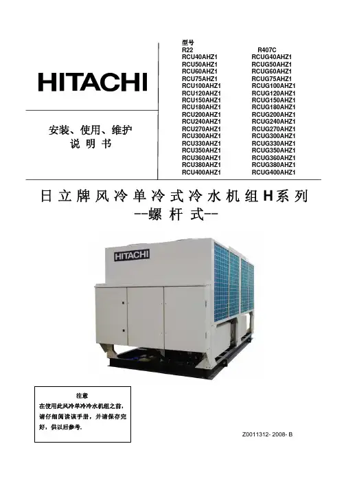
安装、使用、维护说 明 书日立牌风冷单冷式冷水机组H 系列--螺 杆 式--Z0011312- 2008- B型号R22 R407CRCU40AHZ1 RCUG40AHZ1 RCU50AHZ1 RCUG50AHZ1 RCU60AHZ1 RCUG60AHZ1 RCU75AHZ1 RCUG75AHZ1 RCU100AHZ1 RCUG100AHZ1 RCU120AHZ1 RCUG120AHZ1 RCU150AHZ1 RCUG150AHZ1 RCU180AHZ1 RCUG180AHZ1 RCU200AHZ1 RCUG200AHZ1 RCU240AHZ1 RCUG240AHZ1 RCU270AHZ1 RCUG270AHZ1 RCU300AHZ1 RCUG300AHZ1 RCU330AHZ1 RCUG330AHZ1 RCU350AHZ1 RCUG350AHZ1 RCU360AHZ1 RCUG360AHZ1 RCU380AHZ1 RCUG380AHZ1 RCU400AHZ1 RCUG400AHZ1重要通知●日立对产品的设计和性能将不断进行改良,规格如有更改,恕不另行通知。
●日立对每一个可能的情况可引致有潜在的危险不作预测。
●没有书面允许,此说明书不得翻印。
●信号字句(危险,警告和小心)用于鉴别危险性的级别,有关各信号字句所提示的危险性解释 如下:: 可能导致严重个人受伤或死亡的直接危险。
: 危险或不安全的操作可能导致严重个人受伤或死亡。
: 危险或不安全的操作可能导致轻微个人受伤或产品或财物损害。
: 对使用或维修有帮助的资料。
●如有需要,请联络您所聘用之承建商或日立分销商。
●此说明书提供其他型号的风冷单冷式冷水机组的共同描述和资料。
●此风冷单冷式冷水机组是根据以下温度设计,冷水机组应在此范围使用:工作范围● 此说明书为风冷单冷式冷水机组的永久部件,应保留在冷水机组内。
● 下表为本说明书中所叙机组的能效等级汇总:机型能效 等级 机型能效等级机型 能效 等级机型 能效 等级RCU40AHZ1 4 RCU200AHZ1 3 RCUG40AHZ1 5 RCUG200AHZ14 RCU50AHZ1 3 RCU240AHZ1 3 RCUG50AHZ15 RCUG240AHZ1 4 RCU60AHZ1 3 RCU270AHZ1 3 RCUG60AHZ1 4 RCUG270AHZ1 4 RCU75AHZ1 3 RCU300AHZ1 3 RCUG75AHZ1 4 RCUG300AHZ1 4 RCU100AHZ1 3 RCU330AHZ1 3 RCUG100AHZ1 5 RCUG330AHZ1 4 RCU120AHZ1 3 RCU350AHZ1 3 RCUG120AHZ1 4 RCUG350AHZ1 4 RCU150AHZ1 3 RCU360AHZ1 3 RCUG150AHZ1 4 RCUG360AHZ1 4 RCU160AHZ1 3 RCU380AHZ1 3 RCUG160AHZ1 5 RCUG380AHZ1 4 RCU180AHZ1 3RCU400AHZ1 3 RCUG180AHZ1 4 RCUG400AHZ14*依据国家标准:GB19577-2004 作为能效等级判定。
MODELRAS-25YHA / RAC-25YHARAS-35YHA / RAC-35YHAInstruction manualTo obtain the best performance and ensure years oftrouble free use, please read this instruction manualcompletely.INDOOR UNIT/OUTDOOR UNIT– 2 –• Please read the “Safety Precaution” carefully before operating the unit to ensure correct usage of the unit.• Pay special attention to signs of “ Warning ” and “ Caution ”. The “Warning” section contains matters which, if not observed strictly, may cause death or serious injury. The “Caution” section contains matters which may result in serious consequences if not observed properly. Please observe all instructions strictly to ensure safety.• • Please keep this manual after reading.– 3 –– 4 –NAMES AND FUNCTIONS OF EACH PARTMODEL NAME AND DIMENSIONSAir filterTo prevent dust from coming into the indoor unit.(Refer page 16)Front panelIndoor unit indicatorsLight indicator showing the operating condition.(Refer page 5)Horizontal deflector Vertical deflector (Air Outlet)(Refer page 15)Remote controllerSend out operation signal to the indoor unit. So as to operate the whole unit.(Refer page 6)About the outdoor unit:• When “Stop” is selected during operation of the indoor unit, the fan of the outdoor unit continuesturning for 10 to 60 seconds to cool the electric parts down.• In heating operation, condensate or water due to defrosting will flow. Do not cover the drain port of the outdoor unit because such water may freeze in the chilly area.• When the outdoor unit is hung on the ceiling, instal the bush and drain pipe on the drain port and drain-water.– 5 –NAMES AND FUNCTIONS OF EACH PART FILTER LAMP (Green)When the device is operated for a total of about 200 hours, the FILTER lamp lights indicates that it isto clean the filter.The lamp goes out when the(AUTO SWING)” button is pressed while the OPERATION LAMP (Yellow)This lamp lights during operation.The OPERATION LAMP flashes in the following cases during heating.(1) DURING PREHEATINGFor about 2-3 minutes after starting up.(2) DURING DEFROSTINGDefrosting will be performed about oncean hour when frost forms on the heat exchanger of the outdoor unit, for 5-10 minutes each time.Use this switch to start and stop when the remote controller does not work.This temporary operation will be at the most recent setting made. (The unit will immediately go into automatic operation once power is switched on. The power is saved by turning off the power switch (or the circuit breaker when the power is supplied from the outdoor unit).Attaching the air cleansing and deodorizing filters (Accessories) to the filter frame.• Attach the air cleansing and deodorizing filters to the frame by gently compress its both sides and release after insertion into filter frame.• The cooling capacity is slightly weakened and the cooling speed becomes slower when the air cleansing and deodorizing filters are used.• Air cleansing and deodorizing filters can be used for about 1 year. When you want to renew it, please ask your sales agent.Attaching the negative ion stick to the filter frameto push up the upper hooks.Lower hookNAMES AND FUNCTIONS OF EACH PARTREMOTE CONTROLLER• This controls the operation of the indoor unit. The range of control is about 7 meters. If indoor lighting is controlled electronically, the range of control may be shorter.This unit can be fixed on a wall using the fixture provided. Before fixing it, make sure the indoor unit can be con-trolled from the remote controller.• Handle the remote controller with care. Dropping it or getting it wet may compromise its signal transmission ca-pability.• After new batteries are inserted into the remote controller, the unit will initially require approximately 10 seconds to respond to commands and operate.– 6 –– 7 –VARIOUS FUNCTIONSAUTOMATIC OPERATIONThe device will automatically determine the mode of operation, HEAT or COOL depending on the initial room temperature. The selected mode of operation will change when the room temperaturevaries varies.• If there is a power failure, operation will be automatically restarted when the power is resumed with previous operation mode and airflow direction.(As the operation is not stopped by remote controller.)• If you intend not to continue the operation when the power is resumed, switch off the power supply.When you switch on the circuit breaker, the operation will be automatically restarted with previous operation mode and airflow direction.Note: 1. If you do not require Auto Restart Control, please consult your sales agent. 2. Auto Restart Control is not available when Timer or Sleep Timer mode is set.HEATING OPERATION• Use the device for heating when the outdoor temperature is under 21°C.When it is too warm (over 21°C), the heating function may not work in order to protect the device.• In order to keep reliability of the device, please use this device above -10°C of the outdoor temperature.– 8 –– 9 –DEHUMIDIFYING OPERATION• Dehumidifying takes place with a target temperature which is slightly lower than the room temperature setting. (However, target temperature is 16°C for a temperature setting of 16°C.)If the room temperature becomes lower than the target value, operation stops. If the room temperature be-comes higher than the target value, operation restarts.• The preset room temperature may not be reached depending on the number of people present in the room or other room conditions.COOLING OPERATION– 10–– 11–FAN OPERATIONFAN SPEED (AUTO)– 12–HOW TO SET THE TIMER– 13–• The timer may be used in three ways: off-timer, on-timer and ON/OFF (OFF/ON)-timer. Set the current time at first because it serves as a reference.• button is order to use the same settings next time.– 14–– 15–HOW TO EXCHANGE THE BATTERIES IN THE REMOTE CONTROLLERPush and pull to the direction of arrow.the blade is marked.the blade is marked.MAINTENANCE– 16–– 17–– 18–INFORMATIONREGULAR INSPECTIONPLEASE CHECK THE FOLLOWING POINTS EVERY EITHER HALF YEARL Y OR YEARL Y . CONTACT YOUR SALES AGENT SHOULD YOU NEED ANY HELP .CONDITIONCHECK THE FOLLOWING POINTS• Do the batteries need replacement?• Is the polarity of the inserted batteries correct?• Is the air filter blocked with dust?• Is the set temperature suitable?• Have the top and bottom air deflectors been adjusted to their correct positions according to the operation mode selected?• Are the air inlets or air outlets of indoor and outdoor units blocked?• Is the fan speed “LOW”?AFTER SALES SERVICE AND WARRANTY• Is the fuse all right?• Is the voltage extremely high or low?• Is the circuit breaker “ON”?• Is the power plug inserted?• Do you have any power cut?When it does not operate.When it does not cool well.When it does not heat well.– The following phenomena do not indicate unit failure.If the remote controller is not transmitting a signal.(Remote controller display is dim or blank.)– 20–• If the unit still fails to operate normally after performing the above inspections, turn the circuit breaker off and contact your sales agent im-mediately.• Please contact your sales agent immediately if the air conditioner still fails to operate normally after the above inspections. Inform your agent of the model of your unit, production number, date of installation. Please also inform him regarding the fault.Please note:On switching on the equipment, particularly when the room light is dimmed, a slight brightness fluctuation may occur. This is of no consequence.The conditions of the local Power Supply Companies are to be observed.。
EEDDE08-204 technical dataWall Mounted Unit FXAQ-MAVE air conditioning systems2eTABLE OF CONTENTSFXAQ-MAVE1Specifications . . . . . . . . . . . . . . . . . . . . . . . . . . . . . . . . . . . . . . . . . . . . . . . . . . . . . . . 2Technical Specifications . . . . . . . . . . . . . . . . . . . . . . . . . . . . . . . . . . . . . . . . . . . . . 2Electrical Specifications . . . . . . . . . . . . . . . . . . . . . . . . . . . . . . . . . . . . . . . . . . . . . 32Safety device settings . . . . . . . . . . . . . . . . . . . . . . . . . . . . . . . . . . . . . . . . . . . . . 43Options . . . . . . . . . . . . . . . . . . . . . . . . . . . . . . . . . . . . . . . . . . . . . . . . . . . . . . . . . . . . . . 44Control systems . . . . . . . . . . . . . . . . . . . . . . . . . . . . . . . . . . . . . . . . . . . . . . . . . . . . 55Capacity tables . . . . . . . . . . . . . . . . . . . . . . . . . . . . . . . . . . . . . . . . . . . . . . . . . . . . . 6Cooling capacity tables . . . . . . . . . . . . . . . . . . . . . . . . . . . . . . . . . . . . . . . . . . . . . . 6Heating capacity tables . . . . . . . . . . . . . . . . . . . . . . . . . . . . . . . . . . . . . . . . . . . . . . 86Dimensional drawing & centre of gravity . . . . . . . . . . . . . . . . . . . . . . . 10Dimensional drawing . . . . . . . . . . . . . . . . . . . . . . . . . . . . . . . . . . . . . . . . . . . . . . . . 107Piping diagram. . . . . . . . . . . . . . . . . . . . . . . . . . . . . . . . . . . . . . . . . . . . . . . . . . . . . 128Wiring diagram. . . . . . . . . . . . . . . . . . . . . . . . . . . . . . . . . . . . . . . . . . . . . . . . . . . . . 13Wiring diagram . . . . . . . . . . . . . . . . . . . . . . . . . . . . . . . . . . . . . . . . . . . . . . . . . . . . . . 139Sound data. . . . . . . . . . . . . . . . . . . . . . . . . . . . . . . . . . . . . . . . . . . . . . . . . . . . . . . . . 14Sound pressure spectrum . . . . . . . . . . . . . . . . . . . . . . . . . . . . . . . . . . . . . . . . . . . 1410Installation. . . . . . . . . . . . . . . . . . . . . . . . . . . . . . . . . . . . . . . . . . . . . . . . . . . . . . . . . . 16Service space . . . . . . . . . . . . . . . . . . . . . . . . . . . . . . . . . . . . . . . . . . . . . . . . . . . . . . . 16•VRV® Systems • Indoor Units11-1 TECHNICAL SPECIFICATIONS FXAQ20MAVE FXAQ25MAVE FXAQ32MAVE FXAQ40MAVE FXAQ50MAVE FXAQ63MAVENominal Capacity Cooling kW 2.20 2.80 3.60 4.50 5.607.10 Heating kW 2.50 3.20 4.00 5.00 6.308.00Power input (Nominal)Cooling kW0.0160.0220.0270.0200.0270.050 Heating kW0.0240.0270.0320.0200.0320.060Casing Colour white (3.0Y8.5/0.5)Dimensions Unit Height mm290290290290290290 Width mm795795795105010501050Depth mm230230230230230230 Weight Unit kg111111141414Heat Exchanger Dimensions Nr of Rows222222 Fin Pitch mm 1.40 1.40 1.40 1.40 1.40 1.40FaceAream²0.1610.1610.1610.2130.2130.213 Nr of Stages141414141414Fan Type Cross flow fanQuantity1111Air Flow Rate Cooling High m³/min7.508.009.0012.0015.0019.00 Low m³/min 4.50 5.00 5.509.0012.0014.00 Fan Motor Quantity111111 Model QCL9661M QCL9661M QCL9661M QCL9686M QCL9686M QCL9686MOutput(high)W404040434343 Drive Direct driveRefrigerant Name R-410ACooling SoundPressure High dBA35.036.037.039.042.046.0 Low dBA29.029.029.034.036.039.0Piping connections Liquid (OD)Type Flare connectionDiameter mm 6.4 6.4 6.4 6.4 6.359.5 Gas Type Flare connectionDiameter mm12.712.712.712.712.715.9 Drain Diameter mm181818181818 Heat Insulation Foamed polystyrene/polyethyleneAir Filter Washable resin net Refrigerant control Electronic expansion valve Temperature control Microprocessor thermostat for cooling and heating Safety devices PC board fuseStandard Accessories Standard Accessories Installation and operation manualInstallation panelPaper pattern for installationInsulation tapeClampsScrewsNotes Nominal cooling capacities are based on : indoor temperature : 27°CDB, 19°CWB, outdoor temperature : 35°CDB,equivalent refrigerant piping : 5m (horizontal)Nominal heating capacities are based on : indoor temperature : 20°CDB, outdoor temperature : 7°CDB, 6°CWB,equivalent refrigerant piping : 5m (horizontal)Capacities are net, including a deduction for cooling (an addition for heating) for indoor fan motor heat.•VRV® Systems • Indoor Units21-2 ELECTRICAL SPECIFICATIONS FXAQ20MAVE FXAQ25MAVE FXAQ32MAVE FXAQ40MAVE FXAQ50MAVE FXAQ63MAVEPower Supply Name VEPhase111111Frequency Hz505050505050Voltage V220-240A0.300.400.400.400.400.60Current Minimum circuit amps(MCA)Maximum fuse amps (MFA)A15.0015.0015.0015.0015.0015.00Full load amps (FLA)A0.200.300.300.300.300.50Voltage range Minimum V-10%Maximum V+10%Notes Voltage range : units are suitable for use on electrical systems where voltage supplied to unit terminals is not belowor above listed range limits.Maximum allowable voltage range variation between phases is 2%.MCA/MFA : MCA = 1.25 x FLAMFA<= 4 x FLAnext lower standard fuse rating minimum 15Aselect wire size based on the MCAinstead of a fuse, use a circuit breakerFor more details concerning conditional connections, see , select "E-Data Books”.Finally, click on the document title of your choice.•VRV® Systems • Indoor Units32Safety device settings3Options4•VRV® Systems • Indoor Units4Control systems•VRV® Systems • Indoor Units5•VRV ® Systems • Indoor Units6•VRV® Systems • Indoor Units7•VRV ® Systems • Indoor Units8•VRV® Systems • Indoor Units9•VRV ® Systems • Indoor Units10Approx. 40023223029050 or more (Required space)Dimensions for full open front panelPiping directionPiping direction626795155125Outside lineø 80 holeø 80 hole1076014.544105446298Piping direction50 or more (Required space)120 or less30 o r m o r e (r e q u i r e d s p a c e )90 o r m o r e (r e q u i r e d s p a c e )2500 or more For installation in high places(Filter part)(Filter part)(Flexible tube part)Name plate Note 2Approx. 475Approx. 460Approx. 415Approx. 290(Piping and wiring intake)Mounting locationFXAQ40,50MAApprox. 40023223029050 or more (Required space)Dimensions for full open front panelPiping directionPiping direction8941,050155125Outside lineø 80 holeø 80 hole1046014.544105445298Piping direction50 or more(Required space)120 or less30 o r m o r e (r e q u i r e d s p a c e )90 o r m o r e (r e q u i r e d s p a c e )2,500 or more For installation in high places(Filter part)(Filter part)(Flexible tube part)Name plate Note 2Approx. 475Approx. 460Approx. 415Approx. 290(Piping and wiring intake)Mounting location•VRV ® Systems • Indoor Units11Approx. 40023223050 or more (Required space)Dimensions for full open front panelPiping directionPiping direction8941,050155125Outside lineø 80 holeø 80 hole1046014.544105445298Piping direction50 or more (Required space)120 or less30 o r m o r e (r e q u i r e d s p a c e )90 o r m o r e (r e q u i r e d s p a c e )2,500 or more For installation in high places(Filter part)(Filter part)Name plate Note 2Approx. 475Approx. 460Approx. 415(Piping and wiring intake)Mounting location•VRV ® Systems • Indoor Units12Liquid pipe connection portFilterFilterElectronic expansion valveFanGas pipe connection portRefrigerant flow Cooling HeatingHeat exchangerPiping connection diameters ModelGas Liquid FXAQ20,25,32,40,50MA ø12.7ø6.4FXAQ63MAø15.9ø9.5•VRV ® Systems • Indoor Units138 - 1Wiring diagram220-240V ~50Hz 220V ~60HzPower supply Control Box (Indoor unit)FrontSideReceiver/display unit(Infrared remote control)Note 5Note 5Note 2Note 1Input from outside Transmission wiring Central remote controlWired remote controlNOTES1In case of using central remote control, connect it to the unit in accordance with the attached installation manual.2When connecting the input wires from outside, forced off or on/off control operation can be selected by remote control. In details, refer to the installation manual atached the unit..3Remote control model varies according to the combination system. Confirm engineering data and catalogs, etc.. before connecting.4Confirm the method of setting the selector switch (SS1, SS2) of wired remote control and infrared remote control by installation manual and engineering data, etc.5X24A is connected when the infrared remote control kit is being used.Indoor Unit A1P Printed circuit board Y1E Electronic expansion valve SS1Selector switch (Main/sub)F1U Fuse (Ꭾ , 3A, 250V)PC Power CircuitSS2Selector switch (Wireless adress set)HAP Light emitting diode (Service monitor-green)Receiver/display unit (Attached to infrared remote control)M1F Motor (Indoor fan)A2P Printed circuit board Wired remote control M1S Motor (Swing flap)A3P Printed circuit board R1T Thermistor (Air)R1T Thermistor (Air)BS1Push button (On/off)SS1Selector switch (Main/sub)R2T Thermistor (Coil liquid pipe)H1P Light emitting dide (On-red)R3T Thermistor (Coil gas pipe)H2P Light emitting diode (Timer green)Connector for optional parts X1M Terminal block (Control)H3P Light emitting diode (Filter sign-red)X15A Connector (Float switch)X2MTerminal block (Power)H4P Light emitting diode (Defrost-orange)X35A Connector (Group control adapter)COLORS : BLK : Black PNK : Pink BLU : Blue RED : Red BRN : Brown WHT : White GRN : Green YLW : YellowORG : Orange: Terminal: Connector: Shows short circuit connector : Field wiring,•VRV ® Systems • Indoor Units14(B, G, N is already rectified)Operating conditons:Power source: 220-240V 50Hz / 220V 60HzCooling: Return air temperature: 27 C DB, 19 C WB; Outdoor temperature: 35Heating: Return air temperature: 20 C DB, 15 C WB; Outdoor temperature: 7Measuring place: Anechoic chamber Location of microphoneOperating noise differs with operation and ambient conditions.Ocatve band center frequency (Hz)HILOWApproximate treshold hearing for continuous noiseO c a t v e b a n d s o u n d p r e s s u r e e v e d B (0d B =00002μ b a r )ScaleModeHi Low A 35.029.0C 39.534.5Mike1m 1m(B, G, N is already rectified)Operating conditons:Power source: 220-240V 50Hz / 220V 60HzCooling: Return air temperature: 27 C DB, 19 C WB; Outdoor temperature: 35Heating: Return air temperature: 20 C DB, 15 C WB; Outdoor temperature: 7Measuring place: Anechoic chamber Location of microphoneOperating noise differs with operation and ambient conditions.Ocatve band center frequency (Hz)HILOWApproximate treshold hearing for continuous noiseO c a t v e b a n d s o u n d p r e s s u r e e v e d B (0d B =00002μ b a r )ScaleModeHi LowA 36.029.0C 40.534.0Mike1m 1m(B, G, N is already rectified)Operating conditons:Power source: 220-240V 50Hz / 220V 60HzCooling: Return air temperature: 27 C DB, 19 C WB; Outdoor temperature: 35Heating: Return air temperature: 20 C DB, 15 C WB; Outdoor temperature: 7Measuring place: Anechoic chamber Location of microphoneOperating noise differs with operation and ambient conditions.Ocatve band center frequency (Hz)HILOWApproximate treshold hearing for continuous noiseO c a t v e b a n d s o u n d p r e s s u r e e v e d B (0d B =00002μ b a r )ScaleModeHi Low A 37.029.0C 41.534.5Mike1m 1m(B, G, N is already rectified)Operating conditons:Power source: 220-240V 50Hz / 220V 60HzCooling: Return air temperature: 27 C DB, 19 C WB; Outdoor temperature: 35Heating: Return air temperature: 20 C DB, 15 C WB; Outdoor temperature: 7Measuring place: Anechoic chamber Location of microphoneOperating noise differs with operation and ambient conditions.Ocatve band center frequency (Hz)HILOWApproximate treshold hearing for continuous noiseO c a t v e b a n d s o u n d p r e s s u r e e v e d B (0d B =00002μ b a r )ScaleModeHi LowA 39.034.0C 41.039.0Mike1m 1m•VRV ® Systems • Indoor Units15(B, G, N is already rectified)Operating conditons:Power source: 220-240V 50Hz / 220V 60HzCooling: Return air temperature: 27 C DB, 19 C WB; Outdoor temperature: 35Heating: Return air temperature: 20 C DB, 15 C WB; Outdoor temperature: 7Measuring place: Anechoic chamber Location of microphoneOperating noise differs with operation and ambient conditions.Ocatve band center frequency (Hz)HILOWApproximate treshold hearing for continuous noiseO c a t v e b a n d s o u n d p r e s s u r e e v e d B (0d B =00002μ b a r )ScaleModeHi Low A 42.036.0C 44.039.0Mike 1m 1m(B, G, N is already rectified)Operating conditons:Power source: 220-240V 50Hz / 220V 60HzCooling: Return air temperature: 27 C DB, 19 C WB; Outdoor temperature: 35Heating: Return air temperature: 20 C DB, 15 C WB; Outdoor temperature: 7 Measuring place: Anechoic chamber Location of microphoneOperating noise differs with operation and ambient conditions.Ocatve band center frequency (Hz)HILOWApproximate treshold hearing for continuous noiseO c a t v e b a n d s o u n d p r e s s u r e e v e d B (0d B =00002μ b a r )ScaleModeHi LowA 46.039.0C 48.042.0Mike1m 1m10Installation10 - 1Service space16•VRV® Systems • Indoor Units2eÈEEDEN08-204aËÍDaikin Europe N.V. is approved by LRQA for its Quality Management System in accordance with the ISO9001 standard. ISO9001 pertains to quality assurance regarding design, development,manufacturing as well as to services related to the product.Daikin units comply with the European regulations that guarantee the safety of the product.E E D E N 08-204 • 01/2008 • C o p y r i g h t © D a i k i nT h e p r e s e n t p u b l i c a t i o n s u p e r s e d e s E E D E N 07-200P r e p a r e d i n B e l g i u m b y L a n n o o (w w w .l a n n o o p r i n t .b e ), a c o m p a n y w h o s e c o n c e r n f o r t h e e n v i r o n m o n t i s s e t i n t h e E M A S a n d I S O 14001 s y s t e m s .R e s p o n s i b l e E d i t o r : D a i k i n E u r o p e N .V ., Z a n d v o o r d e s t r a a t 300, B - 8400 O o s t e n d eThe present publication is drawn up by way of information only and does not constitute an offer binding upon Daikin Europe N.V.. Daikin Europe N.V. has compiled the content of this publication to the best of its knowledge. No express or implied warranty is given for the completeness, accuracy, reliability or fitness for particular purpose of its content and the products and services presented therein.Specifications are subject to change without prior notice. Daikin Europe N.V. explicitly rejects any liability for any direct or indirect damage, In the broadest sense, arising from or related to the use and/or interpretation of this publication. All content is copyrighted by Daikin Europe N.V..VRV ® products are not within the scope of the Eurovent certification programme.Naamloze Vennootschap Zandvoordestraat 300B-8400 Oostende, Belgium www.daikin.euBTW: BE 0412 120 336RPR OostendeDaikin’s unique position as a manufacturer of air conditioning equipment, compressors and refrigerants has led to its close involvement in environmental issues. For several years Daikin has had the intension to become a leader in the provision of products that have limited impact on the environment. This challenge demands the eco design and development of a wide range of products and an energy management system, resulting in energy conservation and a reduction of waste.ISO14001 assures an effective environmental management system in order to help protect human health and the environment from the potential impact of our activities, products and services and to assist in maintaining and improving the quality of the environment.。
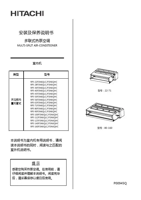
安装及保养说明书室内机本说明书为室内机专用说明书,请阅读本说明书的同时,阅读与之匹配的室外机说明书。
提 示感谢您购买热泵空调。
在使用前,请仔细阅读并理解本说明书。
阅读完毕后,请妥善保存以便日后使用。
多联式热泵空调MULTI-SPLIT AIR-CONDITIONER型号:22-71型号:80-160P00945Q尊敬的用户:您好!感谢您选择和使用本公司产品。
为了您更好的了解和使用本产品,在使用之前,务必阅读并遵守以下相关事项。
本说明书应被视为空调设备的一部分,请妥善保管。
本说明书对热泵式空调机进行了统一的说明及介绍,因此,既可用于您的空调机也适用于其它空调。
本公司致力于不断地对产品进行改进,如有变更恕不另行通知。
本公司对于空调机因在特定环境中运转而发生的偶然性损坏事故,不负任何责任。
本空调只能作为普通空调使用,不能用于干燥服装、冷冻食品、冷却或加热等其他目的。
请勿将空调安装在以下场合。
否则可能导致火灾、机器变形或者故障。
*有油飞溅的地方(包括机油)。
有易燃气体存在的场所。
*带有硫化气体或硅元素存在的场所(如温泉等)。
*海岸地带多盐性或强酸、强碱的场所,会腐蚀机体。
●●● ●●●●在标明各种危害严重程度时会使用标志性词语(危险、警告和注意)。
关于各种危害等级的定义以及它们对应的标志性词语如下所示:●●本热泵式空调机的设计温度范围如下表所示。
请在此范围内使用。
温 度(℃)不要让机器的出风口直接面对动植物,这样对动植物有不利的影响。
安装和服务工程必须符合当地的标准、法律法规。
空调内机作为“公众不易接近的器具”,要求空调内机的安装高度不应低于2.5米。
本空调安装只能由经销商或专业人员进行,如用户自行安装,可能引起漏水、触电或火灾。
若您有不明之处,请与经销商或本公司指定的服务中心联系。
为了保护环境,请勿将产品随意丢弃,本公司按照国家相关规定可提供回收服务,并按国标要求可提供可更换的部件。
●*23WB 15WB -5DB*15DB 43DB* 27DB 15WB*室内室外室内室外制冷运行制热运行最高最 低*这个温度值可能随不同的室外机而改变。
日立空调技术手册日立空调技术手册目录1:简介1.1 概述1.2 产品特点1.3 技术规格2:安装指南2.1 安装环境要求2.2 安装步骤2.3 配置说明3:使用方法3.1 遥控器功能介绍3.2 温度调节3.3 模式选择3.4 风速调节3.5 定时功能3.6 清洁与保养4:故障排除4.1 常见问题及解决方法 4.2 维修注意事项4.3 联系方式5:高级功能5.1 调度器设置5.2 高级能效模式5.3 智能控制5.4 全屋联动6:附件6.1 使用手册附件A6.2 安装示意图6.3 保修卡7:法律名词及注释7.1 合同法注释:合同法是指用一方当事人或双方当事人的一方或合同的书面形式对双方当事人的部分内容进行宣告或表述的协议。
7.2 消费者权益保护法注释:消费者权益保护法是指保护消费者合法权益,促进消费者与经营者平等交易的法律法规。
7.3 环境保护法注释:环境保护法是指保护和改善环境质量,预防和控制污染,维护生态安全,保障公众健康的法律法规。
8:全文结束本文档涉及附件:- 使用手册附件A:额外的使用说明和提示- 安装示意图:详细说明如何正确安装空调- 保修卡:提供产品的保修信息和服务本文所涉及的法律名词及注释:- 合同法:用一方当事人或双方当事人的一方或合同的书面形式对双方当事人的部分内容进行宣告或表述的协议。
- 消费者权益保护法:保护消费者合法权益,促进消费者与经营者平等交易的法律法规。
- 环境保护法:保护和改善环境质量,预防和控制污染,维护生态安全,保障公众健康的法律法规。
本文档仅供参考,如有问题或需要进一步了解,请联系日立空调客户服务部门。
安装、使用、维护说 明 书日立牌风冷单冷式冷水机组H 系列--螺 杆 式--Z0011312- 2008- B型号R22 R407CRCU40AHZ1 RCUG40AHZ1 RCU50AHZ1 RCUG50AHZ1 RCU60AHZ1 RCUG60AHZ1 RCU75AHZ1 RCUG75AHZ1 RCU100AHZ1 RCUG100AHZ1 RCU120AHZ1 RCUG120AHZ1 RCU150AHZ1 RCUG150AHZ1 RCU180AHZ1 RCUG180AHZ1 RCU200AHZ1 RCUG200AHZ1 RCU240AHZ1 RCUG240AHZ1 RCU270AHZ1 RCUG270AHZ1 RCU300AHZ1 RCUG300AHZ1 RCU330AHZ1 RCUG330AHZ1 RCU350AHZ1 RCUG350AHZ1 RCU360AHZ1 RCUG360AHZ1 RCU380AHZ1 RCUG380AHZ1 RCU400AHZ1 RCUG400AHZ1重要通知●日立对产品的设计和性能将不断进行改良,规格如有更改,恕不另行通知。
●日立对每一个可能的情况可引致有潜在的危险不作预测。
●没有书面允许,此说明书不得翻印。
●信号字句(危险,警告和小心)用于鉴别危险性的级别,有关各信号字句所提示的危险性解释 如下:: 可能导致严重个人受伤或死亡的直接危险。
: 危险或不安全的操作可能导致严重个人受伤或死亡。
: 危险或不安全的操作可能导致轻微个人受伤或产品或财物损害。
: 对使用或维修有帮助的资料。
●如有需要,请联络您所聘用之承建商或日立分销商。
●此说明书提供其他型号的风冷单冷式冷水机组的共同描述和资料。
●此风冷单冷式冷水机组是根据以下温度设计,冷水机组应在此范围使用:工作范围● 此说明书为风冷单冷式冷水机组的永久部件,应保留在冷水机组内。
● 下表为本说明书中所叙机组的能效等级汇总:机型能效 等级 机型能效等级机型 能效 等级机型 能效 等级RCU40AHZ1 4 RCU200AHZ1 3 RCUG40AHZ1 5 RCUG200AHZ14 RCU50AHZ1 3 RCU240AHZ1 3 RCUG50AHZ15 RCUG240AHZ1 4 RCU60AHZ1 3 RCU270AHZ1 3 RCUG60AHZ1 4 RCUG270AHZ1 4 RCU75AHZ1 3 RCU300AHZ1 3 RCUG75AHZ1 4 RCUG300AHZ1 4 RCU100AHZ1 3 RCU330AHZ1 3 RCUG100AHZ1 5 RCUG330AHZ1 4 RCU120AHZ1 3 RCU350AHZ1 3 RCUG120AHZ1 4 RCUG350AHZ1 4 RCU150AHZ1 3 RCU360AHZ1 3 RCUG150AHZ1 4 RCUG360AHZ1 4 RCU160AHZ1 3 RCU380AHZ1 3 RCUG160AHZ1 5 RCUG380AHZ1 4 RCU180AHZ1 3RCU400AHZ1 3 RCUG180AHZ1 4 RCUG400AHZ14*依据国家标准:GB19577-2004 作为能效等级判定。
日立空调技术手册本文档为日立空调技术手册,旨在提供详细的关于日立空调产品及其相关技术的信息。
以下是各章节内容:1. 引言1.1 目的和范围1.2 文档结构2. 日立公司简介2.1 公司背景与历史沿革2.2 公司使命与价值观3. 空调基础知识3.1工作原理a) 制冷循环过程解析b) 恒温控制原理3.2主要组成部分a)压缩机b)蒸发器c)冷凝器d)膨胀阀e)其他辅助设备4.产品系列概述4-1高墙式空调系统A、特点B、适用场所C、安装方式D、使用注意事项E, 维护保养方法F, 故障排除G , 型号参数表格H ,附件:高墙式安装示意图5 . 技术规格说明书(以某一型号为例)A , 外形尺寸B ,电气连接C ,制冷性能D ,风量参数E,噪音指标F, 安装要求G , 维护保养方法H ,故障排除6. 高级功能与技术创新6.1智能控制系统a)远程遥控b)定时开关机c) 温度自适应调节d) 睡眠模式e) 节能模式f ) 其他高级功能7 . 法律名词及注释:A、合同法:是规范当事人之间的权利义务关系以达到维护社会公共秩序和经济秩序目的而由国家立法者设立并强行实施的一种特殊形态。
B、消费者权益保护法:为了促进商品流通,加快物质文明建设步伐。
对于侵害消费者合法权益行为给予惩罚,并且通过这个手段来推动市场发展。
本文档涉及附件如下:1. 高墙式安装示意图(见附件H)请注意,在使用或参考本文档内容前,请确保已详细阅读相关产品说明书和用户手册,并按照厂商提供的操作指南进行操作。
GB/T7725-2004GB4706.32-2004GB4343.1-2009GB17625.1-2003GB17790GB12021.3-2010-2008RAS/C-26DCZ 、RAS/C-36DCZK KF-36GW/CF-26GW/J 、. ............................................. ......................................... ......................................... ................................... ................................ ......................................... ............................................ ............................................ ............................................ ....................................... ................................... ............................................ .......................................... ................................... .. (133457891012121316)1717产品性能 . ........................................2主要技术参数面板开关操作接收显示功能空气导风板的调节法遥控器各部分名称和功能除湿运转制冷运转空气循环运转定时器的设定法遥控器电池的更换法应急开关注意事项机器的保养面板等部分的清洗法请服务人员检修前应检查以下各点目 录使用说明. ............................................ ....................................... ................................... ................................... ....................................... ........................................ ..................................... (1819202121313334)安装附件室内外机组安装选择良好的安装位置电源与电压范围检查安装程序及重点清除空气顺序. ......................................32排水管引出检查安装之后检查程序原理图安装说明(供安装技术人员使用)敬告用户特别提示1注:1、各项参数若有更改恕不另行通知。
MODULAR ELECTRIC FURNACE2, 3, 4, and 5 TONSFEATURESS Modular Blower Cabinet, Air Conditioning or Heat Pump readyS Upflow, horizontal right or left applicationsS Downflow requires sub−base accessoryS Electronic fan control boardS Three speed PSC motor on all modelsS Matches with AC and HP cased coils (Hot water coil may be used, but doesn’t match case size)S Accepts accessory two stage outdoor thermostatsS208/230−1−60 supply voltageS Requires a “NO HEAT KIT” if installed without electric heat.S Field installed electric heater packages from5kW−25kW, single or three phase available separately SERVICES Direct drive slide−out blower assemblyQUALITYS Internally lined with ½inch(12.7mm) insulationS Thermosetting powder coated steel cabinet WARRANTYS5 year parts limited warrantyUSCModel NominalTons NominalCFM Motor HPDimensions H x W x Din (mm)Unit Weightlbs/kgShip Weightlbs/kgMF08B1500B28001/324 x 15−1/2 x 20−1/2(610 x 394 x 521)56/2559/27MF12F1900B312001/224 x 19−1/8 x 20−1/2(610 x 495 x 521)62/2867/30MF16J2200B416001/224 x 22−3/4 x 20−1/2(610 x 578 x 521)67/3073/33MF20L2400B520003/424 x 24−1/2 x 20−1/2(610 x 622 x 521)70/3278/35MF Product SpecificationsSpecifications subject to change without notice.UNIT SPECIFICATIONS − ELECTRIC FURNACEModel Number MF08B1500B MF12F1900B MF16J2200B MF20L2400B Application Upflow / Horizontal / Downflow *Electrical Volts−Phase−Hz.208/230-1-60Data**Minimum Circuit Ampacity 3.1 3.6 3.67.5 Time Delay Fuse (Amps)15Max Fuse or Breaker Size(Amps)15Blower Size DD10 − 7DD10 − 8DD10 − 9DD10 − 9 Data Horsepower−Speed1/3 − 31/2 − 31/2 − 33/4 − 3 Full Load Rated (Amps) 2.5 2.9 2.9 6.0 Transformer40 VAWeight Unit / Shipping Lbs (Kg)56/59 (25/27)62/67 (28/30)70/78 (32/35)70/78 (32/35) * Accessory subbase kit required for downflow application**Disregard if electric heat is added. Refer to Electric Heat table.MODEL NUMBER IDENTIFICATION GUIDEPRODUCT FAMILYM = MODULAR M F12F1900B2SERIESSALES CODES B = MODULAR BLOWER (115V)F = MODULAR ELECTRIC FURNACE (208/230V)V = MODULAR VARIABLE SPEED BLOWER (208/230V)FIELD INSTALLED HEATER NOMINAL CFM RANGE COIL WIDTH MATCH 08 = 800B15 = 15-1/2 Cabinet 12 = 1200F19 = 19-1/8 Cabinet 16 = 1600J22 = 22-3/4Cabinet 20 = 2000L24 = 24-1/2CabinetAirflow based on no coil, no filter, no electric heat (pre−accessory external static pressure). When heaters, filters, hori-zontal drain pan and/or downflow subbase are installed in an application, airflow must be re−calculated by adding the heater static, filter static, and coil static pressures (provided in the following tables) to the pre−accessory external static amount. See Coil Specification Sheet. Add.10 for Horizontal Drain Pan Kit. Add .20 for Downflow Subbase Kit.AIRFLOW IS BLOWER ONLY, NO COIL ATTACHEDMF08ESP in wcSPEED VOLTS0.20.30.40.50.60.70.8Low 230v102910201007985960915862 208v872860845825797765721Med 230v1286127012541220118011251058 208v111311051091107010421000947High 230v1500147014321380131512501168 208v1317130512861255122011701008MF12ESP in wcSPEED VOLTS0.20.30.40.50.60.70.8Low 230v973975979979973955931 208v811815816810797780749Med 230v1284129513011305130212801246 208v1084108410841090108910651030High 230v1663167016711655163115851519 208v1383138513901390138313651328MF16ESP in wcSPEED VOLTS0.20.30.40.50.60.70.8Low 230v1020101510091002991975950 208v858845830815801780749Med 230v1379138513861379136413431309 208v1156115411491144113411201098High 230v1776178217831765173816981643 208v1496149614961495149514701433MF20ESP in wcSPEED VOLTS0.20.30.40.50.60.70.8Low 230v1492149514921475145113951308 208v1246124512381225120311751125Med 230v1969195519351890181817001570 208v1641164016331615158415101406High 230v2696260024922350219220201844 208v2417235522872200209219401774FILTER STATIC PRESSURE DROPWASHABLEFILTER SIZENOMINALDISPOSABLEFILTER SIZECFMMODEL600800100012001400160018002000 MF0814 1/4 x 201/414 x 200.050.090.130.19−−−−−−−−−−−−MF1217 3/4 x 20 1/418 x 20−−−−−−−−0.090.120.170.22−−−−−−MF1621 1/4 x 20 1/420 x 20−−−−−−−−−−−−−−0.120.150.19−−−MF2024 3/4 x 20 1/424 x 20−−−−−−−−−−−−−−0.090.110.140.18HEATER STATIC TABLE HEATER KW / STATIC DROPSingle−PhaseCFM EHIA05EHIA07EHIA10EHIA15EHIA20EHIA25 6000.010.010.01-- ---- ---- --7000.010.010.01-- ---- ---- --8000.010.010.010.01-- ---- --9000.010.010.010.01-- ---- --10000.010.010.010.010.02-- --11000.010.010.010.020.02-- --12000.010.010.010.020.02-- --13000.010.020.020.020.02-- --14000.010.020.020.020.030.03 15000.010.020.020.020.030.04 16000.010.020.020.030.030.04 17000.010.020.020.030.030.04 18000.010.020.020.030.040.04 19000.010.020.020.030.040.05 20000.010.020.020.030.040.05 Three−PhaseCFM-- ---- --EHIA10EHIA15EHIA20EHIA25 600-- ---- --0.01-- ---- ---- --700-- ---- --0.01-- ---- ---- --800-- ---- --0.010.01-- ---- --900-- ---- --0.010.01-- ---- --1000-- ---- --0.010.010.02-- --1100-- ---- --0.010.020.02-- --1200-- ---- --0.010.020.02-- --1300-- ---- --0.020.020.02-- --1400-- ---- --0.020.020.030.03 1500-- ---- --0.020.020.030.04 1600-- ---- --0.020.030.030.04 1700-- ---- --0.020.030.030.04 1800-- ---- --0.020.030.040.04 1900-- ---- --0.020.030.040.05 2000-- ---- --0.020.030.040.05 -- --DO NOT OPERATE IN THIS AREA CFM / KW LIMIT EXCEEDEDUNIT SPECIFICATIONS − No Heat KitNo Heat Kit Model Table 1Supply CircuitSupplyCircuitNo.HPMax.MotorAmpsMCABranchCircuitAMPMax Over-currentProtectionDevise(Amps)Recommended Volts Phase HertzSupply Wire75°C copperGround Wire# ofWiresWireSizeMax. Ft.Length# ofWiresMinWireSizeEHIA00KN10MF08*208160Single1/3 2.5 3.115214105114 230MF12*208160Single1/2 2.9 3.615214105114 230MF16*208160Single1/2 2.9 3.615214105114 230MF20*208160Single3/4 6.07.51521490114 230* Modular blower without electric heat Conversion: 1 foot = .305 metersTECHNICAL DATA Single Phase with Circuit BreakerMaximum RecommendedMCA OvercurSupply Wire Ground Nom.Supply Heater Max FLA Min Protective75 0 C. Copper WireHeater Supply Heati Heat kW Per Circuit kW Per Heater Motor Total Circuit Device# of Wire Max.# of MinModel VoltBTUH KW Element No.Circuit AMPS.AMPS.AMPS.Ampacity(AMPS.)Wires Size Length (Ft)Wires SizeEHIA05KB1024016378 4.8 4.8Single 4.820.0626.032.53528113110 20812283 3.6 3.6Single 3.617.3623.329.130210118110EHIA07KB10240245677.2 3.6Single7.230.0636.045.0452881110 20818425 5.4 2.7Single 5.426.0632.040.0402892110EHIA10KB10240327569.6 4.8Single9.640.0646.057.56026101110 208245677.2 3.6Single7.234.6640.650.86026115110EHIA15KB102404913414.4 4.8Single14.460.0666.082.5902411318Mult. 19.640.0646.057.56026101110Mult. 2 4.820.0020.025.025******** 2083685110.8 3.6Single10.851.9657.972.4802412818Mult. 17.234.6640.650.86026115110Mult. 2 3.617.3017.321.625210109110EHIA20KB102406551319.2 4.8Single19.280.0686.0107.51102213716Mult. 19.640.0646.057.56026101110Mult. 29.640.0040.050.0502873110 2084913414.4 3.6Single14.469.2675.294.010*********Mult. 17.234.6640.650.86026115110Mult. 27.234.6034.643.3452885110EHIA25KB102408189124 4.8Single24100.06106.0132.515021/017716Mult. 19.640.0646.057.56026101110Mult. 214.460.0060.075.0802412418 2086141818 3.6Single1886.5692.5115.71252116116Mult. 17.234.6640.650.86026115110Mult. 210.851.9051.964.9702690110TECHNICAL DATA Single−Phase with Terminal BlockMaximum RecommendedMCA OvercurSupply Wire Ground Nom.Supply Heater Max FLA Min Protective75 0 C. Copper WireHeater Supply Heati Heat kW Per Circuit kW Per Heater Motor Total Circuit Device# of Wire Max.# of MinModel VoltBTUH KW Element No.Circuit AMPS.AMPS.AMPS.Ampacity(AMPS.)Wires Size Length (Ft)Wires SizeEHIA05KN1024016378 4.8 4.8Single 4.820.0626.032.53528113110 20812283 3.6 3.6Single 3.617.3623.329.130210118110EHIA07KN10240245677.2 3.6Single7.230.0636.045.0452881110 20818425 5.4 2.7Single 5.426.0632.040.0402892110EHIA10KN10240327569.6 4.8Single9.640.0646.057.56026101110 208245677.2 3.6Single7.234.6640.650.86026115110TECHNICAL DATA Three Phase with Circuit BreakerMaximum RecommendedMCA OvercurSupply Wire Ground Nom.Supply Heater Max FLA Min Protective75 0 C. Copper WireHeater Supply Heati Heat kW Per Circuit kW Per Heater Motor Total Circuit Device# of Wire Max.# of MinModel VoltBTUH KW Element No.Circuit AMPS.AMPS.AMPS.Ampacity(AMPS.)Wires Size Length (Ft)Wires SizeEHIA10HB10240327569.6 3.2Single9.623.1629.136.44038117110 208245677.2 2.4Single7.220.0626.032.53538131110EHIA15HB102404913414.4 4.8Single14.434.7640.750.9603613218 2083685110.8 3.6Single10.830.0636.045.0453894110EHIA20HB102406551319.2 3.2Single19.246.2652.265.3703416518Mult. 1 6.415.4621.426.830310102110Mult. 212.830.8030.838.54038110110 2084913414.4 2.4Single14.440.0646.057.5603611718Mult. 1 4.813.3619.324.230310113110Mult. 29.626.7026.733.33538127110EHIA25HB1024081891244Single2457.8663.879.8803413518Mult. 1819.3625.331.63538134110Mult. 21638.5038.548.2503888110 20861418183Single1850.0656.070.0703415318Mult. 1616.7622.728.33031096110Mult. 21233.3033.341.74538102110Conversion: 1 foot = .305 metersHEATER STAGING Single−PhaseELECTRIC HEATER VOLTAGETOTAL HEAT KW1st STAGE KW (W1)2nd STAGE KW (W2) 208V240V208V240V208V240VEHIA05KB10208−240/1/60 3.6 4.8 3.6 4.8−−EHIA07KB10208−240/1/60 5.47.2 5.47.2−−EHIA10KB10208−240/1/607.29.67.29.6−−EHIA15KB10208−240/1/6010.814.47.29.6 3.6 4.8 EHIA20KB10208−240/1/6014.419.27.29.67.29.6EHIA25KB10208−240/1/6018247.29.610.814.4EHIA05KN10208−240/1/60 3.6 4.8 3.6 4.8−−EHIA07KN10208−240/1/60 5.47.2 5.47.2−−EHIA10KN10208−240/1/607.29.67.29.6−−Three−PhaseELECTRIC HEATER VOLTAGE TOTAL HEAT KW1st STAGE KW (W1)2nd STAGE KW (W2)208v240v208v240v208v240v EHIA10HB10208−240/3/607.29.67.29.6−−EHIA15HB10208−240/3/6010.814.410.814.4−−EHIA20HB10208−240/3/6014.419.2 4.8 6.49.612.8 EHIA25HB10208−240/3/601824681216Conversion: 1 foot = .305 metersHEAT STRIP STAGINGSingle−Stage OperationTwo−Stage Capable Three−Stage Capable (with ODTS only)(no staging − all electric heat together)Single−Phase EHIA05KB / KNEHIA15KBEHIA20KBEHIA25KBEHIA25KB EHIA07KB / KNEHIA10KB / KNEHIA15KBEHIA20KBEHIA25KBThree−Phase EHIA10HB EHIA10HBEHIA20HBEHIA25HB EHIA15HB EHIA15HBEHIA20HB EHIA20HBEHIA25HB EHIA25HBACCESSORIESModel Description Used with MF ModelEHIA00KN10No Heat Kit08, 12, 16, 20 EHIA05KB10 5 kW 1-Phase w/C.B.08, 12, 16, 20 EHIA05KN10 5 kW 1-Phase w/T.B.08, 12, 16, 20 EHIA07KB107.5 kW 1-Phase w/C.B.08, 12, 16, 20 EHIA07KN107.5 kW 1-Phase w/T.B.08, 12, 16, 20 EHIA10KB1010 kW 1-Phase w/C.B.08, 12, 16, 20 EHIA10KN1010 kW 1-Phase w/T.B.08, 12, 16, 20 EHIA15KB1015 kW 1-Phase w/C.B.08, 12, 16, 20 EHIA20KB1020 kW 1-Phase w/C.B.12, 16, 20 EHIA25KB1025 kW 1-Phase w/C.B.16, 20 EHIA10HB1010 kW 3-Phase w/C.B.12, 16, 20 EHIA15HB1015 kW 3-Phase w/C.B.12, 16, 20 EHIA20HB1020 kW 3-Phase w/C.B.16, 20 EHIA25HB1025 kW 3-Phase w/C.B.16, 20KN = 1-phase T.B. = terminal blockKB = 1-phase C.B. = circuit breakerHB = 3-phase SINGLE POINT WIRING KITModel DescriptionUsed withHeater size AMFK20SPA Single Point Wiring Kit (4-pole)15-20 kW AMFK30SPA Single Point Wiring Kit (6-pole)25 kW OUTDOOR THERMOSTATModel DescriptionUsed withHeater size AMF002OTA2-Stage ODTS15 kW andabove DOWNFLOW KITModel DescriptionUsed withMF Model AMF008DFB1Downflow kit08 AMF012DFB1Downflow kit12 AMF016DFB1Downflow kit16 AMF020DFB1Downflow kit20International Comfort Products, LLC Lewisburg, Tennessee 37091 U.S.A.。
OPERATING INSTRUCTIONSRYOBISHIRoom Air ConditionerRB-07MC RB-07CC , RB-09MC RB-09CC ,RB-12MC RB-12CC ,RB-18MC RB-18CC ,RB-24MC RB-24CC,Thank you for choosing RYOBISHI air conditioner. Our design is based on the best efficiency and the lowest noise operation and it can keep the room comfortable. Please read this operating manual carefully before operating the unit and keep it for consultation.CONTENTSFunctionOperating condition Power requirement InstallationNotes for installation Part identification 8Air direction adjustment 8Main switch operation procedure 9Main control panel Operation tips 1516Caution17Care and maintenance 18Trouble shooting guide 19Remote control operation procedure 10Operation procedureStructure mechanism and InstallationCare and maintenance33472Precautions 1After service20This appliance is not intended for use by persons (including children) with reduced physical, sensory or mental capabilities, or lack of experience and knowledge, unless they have been given supervision or instruction concerning use of the appliance by a person responsible fortheir safety.Children should be supervised to ensure that they do not play with the appliance.Please read this operating manual carefully before operating the unit.The appliance shall be installed in accordance with national wiring regulationsor similarly qualified persons in order to avoid a hazard.If the supply cord is damaged, it must be replaced by the manufacturer, its service agent NOTICE:Explanation of SymbolsIndicates a hazardous situation that, if not avoided, willresult in death or serious injury.Indicates a hazardous situation that, if not avoided, couldresult in death or serious injury.Indicates a hazardous situation that, if not avoided, mayresult in minor or moderate injury.Indicates important but not hazard-related information,used to indicate risk of property damage.Indicates a hazard that would be assigned a signal wordWARNING or CAUTION.PrecautionsWarningWorking temperature range※ Operating Temperature RangeIndoor side DB/WB(°C)Maximum cooling 32/2343/-Maximum heating27/-24/18Outdoor side DB/WB(°C)The operating temperature range (outdoor temperature) for cooling only unit is electric shock.Please contact dealer when you need to repair air conditioner.injury or damage.sensory or mental capabilities, or lack of experience and knowledge, unless they have been given supervision or instruction.● Do disconnect power supply when clea ning air conditioner. Otherwise, it may cause ● Do not repair air conditioner by yourself . It may cause electric shock or damage.● Maintenance must be performed by qualified professionals.Othe rwise, it may cause ● The appliance is not to be used by persons (including childre n) with reduced physical,● Children being supervised not to play w ith the appliance.Please install the devices for short-circuit protection and electrical leakage protection According to the local safety regulations, u se qualified power supply circuit and circuit when installing the air conditioner.break.Children shall not play with the appliance.Cleaning and user maintenance shall not be made by children without supervision.The air conditioner should be installed in accordance with national wiring regulation.Air Conditioner should be properly grounded. Incorrect grounding may cause electric shock.hazard.broken.injury or damage.personal injury.● Do not connect air conditioner to multi-purpose socket.Otherw ● This appliance can be used by children aged from 8 years and above and persons ise, it may cause fire ● Do install the air switch. If not, it may cause malfunction.● Do not spill water on the remote controller’otherwise the rem ote controller may be ● Do not spray water on air conditioner. It may cause electric shock or malfunction.● Do not extend fingers or objects into air inlet or air outlet . It may cause personal ● Do not step on air conditioner, or put heavy objects. It may cause damage or ● Do not block air outlet or air inlet. It maycause malfunction .with reduced physical, sensory or mental capabilities or lack of experience and knowledge if they have been given supervision or instruction concerning use of the appliance in a safe way and understand the hazards involved.Function Cooling in summerIn hot summer, Air conditioner can cool down theroom air by transferring heat out.Without reducing the room temp., air conditionercan dehumidify and make the room air dry andcomfortable. Dehumidifying in rainy orhumid seasonExchange fresh airOpen storm door to keep the fresh air in the room.DryFresh AirHeating in winterIn cold winter, Air conditioner can heat up room air. (Only for heat unit)Operating ConditionPlease operate air conditioner in the correct conditions as following.Power requirementCOOL mode operationDRY mode operationOutdoor temperature should be in range of 18to 43,otherwise it is possible for air conditioner to breakdown.Outdoor temperature should be in range of 18to 43, otherwise it is possible for air conditionerto breakdown.Room humidity should be lower than 90%.Otherwise, it is possible for air conditioner to dew at air conditioner surface and even drop water af-ter running for so much time. But this is normal.Water pipeThe electric components will be damaged when the voltage is too high.If the voltage is too low, the compressor will vibrate violently to dam-age the refrigerant system and easily cause the compressor and elec-tric components not work.The ground must be connected.Special socket must be used. Furthermore, the socket and wiring must conform to the wiring regulations. And the earthing method must be reliable.In fixed circuit, there must be electricity leakage protection switch of enough power capacity and air switch with enough space.Earth wire To ensure the reliable earthing, please do not connect earth wire to the following places:Installation Location:The condensation water must be drained away conveniently.Install air conditioner unit far away from TV set or radio etc. to avoid disturbing video or voice.In salt and coastal area or place where is near thermal springs contact the seller before use.Avoid a place where is possible for inflammable gas to leak out.Avoid other heat sources or direct sun light. Avoid a place where is easy for children to touch. For window type air conditioner with remote control, install in a location where is strong elec-How to install:Choose a location where there are no any obstacle surrounding the unit, and the plug is accessible.Prepare the installation hole slightly bigger than unit size.Choose the installation space according to the following diagram.Don't use the unit in the immediate surrondings of a laundry,Horizontal linePut the unit into the installation hole.When installing the unit, it should be slanted(The installation place should be strong enoughUse iron supportat right figure.)Use sunshade boardDrain pan and drain hose must be installed before using reverse cycle models.Drain hose or tubing can be purchased locally to satisfy your particular needs.To get the maximum cooling efficiency, the air conditioner is designed to splash the condensate on the condenser coil.If the splashing sound annoys you, you can provide an outside drain by using the following procedure, which may however cause a small loss of performance.1. There is a drainage outlet at the back of the unit.2. Remove cover from the drainage outlet, and then connect drainage joint to it with screw.3. Connect the drain hose to the outlet.Note:Drain hose or tubing can be purchased locally to satisfy your particular needs.Drainage outletWasherDrainage jointInstallCoverRemoveNotes for installationNoiseInstall in a location where is firm enough to avoid the enlargement of noiseand vibration.Don’t put anything in front of the outlet of outdoor unit to avoid increasingnoise.Be sure that hot air or noise will not inconvenience neighbors.Please contact the seller as soon as there is strange noise during operation.Please use the safety support.Electric wiringMust connect with ground reliably.The exclusive circuit must be used. But removable socket can’t be used because poor contact of it can cause over heat or fire.Don’t pull the power cord strongly.In fixed circuit, there must be electricity leakage protection switch and leakage current is less than 30mA.Connecting method between air conditioners and power cord and interconnecting method of each individual element with one another should accord with wiring diagram on the unit.The air conditioner should be installed in accordance with national wiring regulation.An all-pole disconnection switch having a contact separation of at least 3mm in all poles should be connected in fixed wiringAir switch (thermal-magnetic breaker) should be installed in the circuitIf the supply cord is damaged,or a qualified person to avoid a hazard.All The dectrical work must be done according to the local wiring regulations.Vertical airflow direction vane(Airfl o w direction adjustment up and down).The vertical airflow direction vane is controlled by positioning the vane to discharge the air upwards, downwards or straight out.Air direction adjustmentPart identificationPanel outlook picture, just for reference, please take the real until as standard.Front grilleAir inlet louverCabinetAir filter(behind the front intake grille)Front intake grillemain control panelPanel outlook picture, just for reference, please take the real until as standard.Air filter(behind the front intake grille)Front intake grilleControl panel coverFront grilleAir inlet louverCabinetMain switch operation procedure1.Main Control KnobSet to Low Cool, Med Cool or High Cool as desired(FAN setting operates the fan only.)CAUTION: If the main control knob is turned off of changed to a fan setting from a cooling operation setting.WAIT at least 3 minutes before resetting to cooling operation.2.Thermostat control KnobSet the thermostat control knob to your desired setting (Usually 6-7 is recommended), If the room temperature is not as desired after a reasonable period, turn the thermostat. When the thermostat control know is set to 10moisture may freeze onto evaporator fins and the thermostat control knob counter clockwise. This will quickly defrost the evaporator fins so that normal cooling can be resumed.Buttons on remote controllerIntroduction for icons on display screen21345671352467ON/OFF buttonMODE button +/- button FAN button SWING button SLEEP buttonTIMER buttonSending signalswing operation sleep operation lockset speedSet timeSet temperatureheat operationfan operation dry operation cool operation Remote control operation procedureNote:● When power is connected (stand by condition), you can operate the air conditioner through the remote controller.● When unit is on, each time you press the button on remote controller, the sending signal icon " " on the display of remote controller will blink once. If the air con- ditioner gives out a beep sound, it means the signal has been sent.● When unit is o ff, set temperature will be displayed on the remote controller (If the light of indoor unit display is turned on, the corresponding icon will be displayed); When unit is on, it will display the icon of the on-going function.Press this button to turn unit on/off.ON/OFF button 1Pressing this button once can select your required mode circularly as below (the corresponding icon " " will be lit up after the mode is selected):● When selecting auto mode, air conditioner will operate automatically according to ambient temperature. Set temperature can't be adjusted and won't be displayed either. Press FAN button to adjust fan speed.● When selecting cool mode, air conditioner will operate under cool mode. Then press + or - button to adjust set temperature. Press FAN button to adjust fan speed.● When selecting dry mode, air conditioner will operate at low fan speed under dry mode. In dry mode, fan speed can't be adjusted.● When selecting fan mode, air conditioner will operate in fan mode only. Then press FAN button to adjust fan speed.● When selecting heat mode, air conditioner will operate under heat mode. Then press + or - button to adjust set temperature. Press FAN button to adjust fan speed. (Cooling only unit can’t receive heating mode signal. If set HEAT mode by remote controller, press ON/OFF button can’t turn on the air conditioner.)MODE button2● Pressing + or - button once will increase or decrease set temperature by 1°F(°C). Hold + or - button for 2s, set temperature on remote controller will change quickly. Release the button after your required set temperature is reached.● When setting Timer On or Timer Off, press + or - button to adjust the time. (See + / - button3● This is a general use remote controller, it could be used for the air conditioners with multifunction; For some function, which the model doesn't have, if press the corresponding button on the remote controller that the unit will keep the original running status.Introduction for buttons on remote controllerPress this button to turn on left & right air swing.SWING button5Under Cool, Heat mode, press this button to turn on Sleep function. Press this button to cancel Sleep function. Under Fan, Dry and Auto mode, this function is unavailable.(Cooling only unit can’t receive heating mode signal. If set HEAT mode by remote controller, press ON/OFF button can’t turn on the air conditioner.)SLEEP button6TIMER button7Note:● Under Auto speed, air conditioner will select proper fan speed automatically acc- ording to ambient temperature.● Fan speed can't be adjusted under Dry mode.FAN button4Speed 4 is the same with speed 3.).SPEED 1 (equals to low fan speed)SPEED 3 (equals to high fan speed)SPEED 4 (equals to high fan speed)SPEED 2 (equals to mid fan speed)● When unit is on, press this button to set Timer Off. T-OFF an d H icon will be blinking. Within 5s, press + or - button to adjust the time for Timer Off. Pressing + or - button once will increase or decrease the time by 0.5h. Hold + or - button for 2s, time will change quickly. Release the button after your required set time is reached. Then press TIMER button to confirm it. T-OFF and H icon will stop blinking.● When unit is off, press this button to set Timer On. T-ON and H icon will be blinking. Within 5s, press + or - button to adjust the time for Timer On. Pressing + or - button once will increase or decrease the time by 0.5h. Hold + or - button for 2s, time will change quickly. Release the button after your required set time is reached. Then press TIMER button to confirm it. T-ON and H icon will stop blinking.● Cancel Timer On/Off: If Timer function i s set up, press TIMER button once toNote:● Range of time setting is: 0.5~24h● The interval between two motions can't exceed 5s, otherwise the remote con- troller will exit setting status.Function introduction for combination buttons ArrayPress “+” and “-” buttons simultaneously can turn on or turn off child lock function.When child lock function is started up, LOCK indicator on remote controller is ON.If you operate the remote controller, remote controller won’t send signal.Under OFF status, press “-” button and “MODE” button simultaneously can switch between °C and °F.Operation guide1. After putting through the power, press "ON/OFF" button on remote controller to turn on the air conditioner.2. Press "MODE" button to select your required mode: AUT O, COOL, DR Y, FAN, HE AT.3. Press "+" or "-" button to set your required temperature. (T emperature can’t be adjusted under auto mode).4. Press "FAN" button to set your required fan speed: auto, low, medium and high speed.1. Press the mark “ ” on back cover of batteries box cover for remote controller with fingers as shown in the fig, and then remove the batteries box cover along the arrow direction.2. Replace with two #7 (AAA 1.5V) dry batteries. Make sure positions for “+” pole and “-” pole are correct.3. Reinstall batteries box cover.● The distance between signal sender and receiving window should be no more than 8m, and there should be no obstacles between them.●conditioner when using the remote controller.● Replace new batteries of the same model when replacement is required.● When you don’t use remote controller for a long time, please take out the batteries.NOTICEReplacement of batteries in remote controllerIf wireless remote controller is lost, open the surface panel and operate manually.Note:-"OPEN" position,the ventilation dooropens to allow air,smoke or odors tobe expelled from the room.-"CLOSE" position,the ventilation dooris closed and the air will be circulatedinside the room and conditioned.VENTILATION LEVERVentilation LeverWhen the slider at the:When the slider at the:Main control panelBUTTONwhen pressing this buttonagain.FAN SPEED BUTTONSelect the fan speed HIGH, MID, LOW and AUTO in sequence.Press the keypad also to increase the selected timein 1 hour increments,and Press the keypad todecrease the selected time in 1 hour decrements,Thetime seting range is from 0.5~24 hours.TEMP/TIMER BUTTONPress the keypad to increase the set(operating)temperature of the unit.and Press the keypad todecrease the set (operating) temperature of the unit.The temperature seting range is from 16~30℃MODE BUTTONSelect the operation mode, AUTO, HEAT, COOL, FAN,DRY (for reverse cycle model) or AUTO,COOL,FAN, DRY(for cooling only model).SIGNAL RECEIVERSWING BUTTONActivate the automatic air swing function.FILTER BUTTONThis feature is a reminder to clean the Air Filter (SeeCare and Cleaning) for more efficient operation andcooling. The LED (light) will illuminate after 250 hours"Check Filter" button and the light will go off.of operation. To reset after cleaning the filter, press theOperation TipsOperation for comfort and economyrection of air-in.Make sure that the doors and win-dows are tightly closed. Avoid open-ing doors and windows as much as possible to keep air conditioning in the room.Clean the air filter regularly.Blockages in the air filter re-duce dehumidifying effects.Clean the air filter at least onceevery two weeks.Ventilate the room occasionally.Since windows are kept closed, itis a good idea to open them andventilate the room now and then.When starting the unit, curtains orwindows should be closed to pre-vent the heat/cool leakage.CautionDo not use the air conditioner for other purposes except for cooling the room.Do not use the air conditioner for other purposes such as Do not block the air intake and outlet ventsmance and irregular operation.Do not insert sticks or other objects into these vents as it is Do not pull out the power cord.Damage to the cord may result in serious electric shocks.splastic parts will melt if exposed toDo not use heating apparatuses in vicinity.The air conditioner Operations for safety and health1) The plug must be accessible after the appliance is positioned.2) Do not use this appliance in the laundry.3) If the power cord is damaged, it must be replaced by the manufacture or its service agent in void of hazard.Care and maintenanceAlways turn off the air conditioner and main power supply before cleaning to ensure safety. Cleaning unitdirty, dip cloth into warmwater below 40drythe cloth and then rub offTrouble shooting guidePlease check the following items before asking for repair,it saves your time and money.After serviceIf your air conditioner has the questions of quality or anything else, please contact the service center.。
Hitachi RAS-S50YHABliving spaces.lifestyle. Our partnership with temperzone combines innovativeFrostWash TechnologyFROSTWASH1• FrostWash Technology • Eco motion sensor witheco motion detect mode • Nano Titanium Wasabi filter and Nano Titanium pre filter• Eco sleep mode • Powerful mode • Weekly time clock • DC Inverter• 4 Way directional autoswing airflow• Leave home function • Power tracking display • Air purifying filter • Ultra low standby power • Comprehensive 6 year partsand labour warranty for your home or businessKEY FEATURESPremium WirelessController–'S' SERIESFROSTWASHWith FrostWash TechnologyHitachi RAS-S50YHABMotion detect modeThe sensor detects human movement when someone is in the room, during this time the unit will remain at the set temperature. Once the unit does not detect any movement for 20 minutes the set temperature shifts as described below, to save you power.+1˚C -1˚C+2˚C -2˚CCOOLING set temperatureHEATING set temperatureECO STEP 1 heating reduces by-1˚C cooling increases by+1˚CIf motion is not detected for 20 minutes the set temperature shiftsIf further motion is not detected for 40 minutes the set temperature shifts by another degreeECO STEP 2heating reduces by-2˚C cooling increases by+2˚CDuring occupation the room stays at the set temperatureWhen a person enters the room the unit returns to the set temperature.SLEEP MODEA function that adapts fan speed and temperature to provide comfort conditioning while you’re sleeping, Sleep Mode also prevents drafts that might disrupt a good night’s sleep.HEATING OPERATION T e m p e r a t u r e s e tCOOLING OPERATIONT e m p e r a t u r e s e tW a l l M o u n t e d S p l i t S y s t e m s03–FrostWash TechnologyWith FrostWash, a revolutionary new cleaning technology, you can depend on cleaner, fresher air all year round.The system cools the heat exchanger down to -15° C forming a thin layer of frost from the moisture within the air. While the frost is being formed, it lifts dust particles, mould and bacteria off the heat exchanger and traps it.FrostWash achieves a 91% reduction * ofbacteria and 87% reduction * of mould in your unit.FROSTWASH DUST PREVENTIONWATER DROPLET PREVENTION LONG LASTING HYGIENIC AIR*Feature introduction based on RAS/RAC-S35YHAB.Tested by Kitasato Research Centre of Environmental Science. Test No. 2019_0154. Reduction effects of bacteria and mould were observed by operating FrostWash once.The new Hitachi 'S' Series range of split systems offers many innovative features, from enhanced energy efficiency, to airflow control and ultra-quiet operation.As part of our commitment to constant improvement, we looked for an unprecedented need in our product offering that would allow us to improve our customer experience and create a point of difference that would set us apart. We identified that unmet need as cleanliness.Because air is always travelling across the surface of the heat exchanger, dust mould and bacteria can accumulate, leading to reduced performance and perceivable odours. Keeping the heat exchanger clean is the key to better quality air.FrostWash addresses an issue that had long stumped the air conditioning industry - how to effectively and efficiently clean the inside of room air conditioning units.While many customers will be familiar with the process of cleaning the filters inside air conditioners, cleaning inside the machine itself has usually required professionalservices. FrostWash was first introduced in the Japanese market, receiving overwhelming positive customerfeedback. So much so, the innovators of this development received the "Excellence Award" by the Japan Electrical Manufacturers Association in 2018.Once an adequate layer offrost has been formed, the system then melts the ice, flushing away the trapped dust particles, mould and bacteria hygienically through the drain pan.The unit then thoroughly dries the surfaces inside the unit before resuming normal operation.A clean heat exchanger not only keeps your unit operating at optimal efficiency, but also keeps the air in your home fresher and cleaner.23*Manual FrostWash not available in RAS-E50YHAW a l l M o u n t e d S p l i t S y s t e m s 05NANO TITANIUM PRE-FILTERFor those needing only the purest air quality, Hitachi's 'S' series features an additional Nano Titanium pre-filter as well as the unique Nano Titanium Wasabi air purifying filter.Nano Titanium Pre-FilterPower trackingindicationPress the info buttonTemperaturearound remotecontrollerTHIS month powerconsumption forHEATING (kWh)LAST month powerconsumption forINFOPOWERFULiNano Titanium Wasabi Air Purifying Filter Nano Titanium ConventionalAnti-bacterial agents:Bacteria OdoursLEAVE HOME FUNCTIONAllows you to preset your air conditioner to start automatically if the internal temperature drops belowa preset temperature (adjustable between 10-16C)Ideal for use in locations that experience very cold conditions, this function can be instrumental inExample of a programmed seven day schedule over summer 42 programs for each mode - 84 programs in total.WEEKLY TIMER FUNCTIONCompletely eliminating the need to manually control your air conditioner, the Weekly Timer function enables you to preset your unit to automatically turn on and off or change temperature to suit your weekly schedule. The seven-day timer function allows you to set up to six on/off time and temperature settings for each day of the week. You can even preset two seven-day schedules (mode A and B) and choose the desired schedule as required.This is useful for periods such as summer/ winter and extended holidays.EXTREME OUTDOORTEMPERATURE OPERATIONHitachi air conditioners can operate in outsidetemperatures down to as low as -15˚C and as high as 46˚C ensuring you stay comfortable when you need it.DC INVERTER TECHNOLOGYA DC compressor offers efficient performance during periods of extended operation. It also features a split rotor with displaced electrical poles, enabling the suppression of electromagnetic noise. Low-speed performance characteristics have also been improved, leading to significant reductions in annual running costs.ECO MODEProgrammed to run your system at a slightly reduced rate, Eco Mode helps keep your power consumption to a minimum enabling you to achieve significant energy savings.4 WAY AUTO DIRECTIONAL 3D AIR SWINGThe louvres not only move up and down automatically, but also left and right. This action disperses air over a much wider range to warm or cool the room efficiently and evenly. With the push of a button louvres can be set in any airflow direction to precisely control your comfort.WHISPER QUIETWith the newly improved seamless fan control system, Hitachi's air conditioners assure extremely quiet and smooth fan speed changes for even more comfort.POWERFUL MODEPowerful mode will run your system at maximum cooling or heating as well as maximum fan speed for 20-minutes projecting airflow further and faster to cool or heat a room rapidly.W a l l M o u n t e d S p l i t S y s t e m s 07SPX-WKT3WIRED CONTROLLERIn addition to essential functions, you will have access to:• Weekly programming: allows you to configure up to 5 different temperature ranges per day • Ventilation speed• The "holiday" function: deactivates the time clock to avoid operation when not required• Your monthly consumption is saved and displayed• Temperature limiting function • Operation mode lock • Error history• Key lock function: locks all buttons on the remote controller, ideal for homes and offices.REMOTE ON/OFF ADAPTORSwitches the unit on or off via a remote device such as a hotel room card key. Save energy by switching the unit off when the room is unoccupied.RUN AND ALARM SIGNALSignal indicates when a unit is running, or if the unit has stopped due to an internal fault. This is beneficial for projects where multiple units have been installed.DEMAND RESPONSE MODULE (DRED)Optional DRM module for instances where local requirements specify DRED compatibility.–Optional AccessoriesCONTROL FROM ANYWHEREMaking sure your home is at the perfect temperature for when you arrive has never been easier. Hitachi airCloud Home allows you to remotely monitor and control your system from a single app through your smartphone for convenient temperature management in the home.CONTROL WITH YOUR VOICEairCloud Home is fully compatible with Amazon Alexa and Google Assistant, enabling you to control your air conditioner hands-free.SMART FENCEConnect your air conditioner to your location and automatically stop and start your AC as you leave and return home.AIR CLOUD FEATURES• On / Off Operation • ALL Units OFF• Operation Mode Selectable • Temperature Adjustment• Smart Speaker (Google Assistant & Amazon Alexa)• Smart Fence • Weekly Scheduling • On / Off Timer • Adjustable Louvre • Fan Speed• Free firmware updates to latest features• Unlimited units can be controlled through one app •Account Management- Access for up to 20 users - Set up user permissions • Customer Support• Personalisation - Indoor unit naming •Smart Notifications–air Cloud HomeA smarter way to control your air conditioner. Anytime, anywhere.Downloa d toda yCompatible with Android devices version 4.3 and above and IOS 8.0 and above.09W a l l M o u n t e d S p l i t S y s t e m s–What size air conditioner do you need?HITACHI SIZING GUIDENo matter where you are in New Zealand Hitachi have the air conditioner to perfectly match your home andlocation.Room Size (m 2)Average NZ Room Type10Single Bedroom 15Double Bedroom 20Large Double Bedroom 25Small Lounge / Family 30Average Lounge 35Average Lounge 40Large Lounge 45Large Lounge 50Open Plan Space 55Open Plan Space 60Large Open Plan Space 65Large Open Plan Space 70Large Open Plan SpaceApplicable to S and E Series units.Sizes are a guide only and based on a moderate to well insulated house with an average percentage of window area for the room type and a ceiling height of 2.7m max. The final selection must be verified by the installation contractor.W a l l M o u n t e d S p l i t S y s t e m s 11–S Series - Tech DataMODELIndoor RAS-S25YHAB RAS-S35YHAB RAS-S50YHAB RAS-S60YHAB RAS-S70YHAB RAS-S80YHAB Outdoor RAC-S25YHAB RAC-S35YHAB RAC-S50YHAB RAC-S60YHAB RAC-S70YHAB RAC-S80YHAB Capacity kWNominal Cooling 2.5 3.5 5.0 6.07.08.0Nominal Heating 3.2 3.8 6.07.08.09.0Capacity (Range) kWCooling 0.9 - 3.10.9 - 4.0 1.2 - 5.8 1.2 - 6.5 1.5 - 8.0 1.5 - 8.5 Heating 0.9 - 4.20.9 - 4.8 1.2 - 6.8 1.2 - 8.0 1.5 - 8.5 1.5 - 9.5Air Flow l/secHigh Cooling142189258258283283High Heating 158217250250300300Energy EfficiencyEER 5.10 4.22 4.31 3.80 3.54 3.27COP 5.08 4.94 4.29 4.05 4.04 3.80Sound Levels (dB(A))Indoor Unit (Sound Pressure)Cooling - Hi / Med / Lo / Sleep40 / 33 / 24 / 2243 / 36 / 26 / 2546 / 41 / 36 / 2846 / 41 / 36 / 2847 / 42 / 36 / 3048 / 44 / 39 / 33 Heating - Hi / Med / Lo / Sleep41 / 34 / 23 / 2044 / 36 / 27 / 2646 / 41 / 36 / 2846 / 41 / 36 / 2847 / 42 / 36 / 3048 / 44 / 40 / 34 Outdoor UnitCooling / Heating (Sound Pressure)47 / 4848 / 5050 / 5350 / 5351 / 5352 / 54Sound Power616263636466 Dimensions (mm)Indoor (W x H x D)780 x 280 x 230780 x 280 x 2301100 x 300 x 2601100 x 300 x 2601100 x 300 x 2601100 x 300 x 260 Outdoor (W x H x D)792 x 600 x 299792 x 600 x 299850 x 750 x 298850 x 750 x 298850 x 800 x 298850 x 800 x 298 Weights (kg)Indoor / Outdoor8.5 / 37.58.5 / 37.515 / 5015 / 5015 / 5215 / 52 Operating RangeOutdoor Op. Temp. (Cooling) -10°C to 46°C-10°C to 46°C-10°C to 46°C-10°C to 46°C-10°C to 46°C-10°C to 46°C Outdoor Op. Temp. (Heating) -20°C to 21°C-20°C to 21°C-15°C to 24°C-15°C to 24°C-15°C to 24°C-15°C to 24°C Refrigerant Type R32Pipe Sizes (mm)Ø6.35 / Ø9.52Ø6.35 / Ø9.52Ø6.35 / Ø12.7Ø6.35 / Ø12.7Ø6.35 / Ø15.88Ø6.35 / Ø15.88 Refig pre charge length (m)202030303030Min / Max Pipe Length / Lift (m) 3 / 20 / 10 3 / 20 / 10 3 / 30 / 20 3 / 30 / 20 3 / 30 / 20 3 / 30 / 20 Condensate Drain (mm (OD))16PowerPower Supply230 -240 Volt / 50 Hz / 1 PhaseRated Power Input - Cooling (kW)0.490.83 1.16 1.58 1.98 2.45Power Input Range - Cooling (kW)0.25 ~ 1.220.25 ~ 1.40.3 ~ 2.60.3 ~ 2.60.3 ~ 2.70.3 ~ 2.7Rated Power Input - Heating (kW)0.630.77 1.40 1.73 1.98 2.37Power Input Range - Heating (kW)0.25 ~ 1.20.25 ~ 1.60.3 ~ 2.650.3 ~ 2.650.5 ~ 2.80.5 ~ 2.8 Running current (C / H) (Amps) 1.09-5.30 / 1.09-5.22 1.09-6.09 / 1.09-6.96 2.31-8.55 / 1.67-9.66 2.31-8.55 / 1.67-9.66 2.50-9.79 / 2.19-10.722.50-9.79 / 2.19-10.72 Max Current (Amps)9.89.810.510.51212Power supply To Outdoor U nitInterconnecting Wire 3 Core + ERated capacity measured in accordance with AS/NZS 3823 conditions: Cooling: Indoor 27°C db / 19°C wb: Ambient 35°C dbHeating: Indoor 20°C db: Ambient 7°C db / 6°C wb.Mains power source - AC 230V and 50Hz.Refer to temperzone Warranty for full conditions.*Star Ratings based on 2013 GEMS determination.2.5 -3.5kWRAS/RAC-S25YHAB RAS/RAC-S35YHAB5.0 - 8.0kWRAS/RAC-S50YHAB RAS/RAC-S60YHAB RAS/RAC-S70YHAB RAS/RAC-S80YHABPremium Wireless ControllerOutdoor unit(RAC-S50YHAB)6 YEAR WARRANTYHitachi RAS-S50YHABW a l l M o u n t e d S p l i t S y s t e m s 13FROSTWASHRated capacity measured in accordance with AS/NZS 3823 conditions: C ooling: Indoor 27°C db / 19°C wb: Ambient 35°C dbHeating: Indoor 20°C db: Ambient 7°C db / 6°C wbMains power source - AC 230V and 50Hz*Manual FrostWash not available in RAS-E50YHA **Running Current RangeRefer to temperzone Warranty for full conditions.–E Series - Tech DataMODEL Indoor RAS-E25YHAB RAS-E35YHAB RAS-E50YHA*RAS-E60YHAB RAS-E70YHAB RAS-E80YHAB Outdoor RAC-E25YHABRAC-E35YHABRAC-E50YHARAC-E60YHABRAC-E70YHABRAC-E80YHABCapacity kW Nominal Cooling 2.5 3.5 5.0 6.07.08.0Nominal Heating 3.24.06.07.08.09.0Capacity (Range) kW Cooling 1.0 - 3.2 1.0 - 4.0 1.2 - 5.8 1.2 - 6.5 1.5 - 8.0 1.5 - 8.5Heating 1.0 - 4.51.0 - 5.01.2 - 6.81.2 - 8.01.5 - 8.51.5 - 9.5Air Flow l/sec Hi / Med / Lo / Sleep 142/119/102/93189/135/117/98241/183/136/100233/183/133/100283/250/183/150283/250/183/150Energy Efficiency EER 4.55 3.85 3.38 3.33 3.41 3.27COP4.714.304.053.834.043.80Sound Levels (dB(A)) Indoor Unit (Sound Pressure)Hi / Med / Lo / Sleep 40 / 33 / 24 / 2243 / 36 / 26 / 2547 / 39 / 33 / 2649 / 42 / 33 / 3048 / 42 / 36 / 3049 / 44 / 39 / 33Outdoor UnitCooling / Heating (Sound Pressure)46 / 4747 / 4850 / 5350 / 5351 / 5352 / 54Sound Power 606163636466Dimensions (mm) Indoor (W x H x D)780 x 280 x 230780 x 280 x 230900 x 300 x 230900 x 300 x 2301100 x 300 x 2601100 x 300 x 260Outdoor (W x H x D)750 x 548 x 288750 x 548 x 288850 x 750 x 298850 x 750 x 298850 x 800 x 298850 x 800 x 298Weights (kg)Indoor / Outdoor 8.5 / 348.5 / 3411.5 / 5011.5 / 5015 / 5215 / 52Operating RangeOutdoor Op. Temp. (Cooling) -10°C to 46°C -10°C to 46°C -10°C to 46°C -10°C to 46°C -10°C to 46°C -10°C to 46°C Outdoor Op. Temp. (Heating) -15°C to 24°C-15°C to 24°C-15°C to 24°C-15°C to 24°C-15°C to 24°C-15°C to 24°CRefrigerant Type R32Pipe Sizes (mm)Ø6.35 / Ø9.52Ø6.35 / Ø9.52Ø6.35 / Ø12.7Ø6.35 / Ø12.7Ø6.35 / Ø15.88Ø6.35 / Ø15.88Refig pre charge length (m)202030303030Min / Max Pipe Length / Lift (m) 3 / 20 / 103 / 20 / 103 / 30 / 203 / 30 / 203 / 30 / 203 / 30 / 20Condensate Drain (mm (OD)) 16PowerPower Supply230 - 240 Volt / 50 Hz / 1 Phase Rated Power Input - Cooling (kW)0.550.911.48 1.802.05 2.45Power Input Range - Cooling (kW)0.25 ~ 1.290.25 ~ 1.460.3 ~ 2.10.3 ~ 2.60.3 ~ 2.70.3 ~ 2.7Rated Power Input - Heating (kW)0.680.931.48 1.83 1.982.37Power Input Range - Heating (kW)0.25 ~ 1.250.25 ~ 1.70.3 ~ 2.650.3 ~ 2.650.5 ~ 2.80.5 ~ 2.8Rated Running Current (C / H) (Amps) 2.81 /3.484.65 / 4.76 2.10-11.19/2.27-9.67**7.95 / 8.079.00 / 8.0710.8 / 10.45Max Current (Amps)7.08.110.5121212Power supply To Outdoor Unit Interconnecting Wire3 Core + EOutdoor unit(RAC-E60YHAB)6 YEARWARRANTYW a l l M o u n t e d S p l i t S y s t e m s 15–Floor mounted - Tech DataRated capacity measured in accordance with AS/NZS 3823 conditions: C ooling: Indoor 27°C db / 19°C wb: Ambient 35°C dbHeating: Indoor 20°C db: Ambient 7°C db / 6°C wbMains power source - AC 230V and 50HzMODEL Indoor RAF-35NXA1RAF-50NXA1Outdoor RAC-35NXA1RAC-50NXA1Capacity kW Nominal Cooling 3.5 5.0Nominal Heating 4.26.0Capacity (Range) kW Cooling 1.1 - 4.2 1.1 - 5.2Heating 1.1 - 5.22.2 - 7.3Air Flow l/sec Hi / Med / Lo / Sleep 167 / 138 / 113 / 92180 / 147 / 120 / 103Energy Efficiency EER / AEER Cooling 3.80 / 3.74 3.34 / 3.30COP / ACOP Heating 3.96 / 3.903.87 / 3.83Noise Levels (dB(A))Indoor Unit Hi / Med / Lo / Sleep 42 / 35 / 29 / 2546 / 37 / 30 / 25Outdoor Unit Cooling / Heating 47 / 4952 / 52Sound Power Level 6467Dimensions (mm) Indoor (W x H x D)760 x 600 x 235760 x 600 x 235Outdoor (W x H x D)841 x 548 x 335887 x 600 x 345Weights (kg)Indoor / Outdoor 14 / 3614 / 40Operating RangeOutdoor Op. Temp. (Cooling) -10°C to 43°C -10°C to 43°C Outdoor Op. Temp. (Heating) -15°C to 24°C -15°C to 24°C Refrigerant Type R410A R410A Pipe Sizes (mm)Ø9.52 / Ø6.35Ø12.7 / Ø6.35Refrig pre charge length 2020Min / Max Pipe Length / Lift 3 / 20 / 103 / 20 / 10Power Power Supply230 - 240 Volt / 50 Hz / 1 Phase230 - 240 Volt / 50 Hz / 1 PhaseRun Amps / Phase (A/ph.)Cooling / Heating 4.12-4.5 / 4.61-5.04 6.36-6.93 / 6.99-7.62Power Supply To Outdoor U nitInterconnecting Wire2 Core + E2 Core + E3.5 - 5.0kWRAF/RAC-35NXA1RAF/RAC-50NXA1* Controllers and some control features differ from those featured in this brochure.Outdoor unit(RAC-35NXA1)StandardWirelessController*(RAR-3U1)6 YEARWARRANTYWallMountedSplitSystems17HIT0421–Temperzone Ltd–NEW ZEALAND Auckland: (09) 279 5250Hamilton: (07) 839 2705Wellington: (04) 569 3262Christchurch: (03) 379 3216–AUSTRALIA Sydney: (02) 8822 5700Melbourne: (03) 8769 7600Brisbane: (07) 3308 8333Adelaide:(08) 8115 2111DISTRIBUTORS Newcastle: (02) 4962 1155Perth: (08) 6399 5900Launceston: (03) 6331 4209ENQUIRIES**********************The specifications of this catalogue may change without prior notice to allow Hitachi Cooling & Heating to incorporate the latest innovations for its customers. The informationcontained in this catalogue is merely informative. Hitachi Cooling & Heating declines any responsibility in the broadest sense, for damage, direct or indirect, arising from the use and / or interpretation of the recommendations in this catalogue.–6 YEAR WARRANTY ON PARTS AND LABOUR** Refer to NZ Hitachi Warranty for fully conditions.WARRANTY。
4. 选择功能..................................................................................................................................................4-1 4.1 室内机(RPF(l) – FSG(E),RPK-FSGM 和 RPC-FSG1 系列).......................................................4-1 4.1.1遥控器开/关功能........................................................................................................................4-1 4.1.2电源开/关功能1(电源接通时的自动功能)..........................................................................4-5 4.1.3电源开/关功能2(电源故障后的重启功能)..........................................................................4-5 4.1.4室内电热调控器的控制..............................................................................................................4-6 4.1.5遥控温度传感器的操作控制......................................................................................................4-7 4.1.6外部输入改变制冷或制热模式的设定(水平信号输入)......................................................4-7 4.1.7截取操作信号..............................................................................................................................4-8 4.2 室内机(RPI-FSG1,RCI-FSG1 和 RCD-FSG1 系列) ...................................................................4-11 4.2.1室内机印刷电路板输入输出设置..............................................................................................4-11 4.2.2温度遥控器功能..........................................................................................................................4-13 4.2.3遥控器开/关功能.........................................................................................................................4-14 4.2.4电源开/关功能1(电源接通时的自动功能)..........................................................................4-18 4.2.5电源开/关功能2(电源故障后的重启功能)..........................................................................4-18 4.2.6室内电热调控器的控制..............................................................................................................4-19 4.2.7遥控温度传感器的操作控制......................................................................................................4-20 4.2.8外部输入改变制冷或制热模式的设定......................................................................................4-20 4.2.9截取操作信号..............................................................................................................................4-21 4.3 室外机...................................................................................................................................................4-25 4.3.1指令.............................................................................................................................................4-27 4.3.2强制停机......................................................................................................................................4-27 4.3.3固定运行模式..............................................................................................................................4-28 4.3.4霜冻传感器..................................................................................................................................4-28 4.3.5除霜条件的改变..........................................................................................................................4-29 4.3.6制热模式下温控关闭时对室内风机的控制..............................................................................4-30 4.3.7各个季节里的制热操作..............................................................................................................4-30 4.3.8各个季节里的制冷操作..............................................................................................................4-31 4.3.9夜间转换(低噪音)运行..........................................................................................................4-32 4.3.10截取室外机印刷电路板的信号..................................................................................................4-334.4遥控器PC-2H2.....................................................................................................................................4-35 4.4.1零件名称......................................................................................................................................4-35 4.4.2同步运行......................................................................................................................................4-36 4.4.3双遥控器操作系统......................................................................................................................4-38 4.4.4功能设定选择..............................................................................................................................4-39 4.4.5遥控器功能选择..........................................................................................................................4-42 4.4.6 寻址(ADDS)和制冷剂循环编号(RN)显示 .....................................................................4-474.5无线遥控器PC-LH3 ............................................................................................................................4-48 4.5.1零件名称......................................................................................................................................4-48 4.5.2室内机组并列安装的识别..........................................................................................................4-49 4.5.3同步运行......................................................................................................................................4-50 4.5.4紧急操作......................................................................................................................................4-52 4.5.5选择功能设定..............................................................................................................................4-53 4.5.6无线遥控器的选择功能..............................................................................................................4-54 4.6七日时控器,PSC-3T..........................................................................................................................4-55 4.7中央控制器PSC-3S1 ...........................................................................................................................4-57 4.7.1零件名称......................................................................................................................................4-57 4.7.2系统.............................................................................................................................................4-58 4.7.3中央控制器的操作步骤..............................................................................................................4-60选择功能(4.1室内机) 4.选择功能4.1室内机(RPI(I) – FSG(E),RPK-FSGM和RPC-FSG1系列)4.1.1遥控器开/关功能该功能提供远程自动停机或系统启动的控制。