振动特性外文翻译
- 格式:docx
- 大小:581.50 KB
- 文档页数:18

1. 振动时效工艺简介振动时效(英文为Vibratory Stress Relief缩写为VSR)又称振动消除应力,主要是通过控制激振器的转速和偏心,使工件发生共振,让工件需时效的部位产生一定幅度,一定周期的交变运动并吸收能量,使工件内部发生微观粘弹塑性力学变化,从而降低工件的局部峰值应力和均化工件的残余应力场,(尤其是表面的集中应力区域),最终防止工件的变形与开裂,保证以后的尺寸稳定精度,它最后通过比较时效前后及过程中工件的有效固有频率及其加速度等参数的变化来间接,定性的判断时效效果。
振动时效适用于碳素结构钢、低合金钢、不锈钢、铸铁、有色金属(铜、铝、锌及其合金)等材质的铸件、煅件、焊接件及其机加工件.振动时效比热时效节能95%,处理时间只需几十分钟,不占场地,便携,工件不需运输可就地处理,可插在精加工前任何工序之间多次处理,应力均化效果好,尺寸稳定性好,工件表面无氧化,几十米长,数百吨重,上千条焊缝的工件都可适用。
构件经过焊接,铸造,锻造,机械加工等工艺过程,其内部产生了残余应力,它极大地影响了构件的尺寸稳定性,刚度,强度,疲劳寿命和机械加工性能,甚至会导致裂纹和应力腐蚀。
时效是降低残余应力,使构件尺寸精度稳定的方法。
时效的方法主要有三种:自然时效,热时效和振动时效。
自然时效是最古老的方法,它是把构件置于室外,让其经过气候,温度的反复变化,在反复的温度应力作用下,使残余应力松弛,尺寸精度获得稳定。
一般认为,经过一年自然时效的工件,残余应力下降2-10﹪,但是却极大地提高了工件的松弛刚度,因而工件的尺寸稳定性很好,但因自然时效时间太长,现在很少采用。
热时效是传统的时效方法它是把工件加热到高温,保温后控制降温。
通常认为可以消除残余应力70-80%,实际生产中,热时效可消除残余应力20-60%。
振动时效是介于自然时效和热时效两者之间的方法,可消除残余应力20-50%,它和自然时效一样,能提高工件的松弛刚度,而热时效却使工件的松弛刚度下降,因而振动时效工件的尺寸稳定性可以与热时效相比拟。
机械原理重要名词术语中英文对照表Aabsolute motion 绝对运动absolute velocity 绝对速度acceleration 加速度acceleration analysis 加速度分析acceleration diagram 加速度曲线addendum齿顶高addendum circle 齿顶圆additional mechanism 附加机构allowable amount of unbalance 许用不平衡量allowable pressure angle 许用压力角amount of unbalance 不平衡量amplitude of vibration 振幅analytical design 解析设计analysis of mechanism 机构分析angle of contact 包角angle of engagement 啮合角angular acceleration 角加速度angular velocity 角速度angular velocity ratio 角速上匕aperiodic speed fluctuation 非周期性速度波动applied force 作用力arm臂部archimedes worm 阿基米德蜗杆assembly condition 装配条件automation 自动化axial thrust load 轴向分力B back angle 背锥角back cone 背锥back cone distance 背锥距backlash 侧系balance mass, quality of mass 平衡质量balance of balance 机构平衡balance of machinery 机械平衡balance of shaking force 惯性力平衡balance 平衡balancing machine 平衡机balancing quality 平衡品质balancing speed 平衡转速balance of rotor 转子平衡base circle 基圆base cone 基圆锥base cylinder 基圆柱base pitch 基圆齿距belt pulley 带轮belt pulley 皮带轮belt drives 带传动bevel gears 圆锥齿轮机构bevel gear 锥齿轮blank齿轮轮坯block diagram 框图body guidance mechanism 冈Q体导弓I 机构Ccam with oscillating follower 摆动从动件运动规律cam profile 实际廓线cam凸轮cams, cam mechanism 凸轮机构cam profile 凸轮(实际)廓线cartesian coordinate manipulator 直角坐标操作器centrifugal force 离兀、力center distance 中心距center distance change 中心距变动central gear 中心轮chain wheel 链轮characteristics 特性circular pitch 齿E巨clearance 顶隙clearance 径向间歇closed kinematic chain 闭式运动链closed chain mechanism 闭式链机构coefficient of speed fluctuation 机械运转不均匀系数coefficient of friction 摩擦系数coefficient of speed fluctuation 速度波动系数coefficient of travel speed variation, advance-to return-time ratio 行程速上匕系数coefficient of velocity fluctuation 运动不均匀系数coincident points 重合点combine in parallel 并联式组合common normal line 公法线compound hinge 复合皎链compound combining 复合式组合compound screw mechanism 复式螺旋机构compound gear train 复合轮系complex mechanism 复杂机构computer aided design 计算机辅助设计computer integrated manufacturing system 计算机集成制造系统combined mechanism 组合机构common apex of cone 锥顶combine in series 串连式组合conjugate profiles 共轴齿廓conjugate cam 共轴凸轮connecting rod, couple 连杆cone angle 圆锥角constraint 约束constraint condition 约束条件constant acceleration and deceleration motion 等加速等减速运动规律constant diameter cam 等径凸轮constant breadth cam 等宽凸轮constitution of mechanism 机构组成contacting line, pressure line, line of engagement 啮合线contact ratio 重合度constant-velocity universal joints 双万向联车由节cone distance 锥距cone pulley 锥轮coordinate frame 坐标系correcting plane 校正平面correcting plane 平衡平面counterweight 平衡重couple [of forces], couples 力偶couple curve 连杆曲线crank 曲柄crank-rocker mechanism 曲柄摇杆机构crank angle between extreme positions 极位夹角crank arm, planet carrier 系杆critical speed 临界转速circulating power load 循环功率流circular gear 圆形齿轮cross-belt drive 交叉带传动crossed helical gears 交错车由斜齿轮curvature 曲率curved-shoe follower 曲面从动件curve matching 曲线拼接cutter 刀具cycloidal gear 摆线齿轮cycloidal motion 摆线运动规律cycloidal-pin wheel 摆线针轮cycle of motion 运动周期cylindric pair 圆柱副cylindrical cam 圆柱凸轮cylindrical worm 圆柱蜗杆cylindrical coordinate manipulator圆柱坐标操作器Ddead point 死点dedendum齿根高dedendum circle 齿根圆degree of freedom (dof for short ) 自由度depth of cut 切齿深度design variable 设计变量detrimental resistance 有害阻力diametral pitch 径节diametral quotient 直径系数diametral quotient 蜗杆直径系数differential gear train 差动轮系differential screw mechanism 差动螺旋机构differential screw mechanism 差动螺旋机构differentials 差速器direct (forward ) kinematics 正向运动学displacement 位移displacement diagram 位移曲线disk cam盘形凸轮double-slider mechanism, ellipsograph 双滑块机构double crank mechanism 双曲柄机构double rocker mechanism 双摇杆机构driven pulley 从动带轮driven link, follower 从动件driven gear 从动轮driving force 驱动力driving moment 马区动力矩driving link 原动件driving gear 主动齿轮driving pulley 主动带轮dwell停歇dynamic balance 动平衡dynamic balancing machine 动平衡机dynamic characteristics 动态特性dynamic reaction 动压力dynamic load 动载荷dynamic analysis of machinery 机械动力分析dynamic design of machinery 机械动力设计dynamics of machinery 机械动力学Eeccentric 偏心盘effective resistance 工作阻力effective resistance moment 工作阻力矩end-effector 末端执行器engaging-in 啮入engaging-out 啮出engagement, meshing engagement, meshing 啮合epicyclic gear train 周转轮系equivalent spur gear 当量齿轮equivalent teeth number 当量齿数equivalent coefficient of friction 当量摩擦系数equivalent link 等效构件equivalent force 等效力equivalent moment 等效力矩equivalent mass 等效质量equilibrium 力平衡equivalent mechanism 替代机构equivalent moment of inertia 等效惯性力extreme position 极限位置external gear 夕卜齿轮external force 夕卜力F face width 齿宽face width 平底宽度feedback combining 反馈式组合field balancing 现场平衡Fifth-power polynomial motion 五次多项式运动规律final contact , end of contact 终止啮合点flat belt drive 带传动flat-face follower 平底从动件flexspline 柔轮flexible rotor 挠性转子flexible impulse, soft shock 柔性冲击flexible manufacturing system 柔性制造系统flexible automation 柔性自动化flywheel 飞轮follower dwell 从动件停歇follower motion 从动件运动规律form cutting 仿形法force 力force polygon 力多边形force-closed cam mechanism 力圭寸闭型凸轮机构forced vibration 强迫振动form-closed cam mechanism 形圭寸闭凸轮机构four-bar linkage 四杆机构frequency of vibration 振动频率friction 摩擦friction angle 摩擦角friction force 摩擦力friction moment 摩擦力矩friction circle 摩擦圆frame , fixed link 机架frequency 频率full balance of shaking force 惯性力完全平衡fundamental mechanism 基础机构fixed link, frame 固定构件function generator 函数发生器Ggear齿轮gear train 轮系gear ratio 齿数上匕gears 齿轮机构generating 范成法generating line 发生线generating plane 发生面geneva wheel 槽轮general constraint 公共约束generating line of involute 渐开线发生线generating 展成法,范成法geneva mechanism 槽轮机构governor调速器grashoff ' s law格拉晓夫定理grashoff ' s law 曲柄存在条件graphical design 图解设计groove cam 槽凸轮H harmonic drive 谐波传动helical pair 螺旋副helical angle 螺旋角helix, helical line 螺旋线helical gear 斜齿圆柱齿轮herringbone gear , double helical gear 人字齿轮higher pair 高副hob, hobbing cutter 滚刀hob,hobbing cutter 齿轮滚刀hydrodynamic drive 液力传动hydraulic mechanism 液压机构Iidler gear 惰轮imaginary part 虚部inertia force 惯性力initial contact ,beginning of contact 起始啮合点inline roller follower 对心滚子从动件inline flat-faced follower 对心平底从动件inline slider crank mechanism 对心曲柄滑块机构input link 输入构件instantaneous center of velocity 速度瞬心instantaneous center 瞬心interchangeable gears 互换性齿轮interference 干涉intermittent motion mechanism 间歇运动机构internal gear 内齿轮intermittent gearing 不完全齿轮inverse cam mechanism 反凸轮机构inverse (backward) kinematics 反向运动学involute 渐开线involute profile 渐开线齿廓involute gear 渐开线齿轮involute equation 渐开线方程involute function 渐开线函数involute worm 渐开线蜗杆involute helicoid 渐开线螺旋面increment or decrement work 盈亏功in-line translating follower 对心移动从动件Jjacobi matrix 雅克比矩阵jerk跃度jerk diagram 跃度曲线jointed manipulator 关节型操作器Kkennedy' s theo rem,theorem of three centers 三心定理kinematic inversion 机架变换kinematic design of mechanism 机构运动设计kinematic diagram 机构运动简图kinematic inversion 运动倒置kinematic analysis 运动分析kinematic pair 运动副kinematic diagram 运动简图kinematic chain 运动链kinematic design 运动设计kinematic synthesis 运动综合kinematic inversion 反转法knife-edge follower 尖底从动件Llayout of cam profile 凸轮廓线绘制lead导程lead angle 导程角length of contacting line 啮合线长度link 构件linkages 连杆机构line of centers 连兀、线load载荷load balancing mechanism 均衡装置lower pair 彳氐副Mmachine 机器manipulator 机器人操作器machinery 机械manipulator 机械手mathematical model 数学模型mass-radius product 质径积mechanism 机构mechanism机构学mechanical advantage 机械利益mechanical behavior 机械特性mechanical efficiency 机械效率mechanisms and machine theory, theory of mechanisms and machines 机械原理mechanism with flexible elements 挠性机构meshing point 啮合点metric gears 公制齿轮mid-plane 中间平面minimum teeth number 最少齿数minimum radius 最小向径module模数modified gear 变位齿轮modification coefficient 变位系数moment力矩moment of couple 力偶矩moment of inertia, shaking moment 惯性力矩moment of flywheel 飞轮距motion skewness 运动失真moving link 运动构件Nnonstandard gear 非标准齿轮noncircular gear 非圆齿轮normal plane 法面normal paramenters 法面参数normal circular pitch 法面齿E 巨normal module 法面模数normal pressure angle 法面压力角nomogram诺模图number of waves 波数number of threads 蜗杆头数nut, screw nut 螺母Oobjective function 目标函数offset distance 偏距offset circle 偏距圆offset roller follower 偏置滚子从动件offfser knife-edge follower 偏置尖底从动件offset flat-face follower 偏置平底从动件offset slider-crank mechanism 偏置曲柄滑块机构oldham coupling 双转块机构open-belt drive 开口传动open kinematic chain 开式链open chain mechanism 开式链机构optimal design 优化设计output work 输出功output link 输出构件output mechanism 输出机构output torque 输出力矩output shaft 输出轴oscillating follower 摆动从动件oscillating guide-bar mechanism 摆动导杆机构ordinary gear train 定车由轮系other mechanism most in use 其它常用机构overlap contact ratio 纵向重合度Pparabolic motion 抛物线运动partial balance of shaking force 惯性力部分平衡path generator 轨迹发生器passive degree of freedom 局部自由度parallel helical gears 平行轴斜齿轮pawl棘爪periodic speed fluctuation 周期性速度波动pinion 小齿轮pinion and rack 齿轮齿条机构pinion cutter 齿轮插刀pitch curve 理论廓线pitch point 节点pitch line 节线pitch circle 节园pitch diameter 节圆直径pitch cone 节圆锥pitch cone angle 节圆锥角pitch curve 凸轮理论廓线planetary differential 封闭差动轮系planetary drive with small teeth difference 少齿差行星传动planet gear 行星轮planet gear train 行星轮系planet carrier 行星架planar pair, flat pair 平面iPJplanar mechanism 平面机构planar kinematic pair 平面运动副planar linkage 平面连杆机构planar cam 平面凸轮pneumatic mechanism 气动机构polar coordinate manipulator 球坐标操作器polynomial motion 多项式运动规律pose, position and orientation 位姿power功率pressure angle of base circle 基圆压力角pressure angle of involute 渐开线压力角pressure angle 压力角prismatic joint 移动关节Qquick-return mechanism 急回机构quick-return characteristics 急回特性quick-return motion 急回运动Rrack 齿条rack cutter 齿条插刀radius of curvature 曲率半径radius of base circle 基圆半径radius of roller 滚子半径ratchet 棘轮ratchet mechanism 棘轮机构real part 实部reciprocating motion 往复移动reciprocating follower 移动从动件redundant degree of freedom 冗余自由度redundant constraint 虚约束relative velocity 相对速度relative motion 相对运动resultant force 总反力return , return-stroke 回程revolute pair 转动副revolute joint 转动关节rigid circular spline 冈Q 轮rigid impulse (shock) 刚性冲击rigid rotor 刚性转子ring gear 内齿圈rise 升程rise 推程robot 机器人robotics 机器人学robust design 稳健设计rocker 摇杆roller follower 滚子从动件roller 滚子rotation guide-bar mechanism 转动导杆机构rotor with several masses 多质量转子rotating guide-bar mechanism 转动导杆机构rotor 转子round belt drive 圆带传动Sscale 比例尺screw 螺杆screw mechanism 螺旋机构self-locking 自锁shaft angle 轴角shaking couple 振动力矩simple harmonic motion (SHM for short) 简谐运动simple harmonic motion 简谐运动simple harmonic motion 余弦加速度运动sine generator, scotch yoke 正弦机构singular position 奇异位置six-bar linkage 六杆机构slider 滑块slider-crank mechanism 曲柄滑块机构sliding pair, prismatic pair 移动iPJspace齿槽space width 齿槽宽spatial mechanism 空间机构spatial linkages 空间连杆机构spatial cams 空间凸轮机构spatial kinematic pair 空间运动副spatial kinematic chain 空间运动链speed fluctuation 速度波动spherical pair 球面副spherical involute 球面渐开线spherical motion 球面运动sphere-pin pair 球销副spur gear 直齿圆柱齿轮starting period 起动阶段static balance 静平衡standard pitch line 分度线standard pitch circle 分度圆standard pitch cone 分度圆锥standard spur gear 标准直齿轮steady motion period 稳定运转阶段step pulley 塔轮stopping phase 停车阶段stroke 工作行程structure 结构structural and mechanical error 结构误差sub-mechanism 子机构sun gear 太阳轮synchronous belt drive 同步带传动synthesis of mechanism 机构综合Ttangent mechanism 正切机构teeth number 齿数tension pulley 张紧轮thickness 齿厚thickness on pitch circle 节园齿厚thread pitch 螺矩thread of a screw 螺纹three-dimensional cam 三维凸轮toggle mechanism 肘形机构tooth profile 齿廓tooth curve 齿廓曲线total contact ratio 总重合度transverse plane 端面transverse parameters 端面参数transverse circular pitch 端面齿E 巨transverse contact ratio 端面重合度transverse module 端面模数transverse pressure angle 端面压力角transmission ratio, speed ratio 传动上匕transmission angle 传动角two-dimensional cam 两维凸轮Uundercutting 根切undercutting 过度切割universal joint 单万向联车由节unit vector 单位矢量universal joint, h ooke' s coupling 万向联车由节uniform motion, constant velocity motion 等速运动规律Vvelocity diagram 速度曲线vector 矢量velocity 速度virtual reality 虚拟现实vibration 振动Wwave generator 波发生器wedge cam移动凸轮width of flat-face 从动件平底宽度working space 工作空间working stroke 工作行程worm蜗杆worm gearing 蜗杆传动机构worm and worm gear 蜗杆蜗轮机构worm gear 蜗轮wrist 腕部。
第1页Screening Vibrating screensPrinciples--Vibrating screens save space and weight and operate on little power because the screening surface may be actuated by vibrating, gyrating or pulsating movement of small amplitude, but at frequencies that normally exceed 3,000/min.Selection of Proper Vibration Sereen--Be sure the screen supplier knows all details of the application. The centrifugal force factor, or combination of frequency of vibration (speed) and amplitude (throw), may affect performance of any vibrating screen. Also, a correct combination of slope and direction of mechanism rotation is vital for inclined screens. Usually, the larger the opening, the greater the amplitude needed for a screen.If the throw is too small, the material may clog or wedge in the openings. Increasing the throw beyond what is required to prevent blinding or plugging does not necessarily increase the life of the bearings and reduce screening efficiency. Increased rate of travel permits more tonnage to be passed over the screen per unit of time. For a given tonnage, a faster rate of travel results in a thinner bed of material and high screening efficiency.Maximum slope is reached when the material travels too fast for the fines to penetrate the ribbon of material and reach the apertures in the screen cloth. At this point an excessive amount of fine material passes over the screen with the oversize, resulting in poor efficiency.When an existing screen is to be used for an application other than that for which it was originally intended, check with the Supplier to see if any of the operating characteristics need modification and if the the screen is structurally suitable for the new application.The operator can get the correct vibrating screen by providing the supplier with the following information:∙Maximum tons per hour to be screened, including any circulating load or any surges in the feed rate.∙ A complete size consist or sieve analysis of the material or, if available, an estimated analysis.∙Type of material and weight per cubic foot in broken state.∙Separations desired on each deck.∙Surface moisture carried by the material if screening is to be dry or amount of water with feed if wet.∙Special operating requirements or conditions such as temperature, abrasiveness, corrosiveness or other physical characteristics of the feed,efficiency or product requirements which determine selection of screening surface, or installation problems which affect screen size selection or capacity. General Types --Vibrating screens may be divided into two main classes: mechanically-vibrated and electrially-vibrated. The former can be subdivided into classes based on how the vibration is produced--by eccentrics; by unbalanced weight; by cams or bumpers. They can also be subdivided as inclined and horizontal.Sizes --Vibrating screens are made in standard sizes of from 12 in. to 10 ft wide and from 2 1/2 ft to 28 ft long. Common practice dictates that the length of the screen should be 2.5 times the width for dry screening. For wet screening, wider and shorter screen is best. Screens for scalping ahead of primary crushers, operate at a slope of from 12 degrees to 18 degrees and have openings as large as 11-in. square. The eccentric throw for openings from 5 to 11 in. is usually 1/2 in.; for openings from 3 to 5 in. about 3/8 in.; and for smaller openings 1/4 in. The screening surface consists of a heavy cast desk, perforated steel with or without skid bars welded between the holes, rod deck, etc.The mechanical shaking screen comprises a rectangular frame, with perforated steel or wire cloth screening medium. It is usually inclined and suspended on loose rods or cables. These screens now are used mainly for special tasks of coarse screening, having given way to vibrating screens.Electrically-Heated Screens--Electrically heated screen cloth decks have afforded better screening and less dust. Modern or updated screening operations, now handling clays, limestone, potash, salts, phosphates and various hydroscopic materials, report minimum dust loss when equipped with heated screens. The controlling factor in this improvement is the electrically-heated screen doth deck. Any vibratory screen with fine opening (less than 1/2 in.) can be equipped with low volt-age-high amperage resistance heating.The principle of electric heating is based on the fact that small diameter wire of screen cloth (especially stainless steel) serves as a conductor, but offers resistance to a high-amperage current. This resistance causes heating of the wire when powerful transformer and specially designed bus bars connected to screen doth decks push up to 6,000 amps current into a circuit. The current is safe and shock-proof because voltage is low, ranging from approximately 1 1/2 to 16 volts. Workers can do their jobs around electrically-heated screens without special precautions.Heated screens are effective in preventing moisture content of material from causing buildup and blinding. The screen wire is kept at 100 degrees to 130 degrees F depending on character and tonnage of the material processed. This temperature is not high enough to weaken the wire cloth or screen structure, nor does it suffice to drive off moisture held in material. The warm wire stays dry, breaking the surface tension that otherwise would bind damp material to cold, damp metal. This differential orwarm, dry screen wire versus cold, damp material can be maintained economically through transformer control settings.With every opening in the heated screen mesh protected against blinding, there is no guesswork about what size particle will be delivered. A uniform, unvarying quality to meet tough specifications comes through day after day, no matter what the weather. (High humidity makes trouble with unheated screens.) Plants operating heated screens will have no trouble with excessive amounts of fine, dusty material that formerly sifted through reduced meshes on clogged screens.Service life of screen cloth is greatly increased when electric heating ends the punishment of old-fashioned cleaning methods, such as rough pounding or brushing. Blowtorch flames put too much heat in one spot and bouncing chains added to wear and tear. But, screens kept clean and open with electric heating reportedly are seldom mistreated and last up to eight times as long. Heated decks end the threat of pile ups and strains that can break the mesh.Economical operation of electric heating for screens requires one transformer for installations of up to three panels of screen cloth (maximum area 4- x 12-ft). Two transformers are used on longer decks. Any deck (top, center or bottom) can be heated. Electric heating is most desirable of all where a screen surface is hard to get at. Changing heated screens does not involve more unbolting than needed for ordinary screens.In specifying screens to deliver a uniform particle through heated mesh, the first thing to consider is weight per square foot of the wire cloth needed to set up appropriate resistance. Most calculations are based on square openings. Slotted openings must be identified as to width of clear opening, diameter of wire and number of wires per inch before weight per square foot can be found in any screen cloth manufacturer's catalog.Having determined the usable weight per square foot of screen cloth, the next step is to select the size of clear opening needed, making no allowance for reduction in this size as formerly was the case when material stuck to the wires. Heated wires will maintain the clear opening at all times, making it possible to screen finer without blinding.From a wire catalog, select a mesh weighing no more per square foot (can weigh less) than determined using the method above with the clear opening characteristics desired. This often turns out to be a more efficient screen because the wire diameter will be smaller and the percentage of the open area will be greater.For example, where a 1/8-in. clear opening was desired (but often blinded) on unheated screens, the wire diameter was 0.63 and the open area was 44 percent. The cloth weighed 1.43 lb/ft. 2. For a heated 3- x 12-ft screen, the weight must not exceed1.1 lb/ft2. Two options were found in cloth with 1/8-in. clear opening: wire diameter .054 weighing 1.09 lb/ft2providing 48.8 percent open area; and wire diameter .047 weighing 0.85 lb/ft2 with a 52.8 percent open area.Load conditions may make fine diameters of carbon steel wire inadequate. In such cases, stainless steel wire of larger diameter with greater load-carrying capacity will have the necessary resistance for good heating.Lighter wire with more open area yields higher tonnage and heated mesh stays open 100 percent. Two screen cloths connected in a series may be of different mesh sizes or clear openings, as long as they both weigh the same per ft2and do not exceed the weight allowed for that particular size of screen.With heated screens, major savings in pollution control are possible. Also moisture content of material is reportedly increased in a range of 5 to 8 percent. This moisture is added during or after crushing-grinding operations and holds down dust during transfer of material and passage over heated screens. Warm wire handles 5 to 8 percent moisture in stride. The cost of heating equipment and mist spraying reportedly is less than the cost of having bag towers and precipitators.振动筛的选择振动筛的选择原则:选择振动筛的原则是所选择的振动筛要节省空间、重量并且驱动的功率要小,因为筛选表面可以驱动并且发生振动。
华南理工大学广州学院本科生毕业设计(论文)翻译英文原文名Review of Vibration Analysis Methods for Gearbox Diagnostics and Prognostics中文译名对变速箱振动分析的诊断和预测方法综述学院汽车工程学院专业班级车辆工程七班学生姓名刘嘉先学生学号201130085184指导教师李利平填写日期2015年3月15日英文原文版出处:Proceedings of the 54th Meeting of the Society for Machinery Failure Prevention Technology, Virginia Beach,V A, May 1-4,2000,p. 623-634译文成绩:指导教师(导师组长)签名:译文:简介特征提取技术在文献中有描述;然而,大多数人似乎掩盖所需的特定的预处理功能。
一些文件没有提供足够的细节重现他们的结果,并没有一个全面的比较传统的功能过渡齿轮箱数据。
常用术语,如“残差信号”,是指在不同的文件不同的技术.试图定义了状态维修社区中的常用术语和建立所需的特定的预处理加工特性。
本文的重点是对所使用的齿轮故障检测功能。
功能分为五个不同的组基于预处理的需要。
论文的第一部分将提供预处理流程的概述和其中每个特性计算的处理方案。
在下一节中,为特征提取技术描述,将更详细地讨论每一个功能。
最后一节将简要概述的宾夕法尼亚州立大学陆军研究实验室的CBM工具箱用于齿轮故障诊断。
特征提取概述许多类型的缺陷或损伤会增加机械振动水平。
这些振动水平,然后由加速度转换为电信号进行数据测量。
原则上,关于受监视的计算机的健康的信息被包含在这个振动签名。
因此,新的或当前振动签名可以与以前的签名进行比较,以确定该元件是否正常行为或显示故障的迹象。
在实践中,这种比较是不能奏效的。
由于大的变型中,签名的直接比较是困难的。
相反,一个涉及从所述振动署名数据特征提取更多有用的技术也可以使用。
机械振动基本概念与特性一、引言机械振动是指物体在作用力下发生周期性的来回运动。
它是机械工程中的重要研究领域,对于设计和优化机械系统具有重要意义。
本文将介绍机械振动的基本概念与特性,以帮助读者更好地理解和应用振动学知识。
二、振动的基本概念1. 振动的定义振动是指物体相对于平衡位置以一定频率和幅度进行的周期性来回运动。
振动的频率表示单位时间内振动的次数,通常用赫兹(Hz)来表示。
振动的幅度则表示物体离开平衡位置的最大偏移量。
2. 振动的周期与频率振动的周期是指物体完成一次完整振动所需的时间,通常用秒(s)来表示。
频率则是指单位时间内振动的次数,其倒数即为周期的倒数。
频率和周期之间的关系可以用公式f=1/T表示,其中f表示频率,T表示周期。
3. 振动的幅度与振幅振动的幅度是指物体相对于平衡位置的最大偏移量。
振幅则是指振动的幅度的绝对值,即振动的最大偏移量的正值。
三、振动的特性1. 振动的阻尼振动的阻尼是指振动系统受到的阻力或摩擦力的影响,导致振动能量逐渐减小。
阻尼可以分为无阻尼、欠阻尼和过阻尼三种情况。
无阻尼指振动系统没有受到任何阻力或摩擦力的影响,振动能量保持不变。
欠阻尼指振动系统受到一定阻力或摩擦力的影响,但振动能量仍然保持在一定范围内。
过阻尼指振动系统受到较大的阻力或摩擦力的影响,振动能量迅速减小,振动过程较为缓慢。
2. 振动的共振共振是指振动系统在受到外力作用下,振幅不断增大的现象。
当外力的频率与系统的固有频率相等或接近时,共振现象最为明显。
共振可以使振动系统的能量传递更加高效,但也可能导致系统的破坏。
3. 振动的谐振谐振是指振动系统在受到外力作用下,振幅达到最大的状态。
当外力的频率与系统的固有频率完全相等时,谐振现象最为明显。
谐振可以使振动系统的能量传递更加高效,但也可能导致系统的破坏。
四、应用与展望机械振动的研究在许多领域都有重要的应用,如机械工程、航空航天、汽车工程等。
通过对振动特性的研究,可以优化机械系统的设计,提高系统的稳定性和工作效率。
![专业外语讲稿第1课Characterristics-of-Wood[1]](https://uimg.taocdn.com/940a5f09657d27284b73f242336c1eb91a3733f1.webp)
专业外语讲稿第1课Characterristics-of-Wood[1]1 Characteristics of Wood page 1~2Character ['k?r?kt?]基本翻译n. 字符;特性;角色;性格,品质vt. 使具有特征;印,刻网络释义character:字符|人物|性格additional character:附加符号|特殊符号|附加字符control character:控制字符|控制字元|控制符号Throughout history , the unique characteristics and comparative abundance of wood have made it a natural material for homes and other structures , furniture , tools , vehicles , and decorative objects . Character 1. the combination of qualiies which makes thing , event , place , etc . , different from another2. the qualities which make a person different from another ;moral nature3. fame , good or badCharacteristics n . A special and easily recognized quality of someone or somethingadj.typical ; representing a person’s or thing’s usualcharacterCharacteristics [k?r?kt?'ristiks] n. 特性,特征;特质;特色(characteristic 的复数)网络释义characteristics:特性|特性、特性曲线|建设有中国特色的社会主义理论output characteristics:输出特性job characteristics:工作特性|职业特征T hroughout [θru:'aut] prep. 贯穿,遍及adv. 自始至终,到处;全部网络释义throughout:遍及|始终|吞吐量Carpet throughout:地毯throughout history:纵观整个历史Unique [ju:'ni:k]adj. 唯一的,独一无二的;独特的,稀罕的n. 独一无二的人或物网络释义unique:独特的|唯一的|别致的, 奇特的Make Unique:独立|使独立|(使惟一) 【Uunique index:唯一索引|惟一索引|唯一索引唯一索引Comparative [k?m'p?r?tiv]adj. 相当的;比较的n. 比较级;对手网络释义comparative:比较的|比较级的|相当的comparative literature:比较文学|比較文學|文学比较comparative validity:相对效度|相对有效性|相对有效性/效度Abundance [?'b?nd?ns]n. 充裕,丰富网络释义abundance:丰度|丰富|多度photospheric abundance:光球丰度abundance anomaly:丰度变异|丰度异常abundance of 许多;丰富;富足:网络释义abundance ratio of isotopes:同位素的相对丰度abundance of commodity supplies:商品供应充足abundance of population:资源量make it 达到预定目标;及时抵达;走完路程;(病痛等)好转网络释义make it:在面试、考试、比赛等获得成功|成功把握|成功Future is what you make of it:未来掌握在自己的手中And what I make of it:它使我什么natural material 自然材料;天然材料natural material:天然材料|木美自然|自然材料natural cementing material:天然胶结材料Cosmetic/Natural Soap Material:化妆品/香皂材料structure ['str?kt??]n. 构造;结构;建筑物vt. 组织;建造;构成网络释义Structure:结构|装置,结构|建筑物atomic structure:原子结构|原子构造|释义:原子结构Structure Sketching:结构素描vehicle ['vi:ikl, 有时发'vi:hi-] n. 车辆;交通工具;运载工具;媒介物;工具;传播媒介网络释义vehicle:交通工具|车辆|你想买的一辆车Motor vehicle:机动车|汽车|机动车辆towing vehicle:牵引车|全挂牵引汽车|牵引汽车decorative ['dek?r?tiv]adj. 装饰性的;装潢用的网络释义decorative:装饰的|装饰的,装潢的|装饰配件Decorative lighting:装饰灯具|装饰照明|灯饰decorative laminate:装饰性层压板|装饰薄板|装饰层压纸object ['?bd?ikt, -d?ekt, ?b'd?ekt]n. 宾语;客体;目标;物体vi. 反对;拒绝vt. 提出…作为反对的理由网络释义object:对象|客体|标的object impossibility:对象不能犯|客体不能犯Object Properties:物体属性|对象属性|对象特性Today, for the same reasons , wood is prized for a multitude of uses.Prized adj. 被看作最有价值的1 to value highly 2 to use by force to get some thingthe most prized books:最为珍爱的书Prized Possession: my parents:珍贵的人事物:父母亲。
specimen 试样 speckle 散斑 speckle holography 散斑全息照相术 speckle interferometry 散斑⼲涉法 spectral condition 谱条件 spectral curve 谱曲线 spectral density 谱密度 spectral displacement 谱位移 spectral distribution 谱分布 spectral frequency 谱频率 spectral function 谱函数 spectral line 谱线 spectral method 谱⽅法 spectral position 谱位置 spectral shift 谱位移 spectral theory 谱理论 spectrum 谱 spectrum matrix 谱矩阵 spectrum tensor 谱张量 speed 速率 speed change 变速 speed control 速率第 speed error 速率误差 speed governor 蒂机 speed indicator 速度计 speed limiting device 限速器 speed of autorotation ⾃转速度 speed of heat propagation 热传播速率 speed of light 光速 speed of perception 感觉速率 speed of response 响应速度 speed of sound 声速 speed per hour 时速 speed range 变速范围 speed reduction 减速 speed regulation 速度第 speed regulator 蒂机 speedometer 转速表 sphere 球 sphere of reflection 反射球 sphere shaped 球形的 spherical angle 球⾯⾓ spherical bearing 球⾯⽀承 spherical coordinates 球⾯坐标 spherical function 球⾯函数 spherical joint 球形接头 spherical motion 球⾯运动 spherical pendulum 球摆 spherical shell 球壳 spherical shock wave 球⾯激波 spherical space 对映空间 spherical strain tensor 球⾯应变张量 spherical stress tensor 球⾯应⼒张量 spherical surface 球⾯ spherical tensor 球⾯张量 spherical top 球形陀螺 spherical wave 球⾯波 spheroidal wave function 球波函数 spillway 溢淋 spillway dam 溢劣 spin angle ⾃旋⾓ spin angular momentum ⾃旋⾓动量 spin axis ⾃旋轴 spin coordinate ⾃旋坐标 spin eigenfunction ⾃旋本寨数 spin eigenstate ⾃旋本宅 spin interaction ⾃旋相互酌 spin orbit potential ⾃旋轨道势 spin relaxation ⾃旋弛豫 spin resonance ⾃旋共振 spin resonance frequency ⾃旋共振频率 spin slip spectrum ⾃旋反转谱 spin tensor ⾃旋张量 spin tensor operator ⾃旋张量算符 spin wave ⾃旋波 spin wave theory ⾃旋波理论 spindle 轴 spinning 尾旋 spinning detonation 旋焰爆炸 spinning obstacle 旋转障碍 spinning top 旋转陀螺 spinning wind tunnel 螺旋风洞 spinor field 旋量场 spinor gravitation 旋量引⼒ spinor wave 旋量波 spinor wave equation 旋量波⽅程 spinor wave function 旋量波函数 spiral 螺线 spiral dislocation 螺旋形位错 spiral fiber structure 螺旋形纤维结构 spiral flow 螺旋流 spiral of archimedes 阿基⽶德螺线 spiral orbit 螺线轨道 spiral propeller 螺旋推进器 spiral spring 螺旋形弹簧 spiral trajectory 螺线轨道 spiral vortex 螺旋形涡流 spiral vortex model 螺旋涡模型 spire 尖塔 spirit level ⽔准器 split hopkinson bar 分离式霍普⾦森杆 split pattern 分离模式 splitting 分裂 spoiler 绕菱 sponge 海绵 spongy 海绵状的 spontaneous combustion ⾃燃 spontaneous crack propagation ⾃发裂缝传播 spontaneous emission ⾃发发射 spout 瘤⼝ spouted bed 喷出床 spouting spring 喷泉 spray 喷雾 spray pump 喷淋泵 spray resistance 喷雾阻⼒ spraying effect 雾化效应 spraying nozzle 喷雾嘴 spring 弹簧 spring back 弹性回复 spring balance 弹簧秤 spring buffer 弹簧绶冲器 spring constant 弹簧常数 spring dynamometer 弹簧秤 spring force 弹簧弹⼒ spring hammer 弹簧锤 spring manometer 弹簧式压⼒计 spring model 弹簧模型 spring oscillator 弹簧振⼦ spring pressure 弹簧压⼒ spring pressure gage 弹簧式压⼒计 spring ring 弹簧圈 spring scales 弹簧秤 spring tension 弹簧张⼒ spurious frequency 寄⽣频率 spurious oscillation 寄⽣振荡 spurious scattering 虚散射 squagging ⾃锁 square measure ⾯积单位 square wave ⽅形波 square wave oscillation 矩形波振荡 square wave pulse 矩形脉冲 squashing 压碎 squeezing 压榨 stability 稳定性 stability condition 稳定性条件 stability constant 稳定性常数 stability curve 稳定性曲线 stability layer 稳定层 stability limit 稳定性极限 stability line 稳定性曲线 stability of equilibrium 平衡稳定性 stability of motions 运动稳定性 stability of parallel flow 平⾏寥定性 stability of stratified flow 分层寥定性 stability of structures 结构稳定性 stability of vibration 振动稳定性 stability tensor 稳定性张量 stability theorem 稳定性定理 stabilization 稳定化 stabilized equilibrium 稳定平衡 stabilizer 稳定器 stabilizing force 稳定⼒ stabilizing gyroscope 稳定陀螺 stable axis 稳定轴 stable equilibrium 稳定平衡 stable equilibrium position 稳定平衡位置 stable motion 稳定运动 stable orbit 稳定轨道 stable state 稳定状态 stable system 稳定系 stable wave 稳定波 stage 阶段 stage discharge curve ⽔位量曲线 stage efficiency 分级效率 staged rocket 多级⽕箭 staggered arrangement 交错配置 staggered riveting 交错铆接 staggering 摇摆 stagnant water 静⽔ stagnation 停滞 stagnation curve 静⽔曲线 stagnation density 滞⽌密度 stagnation point 驻点 stagnation point flow 驻点流 stagnation pressure 驻点压⼒ stagnation temperature 滞⽌温度 stake 杆 stalled airfoil 失速机翼 stalled condition 失速条件 stalled flow 失速流 stalled wing 失速机翼 stalling 失速 stalling angle 失速迎⾓ stalling characteristics 失速特性 stalling flight 失速飞⾏ stalling point 失速点 stalling speed 失速速率 stand by power 备⽤功率 standard atmosphere 标准⼤⽓ standard condition 标准条件 standard density 标准密度 standard deviation 标准偏差 standard equation 正规⽅程 standard frequency 标准频率 standard frequency spectrum 标准频谱 standard isobaric surfaces 标准等压⾯ standard linear solid 标准线形固体 standard load 正常负载 standard measure 标准衡器 standard orifice plate 标准孔板 standard pressure 标准压⼒ standard resistance 标准阻⼒ standard solid 标准固体 standard state 标准状态 standard test specimen 标准试样 standard water column 标准⽔柱 standard wave 标准波 standard wind 标准风 standing wave 驻波 star connection y 形接法 starboard 右舷 starling hypothesis 斯塔林假说 start up time 起动时间 starting air 起动空⽓ starting lever 起动杆 starting of oscillations 振荡起动 starting oscillation 起动振动 starting period 起动时间 starting power 起动功率 starting pulse 起动脉冲 starting resistance 起动阻⼒ starting torque 起动转矩 state continuity 状态连续性 state curve 状态曲线 state equation 物态⽅程 state feedback control 状态反馈控制 state function 态函数 state of aggregation 聚集状态 state of energy 能量状态 state of plane stress 平⾯应⼒状态 state of rest 静态 state of strain 应变状态 state of stress 应⼒状态 state of suspension 悬浮状态 state parameter 状态参数 state space 状态空间 state vector 态⽮量 static 静的 static accuracy 静态准确度 static balance 静态平衡 static balancing 静⼒平衡 static balancing machine 静平衡试验机 static constraint reaction 静反⼒ static deflection 静载挠度 static elasticity 静弹性 static equilibrium 静态平衡 static fatigue 静疲劳 static field 静场 static force 静⼒ static fracture 静态破裂 static friction 静摩擦 static head 静压头 static hysteresis curve 静态滞后曲线 static imbalance 静⼒不平衡 static indeterminateness 超静定性 static instability 静⼒不稳定性 static lift 静升⼒ static load 静负载 static magnetic field 静磁场 static modulus of elasticity 静弹性模量 static moment 静⼒矩 static moment of the surface 静⼒表⾯矩 static pressure 静压 static pressure tube 静压管 static reaction 静反酌 static rolling friction 静滚动摩擦 static slip 静滑移 static stability 静⼒稳定性 static strength 静⼒强度 static stress 静应⼒ static surface tension 静表⾯张⼒ static temperature 静温 static test 静⼒试验 static unbalance 静⼒不平衡 statical condition 静⼒条件 statically defined 静定的 statically determinate 静定的 statically determinate beam 静定梁 statically determinate reaction 静定反⼒ statically determinate structure 静定结构 statically determinate system 静定系 statically indeterminate beam 静不定梁 statically indeterminate structure 静不定结构 statically indeterminate system 静不定系 statics 静⼒学 stationary axle 固定轴 stationary blade 固定叶⽚ stationary creep 定常蠕变 stationary distribution 定常分布 stationary equilibrium 定常平衡 stationary field 恒定场 stationary flow 定常流 stationary motion 定常运动 stationary orbit 静⽌轨道 stationary point 平稳点 stationary potential 稳定势 stationary random process 平稳随机过程 stationary satellite 静⽌卫星 stationary state 平稳态 stationary vibration 平稳振动 stationary vortex 定常涡旋 stationary wave 驻波 statistic test 统计检验 statistical accuracy 统计精度 statistical analysis 统计分析 statistical fluctuation 统计涨落 statistical mechanics 统计⼒学 statistical noise 统计噪声 statistical theory of turbulence 湍脸计理论 statistical thermodynamics 统计热⼒学 statistical weight 统计重量 statistics 统计学 staude cone 斯陶德锥⾯ steady detonation 定常爆轰 steady flow 定常流 steady free surface flow 定常⽆压流 steady gas flow 定常⽓流 steady load 不变负荷 steady motion 定常运动 steady potential 稳定势 steady precession 稳定旋进 steady rest 稳定架 steady state 平稳态 steady state creep 定常蠕变 steady state magnetic field 稳定磁场 steady state oscillation 稳态振荡 steady vorticity 定常涡流 steam 蒸汽 steam bleeding 抽汽 steam drive 蒸汽传动 steam ejector 蒸汽喷射器 steam extraction 抽汽 steam hammer 蒸汽锤 steam injector 蒸汽喷射器 steam jet 蒸汽喷流 steam meter 蒸汽量计 steam nozzle 蒸汽喷嘴 steam power 汽⼒ steam pressure 蒸汽压 steep throw 陡抛 steepness of wave edge 波前陡度 steering angle 转向⾓ steering column 转向柱 steiner theorem 平⾏轴定理 stellar dynamics 恒星动⼒学 stellar energy 恒星能量 stellar guidance 天⽂导航 stellar structure 恒星结构 step disturbance 阶跃扰动 step rocket 多级⽕箭 step velocity 阶跃速度 stepped shaft 梯级式轴 stepwise loading 逐步加载 stereographic net 伍尔夫经纬圈 stereographic projection 球⾯投影 stereophotogrammetry ⽴体照相测量术 steric acceleration 空间加速度 stiff chain 刚链 stiff joint 刚节点 stiffener 加劲材 stiffening 加劲 stiffening plate 加强板 stiffening rib 加强肋 stiffening ring 加强环 stiffness 刚度 stiffness coefficient 刚度系数 stiffness matrix 刚度矩阵 stiffness method 刚度法 stiffness modulus 劲度模量 stiffness reactance 劲度⼒抗 stiffness rotor 刚性转⼦ stiffness term 刚度项 stochastic acceleration 随机加速度 stochastic force 随机⼒ stochastic hydraulics 随机⽔⼒学 stochastic process 随机过程 stochastic similarity 随机相似 stochastic simulation 随机模拟 stockmayer potential 史托克梅耶势 stokes approximation 斯托克斯近似 stokes flow 斯托克斯怜 stokes fluid 斯托克斯铃 stokes law 斯托克斯定律 stokes stream function 斯托克斯怜数 stokes theorem 斯托克斯定理 stokes wave 斯托克斯波 stoma ⼩孔 stone stream 岩⽯流 stop 停⽌ stopping distance 停⽌距离 storage 存储 storage modulus 存储模量 stored energy 储能 stored energy function 储能函数 storm surge 风暴潮 storm wave 风暴波 straight angle 平⾓ straight line motion 直线运动 straight line plot of the bending stress 弯曲应⼒直线图 straight line wedge 直线楔 straightening 矫正 straightness 平直度 strain 应变 strain ageing 应变时效 strain amplitude 应变幅度 strain anisotropy 应变蛤异性 strain anneal method 应变退⽕法 strain component 应变分量 strain crack 应变裂缝 strain deviator 形变偏量 strain ellipsoid 应变椭球 strain energy 应变能 strain energy density 应变能密度 strain energy function 应变能函数 strain energy method 应变能法 strain energy theory 应变能理论 strain fatigue 应变疲劳 strain field 应变场 strain free lattice ⽆应变点阵 strain gage 应变计 strain gradient 应变梯度 strain hardening 应变硬化 strain hardening capacity 应变硬化能⼒ strain hardening coefficient 应变硬化系数 strain hardening curve 应变硬化曲线 strain hardening index 应变硬化指数 strain history 应变历程 strain intensity 应变强度 strain invariant 应变不变量 strain matrix 应变矩阵 strain measure 应变量度 strain measurement 应变测定 strain potential 应变势 strain rate 应变率 strain rate effect 应变率效应 strain rate history 应变率历程 strain relaxation 应变弛豫 strain space 应变空间 strain tensor 应变张量 strain theory 应变理论 strain work 形变功 strainer 式过滤器 stranded wire 绞线 strap 带 stratification 分层 stratification coefficient 分层系数 stratification of atmosphere ⼤⽓分层 stratification of water mass ⽔团分层 stratification of wind 风分层 stratiform structure 层状结构 stratosphere 平零 stream 怜 stream bed 河床 stream cross section center 怜截⾯中⼼ stream flow 河流 stream function 怜数 stream sheet 怜层 stream surface 伶 stream tube 淋 streamer 闪流等离⼦柳 streaming 怜 streaming around 绕流 streaming potential 怜位势 streamline 吝 streamline analogy 吝相似 streamline field 吝场 streamline flow ⽚流层流 streamli n e f o r m T b_ / p >。

土木工程常用术语英文翻译与名词解释Ⅱ土木工程常用术语英文翻译与名词解释Ⅱ第八节结构可靠性和设计方法术语工程结构的可靠性和设计方法术语及其涵义应符合下列规定:1.可靠性reliability结构在规定的时间内,在规定的条件下,完成预定功能的能力,它包括结构的安全性,适用性和耐久性,当以概率来度量时,称可靠度.2.安全性safety结构在正常施工和正常使用条件下,承受可能出现的各种作用的能力,以及在偶然事件发生时和发生后,仍保持必要的整体稳定性的能力.3.适用性serviceability结构在正常使用条件下,满足预定使用要求的能力.4.耐久性durability结构在正常维护条件下,随时间变化而仍能满足预定功能要求的能力.5.基本变量basic variable影响结构可靠度的各主要变量,它们一般是随机变量.6.设计基准期design reference period进行结构可靠性分析时,考虑各项基本变量与时间关系所取用的基准时间.7.可靠概率probability of survival结构或构件能完成预定功能的概率.8.失效概率probability of failure结构或构件不能完成预定功能的概率.9.可靠指标reliability index度量结构可靠性的一种数量指标.它是标准正态分布反函数可在可靠概率处的函数值,并与失效概率在数值上有一一对应的关系.10.校准法calibration通过对现存结构或构件安全系数的反演分析来确定设计时采用的结构或构件可靠指标的方法.11.定值设计法deterministic method基本变量作为非随机变量的设计计算方法,其中,采用以概率理论为基础所确定的失效概率来度量结构的可靠性.12.概率设计法probabilistic method基本变量作为随机变量的设计计算方法.其中,采用以概率理论为基础所确定的失效概率来度量结构的可靠性.13.容许应力设计法permissible(allowable)stresses method以结构构件截面计算应力不大于规范规定的材料容许应力的原则,进行结构构件设计计算方法.14.破坏强度设计法ultimate strength method考虑结构材料破坏阶段的工作状态进行结构构件设计计算的方法,又名极限设计法,苛载系数设计法,破损阶段设计法,极限荷载设计法.15.极限状态设计法limit states method以防止结构或构件达到某种功能要求的极限状态作为依据的结构设计计算方法.16.极限状态limit states结构或构件能够满足设计规定的某一功能要求的临界状态,超过这一状态,结构或构件便不再满足对该功能的要求.17.极限状态方程limit state equation当结构或构件处于极限状态时,各有关基本变量的关系式.18.承载能力极限状态ultimate limit states结构或构件达到最大承载能力,或达到不适于继续承载的变形的极限状态.19.正常使用极限状态serviceability limit states结构或构件达到使用功能上允许的某一限值的极限状态.20.分项系数partial safety factor用极限状态法设计时,为了保证所设计的结构或构件具有规定的可靠,而在计算模式中采用的系数,分为作用分项系数和抗力分项系数两类.21.设计状况design situation以不同的设计要求,区别对待结构在设计基准期中处于不同条件下所受到的影响,作为结构设计选定体系,设计值,可靠性要求等的依据.22.持久状况persistent situation出现的持续时间长,几乎与结构设计基准期相同的设计状况.23.短暂状况transient situation出现的持续时间较短,而出现概率高的设计状况.24.偶然状况accidental situation偶然事件发生时或发生后,其出现的持续时间短,而出现概率低的设计状况.第九节结构上的作用、作用代表值和作用效应术语工程结构上的作用,作用代表值和作用效应术语及其涵义应符合下列规定:1.作用action施加在结构上的一组集中力或分布力,或引起结构外加变形或约束变形的原因.前者称直接作用,后者称间接作用.2.荷载load指施加在结构上的集中力或分布力.3.线分布力force per unit length施加在结构或构件单位长度上的力.4.面分布力force per unit area施加在结构或构件单位面积上的力,亦称压强.5.体分布力force per unit volume施加在结构或构件单位体积上的力.6.力矩moment of force力与力臂的乘积7.永久作用permanent action在设计基准期内量值不随时间变化的作用,或其变化与平均值相比可以忽略不计的作用.其中,直接作用亦称恒荷载.8.可变作用variable action在设计基准期内量值随时间变化且其变化与平均值相比不可以忽略的作用.其中,直接作用亦称活荷载.9.偶然作用accidental action在设计基准期内不一定出现而一旦出现其量值很大且持续时间较短的作用。
红外光谱振动名词
红外光谱振动(infrared spectroscopy vibration)是一种利用化学物质分子振动的吸收和散射特性来研究物质分子结构和化学键等方面的分析技术。
在红外光谱学中,振动通常被分为三类:拉伸振动、弯曲振动和扭转振动。
具体的,红外光谱学中的振动名词包括:
1. 拉伸振动(stretching vibration):分子中化学键伸长和收缩的振动,可分为对称伸展振动和非对称伸展振动两种。
2. 弯曲振动(bending vibration):分子中化学键转动所引起的振动,可分为对称弯曲振动和非对称弯曲振动两种。
3. 扭转振动(torsional vibration):多出现在较大分子的化合物中,由单键和单键相邻的化学键所引起的、分子内部的扭曲运动。
4. 印迹振动(fingerprint vibration):分子中独特的、不同的振动频率组合,可以用于区分不同的分子。
总之,红外光谱振动是分析化学常用的技术,它能够通过物质分子的振动特性来确定化学键的类型和位置,从而对物质的结构、纯度和性质进行研究,被广泛应用于分析化学、有机化学、生物化学及材料科学等领域。
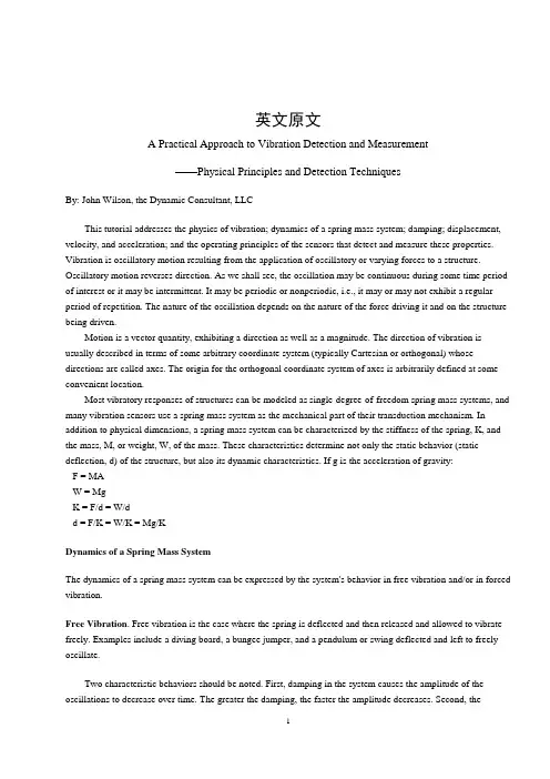
英文原文A Practical Approach to Vibration Detection and Measurement——Physical Principles and Detection TechniquesBy: John Wilson, the Dynamic Consultant, LLCThis tutorial addresses the physics of vibration; dynamics of a spring mass system; damping; displacement, velocity, and acceleration; and the operating principles of the sensors that detect and measure these properties. Vibration is oscillatory motion resulting from the application of oscillatory or varying forces to a structure. Oscillatory motion reverses direction. As we shall see, the oscillation may be continuous during some time period of interest or it may be intermittent. It may be periodic or nonperiodic, i.e., it may or may not exhibit a regular period of repetition. The nature of the oscillation depends on the nature of the force driving it and on the structure being driven.Motion is a vector quantity, exhibiting a direction as well as a magnitude. The direction of vibration is usually described in terms of some arbitrary coordinate system (typically Cartesian or orthogonal) whose directions are called axes. The origin for the orthogonal coordinate system of axes is arbitrarily defined at some convenient location.Most vibratory responses of structures can be modeled as single-degree-of-freedom spring mass systems, and many vibration sensors use a spring mass system as the mechanical part of their transduction mechanism. In addition to physical dimensions, a spring mass system can be characterized by the stiffness of the spring, K, and the mass, M, or weight, W, of the mass. These characteristics determine not only the static behavior (static deflection, d) of the structure, but also its dynamic characteristics. If g is the acceleration of gravity:F = MAW = MgK = F/d = W/dd = F/K = W/K = Mg/KDynamics of a Spring Mass SystemThe dynamics of a spring mass system can be expressed by the system's behavior in free vibration and/or in forced vibration.Free Vibration. Free vibration is the case where the spring is deflected and then released and allowed to vibrate freely. Examples include a diving board, a bungee jumper, and a pendulum or swing deflected and left to freely oscillate.Two characteristic behaviors should be noted. First, damping in the system causes the amplitude of the oscillations to decrease over time. The greater the damping, the faster the amplitude decreases. Second, thefrequency or period of the oscillation is independent of the magnitude of the original deflection (as long as elastic limits are not exceeded). The naturally occurring frequency of the free oscillations is called the natural frequency, f n:(1)Forced Vibration. Forced vibration is the case when energy is continuously added to the spring mass system by applying oscillatory force at some forcing frequency, f f. Two examples are continuously pushing a child on a swing and an unbalanced rotating machine element. If enough energy to overcome the damping is applid, the motion will continue as long as the excitation continues. Forced vibration may take the form of self-excited or externally excited vibration. Self-excited vibration occurs when the excitation force is generated in or on the suspended mass; externally excited vibration occurs when the excitation force is applied to the spring. This is the case, for example, when the foundation to which the spring is attached is moving.Transmissibility. When the foundation is oscillating, and force is transmitted through the spring to the suspended mass, the motion of the mass will be different from the motion of the foundation. We will call the motion of the foundation the input, I, and the motion of the mass the response, R. The ratio R/I is defined as the transmissibility, Tr:Tr = R/IResonance. At forcing frequencies well below the system's natural frequency, R I, and Tr 1. As the forcing frequency approaches the natural frequency, transmissibility increases due to resonance. Resonance is the storage of energy in the mechanical system. At forcing frequencies near the natural frequency, energy is stored and builds up, resulting in increasing response amplitude. Damping also increases with increasing response amplitude, however, and eventually the energy absorbed by damping, per cycle, equals the energy added by the exciting force, and equilibrium is reached. We find the peak transmissibility occurring when f f f n. This condition is called resonance.Isolation. If the forcing frequency is increased above f n, R decreases. When f f = 1.414 fn, R = I and Tr = 1; at higher frequencies R <I and Tr <1. At frequencies when R <I, the system is said to be in isolation. That is, someof the vibratory motion input is isolated from the suspended mass.Effects of Mass and Stiffness Variations. From Equation (1) it can be seen that natural frequency is proportional to the square root of stiffness, K, and inversely proportional to the square root of weight, W, or mass, M. Therefore, increasing the stiffness of the spring or decreasing the weight of the mass increases natural frequency.DampingDamping is any effect that removes kinetic and/or potential energy from the spring mass system. It is usually theresult of viscous (fluid) or frictional effects. All materials and structures have some degree of internal damping. In addition, movement through air, water, or other fluids absorbs energy and converts it to heat. Internal intermolecular or intercrystalline friction also converts material strain to heat. And, of course, external friction provides damping.Damping causes the amplitude of free vibration to decrease over time, and also limits the peak transmissibility in forced vibration. It is normally characterized by the Greek letter zeta () , or by the ratio C/C c, where c is the amount of damping in the structure or material and C c is "critical damping." Mathematically, critical damping is expressed as C c = 2(KM)1/2. Conceptually, critical damping is that amount of damping which allows the deflected spring mass system to just return to its equilibrium position with no overshoot and no oscillation. An underdamped system will overshoot and oscillate when deflected and released. An overdamped system will never return to its equilibrium position; it approaches equilibrium asymptotically. Displacement, Velocity, and AccelerationSince vibration is defined as oscillatory motion, it involves a change of position, or displacement (see Figure 1).Figure 1.Phase relationships among displacement, velocity, and acceleration are shown on these time history plots.Velocity is defined as the time rate of change of displacement; acceleration is the time rate of change of velocity. Some technical disciplines use the term jerk to denote the time rate of change of acceleration.Sinusoidal Motion Equation. The single-degree-of-freedom spring mass system, in forced vibration, maintained at a constant displacement amplitude, exhibits simple harmonic motion, or sinusoidal motion. That is, its displacement amplitude vs. time traces out a sinusoidal curve. Given a peak displacement of X, frequency f, and instantaneous displacement x:(2)at any time, t.Velocity Equation. Velocity is the time rate of change of displacement, which is the derivative of the time function of displacement. For instantaneous velocity, v:(3)Since vibratory displacement is most often measured in terms of peak-to-peak, double amplitude, displacement D = 2X:(4)If we limit our interest to the peak amplitudes and ignore the time variation and phase relationships:(5)where:V = peak velocityAcceleration Equation. Similarly, acceleration is the time rate of change of velocity, the derivative of the velocity expression:(6)and(7)where:A = peak accelerationIt thus can be shown that:V = fDA = 22 f2 DD = V/ fD = A/22 f2From these equations, it can be seen that low-frequency motion is likely to exhibit low-amplitude accelerations even though displacement may be large. It can also be seen that high-frequency motion is likely to exhibit low-amplitude displacements, even though acceleration is large. Consider two examples:• At 1 Hz, 1 in. pk-pk displacement is only ~0.05 g acceleration; 10 in. is ~0.5 g • At 1000 Hz, 1g acceleration is only ~0.00002 in. displacement; 100 g is ~0.002 in.Measuring Vibratory DisplacementOptical Techniques. If displacement is large enough, as at low frequencies, it can be measured with a scale, calipers, or a measuring microscope. At higher frequencies, displacement measurement requires more sophisticated optical techniques.High-speed movies and video can often be used to measure displacements and are especially valuable for visualizing the motion of complex structures and mechanisms. The two methods are limited by resolution to fairly large displacements and low frequencies. Strobe lights and stroboscopic photography are also useful when displacements are large enough, usually >0.1 in., to make them practical.The change in intensity or angle of a light beam directed onto a reflective surface can be used as an indication of its distance from the source. If the detection apparatus is fast enough, changes of distance can be detected as well.The most sensitive, accurate, and precise optical device for measuring distance or displacement is the laser interferometer. With this apparatus, a reflected laser beam is mixed with the original incident beam. The interference patterns formed by the phase differences can measure displacement down to <100 nm. NIST and other national primary calibration agencies use laser interferometers for primary calibration of vibration measurement instruments at frequencies up to 25 kHz.Electromagnetic and Capacitive Sensors. Another important class of noncontact, special-purpose displacement sensors is the general category of proximity sensors. These are probes that are typically built into machinery to detect the motion of shafts inside journal bearings or the relative motion of other machine elements. The sensors measure relative distance or proximity as a function of either electromagnetic or capacitive (electrostatic) coupling between the probe and the target. Because these devices rely on inductive or capacitive effects, they require an electrically conductive target. In most cases, they must be calibrated for a specific target and specific material characteristics in the gap between probe and target.Electromagnetic proximity sensors are often called eddy current probes because one of the most popular types uses eddy currents generated in the target as its measurement mechanism. More accurately, this type of sensor uses the energy dissipated by the eddy currents. The greater the distance from probe to target, the less electromagnetic coupling, the lower the magnitude of the eddy currents, and the less energy they drain from theprobe. Other electromagnetic probes sense the distortion of an electromagnetic field generated by the probe and use that measurement to indicate the distance from probe to target.Capacitive proximity sensor systems measure the capacitance between the probe and the target and are calibrated to convert the capacitance to distance. Capacitance is affected by the dielectric properties of the material in the gap as well as by distance, so calibration can be affected by a change of lubricant or contamination of the lubricant in a machine environment.Contact Techniques. A variety of relative motion sensors use direct contact with two objects to measure relative motion or distance between them. These include LVDTs, cable position transducers (stringpots), and linear potentiometers. All of these devices depend on mechanical linkages and electromechanical transducers.Seismic Displacement Transducers. These devices, discussed in detail later, were once popular but now are seldom used. They tend to be large, heavy, and short lived.Double Integration of Acceleration. With the increasing availability and decreasing cost of digital signal processing, more applications are using the more rugged and more versatile accelerometers as sensors, then double integrating the acceleration signal to derive displacements. While older analog integration techniques tended to be noisy and inaccurate, digital processing can provide quite high-quality, high-accuracy results.Measuring Vibratory VelocityTransducers. Some of the earliest "high-frequency" vibration measurements were made with electrodynamic velocity sensors. These are a type of seismic transducer that incorporates a magnet supported on a soft spring suspension system to form the seismic (spring mass) system. The magnetic member is suspended in a housing that contains one or more multiturn coils of wire. When the housing is vibrated at frequencies well above the natural frequency of the spring mass system, the mass (magnet) is isolated from the housing vibration. Thus, the magnet is essentially stationary and the housing, with the coils, moves past it at the velocity of the structure to which it is attached. Electrical output is generated proportional to the velocity of the coil moving through the magnetic field. Velocity transducers are used from ~10 Hz up to a few hundred Hz. They tend to be large and heavy, and eventually wear and produce erratic outputs.Laser Vibrometers. Laser vibrometers or laser velocimeters are relatively new instruments capable of providing high sensitivity and accuracy. They use a frequency-modulated (typically around 44 MHz) laser beam reflected from a vibrating surface. The reflected beam is compared with the original beam and the Doppler frequency shift is used to calculate the velocity of the vibrating surface. Alignment and standoff distance are critical. Because of the geometric constraints on location, alignment, and distances, they are limited to laboratory applications. One version of laser vibrometer scans the laser beam across a field of vision, measuring velocity at each point. The composite can then be displayed as a contour map or a colorized display. The vibration map can be superimposed on a video image to provide the maximum amount of information about velocity variations on a large surface.Integration of Acceleration. As with displacement measurements, low-cost digital signal processing makes it practical to use rugged, reliable, versatile accelerometers as sensors and integrate their output to derive a velocity signal.Measuring Vibratory AccelerationMost modern vibration measurements are made by measuring acceleration. If velocity or displacement data are required, the acceleration data can be integrated (velocity) or double integrated (displacement). Some accelerometer signal conditioners have built-in integrators for that purpose. Accelerometers (acceleration sensors, pickups, or transducers) are available in a wide variety of sizes, shapes, performance characteristics, and prices. The five basic transducer types are servo force balance; crystal-type or piezoelectric; piezoresistive or silicon strain gauge type; integral electronics piezoelectric; and variable capacitance. Despite the different electromechanical transduction mechanisms, all use a variation of the spring mass system, and are classified as seismic transducers.Seismic Accelerometer Principle. All seismic accelerometers use some variation of a seismic or proof mass suspended by a spring structure in a case (see Figure 3). When the case is accelerated, the proof mass is also accelerated by the force transmitted through the spring structure. Then the displacement of the spring, the displacement of the mass within the case, or the forcetransmitted by the spring is transduced into an electrical signal proportional to acceleration.Accelerometers. Transducers designed to measure vibratory acceleration are called accelerometers. There are many varieties including strain gauge, servo force balance, piezoresistive (silicon strain gauge), piezoelectric (crystal-type), variable capacitance, and integral electronic piezoelectric. Each basic type has many variations and trade names. Most manufacturers provide excellent applications engineering assistance to help the user choose the best type for the application, but because most of these sources sell only one or two types, they tend to bias their assistance accordingly.For most applications, my personal bias is toward piezoelectric accelerometers with internal electronics. The primary limitation of these devices is temperature range. Although they exhibit low-frequency roll-off, they are available with extremely low-frequency capabilities. They provide a preamplified low-impedance output, simple cabling, and simple signal conditioning, and generally have the lowest overall system cost.Most important to the user are the performance and environmental specifications and the price. What's inside the box is irrelevant if the instrument meets the requirements of the application, but when adding to existing instrumentation it is important to be sure that the accelerometer is compatible with the signal conditioning. Each type of accelerometer requires a different type of signal conditioning.Accelerometer Types. The most common seismic transducers for shock and vibration measurements are:∙Piezoelectric (PE); high-impedance output∙Integral electronics piezoelectric (IEPE); low-impedance output∙Piezoresistive (PR); silicon strain gauge sensor∙Variable capacitance (VC); low-level, low-frequency∙Servo force balancePiezoelectric (PE) sensors use the piezoelectric effects of the sensing element(s) to produce a charge output. Because a PE sensor does not require an external power source for operation, it is considered self-generating. The "spring" sensing elements provide a given number of electrons proportional to the amount of applied stress (piezein is a Greek word meaning to squeeze). Many natural and man-made materials, mostly crystals or ceramics and a few polymers, display this characteristic. These materials have a regular crystalline molecular structure, with a net charge distribution that changes when strained.Piezoelectric materials may also have a dipole (which is the net separation of positive and negative charge along a particular crystal direction) when unstressed. In these materials, fields can be generated by deformation from stress or temperature, causing piezoelectric or pyroelectric output, respectively. The pyroelectric outputs can be very large unwanted signals, generally occurring over the long time periods associated with most temperature changes. Polymer PE materials have such high pyroelectric output that they were originally used as thermal detectors. There are three pyroelectric effects, which will be discussed later in detail.Charges are actually not "generated," but rather just displaced. (Like energy and momentum, charge is always conserved.) When an electric field is generated along the direction of the dipole, metallic electrodes on faces at the opposite extremes of the gradient produce mobile electrons that move from one face, through the signal conditioning, to the other side of the sensor to cancel the generated field. The quantity of electrons depends on the voltage created and the capacitance between the electrodes. A common unit of charge from a PE accelerometer is the picocoulomb, or 10-12 coulomb, which is something over 6 × 10⁶ electrons.Choosing among the many types of PE materials entails a tradeoff among charge sensitivity, dielectric coefficient (which, with geometry, determines the capacitance), thermal coefficients, maximum temperature, frequency characteristics, and stability. The best S/N ratios generally come from the highest piezoelectric coefficients.Naturally occurring piezoelectric crystals such as tourmaline or quartz generally have low-charge sensitivity, about one-hundredth that of the more commonly used ferroelectric materials. (But these low-charge output materials are typically used in the voltage mode, which will be discussed later.) Allowing smaller size for a given sensitivity, ferroelectric materials are usually man-made ceramics in which the crystalline domains (i.e., regions in which dipoles are naturally aligned) are themselves aligned by a process of artificial polarization.Polarization usually occurs at temperatures considerably higher than operating temperatures to speed the process of alignment of the domains. Depolarization, or relaxation, can occur at lower temperatures, but at very much lower rates, and can also occur with applied voltages and preload pressures. Depolarization always results intemporary or permanent loss of sensitivity. Tourmaline, a natural crystal that does not undergo depolarization, is particularly useful at very high temperatures.Because they are self-generating, PE transducers cannot be used to measure steady-state accelerations or force, which would put a fixed amount of energy into the crystal (a one-way squeeze) and therefore a fixed number of electrons at the electrodes. Conventional voltage measurement would bleed electrons away, as does the sensor's internal resistance. (High temperature or humidity in the transducer would exacerbate the problem by reducing the resistance value.) Energy would be drained and the output would decay, despite the constant input acceleration/force.External measurement of PE transducer voltage output requires special attention to the cable's dynamic behavior as well as the input characteristics of the preamplifier. Since cable capacitance directly affects the signal amplitude, excessive movement of the cable during measurement can cause changes in its capacitance and should be avoided. Close attention should also be paid to the preamp's input impedance; this should be on the order of 1000 M or higher to ensure sufficient low-frequency response.In practice, a charge amplifier is normally used with a PE transducer.Instead of measuring voltage externally, a charge should be measured with a charge converter. It is ahigh-impedance op amp with a capacitor as its feedback. Its output is proportional to the charge at the input and the feedback capacitor, and is nearly unaffected by the input capacitance of the transducer or attached cables. The high-pass corner frequency is set by the feedback capacitor and resistor in a charge converter, and not the transducer characteristics. (The transducer resistance changes noise characteristics, not the frequency.) If time constants are long enough, the AC-coupled transducer will suffice for most vibration measurements.Perhaps the most important limitation of high-impedance output PE transducers is that they must be used with "noise-treated" cables; otherwise, motion in the cable can displace triboelectric charge, which adds to the charge measured by the charge converter. Triboelectric noise is a common source of error found in typical coaxial cables.Most PE transducers are extremely rugged. Each of the various shapes and sizes available comes with its own performance compromises. The most common types of this transducer are compression and shear designs. Shear design offers better isolation from environmental effects such as thermal transient and base strain, and is generally more expensive. Beam-type design, a variation of the compression design, is also quite popular due to its lower manufacturing cost. But beam design is generally more fragile and has limited bandwidth.Integral Electronics Piezoelectric (IEPE). Many piezoelectric accelerometers/force transducers include integral miniature hybrid amplifiers, which, among their other advantages, do not need noise-treated cable. Most require an external constant current power source. Both the input supply current and output signal are carried over the same two-wire cable. The low-impedance output of the IEPE design (see Figure 5) provides relative immunityto the effects of poor cable insulation resistance, triboelectric noise, and stray signal pickup.Output-to-weight ratio of IEPE is higher than with PE transducers. Additional functions can be incorporated into the electronics (see Figure 6), including filters, overload protection, and self-identification.Lower cost cable and conditioning can be used since the conditioning requirements are comparatively lax compared to PE or PR. The sensitivity of IEPE accelerometers/force transducers, in contrast to PR, is not significantly affected by supply changes. Instead, dynamic range, the total possible swing of the output voltage, is affected by bias and compliance voltages. Only with large variations in current supply would there be problems with frequency response when driving high-capacitance loads.A disadvantage of built-in electronics is that it generally limits the transducer to a narrower temperature range. In comparison with an identical transducer design that does not have internal electronics, thehigh-impedance version will always have a higher mean time between failures (MTBF) rating. In addition, the necessarily small size of the amplifier may preclude some of the desirable features offered by a full-blown laboratory amplifier, such as the ability to drive long cable. Slew limiting is therefore a concern with these transducers (some designs have relatively high output impedance) when driving long lines or other capacitive loads. The problem can be remedied by increasing the amount of drive current within the limit specified by the manufacturer.The circuits need not necessarily be charge converters because the capacitance due to leads between the sensor and the amplifier is small and well controlled. Quartz is used in the voltage mode, i.e., with source followers, because its small dielectric coefficient provides comparatively high voltage per unit charge. Voltage conversion also aids ferroelectric ceramics that have the sag in frequency response in charge mode due to their frequency-dependent dielectric coefficient. The amplitude frequency response in the voltage mode is quite flat.Piezoresistive. A PR accelerometer is a Wheatstone bridge of resistors incorporating one or more legs that change value when strained. Because the sensors are externally supplied with energy, the output can be meaningfully DC coupled to respond to steady-state conditions. Data on steady-state accelerations comes at a cost, however. The sensitivity of a bridge varies almost directly with the input excitation voltage, requiring a highly stable and quiet excitation supply .The output of a bridge configuration is the difference between the two output leads. A differential amplifier is required or, alternatively, both leads from the excitation must float to allow one of the output lines to be tied to ground. The differential configuration provides the advantage of common-mode rejection; that is to say, any noise signals picked up on the output lines, if equal, will be canceled by the subtraction in the amplifier.A cautionary note is in order here: With high-output PR transducers, there is a temptation to dispense with an amplifier and simply to connect the output leads directly to an oscilloscope. This will not work if both the scope and the excitation are single ended. Oscilloscopes often have single-ended input (the negative side of the input is ground). If the excitation is also grounded (with the excitation equal to ground), one leg of the bridge is shuntedand the entire excitation voltage is placed across that one leg of the bridge. If you are using AC coupling on the scope, you might misinterpret the reasonably shaped, but small and noisy, output.Most PR sensors use two or four active elements. Voltage output of a two-arm, or half-bridge, sensor is half that of a four-arm, or full bridge.Stability requirements for a PR transducer power supply and its conditioning are considerably tighter than they are for IEPE. Low-impedance PR transducers share the advantages of noise immunity provided by IEPE, although the output impedance of PR is often large enough that it cannot drive large capacitive loads. As is the case with an underdriven IEPE, the result is a low-pass filter on the output, limiting high-frequency response.The sensitivity of a strain gauge comes from both the elastic response of its structure and the resistivity of the material. Wire and thick or thin film resistors have low gauge factors; that is, the ratio of resistance change to the strain is small. Their response is dominated by the elastic response. They are effectively homogeneous blocks of material with resistivity of nearly constant value. As with any resistor, they have a value proportional to length and inversely proportional to cross-sectional area. If a conventional material is stretched, its width reduces while the length increases. Both effects increase resistance.The Poisson ratio defines the amount a lateral dimension is narrowed compared to the amount the longitudinal dimension is stretched. Given a Poisson ratio of 0.3 (a common value), the gauge factor would be 1.6; resistance would change 1.6 × more than it is strained. A typical gauge factor for metal strain gauges is ~2.The response of strain gauges with higher gauge factors is dominated by the piezoresistive effect, which is the change of resistivity with strain. Semiconductor materials exhibit this effect, which, like piezoelectricity, is strongly a function of crystal orientation. Like other semiconductor properties, it is also a strong function of dopant concentration and temperature. Gauge factors near 100 are common for silicon gauges, and, when combined with small size and the stress-concentrating geometries of anisotropically etched silicon, the efficiency of the silicon PR transducer is very impressive. The miniaturization allows natural frequencies >1 MHz in some PR shock accelerometers.Most contemporary PR sensors are manufactured from a single piece of silicon. In general, the advantages of sculpting the whole sensor from one homogeneous block of material are better stability, less thermal mismatch between parts, and higher reliability. Underdamped PR accelerometers tend to be less rugged than PE devices. Single-crystal silicon can have extraordinary yield strength, particularly with high strain rates, but it is a brittle material nonetheless. Internal friction in silicon is very low, so resonance amplification can be higher than for PE transducers. Both these features contribute to its comparative fragility, although if properly designed and installed they are used with regularity to measure shocks well above 100,000 g. They generally have wider bandwidths than PE transducers (comparing models of similar full-scale range), as well as smaller nonlinearities, zero shifting, and hysteresis characteristics. Because they have DC response, they are used when long-duration measurements are to be made.。
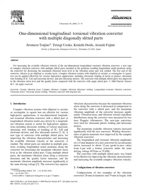
Ultrasonics38(2000)72–76www.elsevier.nl/locate/ultras One-dimensional longitudinal–torsional vibration converterwith multiple diagonally slitted partsJiromaru Tsujino*,Tetsugi Ueoka,Kenichi Otoda,Atsushi FujimiFaculty of Engineering,Kanagawa University,Yokohama221-8686,JapanAbstractFor increasing the available vibration velocity of the one-dimensional longitudinal–torsional vibration converter,a new type of complex vibration converter with multiple slitted parts installed in the positions avoiding longitudinal nodal positions along the converter for decreasing the maximum vibration stress level at the vibration nodal part was studied.The free end of the converter vibrates in an elliptical or circular plex vibration systems with elliptical to circular or rectangular to square loci can be applied effectively for various high-power applications,including ultrasonic welding of metal or plastics,ultrasonic wire bonding of IC,LSI and electronic devices,and also ultrasonic motors.The converter with multiple slitted parts was improved in the vibration stress level and the quality factor compared with the converter with single slitted part.©2000Elsevier Science B.V.All rights reserved.Keywords:Circular vibration locus;Complex vibration;Complex vibration ultrasonic welding;Longitudinal–torsional vibration converter; Ultrasonic motor;Ultrasonic plastic welding;Vibration converter with diagonal slits1.Introduction vibration characteristics because the maximum vibrationstress along the converter is decreased in comparison tothe converter with a slitted part,and the maximum Complex vibration systems with elliptical to circularvibration amplitude of the converter increases signifi-or rectangular to square loci are effective for variouscantly.Vibration locus,and vibration velocity and phase high-power applications.A one-dimensional longitudi-distributions along the converter were measured by two nal–torsional vibration converter with a slitted part atlaser Doppler vibrometers.The new-type converters longitudinal vibration nodal area driven by a longitudi-were used for ultrasonic plastic welding and ultrasonic nal vibration system is useful for high-power applica-motors.tions including ultrasonic welding of various materials,The maximum available vibration velocity increased ultrasonic wire bonding of bonding of IC,LSI andsignificantly with the new converter.Welding character-electronic devices,and also ultrasonic motors[1–4].Aistics of plastic materials were improved by the complex new type of converter with multiple slitted parts,forvibration converter.improving the vibration characteristics and increasingThe longitudinal and torsional vibration amplitudes the available vibration velocity of the converter,isof a15mm diameter of a new converter for an ultrasonic studied.The slitted parts are installed in multiple posi-motor increased to about12m m(peak-to-zero value) tions avoiding longitudinal nodal positions along thefrom6m m with a former converter under the same converter for decreasing the maximum vibration stress driving voltage60Vrms at55kHz.level at the vibration nodal ing multiple slitted The converter with multiple slitted parts was found parts,the maximum vibration stress along a converter to be effective for improving the vibration characteristics decreases and the quality factor increases,and the and increasing the available complex vibration velocity. maximum vibration amplitude increases significantly atthe same driving voltage[5].The converter has superior2.Configurations of vibration converters*Corresponding author.Tel.:+81-45-481-5661;Configurations of two examples of the vibration fax:+81-45-491-7915.E-mail address:tsujino@cc.kanagawa-u.ac.jp(J.Tsujino)converters20mm in diameter and79mm in length,with0041-624X/00/$-see front matter©2000Elsevier Science B.V.All rights reserved.PII:S0041-624X(99)00175-473J.Tsujino et al./Ultrasonics 38(2000)72–plex vibration ultrasonic plastic welding4.1.Vibration characteristics of a complex v ibration con v ertersFig.2shows the relationship between driving fre-quency and longitudinal and torsional vibration velocity of a complex vibration system with the vibration con-verter (a).The driving voltage is kept constant at 20Vrms.Longitudinal and torsional vibration velocities have maximum values at di fferent frequencies at around 26.3and 26.4kHz.The elliptical locus is obtained at the free edge of the converter.Torsional and radial vibration velocity distributions at 26.8kHz along a complex vibration converter with Fig.1.Various one-dimensional longitudinal to torsional vibration double slitted parts (a)and (b)are shown in Fig.3.One converters with double slitted parts.torsional vibration velocity nodal part is within a left slitted area,and the vibration velocities have maximum values at the free edge.The radial vibration velocity distribution along a slitted parts that were installed avoiding a longitudinal complex vibration converter with double slitted partsnodal part,are shown in Fig.1.The cylindrical longitu-dinal–torsional vibration converters,made of aluminum alloy (JISA7075B),had two slitted parts on both sidesof a longitudinal vibration nodal part at its circumfer-ence.The converters were driven by a longitudinal vibration source.Various converters with (a)di fferent and (b)the same angle diagonally slitted parts were made in the trials.The vibration converter part had 18diagonal slits of 45or 135°,10mm width and 0.5mm width were cut along its circumference using an electrosparking machine.The slit depth was altered from 1.0to 3.0mm.The free edge part of the converter vibrated longitudinally and torsionally and vibrated in an elliptical locus.Fig.2.Torsional and radial vibration velocity distributions along com-plex vibration converters (a)and (b).Driving voltage:20Vrms.3.Vibration characteristics of the converters with two slitted partsThe free admittance loops of the total vibration systems with the converters [Fig.1(a)and (b)]were measured.The quality factor and motional admittance,|Y mo|,of the vibration system with a converter with di fferent angle slitted parts (a)and the same angle slitted parts (b)were about 600and 30mS under welding conditions of two 1.0mm thick polypropyrene sheets with a static pressure of 890kPa.The admittance loops of the vibration system with the converters show single circular shapes because the resonance frequencies of the longitudinal and torsional vibrations are close.The quality factors and motional admittances of the both Fig.3.Relationship between driving frequency,and longitudinal and systems are large.Elliptical loci were obtained at the torsional vibration velocity of a complex vibration system with a vibra-tion converter (A).Driving voltage:20Vrms.free edges of the converters.74J.Tsujino et al./Ultrasonics38(2000)72–76(a)is also shown in Fig.3(dotted line).A radial and double slitted parts.In the case of the converterwith single slitted part,the slitted part is positioned at vibration velocity maximum position means a longitudi-a nodal position of the longitudinal vibration along the nal vibration nodal position,and the longitudinal nodalcylindrical longitudinal–torsional vibration converters. position is positioned between two slitted parts.TheOn the contrary,in the case of the converter with two two slitted areas exist out of the longitudinal nodalslitted parts,the slitted parts are positioned avoiding position where the vibration stress has a maximum valuethe longitudinal vibration nodal position.The converter along the converter.with diagonal slits is driven by a longitudinal vibrationsource of two piezoelectric ceramic(lead–zircon–tita-4.2.Welding characteristics of complex v ibrationnate;PZT)disks,15mm in diameter and5.0mm in ultrasonic plastic weldingthickness.The vibration converter slitted part has12diagonal slits of45or135°and0.5mm in width and10 The relationship between welding time,specimenor5mm in length,cut by an electrosparking machine deformed thickness at the welded parts and the weldalong the circumference of these converters fabricated strength of the lapped polypropyrene sheets(1.0mm infrom aluminum alloy(JISA7075B).The slit depths of thickness),welded using a27kHz complex vibrationthe15mm diameter converter are altered from1.5to system with a converter(a)and(b),is shown in Fig.4.3.5mm.The free edge of the converter vibrates longitu-The weld strengths obtained by the system with con-dinally and torsionally and vibrates in an elliptical locus. verter(a)are larger than those with a converter(b).The PZT longitudinal vibration transducers,a longi-The welding time required becomes shorter using thetudinal vibration rod with aflange for supporting the vibration system(a)with a larger torsional vibrationmotor and a slitted cylinder are clamped by a connecting component.The decrease in specimen deformed thick-bolt.The driving part of the converter and the rotor ness at the welded parts roughly corresponds to thepart are statically pressed using corned disk springs by obtained weld strength.Specimens were welded in aa center bolt and nuts.The driving surfaces of the shorter welding time using a complex vibration systemconverter(JISA7075B)and the rotor(steel:SKD-61or compared with a longitudinal vibration plexSK-4:tempered)are ground to beflat and smooth using vibration is effective for ultrasonic welding of plastic1500–2000mesh polishing powder.materials as for metal materials.5.2.Vibration characteristics of15mm diameterultrasonic motors5.Ultrasonic motors with a longitudinal–torsionalconverterThe longitudinal and torsional vibration amplitudesat the free edge of these converters were measured by 5.1.Configuration of ultrasonic motors two laser Doppler vibrometers when the driving fre-quency was altered.These converters have near-reso-The configurations of the ultrasonic motors and nance frequencies of the longitudinal and torsional vibration converters,15mm in diameter,are shown in vibrations similar to Fig.2.The largest longitudinal Fig.5.Fig.5(a)and(b)show the configurations of vibration amplitudes of the converter of single and two 15mm diameter motors using a converter with single slitted parts without a rotor part were about6and12m m(peak-to-zero value)at frequencies of50–55kHz.The largest longitudinal vibration amplitudes of theseconverters with a rotor part are about3and9m m atfrequencies near to55kHz.The largest vibration ampli-tudes of a converter with double slitted parts are abouttwo to three times compared with the amplitudes of aconverter with single slitted part.5.3.Vibration loci at the dri v ing surface of the con v erterIn these cases,the longitudinal vibration is partiallyconverted to torsional vibration at the slitted parts,andthe cylinder part of the converter vibrates longitudinallyand torsionally.The vibration locus at the free edge isdetermined by the vibration phase difference between Fig.4.Relationship between welding time,deformed weldment heightthese vibrations.Vibration loci at the driving surfaces and weld strength of the lapped polypropyrene sheets(1.0mm in thick-of longitudinal–torsional converters were measured ness),welded using a27kHz complex vibration system with a converter(a)and(b).using two laser Doppler vibrometers(~20MHz)that75J.Tsujino et al./Ultrasonics38(2000)72–76Fig.5.Configurations of15mm diameter ultrasonic motors using a longitudinal–torsional vibration converter with single slitted part(a)and double slitted parts(b).detect longitudinal and torsional vibrations indepen-length of the ultrasonic motor of15mm diameter in the dently.The vibration locus is shown on a digital memorydriving frequency55.1kHz(without a rotor)and oscilloscope screen as a Lissajousfigure.Fig.6shows54.26kHz(with a rotor).The vibration locus amplitude the vibration loci at the driving surfaces of convertersat the driving surfaces of converter decreases slightly with double slitted parts of3.3mm depth and5mm when the ultrasonic motor rotates.Fig.6.Vibration loci at a driving part of a15mm diameter converter with and without a rotor part.76J.Tsujino et al./Ultrasonics38(2000)72–766.Conclusion materials.The15mm diameter ultrasonic motor,together with a converter with double slitted parts, For increasing the available vibration velocity of therotated at over300rpm.complex vibration converter,a new type of converter The converters with multiple slitted parts were found with multiple slitted parts was studied.to be effective for improving the vibration characteristics This converter has multiple slitted parts that are and increasing the available complex vibration velocity. installed in multiple positions,avoiding nodal positionsalong the converter for decreasing the maximum vibra-tion stress level at the vibration node part.The weldingReferencescharacteristics of ultrasonic plastic welding using com-plex vibrations were studied.Also,15mm diameter[1]J.Tsujino,T.Ueoka,T.Shiraki,K.Hasegawa,R.Suzuki,M. ultrasonic motors using converters with double slittedTakeuchi,Proc.Int.Congress on Acoustics(1995)447–450.. parts were tested.[2]J.Tsujino,Proc.IEEE1995Ultrasonics Symp.,IEEE,New York,The longitudinal vibration nodal part was located1996,pp.1051–1060.between two slitted parts of the converters.The driving[3]J.Tsujino,T.Uchida,K.Yamano,T.Iwamoto,T.Ueoka,Proc. surface of the converter and the ultrasonic motor with2nd World Congress on Ultrasonics,Yokohama,Japan(1997)152–153.double slitted parts vibrated at higher vibration velocities[4]J.Tsujino,T.Uchida,K.Yamano,T.Iwamoto,T.Ueoka,Proc. than those with a single slitted part at the same driv-IEEE1997Ultrasonics Symp.,IEEE,New York,1998, ing voltage.pp.855–860.The converter with double slitted parts significantly[5]J.Tsujino,T.Ueoka,Proc.IEEE1999Ultrasonics Symp.,IEEE, improved the ultrasonic welding characteristics of plasticNew York,1999,pp.723–728.。
LabVIEW分析工业环境中机械振动的实际应用Ioan Lita, Daniel Alexandru Visan, Gelu Mujea, Dan GhitaElectronics and Computers Department, University of PitestiStr. Targul din Vale, , Pitesti, ROMANIAlita@., visan@摘要在简要的介绍机械振动的源头及其对工业环境的影响后,在本文提出一个新的机械振动的通用监测及分析系统。
在这项工作中提出的配置系统的目的是用于分析和监测的工业机器的机械振动。
该系统的主要有三部分:连接到个人电脑的数据采集板,振动传感器,在LabVIEW图形化编程环境下实现的分析和控制软件。
所提出的方案与其他类似的方案相比,它的主要优点是它所具有灵活性。
该软件相对其他机械振动分析软件容易操作得多,例如:地球动力学/振动监测系统;公路,桥梁或塔监控系统。
此外,该设备是很容易扩展到更多的传感器,可以安装迅速,具有友好的图形界面,但不昂贵。
1.引言监测环境振动的能力是重要的,无论是从研究的角度看,还是工业应用方面,如自适应控制,状态监测,工艺优化和质量控制。
直到今天,大量的工作已经完成,如在环境机械振动分析,工具等方面的监测和控制等等。
例如,有一种日益增长的趋势,指明建筑振动的临界值,限制值条件,临界值是指有干扰和不确定性下的振动水平,限制值是指可能振动干扰的振动水平。
这些值通常用在建筑规格,控制报告频率和预先计划的执行情况和减轻补救行动。
此外,在工业领域,这个类似的系统,在这项工作提出了允许各种机械的连续监测,提供信息服务,便于对故障或故障早期检测。
这样就能预防更进一步严重故障甚至损坏,要不可能会损害机器的性能或危及厂房及操作人员。
为监测环境和机器的状况,可以使用计算机的多种传感器。
在这方面的工作,它有简单,灵活,操作方便等优越性。
[波动的英文]波动的近义词及解释近义词:颠簸、振动、震动、震撼、震荡、摇动、动摇颠簸:颠簸diānbǒ[bump;jolt;toss] 一连串的突上突下的上下震荡吉普车转了个弯又颠簸起来了颠簸碰伤的水果在波浪中颠簸的小船振动:振动zhèndòng[vibration] 物体的全部或一部分沿直线或曲线往返颤动,有一定的时间规律和周期无规则振动震动:震动zhèndòng(1) [jolt]∶颤动每次爆炸都受到猛烈的震动(2) [shake]∶使颤动哭声震动天地。
——明· 张溥《五人墓碑记》(3) [shock]∶使人心里不平静消息震动了全国震撼:震撼zhènhàn(1) [shock]∶指心理受到强烈冲击;憾动自然科学上的发现震撼了欧洲人的普遍心理(2) [rock]∶使猛烈震动炮兵部分演习的时候寂静的农村被大炮的隆隆声所震撼震荡:震荡zhèndàng(1) [shake]∶震动雷声震荡着大地(2) [vibrate]∶处于动荡状态震荡不宁摇动:摇动yáodòng(1) [wave;sway;shake;rock]∶摇东西使它动大树在狂风中摇动(2) [swing]∶摆动当豪猪摇动尾巴的时候,就跳向一旁动摇:动摇dòngyáo(1) [sway;vacillate;shake]∶在两种对立的意见之间或在两条对立的行动路线之间摇摆不定(2) [waver]∶不坚定,不稳固(3) [infirm]∶使不坚定反义词:稳定、动荡、晃动、激烈、平稳稳定:稳定wěndìng(1) [stable;firm;steady](2) 稳固安定稳定的多数稳定的货币(3) 指物质不易被腐蚀或性能不易改变性能稳定的乳胶动荡:动荡dòngdàng[upturn;turbu lence] 比喻情况或局势不安定关于激烈的社会动荡的真相动荡dòngdàng[turbulent] 不稳定的;不平静的动荡的局势晃动:晃动huàngdòng(1) [waggle]∶来回摇动或上下摆动,尤指反复地和急促地或波浪式地摇动一些船在停泊处微微晃动(2) [sway;shake]∶被重量、压力或施加的力量所摇晃地震使墙壁晃动得向右边倾侧激烈:激烈jīliè(1) [intense](2) 剧烈激烈争辩(3) 声音高亢激昂;激越激烈的演说平稳:平稳píngwěn(1) [smooth and steady;smooth;stable](2) 没有波动,稳定物价平稳日子过得平稳(3) 平安稳当;平和稳重平稳得荆州。
振动的分类1、共振。
系统受外界激励,作强迫振动时,若外界激励的频率接近于系统频率,强迫振动的振幅可能达到非常大的值,这种现象叫做共振。
一个系统有无数个固有频率,我们常研究低范围的系统频率。
共振是物理学上,一个运用频率非常高的专业术语。
共振的定义是两个振动频率相同的物体,当一个发生振动时,引起另一个物体振动的现象。
共振在力学中亦称“共鸣”,它指的是物体因共振而发声的现象,如两个频率相同的音叉靠近,其中一个振动发声时,另一个也会发声。
共振的英语是resonance,谐振与共振是同一个意思。
2、涡振。
涡振是指在平均风作用下,有绕流实腹断面后交替脱落的涡旋引起的振动。
桥梁涡振研究是空气动力学的一个分支学科。
桥梁涡振是一种兼有自激振动和强迫振动特性的有限振幅振动,它在一个相当大的风速范围内,可保持涡激频率不变,产生一种“锁定”(lock-on) 现象。
桥梁涡激共振的有限振幅计算是一个十分重要但又异常困难的问题,目前国内外还没有形成一套比较完整的桥梁涡振分析理论。
实用上,采用一种半理论半实验的方法,以近似地估算涡激共振的振幅。
涡振的英语是vortex-induced oscillation。
3、颤振。
颤振指的是在气动力的作用下,由于结构本身具有弹性和惯性,流动与结构互相耦合作用而发生的一种自激振动现象。
抖振通常指的是由于流动本身存在分离、激波附面层干扰等非定常特性,导致加载在弹性结构上的气动力呈现周期性而造成的结构强迫响应。
也就是说在传统定义下,经典颤振是一种自激振动。
除此之外,还有大攻角下的失速颤振现象,有的学者认为这类存在强分离条件的结构振动是颤振与抖振共存的。
颤振的英语是flutter。
4、抖振。
抖振在飞机中是指,在分离气流或尾流激励下发生的飞机部件按结构自然频率的振动。
抖振的最主要例子是飞机的尾翼抖振。
当尾翼处于机翼、机翼——机身接合部或其他部件的尾流中时,尾流中的扰动迫使尾翼作强烈的振动。
在飞机作大迎角飞行时,特别容易发生尾翼抖振,在历史上曾造成严重事故。
电机常用英语词汇一、总装配 general assembly座式轴承 pedestal bearing滑动轴承 sliding bearing滚动轴承 roll bearing轴瓦 bearing shell轴承座 bearing pedestal轴承内盖 internal bearing cover轴承外盖 external bearing cover气隙 air gap磁力中心 magnetic center轴瓦间隙 clearance between shaft and shell振动 vibration双倍振幅值 double amplitude振速 vibration speed定子电密 stator current density热负荷 specific heat load(W/cm2)磁场 magnetic field振动加速度 vibration speed mm/s Acceleration unites mm/s2 电磁感应 electromagnetic induction内圈 inner ring外圈 outer ring滚动体 roller保持架 cage端盖 end cover底板 base plate垫片 spacer轴承测温元件 bearing temperature probe三相交流电three-phase alternative current 温升 temperature rise对地击穿 earth breakdown击穿电压 breakdown voltage金属热处理 metal heat treatment无氧退火natural cooling60度相带 60 degrees phase zone主接线盒 main terminal box加热器接线盒 heater auxiliary terminal box 定子测温接线盒 stator probe terminal box 电流互感器 current transformer差动保护 differential protection速度传感器 speed sensor侧水冷 side water cooling冷却器 cooler空-空冷却器 air-air cooler穿管工艺 pipe流水线 pipeline轴伸端 shaft end or driving end非轴伸端 non driving end漏油 oil leakage轴承密封 bearing seal底脚螺栓 anchor bolt弹簧垫圈 spring washer定位销 positioning pin or locating pin 游动间隙 clearance对组试验 head to head test空载电流 no load current起动电流 starting current有功功率 active power无功功率 reactive power旋转磁场 rotating magnetic field电磁噪音 electromagnetic noise喘振 surge安装尺寸 installation dimension轴伸键 shaft key键槽 key slot现场测试 factory acceptance test (FAT)空载试验 no load test温升试验 temperature rise test堵转试验 rotor blocked test高压摇表 high voltage megohm meter 无刷励磁 brushless excitation励磁机 exciter功率因数 power factor起动电流 starting current起动转矩 starting torque最大转矩 maximum torque效率 efficiency二、定子装配 stator assembly定子 stator定子线圈 coil定子冲片 lamination定子槽型 stator slot节距 pitch槽楔 wedge槽绝缘 slot insulation开口槽 open slot闭口槽 close slot电晕 corona低阻带 low resistance tape高阻带 high resistance tape每极每相槽数 number of slots per pole per phase 分数槽 fractional slot云母带 mica tape半导体材料 semi-conductor material垫条 strip环氧玻璃布板 epoxy bonded fiber-glass board补强材料 reinforcing material真空浸漆 VPI定子下线 winding定子接线 connecting定子引线 lead高压电缆 high voltage cable线圈上层边 top lead双层叠绕组 two tier coil齿压片 tooth supporter通风槽板 vent spacer线圈直线部分 straight part线圈端部 end winding线圈绑绳 coil fixation strip层间垫条 separator端箍 end winding fixation铁耗试验 core loss test加强筋 strengthening bar电机风路 motor wind path半成品试验 semi-product test耐压试验 voltage withstanding test匝间试验 inter turn test冲击电压 impulse voltage直流脉冲 DC pulse击穿场强 breakdown strength定子接线 stator connecting绕组系数 winding factor短矩系数 short pitch factor分布系数 distribution factor接地 earth交流耐压试验 AC voltage withstanding test半成品 semi-product铂电阻 platinum resistance灭磁电阻 de-excitation resistance极相组数 number of groups per pole per phase 高速电动机 high speed motor拉紧螺杆tightening bolt鸽尾槽 dovetail slot三、转子装配 rotor assembly汽轮发电机转子 turbo generator rotor 风力发电机转子wind generator rotor轴流式风扇 shaft flow fan铸铝转子 cast-aluminum rotor铜条转子 copper bar rotor铜端环 copper end ring焊接应力消除 welding stress release 时效处理aging treatment自然时效 natural aging振动时效 vibration aging静平衡static balance动平衡dynamic balance离心式风扇centrifugal fan风叶blower fans风扇内板 inner plate风扇座 fan pedestal集肤效应 skin effect双鼠笼转子 double squirrel-cage rotor 梯形槽 terrace slot显极 salient pole隐极 non salient pole双层波绕组 bi-layer wave winding轴深孔 shaft deep hole转子车加工 rotor lathing轴磨加工 shaft grinding轴承室 bearing cavity挡风板 wind deflector风路循环 wind cycling轴向通风 shaft ventilation频敏电阻 frequency sensitive resistance 风力发电 wind generator机械加工工艺 mechanical machining磨加工 grinding铣键槽 milling key双面镗床 bidirectional boring machine 落地镗床 ground borer气隙不均度 air gap irregularity轴弯曲 shaft bending轴变形 shaft deformation冷挤压 cold extrusion金属热处理 metal heat treatment转子吊具 rotor lifter专用工装 special tooling中频焊工艺 mid-frequency welding 钻孔 drilling镗孔 boring欢迎您的下载,资料仅供参考!致力为企业和个人提供合同协议,策划案计划书,学习资料等等打造全网一站式需求。
红外振动类型的英文表示方法及其全称(remove the research barrier)1、红外光谱的产生和表示在分子的振动过程中,只有那些能引起分子偶极矩改变的振动,才能吸收红外辐射,从而在红外光谱中出现吸收谱带。
多原子分子的振动是由许多简单的、独立的振动组合而成的。
在每个独立的振动中,所有原子都是以相同相位运动,可以近似地看作谐振子振动。
这种振动称为简正振动。
每个简正振动具有一定的能量,故应在特有的波数位置产生吸收。
由n个原子组成的多原子分子存在有3n—6个简正振动,而线型分子则为3n—5个简正振动。
在简单分子中,对这些基本振动进行理论解析是可能的,但在实际的复杂有机化合物中,简正振动数目很多,而且由于倍频振动和组合频振动也会出现吸收,所以使红外光谱变得很复杂。
对于所有的红外吸收谱带在理论上进行解析将是非常困难的。
因此,当红外光谱用于定性分析时,通常是利用各种特征频率吸收图表,选出与官能团和骨架构有关的吸收谱带,而且还要与待定化合物的标准光谱相比较才能得出结论。
红外光谱图的横坐标一般用波数v(单位cm-1),纵坐标常用百分透过率(T%)表示。
2、多原子分子的振动方式基团的各种振动类型用如下符号来表示:ν伸缩振动γ面外弯曲振动δ变形振动β面内弯曲振动 t扭绞振动τ扭转振动ω面外摇摆振动 s对称振动 as不对称振动r面内摇摆振动3、吸收带强度吸收带的强弱主要取决于分子振动时偶极矩变化的大小。
分子的对称性越高,偶极矩的变化越小,吸收带越弱。
一般,仅含碳和氢的化合物的吸收是较弱的。
但是由电负性差别显著的原子所组成的键,如c—N、c—o、c=o、c=N等,其吸收带一般都是很强的。
吸收带的强度用表观摩尔吸光系数来表示,也用如下符号来表示:VS(very strong,极强),S(strong,强),M(medium,中),w(weak,弱),Vw(very weak,极弱)。
红外线:infrared ray,IR中红外吸收光谱:mid-infrared absorption spectrum,Mid-IR远红外光谱:Far-IR微波谱:microwave spectrum,MV红外吸收光谱法:infrared spectroscopy红外分光光度法:infrared spectrophotometry振动形式:mode of vibration伸缩振动:stretching vibration。
流量测量和仪表 利用实验和数值研究尾缘形状对三维轴流 风机出风口气体流动的影响
—、■ 6 : I-2—t
文早信息:
文章来历
接收 2009年3月15日 修订 2009年8月13日 收录 2010年2月5号 摘要:
本文的主要目的是研究轴流风机尾缘结构对风机出风口湍流流动的影响。 本文研究的风机主要为三个低气压且低马赫的轴流式风机, 分别为径向,向前和 向后扫描三种不同的叶轮结构。本文采用了实验和计算流体动力学( CFD)方法 对三个风扇进行了研究,并对结果进行了相应的比较。该方法是一个用三维(3D) 的雷诺平均方程和纳维斯托克斯方程与雷诺应力模型作为湍流模型( RSM )的 数值模拟方法。它使我们能够计算出雷诺应力张量的分量。 不平稳速度的测量可 利用风扇下游的热线技术来测定,并对三个速度组分量与从利用实验和模型得到 的雷诺兹应力张量的六个组分的值进行比较。 同时,此现象还用于验证设计和风 扇模型的正确性。由此最终得到,前缘减少了组元径向的速度,而尾缘则增加了 这部分的速度。此外,尾缘对风扇下游湍流的动量有重要影响作用。
引言: 涡轮机械中流体的流动情况非常复杂。 他们的共同特征是三维的、粘性的和 不稳定的特征。几何特点及运行情况对涡轮机械中的流体流动也有重大的影响
不稳定的气动力现象常常是出现在空气动力性数值减少的情况下, 而且它们也是
关键词:轴流风机 尾缘 热线技术 雷诺应力模型 产生噪声和驰振现象的原因。因此非稳态流在对轴流风机进行调查的时候是一个 重要的课题内容。对于那些复杂的流动研究,可利用不同的紊流模型进行数值模 拟。计算流体动力学(CFD)工具可使那些用纳维尔斯托克斯方程的无法给出的不 稳定气动特性的流动特性问题得以解决。 而且,利用直接数值模拟或大涡模拟方 法对于像涡轮机械这样复杂的几何流体力学工业中的代价是非常昂贵的。 本文的目的是为了确定蜗舌对风机尾缘的下游速度分量的影响。 这些不稳定 部件可以分为确定性的和随机性的两部分。 确定性部分为叶片通道频率及其倍频 的离散成分。它由转子叶片及其环境之间的周期性的不稳定的作用力而产生。 随 机性部分主要是由于在旋转的叶片翼周围存在紊乱流场,因而促使所有的频率超 过了 5到20万赫兹的频带范围。 本文提出了一种初步的噪音预测方法的研究。 且将湍流产生的动能作为噪声 预测模型的输入[1,2]。雷诺应力模型的湍流模块能够使我们精准的计算湍流流 动所具有的动量(4.3部分)。 本文以汽车冷却系统中的轴流式风机作为个案进行研究。因为它们常常受较 差的流入条件所牵制。正由于这个流入状况产生了周期性的和随机性的力, 导致 了一定音频和带宽的噪音。此外,由于叶片表面上的湍流边界层的交互作用与尾 缘的作用产生的波动不平的力使得风机产生了宽频的独立噪音。 使用对降噪叶片扫尾对降低噪声似乎是有效的。汉森 [3]主要研究了通过取 消产生噪声的所处不同径向相位的位置降低叶片的噪声音调的问题。 他还研究叶 片对叶片的相互干扰。通过他的研究结果,可以看到大角度的叶尾对于叶片之间 的作用是非常有利的,尤其对于低速转子,与亚拉巴马州的夫卡诺[4]、科明斯⑸ 等人的研究是类似的。此外,夫基塔 ⑹的实验表明,合理数值的尾缘对降低噪 声也相当的有利。 值得一提的是,艾维亚[7]与卡尔森[8]的研究工作似乎还为选择叶片尾缘角 度的分布提供了理论依据。该理论对降低湍流因素所产生的噪声的降低有明显的 影响。将之应用于低速轴流风机的前后尾缘,不但改变了噪声源的空间分布 ,也 使得它们不会在刀片半径范围内同时产生。 这样产生相位变换变为沿翼展方向上 的的压力和速度分量和在的破坏性或建设性的结果之间的干扰, 从而对辐射噪声 进行修改。有关空气动力和车内的声学特性的具有叶片尾缘的轴流式风机的完整 的文献在参考书目[9]中有具体分析。 雷诺纳维尔数值模拟稳定和不稳定的加载在叶片的力和福克斯威廉霍金姆 斯的构想可以用来辅助声调部分音谱[10]所聚集的叶轮。为了空间的统一而非时 间不稳定的流动,但是,雷诺纳维尔数值模拟作为宽频噪声预测的方法是行不通 的。宽频噪声的预测来源的模拟数值需要高精度数值。亚拉巴马州的卡洛斯 [11] 曾利用热线技术获得为各种不同的流入配置使用的湍流静态数据库统计。 这些结 果被拿来与莱斯的模拟结果作为比较。莱斯预测 LES的影响叶片波动动荡和风 机噪声与其有利的实验相比较。莱斯莱斯模型不但工业耗能价格昂贵, 而且不如 雷诺纳维尔斯托克斯动量方程的计算更有用的[1,2]。 第二部分提出了用实验装置来测量风机下游的三维不稳定速度分量。 测量是 通过热线技术测量风机下沿半径流体的通过量。分析动荡的波动数据,元件的速 度紊动应力张量可用湍流动能来描述。然后模拟三种不同的风机(第三部分)的模 型和计算。最后,其结果将在第四部分进行比较与分析。
2、实验装置
这项研究所采用的风机样为三个轴流式风机原型。其叶片按叶片伸展方向 为三种不同方式的径向辐射状。如图1所示:
C2for G2rad G2back 轲1 0223 0.248 0.247
1 0289 0330 0314
表1 三风机工作时的流动效率 第一个风机模型所展示的为径向扫掠状结构(G2rad),第二个为向前旋转 式扫掠状模型(G2for),而第三个为向后旋转式扫掠状模型(G2back)。对于第 二和第三模型而言,其扫略模型为对称结构,但是其它的几何结构确实同样的, 每一个风机都有八片风叶。三个轴流式风机的结构设计有如下特征: 外部半径 Rext =187.5mm 内部半径 Rint =85mm 相隔错开角度为75 ° 护罩的厚度为 2.5mm 转子建立在一根用细长的最大值厚度仅为 55毫米的沿眉形线的NACA0065 叶片上,在前缘和拖尾处以圆弧过渡,其旋转速度是 45HZ。 根据表1可知,对于所有测量的名义流动速率,三个风机的名义流动速率
9 为 1.3 n 。
2.1试验设备 在这项研究中,采用了连续温度测量技术(CTA),因为它能够快速、精确的 传递时间系列和宽带光谱信号。根据径向平衡的假说,轴流式风机应该是可以忽 略二维流动和径向组件的绝对速度。 但是这种情况很少,因为观察同心圆空气管 之间的能量转移,对轴流式风机三维流场的描述还是需要的。 同时,风机的主轴 转动切向和径向分量的测量速度必须和之前估算的值进行对比。 用一个2D Dan tec 55R51的热纤维膜探测器测量分量部分的瞬时速度。可 测量两不同角度的测量位置的物理值, 以确定三个速度分量。因而,采用一个可 旋转90度的轴探针进行测量。使用一个 2D探针得到如同描述的完整的空间结 构的流场,完整的测量系统由一个 5H24探针点测的情况下,如果一个采用连续 温度测量技术的每线最小 CTA的54T30,一个标准的PCI6048-E型A / D,和 一个转数表和一个能使抽样信号达到 250千赫兹的触发器的相应软件CTA V3.4, 如图2和图3显示的实验设备。根据ISO5801标准[12]设计和建造的空气试验台, 能使空气流动速度在设计点的控制范围内,并且选择适当的孔板直径。 在风机下游采用11等分分布的均匀径向间隔热线探测器定位点探测, 离尾 缘在中心10毫米处,风机的转角B如(图4)。测量得到B绝对角速度基本为中等 转速。绝对速度角度依赖于风机机构和流量, 所以每个风机测定值是不同的。 此 外,这个沿半径角度变化的结构如图 3。在所有测量点中,以绝对转速适中的点 图.3 图.4 热线探测技术(CTA)系统以每1000样品中45千赫的频率取样。这些数据是 由20批次的风机样本收集而来。
2.2校准和不确定度分析 校准建立在通过静压的探针装置测量的输出速度和流速之间的关系式,然 后记录了其电压,即通过拟合点(E,U)代表传递函数被用来当转换数据记录在电 压的效应。为了得到更好的精度,取介于1m/s到25m/s的速度值之间选择20个 按对数分布的速度采集点,然后,利用软件计算四次多项式传递函数的值。 在一个自由的空气装置之前和之后进行探测器校准, 检测并控制其漂移量。 校准的工作台由一种大容量的具有恒定压力和一个与外界大气相通的小孔组成。 空气装置点的速度计算可用伯努里方程 V = •., 2 推算,p为空气的密度, △ P为装置内和大气的相对压力差。 经过二十次校准之后得到的似乎重复性的误差与如下所示的两次失误相比 就可以忽略不计了。第一是校准速度的测定:压力计的精度为 1Pa,符合校准台 精度的0.047m/s的精度要求。第二是四阶多项式估算与真实传递函数两者之间 的区别。多项式曲线与实测点最大相对误差为 3%,最低速度可达4m/s。最高速 度误差大约为1%。 例如,在20m/s的速度时,可接受的相对误差为 3%;在速度为4m/s时, 可接受相对误差为13% 2.3测量过程
为最佳参照 二维探测是为测量二维流场速度分量而专门设计的,因为速度分量实验需 其速度元同时进行。测量三组分量的时候必须考虑到第三个项目的影响, 以及涉 及探针对流动的另一方向的放置。图 4、图5显示了二维探针和风机坐标系统以 及其线性位置。每线性分量彼此相互垂直,以便探测点(x)每条线的之间角度 相隔45°角。它们组成一个平行于(u, v )的X-wire阵列,作为探针轴(图5) 指定的位置1、位置2。在一个异常紊乱的3D流场情况中,轴流式风机下游速 度组元(与探针平面垂直)是很重要的。为了将其影响考虑在内,类似于三维感应 器或四维感应已被探讨和并发展[13]。
图5.位置1、2探测器的位置和与之相关的座标系统
探测器的三维流动坐标系的特点在于它的速度元件 (U,V,W)。为得到线 性坐标(U1,U2 )和副法线及位置1的W组件,得进行一定的测量。旋转后, 再进行线性坐标(U1',U2')和位置2 (如图5所示)处的V组件的测量。坐 标(U1,U2,U1',U2')线性的依赖探头坐标(U,V,W ),所以四个等式可 以用从元件(U,V,W)和三个未知方程式 ⑴和(2)。在1和2位置处,组件与各 独立速度分量 W和V相一致。切向方向的分量使得测量有效的冷却速度(def ,
U2^)、( Uh , UJff )受到干扰。这些干扰因素主要是由于切向组元(U1, U2)、(U'1,U'2)相关的偏航角(k1, k2)和副法线倾斜因素(h1,h2)有关的