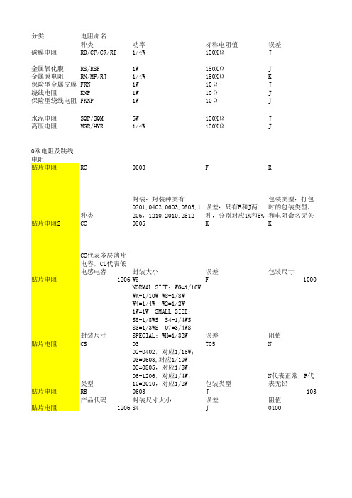
片式NTC热敏电阻器-SDNT系列
- 格式:pdf
- 大小:671.21 KB
- 文档页数:4
![SUNLORD-1[1]热敏电阻规格书](https://img.taocdn.com/s1/m/0bb12b29cfc789eb172dc8b0.png)
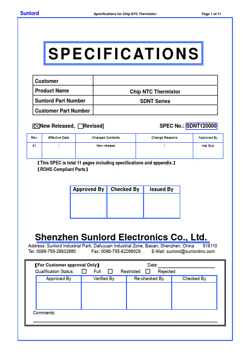
1. ScopeThis specification applies to SDNT series of chip NTC thermistors. 2.Product Description and Identification (Part Number) 1) DescriptionExample:SDNT series of multi-layer chip NTC thermistors. 2)Product Identification (Part Number)SDNT ※※※※ X ○○○ ※ □□□□ ◎ T F ① ② ③ ④ ⑤ ⑥ ⑦ ⑧ ⑨3. Electrical CharacteristicsPlease refer to Appendix A (Page 8~11).1) Operating and storage temperature range (individual chip without packing): -55℃ ~ +125℃ 2) Storage temperature range (packing conditions): -10~+40 and RH 75% (Max.)℃℃4. Shape and Dimensions1) Dimensions: See Fig.4-1 and Table 4-1. 2) Recommended PCB pattern for reflow soldering: See Fig.4-2 and Table 4-1.① Type SDNT Chip NTC Thermistor ② External Dimensions (L×W) [mm] 0603 [0201] 0.6×0.3 1005 [0402] 1.0×0.5 1608 [0603] 1.6×0.8 2012 [0805]2.0×1.25③ Internal CodeX④ Nominal Zero-Power Resistance (K Ω)Example Nominal Value 103 10 223 22 104 100⑤ Resistance Tolerance F ±1% H ±3% J ±5%K ±10% ⑦ B Constant Tolerance F ±1% H ±3% ⑥ Nominal B Constant (25 to 50)℃℃Example Nominal 3450 3450K 4250 4250K ⑧ PackagingTTape & Reel⑨ HSF ProductsHazardous Substance Free ProductsType L W T a ABC0603 [0201] 0.6±0.05 [0.024±0.002] 0.3±0.05 [0.012±0.002] 0.3±0.05 [0.012±0.002] 0.15±0.05 [0.006±0.002] 0.20~0.30 0.20~0.30 0.30~0.35 1005 [0402] 1.0±0.15 [0.039±0.006] 0.5±0.15 [0.020±0.006] 0.5±0.15 [0.020±0.006] 0.25±0.1 [0.010±0.004] 0.45~0.55 0.40~0.50 0.45~0.55 1608 [0603] 1.6±0.15 [0.063±0.006] 0.8±0.15 [0.031±0.006] 0.8±0.15 [0.031±0.006] 0.3±0.2 [0.012±0.008] 0.60~0.80 0.60~0.80 0.60~0.80 2012 [0805]2.0 ±0.2 [0.079 ±0.008]1.25±0.2 [0.049±0.008]0.85±0.2 [0.033±0.008]0.5±0.3 [0.020±0.012]0.80~ 1.200.80~ 1.200.90~ 1.60[Table 4-1] Unit: mm [inch]Fig. 4-2Fig. 4-15. Test and Measurement Procedures5.1 Test Conditions5.1.1 Unless otherwise specified, the standard atmospheric conditions for measurement/test as:20±15℃a. AmbientTemperature:b. Relative Humidity : 65±20%c. Air Pressure: 86kPa to 106kPa5.1.2 If any doubt on the results, measurements/tests should be made within the following limits:20±2℃Temperature:a. Ambientb. Relative Humidity: 65±5%c. Air Pressure: 86kPa to 106kPa5.2 Visual Examinationa. Inspection Equipment: 20× magnifier5.4 Reliability Test*1: For F and H tolerance code, the change of R25 should be within ±1% and ±3% respectively. For others, the change of R25 should be within ±5%.*2: For F code tolerance, the change of B constant should be within ±1%. For others, the change of B constant should be within ±2%.6. Packaging, Storage and Transportation6.1 Packaging6.1.1 Tape Carrier Packaging:Packaging code: Ta. Tape carrier packaging are specified in attached figure Fig.6.1-1~4b. Tape carrier packaging quantity please see the following table:Type 0603[0201] 1005[0402] 1608[0603] 2012[0805]T(mm) 0.3±0.05 0.5±0.15 0.8±0.15 0.85±0.2Tape Paper Tape Paper Tape Paper Tape Paper TapeQuantity 15K 10K 4K 4K(1). Taping Drawings (Unit: mm)Remark: The sprocket holes are to the right as the tape is pulled toward the user.(2) Taping Dimensions (Unit: mm)(3) Reel Dimensions (Unit: mm)6.2 Storagea.Package must be stored at 40 or less and 70% RH or less.℃ b. The solderability of the external electrode may be deteriorated if packages are stored where they are exposed to dust ofharmful gas (e.g. HCl, sulfurous gas of H 2S)c. Packaging material may be deform-ed if package are stored where they are exposed to heat of direct sunlight.d.Solderability specified in Clause 5.4.6 shall be guaranteed for 3 months from the date of delivery on condition that they are stored at the environment specified in Clause 3 .For those parts, which passed more than 3 months shall be checked solder-ability before use.7. RecommendedSoldering Technologies7.1 Re-flowing Profile:△ Preheat condition: 150 ~200/60~120℃sec. △ Allowed time above 217℃: 60~90sec. △ Max temp: 260℃△ Max time at max temp: 10sec. △ Solder paste: Sn/3.0Ag/0.5Cu △ Allowed Reflow time: 2x maxType A B P Tmax 0603[0201]0.40±0.10.70±0.1 2.0±0.05 0.55 1005[0402]0.65±0.11.15±0.12.0±0.05 0.8Fig. 6.1-410.0±1.5mm4.3±0.2mm4.0±0.1mm5.0±0.1mmType A B P Tmax 1608[0603] 1.0±0.2 1.8±0.2 4.0±0.1 1.1 2012[0805]1.5±0.22.3±0.2 4.0±0.1 1.1Chip CavityDirection of FeedChip CavityDirection of FeedFig 6.1-2[Note: The reflow profile in the above table is only for qualification and is not meant to specify board assembly profiles. Actual board assembly profiles must be based on the customer's specific board design, solder paste and process, and should not exceed the parameters as theReflow profile shows.]26015020021725℃7.2 Iron Soldering Profile.△ Iron soldering power: Max.30W △ Pre-heating: 150 / 60 sec. ℃ △ Soldering Tip temperature: 350Max.℃ △ Soldering time: 3 sec Max. △ Solder paste: Sn/3.0Ag/0.5Cu △ Max.1 times for iron soldering[Note: Take care not to apply the tip of the soldering iron to the terminal electrodes.]8. Supplier Informationa) Supplier:Shenzhen Sunlord Electronics Co., Ltd. b) Manufacturer:Shenzhen Sunlord Electronics Co., Ltd. c) Manufacturing Address:Sunlord Industrial Park, Dafuyuan Industrial Zone, Guanlan, Shenzhen, China Zip: 518110Tc ℃350℃Appendix A: Electrical Characteristics I.SDNT0603 SeriesII. SDNT1005 SeriesPart NumberResistance at 25℃R25 (k Ω)B constant (25-50) (K)℃Max. PermissiveOperating Current (25℃)(mA)Thermal Time ConstantDissipation Factor (mW/)℃ Rated Electric Power (mW)SDNT0603X103□3380◎TF 10 3380 0.31 SDNT0603X683□4150◎TF 68 4150 0.11 SDNT0603X104□4150◎TF 100 4150 0.10<3sec 1.0 100Part NumberResistance at 25℃R25 (k Ω)B constant (25-50) (K)℃Max. PermissiveOperating Current (25℃)(mA)Thermal Time ConstantDissipation Factor (mW/)℃ Rated ElectricPower (mW)SDNT1005X220□3380◎TF 0.022 3380 6.7 SDNT1005X400□3380◎TF 0.040 3380 5.0 SDNT1005X101□3380◎TF 0.10 3380 3.1 SDNT1005X151□3380◎TF 0.15 3380 2.5 SDNT1005X221□3450◎TF 0.22 3450 2.1 SDNT1005X331□3450◎TF 0.33 3450 1.7 SDNT1005X471□3450◎TF 0.47 3450 1.4 SDNT1005X681□3450◎TF 0.68 3450 1.2 SDNT1005X102□3450◎TF 1.0 3450 1.0 SDNT1005X152□3950◎TF 1.5 3950 0.81 SDNT1005X222□3950◎TF 2.2 3950 0.67 SDNT1005X332□3950◎TF 3.3 3950 0.55 SDNT1005X472□3950◎TF 4.7 3950 0.46 SDNT1005X682□3950◎TF 6.8 3950 0.38 SDNT1005X103□3380◎TF 10 3380 0.31 SDNT1005X103□3950◎TF 10 3950 0.33 SDNT1005X103□4050◎TF 10 4050 0.33 SDNT1005X153□3450◎TF 15 3450 0.25 SDNT1005X223□3950◎TF 22 3950 0.23 SDNT1005X333□3500◎TF 33 3500 0.14 SDNT1005X473□4100◎TF 47 4100 0.12 SDNT1005X503□4100◎TF 50 4100 0.12 SDNT1005X683□4150◎TF 68 4150 0.11 SDNT1005X104□4150◎TF 100 4150 0.10 SDNT1005X104□4250◎TF 100 4250 0.10 SDNT1005X154□4150◎TF 150 4150 0.08 SDNT1005X224□4250◎TF 220 4250 0.06 SDNT1005X334□4300◎TF 330 4300 0.05 SDNT1005X474□4350◎TF 470 4350 0.04 SDNT1005X684□4400◎TF 680 4400 0.03 <3sec 1.0 100III. SDNT1608 Series . SDNT2012 SeriesPart Number Resistance at 25℃R25 (kΩ)B constant(25-50℃) (K)Max. PermissiveOperatingCurrent (25℃)(mA)Thermal TimeConstantDissipationFactor(mW/℃)RatedElectricPower(mW)SDNT2012X101□3380◎TF 0.10 3380 4.0 SDNT2012X151□3380◎TF 0.15 3380 3.5 SDNT2012X221□3450◎TF 0.22 3450 3.0SDNT2012X331□3450◎TF 0.33 3450 2.5 SDNT2012X471□3450◎TF 0.47 3450 2.0 SDNT2012X681□3450◎TF 0.68 3450 1.7 SDNT2012X102□3450◎TF 1.0 3450 1.4 <5sec 2.0 200Part Number Resistance at 25℃R25 (kΩ)B constant(25-50) (K)℃Max. PermissiveOperatingCurrent (25℃)(mA)Thermal TimeConstantDissipationFactor(mW/)℃Rated ElectricPower (mW)SDNT1608X101□3380◎TF 0.10 3380 3.1SDNT1608X151□3380◎TF 0.15 3380 2.5SDNT1608X221□3450◎TF 0.22 3450 2.1SDNT1608X331□3450◎TF 0.33 3450 1.7SDNT1608X471□3450◎TFTF 0.47 3450 1.4SDNT1608X681□3450◎TF 0.68 3450 1.2SDNT1608X102□3450◎TF 1.0 3450 1.0SDNT1608X152□3450◎TF 1.5 3450 0.81SDNT1608X222□3950◎TF 2.2 3950 0.67SDNT1608X302□3950◎TF 3.0 3950 0.55SDNT1608X332□3950◎TF 3.3 3950 0.55SDNT1608X472□3500◎TF 4.7 3500 0.44SDNT1608X472□3950◎TF 4.7 3950 0.46SDNT1608X502□3950◎TF 5.0 3950 0.44SDNT1608X682□3950◎TF 6.8 3950 0.38SDNT1608X103□3450◎TF 10 3450 0.31SDNT1608X103□3950◎TF 10 3950 0.33SDNT1608X153□3950◎TF 15 3950 0.25SDNT1608X223□4050◎TF 22 4050 0.21SDNT1608X333□4050◎TF 33 4050 0.17SDNT1608X473□4150◎TF 47 4150 0.14SDNT1608X503□4150◎TF 50 4150 0.13SDNT1608X683□4150◎TF 68 4150 0.12SDNT1608X104□4250◎TF 100 4250 0.10SDNT1608X154□4300◎TF 150 4300 0.08SDNT1608X224□4350◎TF 220 4350 0.06SDNT1608X334□4400◎TF 330 4400 0.05SDNT1608X474□4500◎TF 470 4500 0.04SDNT1608X684□4500◎TF 680 4500 0.03SDNT1608X135□4700◎TF 1300 4700 0.02<5sec 1.0 100Part NumberResistance at 25℃R25 (k Ω)B constant (25-50℃) (K)Max. PermissiveOperating Current (25℃)(mA)Thermal Time ConstantDissipation Factor (mW/℃)Rated Electric Power (mW)SDNT2012X152□3950◎TF 1.5 3950 1.2 SDNT2012X202□3950◎TF 2.0 3950 1.0 SDNT2012X222□3950◎TF 2.2 3950 0.90 SDNT2012X332□3950◎TF 3.3 3950 0.72 SDNT2012X472□3950◎TF 4.7 3950 0.65 SDNT2012X502□3950◎TF 5.0 3950 0.60 SDNT2012X682□3950◎TF 6.8 39500.50 SDNT2012X103□3450◎TF 10 3450 0.40 SDNT2012X103□3950◎TF 10 3950 0.44 SDNT2012X153□3500◎TF 15 3500 0.32 SDNT2012X223□4050◎TF 22 4050 0.31 SDNT2012X333□4050◎TF 33 4050 0.24 SDNT2012X473□4150◎TF 47 4150 0.20 SDNT2012X503□4150◎TF 50 4150 0.18 SDNT2012X683□4150◎TF 68 4150 0.16 SDNT2012X104□4250◎TF 100 4250 0.14 SDNT2012X154□4300◎TF 150 4300 0.11 SDNT2012X224□4350◎TF 220 4350 0.08 SDNT2012X334□4400◎TF 330 4400 0.06 SDNT2012X474□4500◎TF 470 4500 0.05 SDNT2012X684□4500◎TF 680 4500 0.04 SDNT2012X135□4700◎TF 1300 4700 0.03<5sec 2.0 200※□: Please specify the tolerance code of R25 (F=±1%, H=±3%, J=±5%, K=±10%). ※◎: Please specify the tolerance code of B value (F=±1%, H=±3%). TYPICAL ELECTRICAL CHARACTERISTICSSunlord Specifications for Chip NTC Thermistor Page 11 of 11。


片式ntc热敏电阻
片式NTC热敏电阻是一种常用的温度传感器,它由一块热敏电阻片和两个电极组成。
这种电阻片的电阻值随着温度的变化而变化,因此它可以用来测量温度。
片式NTC热敏电阻的优点是尺寸小、响应速度快、精度高、可靠性好、价格低廉等。
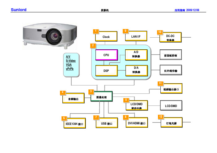
它常被应用于家电、汽车、电子设备等领域中的温度测量和控制。
在使用片式NTC热敏电阻时,需要注意其温度范围和阻值范围。
不同型号的片式NTC热敏电阻适用于不同的温度范围和阻值范围。
因此,在使用前需要了解其具体参数,并根据实际需求进行选择。
总之,片式NTC热敏电阻是一种非常实用的温度传感器,具有尺寸小、响应速度快、精度高等优点,可以广泛应用于各种领域的温度测量和控制。
- 1 -。