半导体集成电路RD19230型轴角-数字转换电路使用说明书
- 格式:pdf
- 大小:263.21 KB
- 文档页数:13

![l293d集成电路说明[整理版]](https://uimg.taocdn.com/4610051f591b6bd97f192279168884868662b840.webp)
L293D采用16引脚DIP封装,其内部集成了双极型H-桥电路,所有的开量都做成n型。
这种双极型脉冲调宽方式具有很多优点,如电流连续;电机可四角限运行;电机停止时有微振电流,起到“动力润滑”作用,消除正反向时的静摩擦死区:低速平稳性好等。
L293D通过内部逻辑生成使能信号。
H-桥电路的输入量可以用来设置马达转动方向,使能信号可以用于脉宽调整(PWM)。
另外,L293D 将2个H-桥电路集成到1片芯片上,这就意味着用1片芯片可以同时控制2个电机。
每1个电机需要3个控制信号EN12、IN1、IN2,其中EN12是使能信号,IN1、IN2为电机转动方向控制信号,IN1、IN2分别为1,0时,电机正转,反之,电机反转。
选用一路PWM连接EN12引脚,通过调整PWM的占空比可以调整电机的转速。
选择一路I/O口,经反向器74HC14分别接IN1和IN2引脚,控制电机的正反转L293D集成电路说明L293DPUSH-PULL FOUR CHANNEL DRIVER WITH DIODES推拉4通道驱动带二极管600mA. OUTPUT CURRENT CAPABILITY PER CHANNEL600mA输出电流每通道1.2A PEAK OUTPUT CURRENT (NON REPETITIVE) PER CHANNEL1.2A峰值输出电流每通道(不可重复,估计将会损坏)ENABLE FACILITY使用简易OVERTEMPERATURE PROTECTION温度过高保护LOGICAL ”0” INPUT VOLTAGE UP TO 1.5v(HIGH NOISE IMMUNITY逻辑"0"输入电压为1.5V,可以免除1.5V以下的干扰INTERNAL CLAMPS DIODES内置钳位二极管DESCRIPTION描述The L293D is a m onolithic integrated high voltage,high current four channel vriver designed to acceptstandard DTL or TTL logic levels and drive induc-tiveloads (such as relays solenoides, DC andstepping motors) and switching power transistors.L293D 是单块集成电路,高电压,高电流,四通道驱动,设计用来接受DTL或者TTL逻辑电平,驱动感性负载(比如继电器,直流和步近马达),和开关电源晶体管。

功率器件产品手册翠展微电子2021公司介绍翠展微电子成立于2018年5月,公司位于中国上海张江综合性国家科学中心的张江集成电路产业区内,工厂位于浙江省嘉善县经济技术开发区。
作为一家中国本土的汽车级功率器件与模拟集成电路设计销售公司,公司立志打破进口垄断,实现进口替代,将翠展微电子打造成为新能源汽车半导体行业的中国品牌领军企业。
公司将聚焦中国新能源汽车行业的挑战和压力,提供有竞争力的半导体产品和服务,持续为新能源汽车客户创造价值。
公司团队由多名业内资深人员构成,成员具有平均15年国际汽车半导体公司及汽车电子行业的销售、应用、方案设计及设计研发经验,在汽车级功率器件与集成电路产品领域具有雄厚的研发实力和销售渠道。
我们有一支专业、坚韧、有活力的人才队伍,坚持以技术为导向,为客户提供个性化、系统级的产品与技术咨询服务,致力于提供优良的技术服务和高性价比的产品,驱动中国汽车电子产业快速蓬勃发展,共筑中国芯,中国梦!IGBT模块产品IGBT ModuleIGBT模块产品性能对比Grecon IGBT Module vs Competitor沟槽删MOSFET < 250VTrench MOSFETNormal RDSONNormal SW SpeedNormal SOA/EAS分裂删型沟槽MOSFET < 250VSplit Gate Trench MOSFETSmallest RDSONFast SW SpeedWeek SOA/EAS翠展集成散热水道IGBT 模块的优点:1. 不需要铜底板,减小热阻2. 不需要导热硅脂,减小热阻,提高系统寿命和可靠性,并减少了生产工序。
3. 电机控制器壳体上不需要加工散热水道,结构更加简单,更易加工和装配。
IGBT 模块定制产品,集成散热水道的IGBT 模块---工程样品常规IGBT 模块常规IGBT 模块翠展集成散热水道的IGBT 模块用常规IGBT 模块的电机控制器用翠展集成散热水道IGBT 模块的电机控制器IGBT 单管产品 IGBT discretePTC 典型应用电路点火IGBT 典型应用/上海上海市浦东新区祖冲之路2305号B 幢515室电话:************苏州江苏省苏州市工业园区金鸡湖大道1355号国际科技园二期A203-5嘉善浙江省嘉兴市嘉善县滨江路6号2幢电话:*************联系我们Contact us。
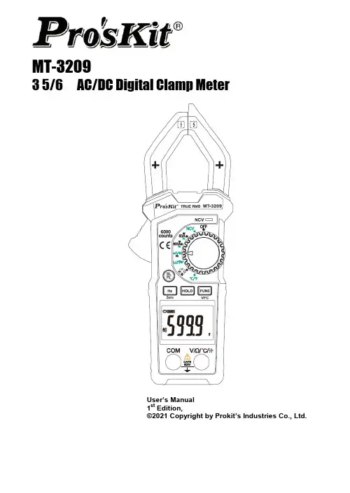
MT-32093 5/6 AC/DC Digital Clamp MeterUser’s Manual1st Edition,©2021 Copyright by Prokit’s Industries Co., Ltd.1.Safety InformationSpecial attention shall be paid when using the meter, improper use might cause an electric shock or damage the meter. General safety procedures shall be followed during the use and safety measuring methods regulated by the instruction manual shall be completely respected.To fully make use of the functions of the meter and ensure safe operation, please carefully read and follow the use method of this manual.The meter meets IEC-61010-1, IEC-61010-2-030, IEC-61010-2-032)Safety Requirements for Electronic Measuring Instruments of the secondary pollution.over-voltage standard is CATⅡ600V.Please follow the safe operation guidance and ensure to use the meter in safe.⏹1.1 PreparationsWhen use the meter, users must comply with the standard safety rules: - General protection against electric shock- Prevent misuse of the meterAfter receiving the meter, check if it has been damaged during the delivery.After been kept and delivered in shoddy condition, check and confirm if the meter is damaged or not.The test lead must be in good condition. Before use, check the test lead to see if any damage causes to the insulation or if the metal wire of the cable is bare.Note (important security information, see the Instruction Manual)It can be used on hazardous live conductors.Double insulation protection (Category II)Grounding⏹1.3 MaintenancePlease do not attempt to open the bottom case to adjust or repair the meter; such operation could only be performed by technicians fully aware of the meter and the risk of electric shock.Before opening the meter case or battery cover at the end, the test lead should be removed from the circuit being measured.the battery should be replaced immediately.Use a damp cloth and mild detergent to clean the meter; do not use abrasive cleaning agents or solvents.Power supply of the meter should be turned off when not in use, range switch to the OFF position.If the meter is not used for a long time, batteries should be removed to prevent damage to the meter.2. Descriptions⏹ 2.1 Part Name① Non-contact voltage detection sensing area② Non-contact voltage warning LED ③ Rotary switch ④ Function selection key⑤ Data hold key⑥ Display screen⑦ Input socket⑧ Frequency key⑨ Back light & Flash light key ⑩ Trigger⑪ Current clamp head: Used for measuring current ⏹ 2.2 LCD Display Unit④ ③①② ⑤ ⑥ ⑦⑧ ⑨ ⑩ ⑪DC AC DC, AC voltage or AmpereConnected / Disconnect indicationLow batteryAutomatic shutdown indicationAutomatic range measurement modeData hold status3.SpecificationsThe meter should specify one year as a cycle to re-calibrate in the conditions of 18℃ ~28℃ and relative humidity less than 75%.⏹3.1 OverviewAutomatically select measurement function and range.Overload protection for the whole measurement range.Maximum allowable voltage between the measuring terminal and the Earth: 600V DC or 600V ACWork height: maximum 2000mDisplay: LCDMaximum display value: 6000 digits.Max open jaw: 30mm.Polar indication: Automatically indicates ‘-’ means negative polarity.Over range indication: ‘0.L’ or ‘-0.L’.Sampling time: About 3 times/sAutomatic power off time: 15 minutesPower supply: 1.5V AAA battery ×2Battery low voltage indication: LCD display symbol. Temperature coefficient: < 0.1×Accuracy/℃Working temperature: 18℃ ~28℃Storage temperature: -10℃ ~50℃⏹3.2 Technical IndexFrequency response: 40Hz-1KHz True-RMSOverload protection: 250V DC or AC (valid value)Overload protection: 250V DC or AC (valid value)Input impedance: 10MΩMaximum input voltage: 600V DCInput impedance: 10MΩMaximum input voltage: 600V AC (valid value)Frequency response: 40Hz-1kHz True-RMSInput impedance: 1MΩMaximum input voltage: 600V DC or AC (valid value).Frequency response: ACV 40Hz-1KHz; sine wave average response. FrequencyInput signal range: 0.6V~600VOverload protection: 600V DC or AC (valid value)Input signal range: 6A~600A AC current (valid value)Overload protection: 250V DC or AC (valid value)Overload protection: 250V DC or AC (valid value)forward voltage drop.The buzzer beeps when the resistance is less than 30 Overload protection: 250V DC or AC (valid value)Overload protection: 250V DC or AC (valid value)4.Operation Guide4.1 Measurement PreparationsTurn the transfer switch to the desired measurement position, turn on the power. If the battery voltage is low (of about ≤2.4V), the LCD will show“”symbol, then the battery shall be replaced.4.2 Readings HoldDuring the measuring process, if the readings are required to hold, press “Hold“ key ,the display value will be locked, press “Hold“ key again to cancel readings hold.4.3 Back Light & Flash Light1)In the process of measurement, if the ambient light is too dim, causing reading difficulties, press “ BL / FL“ key to open Back Light and it will automatically off after about 30 seconds, or press “ BL / FL“ key again to close Black Light.2)Press “ BL / FL“ key for about 2s, to turn on the flash light function and the backlight at the same time. Short press the“ BL / FL“k ey again to turn off the function. It turns off automatically with no operation for 30 seconds, the Back Light will be turned off.4.4 Auto Power Off1)If after 15 minutes when the meter is on without any operation, it will go into hibernation and automatically shut down to save power. Before the meter off, there will be sound “di-di-di” of the buzzer to remind.2)Press any key after auto power off to wake the meter into working status.4.5 AC or DC Current Measurement1)Turn the rotary switch to the appropriate position 60A or 600A.2)P ress “FUNC” to choose the ACA or DCA.3)Hold the trigger, open the clamp head and clamp one cable of the measured circuit. 4)When measured signal >0.05A, the LCD of the meter displays the measured current value.Note:⏹Clamp two lines of the measured circuit or more at the same time will not obtaincorrect measurement results.⏹To obtain accurate readings, try to enable the measured cable in the middle positionof the current clamp.⏹If you haven't measured yet, there is a display number at the DCA position on theLCD screen; press “Hz/Zero” key to clear.⏹If you measure the AC current from the VFC (Variable-frequency converter) power,press “FUNC /VFC”key for about 2 seconds to turn on the VFC currentmeasurement.1)Turn the transfer switch to the NCV position,2)Put the clamp NCV sensor square close to the measuredcable, the meter could detect if the measured cable is >90VAC voltage or not. When the meter detects AC voltage, themeter buzzer alarms and the NCV LED flashes.Note:⏹Even there is no alarm indication, the voltage might still exist. Do not judge if thereexist voltage or not in the cable relying on non-contact voltage detector. The detectionoperation might be affected by various factors, such as the socket design, differentinsulation thickness types, so on.⏹In NCV detection mode, the meter will not measure the voltage, resistance andcurrent at the same time.600V. AC voltage measuring ranges: 6V, 60V and 600V.Measurement DC of voltage or AC voltage1)Turn the rotary switch to the position “V”and press “FUNC” to choose DCV or ACV.2)Connect the test leads to COM input socket and V/Ω input socket respectively.3)Use another two ends of the test leads to measure the voltage of the circuit to be measured. (In parallel connection with the circuit to be measured.)4)Read the measured voltage value on LCD screen. When DC voltage measurement is attempted, the display unit will show the voltage polarity of the circuit connected to the lead-shaped meter in red.Notes:⏹Within the measuring range of DC or AC voltage, even if there is no input or noconnection to the test lead, the meter will display some information. In this situation, press short circuit “V” and “COM” terminal to reset the meter to zero.⏹The value of the AC voltage measured with this meter is True RMS (root meansquare). These measurements are accurate for sine wave and other waves (without DC offset), square wave, triangular wave and step wave.⏹If you measure the AC voltage from the VFC (Variable-frequency converter) power,press the “FUNC /VFC” key for about 2s to turn on the VFC voltage measurement. 4.8 LoZ Volts (DC or AC voltage) MeasurementLow impedance voltage measurement function to eliminate false voltage. This meter automatic identified of DC voltage and AC voltage.The meter provides DC or AC voltage measuring ranges 600V.1)Turn the rotary switch to the LoZ V.2)Connect the test leads to COM input socket and V/Ω input socket respectively.3)Use another two ends of the test lead to measure the voltage of the circuit to be measured. (In parallel connection with the circuit to be measured.)4)Read the measured voltage value on LCD screen. When DC voltage measurement is attempted, the display unit will show the voltage polarity of the circuit connected to the lead-shaped meter in red.4.9 Frequency MeasurementPass V position:1)Turn the switch to “V” and press “FUNC” to choose ACV, and then press “Hz” to choose Hz.2)Connect the black test lead to the COM jack and the red lead to the V/Ω jack.3)Measure the frequency value of the circuit under test with the other two ends of the test leads and “Hz” the measured value on LCD screen.Pass AC A position(The signal current must be ≥6A):1)Turn the rotary switch to the appropriate position 60A or 600A, then press the “Hz”key to choose Hz .2)Hold the trigger, open the clamp head and clamp one cable of the measured circuit.3)When measured signal ≥6A AC current, the LCD of the meter displays the measured Hz value.4.10 Resistance MeasurementOhm is the unit of electric resistance (Ω).The measuring ranges of electric resistance of this meter are 600Ω, 6kΩ, 60kΩ, 600kΩ, 6MΩ and 60MΩ,Measurement of electric resistance1)Turn the rotary switch to the Ωposition, press “FUNC” to choose Ω.2)Connect the test leads to COM input socket and V/Ω input socket respectively.3)Use another two ends of the test lead to measure the electric resistance of the circuit to be measured.4)Read the measured electric resistance value on LCD screen.Notes:⏹The measured value of the electric resistance of the circuit differs a bit from the ratedvalue of the electric resistance.⏹To ensure measurement accuracy, in attempting a low resistance measurement, firstput two lead-shaped meters in short circuit and capture the resistance reading of these short circuits. Then subtract the aforesaid reading from the measured resistance.⏹When the meter is in open circuit, the display unit will show “O.L” that indicates themeasured value is over the measuring range.4.11 Diode test1)Turn the rotary switch to the Ωposition and press “FUNC” to choose .2)Connect the test leads to COM input socket and V/Ω input socket respectively.3)Connect the test leads to the positive and negative poles of the diode to be tested respectively.4)The meter displays the forward bias value of the diode to be tested. If the polarity of the test lead is reversed, the meter will display “O.L”.4.12 Beep Continuity Test1)Turn the rotary switch to the Ωposition and press “FUNC” to choose.2)Connect the test leads in black and in red to COM input socket and V/Ω input socket respectively.3)Use another two ends of the test lead to measure the resistance of the circuit to be measured. If the measured distance is less than 30Ω, the beeper will sound continuously, and the LED will be on.4.13 Capacitance MeasurementThe measuring ranges for the capacitance of this meter are 6nF/60nF/600nF/6μF/60μF/600μF/6mF/100mF.Measurement of capacitance:1)Turn the rotary switch to the Ωposition, press “FUNC” to choose.2)Connect the test leads to COM input socket and V/Ωinput socket respectively. 3)Use another two ends of the test lead to measure the capacitance of the capacitor to be measured, and capture the measured value on LCD screen.Note:⏹The measurement of a large capacitance requires a given period of stabilization ofreading.⏹To avoid damage to the meter, the measurement of a capacitor with polaritiesrequires much attention to its polarity.4.14 Temperature Measurement1)Turn the rotary switch to the ℃/℉, press the “FUNC” to choose ℃or ℉.2)Insert the red plug of the thermocouple into the end of V/Ω℃, and insert the black plug of the thermocouple into COM socket.3)Place the temperature probe on the object being measured, and temperature the measured value on LCD screen.5.Maintenance5.1 Replace BatteryBefore opening the battery cover of the meter, the test lead shall be moved from the measuring circuit first to prevent the risk of electric shock.1)If “” symbol appears, it means the battery shall be replaced.2)Loosen the screws of the battery cover to move it away.3)Replace the battery with new one.4)Put back the battery cover.Note:Do not violate the battery polarity.5.2Replace Test LeadsWhen replacing the test lead, the new ones shall be of the same or in equal level. The test lead shall be in good condition, test lead level: 1000V 10A. If the insulation layer of the test lead is damaged, such as the metal wire of the cable isexposed, then it shall be replaced.6.Accessories1.Operation Manual X 1 3. K-Type thermocouple X 12.Test lead X 1 pairMT-3209 鉗形電錶使用說明書1.聲明根據國際版權法,未經允許和書面同意,不得以任何形式(包括存儲和檢索或翻譯為其他國家或地區語言)複製本說明書的任何內容。
TEA2209T有源桥式整流器控制器第1.1版——2021年5月7日产品数据手册1 总述TEA2209T是新一代有源桥式整流器控制器产品,旨在替代传统的二极管桥。
将TEA2209T与低电阻高压外部MOSFET配合使用,可消除典型整流器二极管正向传导损耗,从而显著提高功率转换器的效率。
在90 V(AC)电源电压下,效率可以提高约1.4%。
TEA2209T采用绝缘硅片(SOI)工艺设计。
2 特性和优势2.1 能效特性•消除了二极管整流器桥的正向传导损耗•极低IC功耗(2 mW)2.2 应用特性•集成高压电平转换器•直接驱动所有四个整流器MOSFET•外部零件数量很少•集成X电容放电(2 mA)•自供电•全波驱动可改善总谐波失真(THD)•S016封装2.3 控制特性•用于所有外部功率MOSFET的禁用功能•用于高端和低端驱动器的欠压锁定(UVLO)•用于所有外部功率MOSFET的漏源过压保护•用于所有外部功率MOSFET的启动时栅极下拉电流3 应用TEA2209T面向将升压型功率因数控制器作为第一级的电源。
第二级可以是谐振控制器、反激控制器或任何其他控制器拓扑。
它可用于所有需要高效率的电源:•电源适配器•台式电脑和一体机电源•电视电源•服务器电源4 订购信息表1.订购信息型号封装名称说明版本TEA2209T/1 SO16 塑料小型封装;16引脚;体宽3.9 mm SOT109-15 标示表2.标示型号标记代码TEA2209T/1 TEA2209T6 功能框图VCC VRVCCHL GATEHLL GATELL COMPVCCHRGATEHRRGATELRVCCVCC电平转换电平转换CONTROLVR电源+X电容放电1.3 V图1.功能框图COMP_POL GND7 引脚配置信息7.1 引脚配置7.2 引脚说明表3.引脚说明符号引脚说明L 1 左输入,左上方MOSFET的源极VCCHL 2 左侧高端浮动电源GATEHL 3 左侧高端栅极驱动器HVS 4 高压隔离间隔;不连接GATELL 5 左侧低端栅极驱动器VCC 6 电源电压GND 7 接地COMP_POL 8 比较器极性设置COMP 9 比较器输入GATELR 10 右侧低端栅极驱动器HVS 11 高压隔离间隔;不连接R 12 右输入,右上方MOSFET的源极VCCHR 13 右侧高端浮动电源GATEHR 14 右侧高端栅极驱动器HVS 15 高压隔离间隔;不连接VR 16 整流电源电压L VCCHLGATEHLHVSGATELLVCCGND COMP_POLVRHVSGATEHRVCCHRRHVSGATELRCOMP IC图2.引脚结构图(SOT109-1)8 功能说明8.1简介TEA2209T 是用于有源桥式整流器的控制器IC 。

显示号 数据内容 标识编码 上1月历史电量数据块 26字节 D120H上2月历史电量数据块 26字节 D121H上3月历史电量数据块 26字节 D122H上4月历史电量数据块 26字节 D123H上5月历史电量数据块 26字节 D124H上6月历史电量数据块 26字节 D125H上7月历史电量数据块 26字节 D126H上8月历史电量数据块 26字节 D127H上9月历史电量数据块 26字节 D128H上10月历史电量数据块 26字节 D129H上11月历史电量数据块 26字节 D12AH上12月历史电量数据块 26字节 D12BH陕西西仪电子集团有限公司Shanxiyi dianzi jituanCo.,Ltd.地址:西安市航天科技园2-11电话:************传真:4006981163-1819627 DSSD256三相电子式多功能电能表产品使用说明书陕西西仪电子集团有限公司目 录1. 概述 (2)1.1 产品特点及用途 (2)1.2 产品标准 (2)1.3 规格型号 (2)1.4 系列产品功能列表 (2)2 工作原理及外形特征 (4)2.1 工作原理 (4)2.2 外形图 (4)3 技术指标 (4)4 安装和接线 (5)4.1 电表安装 (5)4.2 电源端子接线 (5)4.3 功能端子接线 (6)4.4 脉冲输出端子接线 (6)4.5 通讯接口 (7)5 功能及使用 (7)5.1 电能计量功能 (7)5.2 最大需量功能 (7)5.3 复费率功能 (7)5.4 事件记录功能 (7)5.5 电能冻结及负荷记录功能 (8)5.6 数据显示功能 (8)5.7 设置功能 (10)5.8 其他功能 (11)6 常见故障问题解答 (12)7 运输和储存 (12)售后服务 (12)结束语 (12)附录A 内部参数及状态(控制)字说明 (13)附录B 功能附录表 (15)1显示号 数据内容 标识编码 876 第四节假日时段表 MM.DD.NN C414H 877 第五节假日时段表 MM.DD.NN C415H 878 第六节假日时段表 MM.DD.NN C416H 879 第七节假日时段表 MM.DD.NN C417H 880 第八节假日时段表 MM.DD.NN C418H负荷曲线记录1 75字节 D210H负荷曲线记录2 75字节 D211H负荷曲线记录3 75字节 D212H负荷曲线记录4 75字节 D213H负荷曲线记录5 75字节 D214H负荷曲线记录6 75字节 D215H负荷曲线记录7 75字节 D216H负荷曲线记录8 75字节 D217H负荷曲线记录9 75字节 D218H负荷曲线记录10 75字节 D219H负荷曲线记录11 75字节 D220H负荷曲线记录12 75字节 D221H负荷曲线记录13 75字节 D222H负荷曲线记录14 75字节 D223H负荷曲线记录15 75字节 D224H负荷曲线记录16 75字节 D225H负荷曲线记录17 75字节 D226H负荷曲线记录18 75字节 D227H负荷曲线记录19 75字节 D228H负荷曲线记录20 75字节 D229H负荷曲线记录21 75字节 D230H负荷曲线记录22 75字节 D231H负荷曲线记录23 75字节 D232H负荷曲线记录24 75字节 D233H负荷曲线记录25 75字节 D234H负荷曲线记录26 75字节 D235H负荷曲线记录27 75字节 D236H负荷曲线记录28 75字节 D237H负荷曲线记录29 75字节 D238H负荷曲线记录30 75字节 D239H负荷曲线记录31 75字节 D240H负荷曲线记录32 75字节 D241H负荷曲线记录33 75字节 D242H负荷曲线记录34 75字节 D243H负荷曲线记录35 75字节 D244H负荷曲线记录36 75字节 D245H26显示号 数据内容 标识编码 823 第2日时段表第3时段起始时间及费率号 HHmmNN C343H 824 第2日时段表第4时段起始时间及费率号 HHmmNN C344H 825 第2日时段表第5时段起始时间及费率号 HHmmNN C345H 826 第2日时段表第6时段起始时间及费率号 HHmmNN C346H 827 第2日时段表第7时段起始时间及费率号 HHmmNN C347H 828 第2日时段表第8时段起始时间及费率号 HHmmNN C348H 829 第2日时段表第9时段起始时间及费率号 HHmmNN C349H 830 第2日时段表第10时段起始时间及费率号 HHmmNN C34AH834 第3日时段表第1时段起始时间及费率号 HHmmNN C351H 835 第3日时段表第2时段起始时间及费率号 HHmmNN C352H 836 第3日时段表第3时段起始时间及费率号 HHmmNN C353H 837 第3日时段表第4时段起始时间及费率号 HHmmNN C354H 838 第3日时段表第5时段起始时间及费率号 HHmmNN C355H 839 第3日时段表第6时段起始时间及费率号 HHmmNN C356H 840 第3日时段表第7时段起始时间及费率号 HHmmNN C357H 841 第3日时段表第8时段起始时间及费率号 HHmmNN C358H 842 第3日时段表第9时段起始时间及费率号 HHmmNN C359H 843 第3日时段表第10时段起始时间及费率号 HHmmNN C35AH847 第4日时段表第1时段起始时间及费率号 HHmmNN C361H 848 第4日时段表第2时段起始时间及费率号 HHmmNN C362H 849 第4日时段表第3时段起始时间及费率号 HHmmNN C363H 850 第4日时段表第4时段起始时间及费率号 HHmmNN C364H 851 第4日时段表第5时段起始时间及费率号 HHmmNN C365H 852 第4日时段表第6时段起始时间及费率号 HHmmNN C366H 853 第4日时段表第7时段起始时间及费率号 HHmmNN C367H 854 第4日时段表第8时段起始时间及费率号 HHmmNN C368H 855 第4日时段表第9时段起始时间及费率号 HHmmNN C369H 856 第4日时段表第10时段起始时间及费率号 HHmmNN C36AH 860 第5日时段表第1时段起始时间及费率号 HHmmNN C371H 861 第5日时段表第2时段起始时间及费率号 HHmmNN C372H 862 第5日时段表第3时段起始时间及费率号 HHmmNN C373H 863 第5日时段表第4时段起始时间及费率号 HHmmNN C374H 864 第5日时段表第5时段起始时间及费率号 HHmmNN C375H 865 第5日时段表第6时段起始时间及费率号 HHmmNN C376H 866 第5日时段表第7时段起始时间及费率号 HHmmNN C377H 867 第5日时段表第8时段起始时间及费率号 HHmmNN C378H 868 第5日时段表第9时段起始时间及费率号 HHmmNN C379H 869 第5日时段表第10时段起始时间及费率号 HHmmNN C37AH873 第一节假日时段表 MM.DD.NN C411H874 第二节假日时段表 MM.DD.NN C412H875 第三节假日时段表 MM.DD.NN C413H251 概 述1.1 产品特点及用途DSSD/DTSD型三相电子式多功能电能表是采用先进的电能计量专用芯片,将有功、无功计量与成熟的多费率技术相结合设计而成,应用数字采样处理技术及SMT工艺,根据中国实际用电状况所设计、制造的具有国际先进水平的电能仪表。
日本SHIMADEN(岛电)FP23可编程PID调节器中文操作说明一.日本岛电公司型FP230。
1%高精度高分辨率完全自由输入20组曲线(共400步)可编程单双通道,大液晶双排LED5位醒目显示,多DI/DO接口,常用通讯及MODBUS协议,支持用户灵活方便编译的计算机USB接口软硬件,功能极大集成。
可广泛用于半导体制造,计量仪表,传感器标定,航空航天,石油化工,冶金等自控领域二.仪表的显示面板和功能键∶调节输出2两个工作点:红外线通讯收发。
前面板按键开关:∶用于选择八个命令组窗口群;请尊敬的用户在使用前确认FP23的选型型号与系统要求无误。
三.选择FP23规格,设定FP23工作模式用户可根据实际需求,选择单输入或双输入两种规格之一。
选择单输入规格有下面两种工作模式∶SS模式∶单路输入,单路调节输出;SD模式∶单路输入,双路调节输出。
选择双输入规格有下面四种工作模式∶DL模式∶双路输入,独立两通道调节;DS模式∶双路输入,单路输出调节;DD模式∶双路输入,双路输出调节。
四.单通道FP23加热系统的定值控制快速设定例调节器选定型号为:FP23-SSPN-0000000系统要求:烘箱加热器K型热电偶0.0—800.0℃,固态继电器输出设定值为600.0℃,EV1事件输出为上限绝对值报警,报警值为700.0℃。
具体设置如下:1.在UNIT/RANGE【7-3】窗口依次设定量程RANG:06(0.0—800.0℃)单位UNIT:℃在该窗口改变量程后,用户退出该窗口群时调节器会出现此画面,让用户确认。
将NO改为YES,ENT键确认,量程改变并确认。
2.在CTRL OUT【6-1】窗口确认调节极性OUT1ACT:反极性Reverce,调节输出周期CYC:设为2秒3.CTRL EXEC窗口群的【1-6】窗口FIX SV设定控制值为:600。
0℃4.在CTRL EXEC窗口群的【1-6】窗口FIX MOVE设定为:EXE方式5.在EVENT/DO窗口群的【4-0-②】窗口EV1MD报警方式:设为PV Hi上限绝对值报警;在该窗口的ACT选择报警接点的NO常开或NC常闭方式6.在CTRL EXEC窗口群的【1-7】窗口FIX EV1:具体报警值:700.0℃;7.CTRL EXEC窗口群的【1-6】窗口FIX MODE设定为:ON方式,FIX指示灯亮8.【0-0】窗口,同时按ENT和DISP两键,RUN指示灯亮,FIX定值控制方式随即开始9.在CTRL EXEC窗口群的【1-1】窗口启动AT自整定功能:OFF变为ON,按ENT确认键,AT灯闪亮。
UBA2213驱动CFL的半桥功率集成电路系列版本.2—2011年11月21日产品数据手册1.概述UBA2213系列是一种高压单片集成电路,采用半桥结构,用于驱动的紧凑型荧光灯(CFL)。
该系列产品提供了简单的一体化照明控制方案,适用于各种电源电压和一系列功率范围的灯管。
2.特点和优点2.1系统集成·集成半桥功率晶体管UBA2213A:220V,13.5Ω,最大点火电流0.9AUBA2213B:220V,9Ω,最大点火电流1.35AUBA2213C:220V,6.6Ω,最大点火电流1.85A·集成自举二极管·集成高压电源2.2常规t)·电流型预热控制模式,可调节的预热时间(ph·非点火应用时控制辉光时间最小化电极点火的损害·RMS电流控制2.3快速平滑亮灯·采用外部时间控制模式来升压·在升压状态是,采用时间控制温度模式·从升压状态到引燃状态,平滑过渡2.4灯管寿命·预热时间可调的电流型预热控制·最小辉光时间支持冷起动·灯的功率不受电源电压变化影响·点火期间灯的电感饱和保护驱动CFL的半桥功率集成电路2.5安全性·过热保护·电容模式保护·电流饱和保护·超功率控制·灯管寿命终止时,系统自动关闭2.6应用简单·工作频率可调,易于和各种灯管匹配·该系列中每个器件包含相同的控制器功能,以保证适用于各种功率范围的CFL。
3.应用·应用于室内和室外23W以下的紧凑型荧光灯4.订购信息表1:订购信息驱动CFL的半桥功率集成电路5.方框图UBA2213XT (SO14封装) 管脚号在括号表明n.p表示在UBA2213XP(DIP8封装)中未集成。
图1:方框图在S014封装中,集成了DVDT电源所需的两个二极管,接在DVDT和PGND之间。