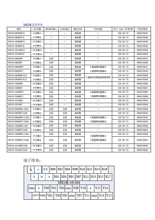
端子--PCB-----弹片式----------台湾进联--MX系列
- 格式:pdf
- 大小:1.13 MB
- 文档页数:1


PCB端子1. 简介PCB端子是电子设备中常用的连接部件,用于连接电路板和外部电路或设备。
它们通过插针或插座的形式提供电信号或电源传输。
PCB端子广泛应用于各种电子设备中,包括电脑、手机、家电等。
2. PCB端子的类型PCB端子的种类繁多,常见的类型有:2.1 螺钉端子螺钉端子是一种常用且可靠的连接方式,它通过螺丝将导线固定在端子上。
当需要更换线缆时,只需要拧松螺丝即可。
这种端子适用于大功率和高电流的连接。
2.2 弹簧式端子弹簧式端子使用弹簧夹紧导线,简化了连接过程。
它们通常用于低功率的连接,如传感器和模块之间的连接。
弹簧式端子的优点包括插拔次数多、连接稳定可靠、可防止接触不良。
2.3 压接端子压接端子是通过压接工具将导线压接在接触片上,实现电气连接。
这种端子通常用于较小功率和较低电流的连接,如电子元器件连接。
2.4 插座式端子插座式端子通常用于连接电子设备和外部电路,提供方便的插拔功能。
常见的插座式端子有D型插座、USB插座等。
它们广泛应用于计算机、手机和家用电器等领域。
2.5 可编程器连接端子可编程器连接端子是用于连接可编程器与目标板的接口,它们用于编程和测试电路板。
这些端子常用于生产线上的测试和编程步骤。
3. PCB端子的选型考虑因素在选择合适的PCB端子时,需要考虑以下因素:3.1 电流和功率需求根据电流和功率需求,选择适当的端子类型和规格。
对于大功率和高电流的连接,螺钉端子是一个理想的选择。
对于低功率连接,弹簧式、压接式或插座式端子可以满足需求。
3.2 空间限制PCB板上的空间有限,因此需考虑端子的尺寸和布局。
对于紧凑的布局,可能需要选择小型的端子类型或表面贴装端子。
3.3 环境要求考虑端子使用的环境条件,如温度、湿度、振动等因素。
对于恶劣环境下的应用,需选择耐腐蚀、耐高温或防水的端子。
3.4 插拔次数如果需要频繁插拔连接,弹簧式或插座式端子是更好的选择,因为它们具有较高的插拔次数和较低的接触阻抗。
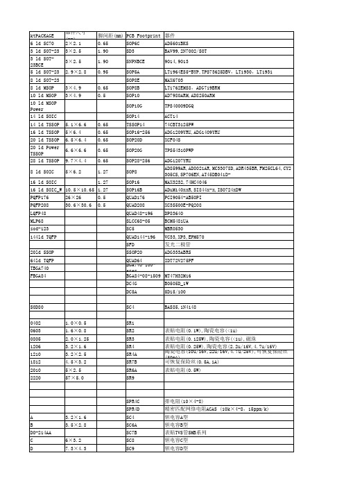
6098×100钢盖680120W推挽照4K4,810-80K 38×655.595×110×1166P3P,FU7,EL34,,KT88并管不锈钢盖950850120W推挽/8-10K可变4,810-80K 38×655.598×110×116805,845,211,813不锈钢盖950850150W推挽/8-10K 可变4,810-80K 38×756.598×120×116805,845,211,813不锈钢盖1080980DT-6 单端推动照/图600Ω 1.8K×210-50K22×321.367×60×802A3,300B,6N5P阴极接法,推805,845,211,813,6N5P,6C33C推挽或单端铝方罩500450DT-17单端推动照/图3.5K 1.75K×210-50K22×321.367×60×806V6,6P3P,6P14,EL34,2A3,300B单端,推805,845,211,813推挽或单端铝方罩400350DT-35 单端推动照/图3.5K 3.5K×210-50K22×321.367×60×806V6,6P3P,6P14,EL34,2A3,300B单端推845,211,813,6N5P,6C33C推挽或单端铝方罩550500RB-7推挽推动上无27厂照8K[P1-P2,电感15H/内阻178Ω]3.5K[1-4电感6.5H/内阻59Ω]10-80K/ 1.6ф85×956V6,6P14,2A3推挽推动/EL34,KT88,FU7,845,211,813,铁壳密封400RB-9单端推动娄东电子元件厂照 3.5K 2.1K40-60K16×250.4559×48×52飞跃R50/6P6P,6P14单端推动/FU7 X2夹包式每只90RB-28A单端/推动娄东电子元件厂照 3.5K 1.75K X240-60K19×310.9167×60×58飞跃R150/6P6P单端推动/FU7 X4夹包式每只10012.5W线间牛照0-0.5K-1K-2K-3K8,1640-12K 20×240.5565×50×54天津70-80年代生产的库存新品可用于收信机外接监听夹包式4615W线间牛照0-0.415K-0.83K-1.66K-2.5K8,1640-12K 20×240.5566×51×54天津70-80年代生产的库存新品可用于收信机外接监听夹包式487512机单端输出牛照出线图5.5K3.2Ω/600Ω/3000Ω20-20K 1.1266×80×86上无3厂7512机铁壳密封输出.可用做胆前级,无源前级,推动,唱头升.6P1,6V6,6P6P,6P14,EL84铁壳密封500拆美国军机牛661561照1照2照3自定出线头1-2-3/估计阻抗30K,出线头2是中心头,实测电感31H/内阻/2200欧。
CABLE GLAND FOR USE WITH UNARMOURED AND BRAID ARMOURED CABLESINCORPORATING EU DECLARATION OF CONFORMITY TO DIRECTIVE 2014/34/EUTECHNICAL DATACABLE GLANDTYPES A2e100RA2e100INSTALLATION INSTRUCTIONS FOR A2e100, RA2e100 CABLE GLANDGlasshouse Street • St. Peters • Newcastle upon Tyne • NE6 1BSTel: +44 191 265 7411 • Fax: +44 1670 715 646E-Mail:********************************.uk•Web:Notified Body: Sira Certification Service, Unit 6, Hawarden Industrial Park, Hawarden, CH5 3US, UK0518CABLE GLAND TYPE : A2e100, RA2e100INGRESS PROTECTION: IP66, IP67, IP68PROCESS CONTROL SYSTEM : BS EN ISO 9001ISO/IEC 80079-34:2011C M PD o c u m e n t N o . F I 493 I s s u e 4Logo’s shown for illustration purposes only. Please check certification for detailsEN 60079-0:2012/A11:2013, EN 60079-7:2015, EN 60079-15:2010, EN 60079-31:2014, BS 6121:1989, EN 62444:2013David Willcock - Certification Engineer (Authorised Person)CMP Products Limited, Cramlington, UK, NE23 1WHSCAN FOR INSTALLATION VIDEOSEXPLOSIVE ATMOSPHERES CLASSIFICATIONATEX CERTIFICATION No : SIRA16ATEX3165, SIRA16ATEX4020ATEX CERTIFICATION CODE : ^ II 2G Ex eb IIC Gb, II 1D Ex ta IIIC Da IP66, IP67, IP68^ II 3G Ex nRc IIC Gc IP66 ^ I M2 Ex eb I Mb IP66, IP67, IP68IECEx CERTIFICATION No : IECEx SIR 16.0053IECEx CERTIFICATION CODE : Ex eb IIC Gb, Ex ta IIIC Da, Ex nRc IIC Gc, Ex eb I Mb IP66, IP67, IP68A2e100 - no face seal RA2e100 - with face seal1. Read all instructions before beginning installation. Installation shall only be performed by competent, suitably trained personnel (in accordance with EN/IEC 60079-14) using the correct tools; spanners should be used for tightening.2.Inspection and maintenance shall only be performed by competent, suitably trained personnel (in accordance with EN/IEC 60079-14 (Initial Inspection) and EN/IEC 60079-17).3.Ingress Protection Statement; The interface between a cable entry device and its associated enclosure / cable entry cannot be defined. It is the user’s responsibility to ensure that a minimum protection level (IP54 for explosive gas atmospheres and IP6X for explosive dust atmospheres) is maintained at the interface. Entry component threads may need additional sealing to maintain the ingress protection rating and/orrestricted breathing performance as applicable to the equipment to which it will be attached, such as by either a sealing washer, thread sealant or integrated ‘O’ ring face seal (RA2e100). Reference should also be made to the information from EN 60079-14:2014, Clause 10, Table 10, (Note: When fitted to a threaded entry, all tapered threads will automatically provide an ingress protection rating of IP6X).4. The standard product temperature range is -60°C to +130°C. The equipment should not be used outside of this range.5. Cable glands do not have any serviceable parts and are therefore not intended to be repaired.6. Cable glands are manufactured from Brass, Nickel Plated Brass, Stainless Steel, Mild Steel or Aluminium, with Silicone seals. The end user shall consider the performance of these materials with regard to attack by aggressive substances that may be present in the hazardous area. Consideration should be given to potential degradation due to galvanic corrosion at the interface of dis-similar metallic materials.7.It is the end user’s responsibility to ensure the equipment materials are suitable for their final installation location. If in doubt consult CMP Products Limited.IMPORTANT NOTES FOR INSTALLERSSPECIAL CONDITIONS FOR SAFE USE None INSTALLATION INSTRUCTIONS FOR CMP CABLE GLAND A2e100, RA2e100CABLE GLAND COMPONENTS - It is not necessary to dismantle the cable gland any further than illustrated below 1. Entry Item 2. Seal 3. Seal NutPLEASE READ ALL INSTRUCTIONS CAREFULLY BEFORE BEGINNING THE INSTALLATION1. It is not necessary to dismantle the gland any further than illustrated below.where required to reveal the insulated conductors.4. Slacken the seal nut (3) to relax the seal (2).5. Only using finger pressure, tighten the seal nut until light resistance to tightening is met.Then either use the seal tightening guide tape or table on the rear of the page to determine how much further to tighten the seal using a spanner (using the outer seal tightening guide is recommended).Wrap the seal tightening guide tape around the cable to show the amount of spanner turns needed (as shown here). Make sure the correct side of the seal tightening guide tape is used depending on the cable gland size.。
1、?KF2510-4P接线端子2.54mm间距型号:KF2510间距:2.54mm线数:2、3、4、5、6、7、8、9、10、11、12----20P 2、CH3.96-2P接插件3.96MM间距接线端子型号:CH3.96间距:3.96mm线数:2、3、4、5、6、7、8、9、10、11、12----16 3、?VH3.96-2P接插件3.96MM间距型号:VH3.96间距:3.96mm线数:2、3、4、5、6、7、8、9、10、11、12----16 4、XH2.54-2P接线端子2.54mm间距规格参数:?5、PH2.0-4P接线端子2.0mm间距?规格参数:6、?7、KF141R-2.54弹簧式型号:KF141R-2.54产品:免螺丝式弹簧式接线端子连接器8、KF141V-2.54弹簧式PCB接线端子型号:KF141V-2.54产品:免螺丝式弹簧式接线端子连接器接线口在上面9、KF142R-5.08弹簧式PCB接线端子10、KF142V-5.08弹簧式型号:KF142V-5.08产品:免螺丝式弹簧式接线端子连接器11、?KF-301 KF301-2P?型号:KF301-5.0-2P规格:5.00mm间距电压电流:300V 12A线径:22-14AWG 2.5mm212、?KF-7.62 KF7620-2P 7.62MM间距2P塑件:PA66 UL94V-0端子:黄铜,0.8厚镀锡螺丝:钢,M4镀镍性能额定电压/电流:300V/20A使用温度:-40oC~+105oC耐电压:AC2000V/Min绝缘电阻:500M?/DC500V使用线径:22~12AWG最大锁紧扭力:10kg/cmKF128-2P 5.00MM-2P ?螺丝:M2.5,钢,镀锌焊针:黄铜,镀锡塑件:PA66, UL94V-0电气性能额定电压:300V额定电流:16A接触电阻:20mΩ绝缘电阻:5000MΩ/1000V耐电压:AC1500V/1Min使用线径:24-12AWG 2.5mm2机械性能温度范围:-40oC~+105oC瞬时温度:+250oC? 5秒扭距:0.4Nm (剥线长度:6-7mm13、螺钉式端子接线端子KF120-2P 间距2.54MM? 接线端子KF120-2P间距2.54MM 一体端子14、SM2.54-2P 间距2.54mm线束空中对接连接线型号:SM-2P线束间距:2.5mm15、?EL 6P 条形连接器? )汽车连接器16、接插件5556-2P 对插接插件,连接器L6.2-4P对接连接器L6.2技术参数:间距:6.2适用线规:AWG#24~#14额定电压:300V DC/AC(有效值)额定电流:10.0A耐压值:1500V AC (有效值)工作温度:-25℃~+85℃绝缘电阻:≥1000MΩ接触电阻:≤0.02Ω材料:绝缘座:尼龙66 UL94V-0端子:磷青铜5566 5557 4P 接插件接线接头端子(可能有两种,一种接PCB ,一种为空中对插)\连接器5566 2-24芯现货供应? 间距4.2mm1、接线端子接插件CF-3P 条形连接器间距6.35MM仅供个人用于学习、研究;不得用于商业用途。
s FEATURES•Many applicationsVarious connectors are available for connection by means of soldering, wire wrapping, crimping, PC board mounting, and insulation displacement connection (IDC). The user can choose a plug and jack combination that best meet each application.•Small size for high-density mountingThe connectors are small with a contact and terminal pitch of 2.54 mm (0.100 in.) between pins and between rows and are thus well suited for high-density mounting.•Sturdy shell guideSturdy shell guides are used to prevent mismating and to protect the pins.•Excellent cost performanceStreamlined design and automated manufacturing,including use of partial solder plating, provide excellent cost performance.s SPECIFICATIONSs MATERIALSRECTANGULAR CONNECTORSFCN-360 SERIESItemOperating temperature range Current Rating Voltage Rating Contact resistance Insulation resistance Dielectric withstanding voltage Insertion force Withdrawal forceApplicable wireApplicable PC boardSpecification–55°C to +85°C DC 3A (IDC type: 1 A)AC 250V15 m Ω max. (DC 6 V, 0.3 A)1000 M Ω min. (DC 500 V)AC 500 V for 1 minute2.5 kg max. (8 contacts), 20 kg max. (64 contacts)0.3 kg min. (8 contacts), 2.3 kg min. (64 contacts)φ0.60 mm (0.024 in.) max, AWG #23 or less φ0.32 mm (0.013 in.) to φ0.26 mm (0.010 in.), AWG #28 to #30Standard contacts φ0.51 mm (0.020 in.) to φ0.32 mm (0.013in.), AWG #24 to #28, insulator φ1.2 mm (0.047 in.) max.Contacts for thick wires φ0.64 mm (0.025 in.) to φ0.32 mm (0.013 in.), AWG #22 to #28, insulator φ1.7 (0.067 in.) max.Flat cable 1.27 mm (0.050 in.) pitch, AWG #28 (stranded wire),AWG #30 (solid wire)1.6 mm (0.063 in.) standard thickSoldering Wire-wrappingCrimpingIDCItem Insulator Conductor PlatingMaterialPolyester (363J: PC94V-2)Copper alloyGold plating, silver platingNot for New DesignACCESSORIESs MOUNTING SYLENote:When the jack or plug without a cover (shaded part) is used, have M2.6 × 8 mm machine screws ready inorder to tighten the connector.s SHAPES AND DIMENSIONS OF METAL FITTINGS1.Straight Mounting Metal Fittings2.Right-angle Mounting Metal Fittings3.Straight Mounting Round Metal Fittings© 2001 Fujitsu Components America, Inc. All company and product names are trademarks or registered trademarks of their respective owners. Rev. 09/2001JapanFujitsu Component Limited Gotanda-Chuo Building3-5, Higashigotanda 2-chome, Shinagawa-ku Tokyo 141, Japan Tel: (81-3) 5449-7010Fax: (81-3) 5449-2626Email:************** Web: North and South AmericaFujitsu Components America, Inc.250 E. Caribbean DriveSunnyvale, CA 94089 U.S.A.Tel: (1-408) 745-4900Fax: (1-408) 745-4970Email:*******************.com Web: EuropeFujitsu Components Europe B.V.Diamantlaan 252132 WV Hoofddorp NetherlandsTel: (31-23) 5560910Fax: (31-23) 5560950Email:***************************.com Web: Asia PacificFujitsu Components Asia Ltd.102E Pasir Panjang Road#04-01 Citilink Warehouse Complex Singapore 118529Tel: (65) 375-8560Fax: (65) 273-3021Email:*****************.com Fujitsu Components International Headquarter Offices。