Pubwin2009安装培训
- 格式:ppt
- 大小:2.16 MB
- 文档页数:135

一、背景为了确保我司产品在客户现场安装过程中能够顺利进行,提高安装效率和质量,降低安装风险,特制定本安装指导方案及培训计划。
二、目标1. 提高安装人员对产品的熟悉程度和操作技能;2. 优化安装流程,缩短安装周期;3. 降低安装过程中的风险和故障率;4. 提升客户满意度。
三、安装指导方案1. 安装前的准备工作(1)对安装人员进行产品知识培训,使其熟悉产品性能、结构、功能及操作方法;(2)核实现场环境是否符合安装要求,确保现场安全;(3)准备安装所需的工具、材料和设备;(4)制定详细的安装方案,明确安装步骤和注意事项。
2. 安装过程(1)按照安装方案进行现场施工,确保操作规范;(2)对安装过程中出现的问题及时进行沟通和解决;(3)做好安装过程中的记录,包括安装时间、材料消耗、问题处理等;(4)对安装完成的设备进行检查,确保其正常运行。
3. 安装后的验收(1)对安装完成的设备进行功能测试,确保其性能符合要求;(2)对安装现场进行清理,确保现场整洁;(3)收集客户反馈意见,对安装过程中存在的问题进行改进。
四、培训计划1. 培训对象(1)新入职的安装人员;(2)有一定安装经验但需要提升技能的安装人员;(3)部门负责人及管理人员。
2. 培训内容(1)产品知识培训:包括产品性能、结构、功能及操作方法;(2)安装工艺培训:包括安装步骤、注意事项、常见问题及解决方法;(3)安全知识培训:包括现场安全、操作安全、应急处置等;(4)沟通技巧培训:包括与客户、同事的沟通方式及技巧。
3. 培训方式(1)现场教学:由经验丰富的安装工程师进行现场操作演示;(2)理论培训:通过讲解、讨论、案例分析等方式进行;(3)实践操作:安排安装人员进行实际操作,由培训师进行指导;(4)考核评估:对培训效果进行考核,确保培训质量。
4. 培训时间(1)新入职安装人员:培训周期为1个月;(2)有一定安装经验但需要提升技能的安装人员:培训周期为2周;(3)部门负责人及管理人员:根据实际需求进行不定期的培训。

Pubwin2009升级教程准备工作:网吧升级之前,需提前一至两天联系华润公司,以便开通新版本接口注册号联系电话:871970001.由于2009的服务端不兼容2007的客户端。
所以必须先升客户端再升级服务端和控制台。
a)07版本客户端版本在0812之前的,需卸载原客户端重新安装新版本客户端。
不管是否有讯闪还原,建议采用去还原的升级,这样可以保证客户端升级的成功率。
(注意这个地方如果驱动是老的要在升级完后重启一次)b)0812以后的客户端可以通过讯闪穿透还原,但需要注意讯闪服务器上的一个文件HFileTran.dll的版本号,需要使用1.0.0.10(此文件为讯闪的文件)c)如果使用讯闪穿透升级,需要重启客户端验证升级是否成功,可能存在穿透失败的问题,此问题通过检查可以找出,可以采用重新升级或者重做客户端两种方式,建议采用重做客户端的方式解决,保证成功率d)部分使用09以上客户机版本的,可以使用客户机升级包。
需将客户机升级包放置于Hintsoft\PubwinServer\appServ\server\webapps\NetCafe\update (其中update目录需自己新建)★.注:客户机需去还原以后再升级,不然将出现蓝屏。
2.确认价格方案-匹配条件集合中的“用户类型(会员等级)”和“客户机类型”是真实存在的,如果会员等级列表和客户机类型列表中没有匹配条件集合中所添加的会员等级和客户机类型,请手动添加。
否则会导致数据转换失败。
3.备份数据,并备份原来的老版本服务。
建议备份整个PubwinServer目录★注:由于Pubwin2009数据库的结构改变,升级完成后只能看到会员信息,将不能看到升级之前Pubwin2007的营业数据(包括消费记录,会员充值记录等)。
建议解决办法是另装一台2007的服务,把备份的数据拷贝回去,在后台把客户机列表删除,以备查看升级之前的营业数据(包括消费记录,会员充值记录等)。

安装调试及培训实施方案一、引言。
在现代信息化的环境下,软件系统的安装、调试及培训实施是一个重要的环节。
本文档将详细介绍安装调试及培训实施方案,以帮助用户更好地了解和掌握相关知识。
二、安装方案。
1. 硬件准备。
在进行软件安装前,需要对硬件进行准备。
首先要确保计算机硬件配置达到软件运行的最低要求,包括CPU、内存、硬盘等方面。
另外,还需要检查网络设备、打印设备等外部设备的连接情况。
2. 软件安装。
在进行软件安装时,需要先进行系统环境的检测,确保系统环境的稳定性。
然后按照软件安装向导的步骤逐步进行安装,注意选择安装路径和相关组件。
安装完成后,进行软件的初始化配置,设置相关参数和权限。
三、调试方案。
1. 系统调试。
在软件安装完成后,需要进行系统调试,确保软件的正常运行。
首先进行系统功能测试,测试软件的各项功能是否正常。
然后进行性能测试,测试软件的性能是否达到要求。
最后进行安全测试,测试软件的安全性是否符合标准。
2. 数据调试。
在系统调试完成后,需要进行数据调试,确保数据的完整性和准确性。
首先进行数据导入测试,测试数据的导入是否成功。
然后进行数据处理测试,测试数据的处理是否正确。
最后进行数据备份测试,测试数据的备份是否可靠。
四、培训实施方案。
1. 培训准备。
在进行培训前,需要对培训进行准备。
首先确定培训的内容和形式,包括培训的主题、时间和地点。
然后准备培训材料,包括培训手册、演示文稿等。
另外,还需要确定培训的讲师和参与人员。
2. 培训实施。
在进行培训时,需要按照培训计划进行实施。
首先进行培训的开场白,介绍培训的主题和目的。
然后进行培训内容的讲解和演示,确保参与人员能够理解和掌握相关知识。
最后进行培训的总结和反馈,收集参与人员的意见和建议。
五、总结。
安装调试及培训实施是软件系统运行的重要环节,需要认真对待。
通过本文档的介绍,相信用户能够更好地了解和掌握相关知识,为软件系统的运行提供有力支持。
希望本文档能够对用户有所帮助,谢谢阅读!。

软件安装培训计划一、培训目的软件安装培训旨在为员工提供必要的技能和知识,使他们能够独立地安装和配置软件。
通过培训,员工将能够了解软件的基本功能和操作方法,提高工作效率并减少因软件安装不当而导致的问题。
二、培训对象本次培训主要对象为公司内部需要经常进行软件安装的技术人员、IT支持人员以及需要使用特定软件的员工。
三、培训内容1. 软件安装基础知识- 软件安装原理- 软件安装相关术语和概念- 安装文件格式与适用环境2. 安装前准备- 硬件和软件环境检查- 确定权限及用户账号- 准备安装文件和相关资料3. 安装过程- 安装步骤介绍- 安装选项及注意事项- 安装过程中的常见问题解决4. 配置与更新- 基本配置设置- 软件更新与升级- 配置文件备份与恢复5. 安装测试- 安装后的系统测试- 安装完成后的验证步骤- 操作系统兼容性测试6. 安全与问题解决- 安全设置与防护措施- 安装过程中可能出现的常见问题与解决方法 - 病毒防护与恢复7. 功能与操作- 软件基本功能及操作介绍- 快捷键和常用操作方法- 高级功能使用技巧8. 使用与维护- 软件的日常使用注意事项- 用户权限管理- 软件维护与升级四、培训方式1. 理论培训- 由专业讲师进行授课- 通过PPT、视频等方式进行讲解- 可以进行在线培训或面对面培训2. 实践操作- 提供实际软件安装及配置操作演练- 培训人员可自行安装及测试指定软件3. 答疑交流- 提供问题咨询与答疑环节- 对安装过程中出现的问题进行解答五、培训时间与地点1. 培训时间:根据实际情况安排,一般为1-2天。
2. 培训地点:公司内部会议室或线上视频会议。
六、培训考核1. 考核形式:授课考核、实际操作考核、笔试等形式结合。
2. 考核内容:理论知识、实际操作能力、问题解决能力。
七、培训后续跟踪1. 培训结束后,将根据培训效果留出一定时间进行实际操作,并提供技术支持。
2. 对员工在实际操作中出现的问题进行跟踪和解决,确保培训效果得到落实。

安装培训计划模板1. 培训目标本次培训的主要目标是让参与培训的员工熟悉并掌握公司的安装流程和规定,提高他们的安装技能,并且了解公司的安装政策和方针。
通过培训,员工将具备独立完成公司规定的安装任务的能力。
2. 培训内容(1)公司的安装流程和规定- 安装前的准备工作- 安装过程中的注意事项- 安装后的验收和报告(2)安装工具和使用方法- 常用的安装工具及其使用方法- 安装中常见的问题及解决方法(3)安装技能培训- 安装技能的基础知识- 安装技能的实际操作训练(4)安装政策和方针- 公司的安装政策和方针- 对于安装工作的奖惩政策3. 培训时间和地点本次培训将在公司内部进行,培训时间为连续5天,每天8小时,具体时间安排将在通知中另行通知。
4. 培训方式本次培训将采用理论教学和实际操作相结合的方式进行,通过专业的培训讲师为员工进行讲解和演示,并进行实际操作指导。
5. 培训对象本次培训对象为公司新员工以及进行安装工作的员工,总共约有50人参加培训。
6. 培训安排第一天:公司安装流程和规定的讲解和理论学习第二天:安装工具和使用方法的讲解和实际操作演示第三天:安装技能的基础知识和实际操作训练第四天:安装政策和方针的讲解和案例分析第五天:安装技能的实际操作训练和总结7. 培训评估在培训结束后,将对参与培训的员工进行培训评估,以检测培训效果。
同时也将实时收集员工的反馈意见,帮助不断改进培训内容和方法。
8. 培训考核培训结束后公司将进行相关考核,对参与培训的员工进行安装技能的考核和评估,以确定是否熟练掌握了安装工作的技能。
以上就是本次安装培训计划的模板,希望对您有所帮助。
祝您的培训工作顺利!。

一、培训背景随着科技的不断进步,各类设备的安装和维护已成为企业运营中不可或缺的一环。
为了提高员工的专业技能,确保安装工作的质量和安全,特制定此安装方案培训计划。
二、培训目标1. 使员工掌握各类设备的安装流程和注意事项;2. 提高员工的安全意识,确保安装过程中的安全;3. 培养员工的团队协作能力,提高工作效率;4. 使员工熟悉售后服务流程,提升客户满意度。
三、培训对象公司全体安装人员、售后服务人员及相关部门人员。
四、培训内容1. 安装基础知识a. 安装工艺流程;b. 安装工具及设备的使用方法;c. 安装材料的选用与保管。
2. 安全知识a. 安全操作规程;b. 常见事故案例分析;c. 应急处理措施。
3. 设备安装a. 各类设备的安装流程;b. 设备安装过程中的注意事项;c. 特殊情况下的安装技巧。
4. 设备调试与验收a. 设备调试方法;b. 设备验收标准;c. 设备故障排查与处理。
5. 售后服务a. 售后服务流程;b. 客户投诉处理;c. 设备保养与维护。
五、培训方式1. 理论授课:邀请专业讲师进行授课,讲解安装相关知识;2. 实操演练:组织学员进行现场实操,巩固所学知识;3. 案例分析:通过案例分析,提高学员的安全意识和解决问题的能力;4. 互动交流:组织学员进行分组讨论,分享经验,共同进步。
六、培训时间1. 安装基础知识:2天;2. 安全知识:1天;3. 设备安装、调试与验收:3天;4. 售后服务:2天。
七、培训考核1. 理论考核:考试形式,合格分数线为80分;2. 实操考核:现场操作,考核合格后可获得实操证书;3. 综合考核:结合理论、实操及案例分析,综合评定学员的培训成果。
八、培训效果评估1. 定期对培训效果进行评估,了解学员掌握程度;2. 根据评估结果,调整培训内容和方式;3. 对优秀学员进行表彰和奖励,激发学员的学习积极性。
通过本培训计划,旨在提高公司员工的安装技能和安全意识,为公司的持续发展提供有力保障。


给客户安装软件培训的方式方法及流程一千字下载提示:该文档是本店铺精心编制而成的,希望大家下载后,能够帮助大家解决实际问题。
文档下载后可定制修改,请根据实际需要进行调整和使用,谢谢!本店铺为大家提供各种类型的实用资料,如教育随笔、日记赏析、句子摘抄、古诗大全、经典美文、话题作文、工作总结、词语解析、文案摘录、其他资料等等,想了解不同资料格式和写法,敬请关注!Download tips: This document is carefully compiled by this editor. I hope that after you download it, it can help you solve practical problems. The document can be customized and modified after downloading, please adjust and use it according to actual needs, thank you! In addition, this shop provides you with various types of practical materials, such as educational essays, diary appreciation, sentence excerpts, ancient poems, classic articles, topic composition, work summary, word parsing, copy excerpts, other materials and so on, want to know different data formats and writing methods, please pay attention!给客户安装软件培训的方式、方法及流程引言在当今数字化时代,软件已经成为企业提高效率、管理业务的重要工具。
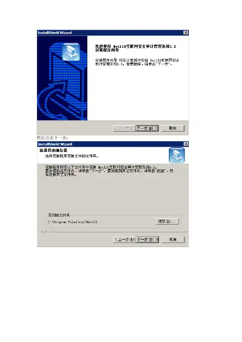
一、安装Net110互联网信息安全审计管理系统首先解压压缩包然后打开文件夹找到并点击出现先安装网络协议,然后双击安装Net110互联网信息安全审计管理系统Ver 5.2然后点击下一步;选择安装目录,放置在非系统盘里;然后确定;然后点击下一步;继续下一步;继续下一步;看一下文件存放目录是否为非系统盘,如果不是系统盘然后点击下一步;看一下网段设置是否正确;看一下设置的是否正确,正确的话点击下一步;开始安装了;选择不重启,点完成。
然后在开始——程序——Net110互联网安全审计管理系统5.2;打开Net110互联网安全审计管理系统5.2;选择旧注册模式(默认);点击下一步;在中心地址填上27.189.197.66;在中心端口填上8080;下边的单位编号和和注册序列号联系我们。
二、Pubwin2009服务器安装步骤(一)备份Pubwin2009服务器从新安装pubwin2009服务器(以下简称服务器)之前,要先检查自己网吧安装的服务器是什么版本路径如下X:\Program Files\Hintsoft\PubwinServer\version这个路径下有个文件version_description.xml 打开可以看到第五行的数字就是版本号,安装服务器一定要安装同版本的服务器,否则服务器不能正常启动。
从新安装服务器之前,要将之前的数据库进行备份。
X:\ProgramFiles\Hintsoft\PubwinServer\database 这个路径下的文件都要备份。
备份好数据库后在卸载服务器,然后将这个服务器文件夹pubwinserver改名(重命名)。
(二)检查系统相关配置检查IE增强组件是否删除,选择删除。
请检查系统是否安装有防火墙检查方法为:打开控制面版(开始-设置-控制面版或者开始-运行-control)-(切换到经典视图)- 网络连接–本地连接。
右键单击本地连接选择属性,打开本地连接的属性中的高级- 设置–选择关闭。
FME Training ManualWorkspaces GenericGeneric Workspaces (3)Why Make Generic Workspaces? (3)Example Scenarios (3)What can be made Generic (4)Generic Formats (5)The Generic Writer (5)Example 1 – The Generic Writer (6)Generic Source Layers (7)Undefined Feature Types (7)Feature Type Selection (8)Feature Types to Read (8)Example 2 – Feature Types to Read (10)Generic Destination Layers (11)Data Fanouts (11)Feature Type Fanout (12)Feature Type Fanout Basics (12)Example 3 – Feature Type Fanout (13)Dataset Fanout (15)Dataset Fanout Basics (15)Example 4 – Dataset Fanout (16)Batching Processing Fanouts (18)Methodology (18)Drawbacks (19)Generic Attributes (20)Dynamic Schemas (20)Example Scenarios (21)Example 5 – Generic Writer and Dynamic Schema (22)Generic Workspaces Summary (24)Overview Table (24)Use Cases (25)Session Review (26)What You Should Have Learned from this Session (26)Page 8-2 Generic WorkspacesFME Training ManualGeneric WorkspacesPage 8-3Generic WorkspacesGeneric workspaces are a way of providing maximum translation flexibility with minimum effort.Why Make Generic Workspaces?While FME translations are generally very easy to implement, it still isn’t very good practice to duplicate workspaces – maybe multiple times – for very minor changes.Likewise, it really isn’t best practice to add multiple writers to one workspace, unless absolutely necessary.Such behaviour – as well as adding unnecessary work for a workspace author – places additional burdens on the end-user as they are forced to pick and choose between translations with very few differences.A Generic workspace is one that can be re-used for a number of purposes, without having to be edited each time.Example ScenariosSome example scenarios where a generic translation would be of benefit are:- When the source data transformations remain constant, but the output format varies .- When the output format remains constant, but the destination coordinate-systemvaries .- When the formats remain constant, but the data transformations vary .- When the format and transformations remain constant, but the number and structure ofoutput datasets varies .- Any combination of the above… plus many more!Police Chief Webb-Mapp says…“Many of these scenarios are those you specifically find on an FME Server installation, for which reason the topics in this session are very important for users authoring workspaces for that environment.”FME Training ManualPage 8-4Generic WorkspacesWhat can be made GenericThere are a number of components that you could genericize in an FME workspace:• FormatA workspace that would read from any format and write to any format, without the need to add multiple readers or writersWriting is supported by the Generic Writer, created in FME2008• Schema: LayersA workspace that would read any set of layers from a source dataset, and would write any set of layersThis is supported by the Merge Filter and Data Fanouts• Schema: AttributesA workspace that would read any set of attributes and write them out too, regardless of the defined schemaThis is supported by Dynamic Schemas, introduced in FME2009Ultimately, the Utopian vision for an FME user is a workspace which has only a single Reader and a single Writer, but which is capable of being used to read any data in any format and with any schema, and to write it out to any other format.- This vision is now in sight, but this wasn’t a single evolutionary leap; as you can seegeneric FME functionality was implemented in a number of stages.The Generic ReaderThe Generic Reader is at the moment only a future concept. It may be implemented in FME2010.It would be the source equivalent of the Generic Writer; a Reader that could accept any format dataset.FME Training ManualGeneric WorkspacesPage 8-5Generic FormatsThe Generic Writer is the primary tool by which a workspace can be made format independent on the destination side.The Generic WriterThe generic writer is an object – or format – that represents a destination without a specific format.When a workspace with such an object is run, the format of data written is determined by a parameter that can be set in the Navigator pane.Right : Here a workspace is being set up to convert park data using a Generic WriterOnce created, this workspace means the user is permitted to choose which format to write to.Left : The Navigator pane content for theworkspace shows not just a destination location parameter, but also one for destination format.NB : the destination is always a directory, even when the selected format is file-based.Right : Because the destination format parameter can be published, the user can be prompted to select the output format at run-timeFME Training ManualPage 8-6Generic WorkspacesExample 1 – The Generic WriterThis example demonstrates use of the Generic Writer.Objective: We wish to create a workspace which will translate Interopolis transit data and upload it to FME Server. This will let residents of the city download the data over the Internet. However, we wish to give users the choice of which format they want the data in.Detailed Steps1) Set up Translation.Start Workbench and create a translation from Autodesk SDF to Generic (Any Format).Source Format Autodesk MapGuide Enterprise SDF Source Dataset C:\FMEData\Data\Transit\Transit.sdf Destination Format Generic (Any Format)For the destination settings you should set:Dynamic Schema NoOutput FormatESRI Shape2) Publish ParameterOne of the objectives is to give the user the choice of which format to write to.Locate the Output Format parameter in the Navigator pane and publish it (left )3) Re-Run Workspace.Re-run the workspace using the Prompt and Run option. You will be given the choice of which format to write to.This proves we have a workspace capable of converting the Interopolis transit dataset into any output format!Professor Spatial F.M.E., E.T.L. says…“Interestingly, even though the initial Generic Writer output format was Shape, Workbench did not include a set of GeometryFilter transformers.That’s because the task of sorting out geometries (in geometry restricted formats) is left to the Generic Writer itself. It has to be otherwise the workspace would not be very generic!”FME Training ManualGeneric WorkspacesPage 8-7Generic Source Layers“Feature Types to Read” is a Reader parameter for advanced control of workspace feature types. It helps to make complex workspaces more generic.To make a workspace dynamically read a series of user defined – but previously unknown – layers, we need to be able to handle undefined feature types, and provide a means to control existing feature types.Undefined Feature TypesOne method of workspace design is to add all source data and feature types into a single workspace.The drawback there is that the method is not dynamic: it cannot handle Feature Types that have not been defined beforehand.Going back to session 5 (Datasets and Feature Types) we learned that one way to handle this is through Merge Feature Type .Merge Feature TypeRemember that the Merge Feature Type Filter is a definition of what Feature Types are to be permitted to pass. Therefore it is a way to make a generic workspace: with a merge filter set we can read any source layers whether or not they are predefined in the workspace.Left : The example from session 5.The user has ticked the ‘Merge feature type’box and entered * as a wildcard filter.FME Training ManualPage 8-8Generic WorkspacesFeature Type SelectionEven if we do create a workspace where all source data and feature types are already defined, often the end user will not want to read all of these: they will wish to be more selective.For example here (right ) the workspace contains a number of Feature Types (BusRoutes, BusStops and metrorail) but – as a workspaceauthor – we wish to limit reading to a subset of these, and give the end user the ability to define this selection.Disabling Feature TypesThe most obvious method of control is to disable the superfluous feature types (like BusRoutes) or even delete them (like metrorail) before running the workspace (left ).However, this obviously entails the end-user making edits to theworkspace, and not being able to selectively turn layers on and off at run-time.Feature Types to ReadThe “Feature Types to Read” parameter solves the problem of Feature Type selection dynamically (i.e. without having to edit the workspace).It is a Reader parameter which can be used to select which of the defined feature types will be allowed to pass.You could think of it as a filtering mechanism for unwanted data; a more sophisticated version of the merge filter.Right : Three different feature types are listed under this writer. Notice the “Feature Types to Read” parameter just above this list.Its current value is <not set> which means that the user has not used it and all features will be read from the source.Like all parameters, this one can be edited with a double-click.Left : The user is editing the parameter and sets it up to read only Rail, Rivers and Roads.Below : The Feature Types to Read parameter now looks like this in the Navigator pane:FME Training ManualGeneric WorkspacesPage 8-9Right : After running the workspace, the feature counts show that only features from the selected feature types have been permitted to pass into the workspace. .Again, because the parameter is publishable, this allows a generic workspace to be set up from which a user chooses which feature types to read at run time.Left : By publishing the Feature Types To Read parameter the user can be prompted for it at run time …Right : …which means it can also be set on the command line.LimitationsIt’s an advanced point, but Feature Types to Read only lists what Feature Types are defined in the workspace. It won’t re-read the source datasets to find extra ones that aren’t defined, and it can’t be forced by setting a merge filter.In other words, if I have a database reader, my choice of tables is limited to what is defined in the workspace. FME won’t check the database and give me a list of all tables, as some users expect.This is something likely to be addressed in future versions of FME, as part of the Generic Reader.Another probable future enhancement is the ability to create “groups” of feature types, and have the user pick groups rather than individual feature types.For example – in the above workspace – Rail and Roads could be set up as a group called Transportation , and Buildings and Schools set up as a group called Structures .FME Training ManualPage 8-10Generic WorkspacesExample 2 – Feature Types to ReadThis example demonstrates use of the Feature Types to Read parameter.Objective: We wish to expand on the workspace from example 1, by allowing users the choice of which source Feature Types they wish to translate.Detailed Steps1) Set up Translation.Start Workbench (if necessary) and open the workspace from example 12) Set up Feature Types to ReadLocate the Feature Types to Read parameter in the Navigator pane. Publish the parameter.3) Run Translation.Save the workspace (we’ll use it again later) and run the translation using File > Prompt and Run. Restrict the workspace to reading BusRoutes and BusStops.Inspect the output (and the Workbench log window) to make sure the output is correct.FME Training Manual Generic Destination LayersFanouts are one of the most powerful pieces of functionalitywithin FME, capable of producing impressive results withvery little effort.On the destination side of a workspace, you could think of Feature Type manipulation as more “Dynamic” than “Generic”; the idea being to write impromptu Feature Types on the basis of some user-defined input.Data FanoutsA fanout is a way of splitting up data into multiple outputs without specifically adding these outputs to the destination schema first. It counts as “generic” because the splitting-up action happens “on-the-fly”, without any edits or updates needing to be made to the workspace.FME’s default behaviour is to merge multiple source datasets into a single output dataset. In general, multiple destination datasets are achieved by adding multiple writers (each with a single dataset) and directing source features into them.A fanout causes multiple outputs to be created automatically by diverting data to different feature types or datasets depending on the value of a user-specified attribute.Left: Here a sourcedataset of elevation data isbeing fanned-out intomultiple outputs accordingto each feature’s elevationvalue.Sound familiar? The technique is very similar to a “merge filter” applied to source data. In fact, some FME users refer to the merge filter as a “Fan-In”!A major benefit of a fanout is the high degree of flexibility – and freedom from fixed-layer schemas – in return for minimal setup effort.There are two types of fanout: Feature Type Fanout and Dataset Fanout.FME Training ManualFeature Type FanoutA Feature Type Fanout diverts data to different layers withina single dataset.Feature Type Fanout BasicsRather than create a number of outputdatasets, a feature type fanout diverts datato different feature types (layers) within asingle destination dataset.Right: This elevation data is being divided upinto segments based on an elevation attribute.Each segment is written to a different layer(feature type) within a single DXF file.A feature type fanout is defined using adestination feature type’s propertiesdialog.Left: A feature type fanout set up torepresent the diagram above.Data is written to an AutoCAD dxf fileand fanned-out by an attribute called‘elevation’.A new feature type (layer in DXF) iscreated for each value of the ‘elevation’attribute, and features with that valuewritten to that feature type.FME Training Manual Example 3 – Feature Type FanoutThis simple exercise applies a feature type fanout to a City of Interopolis dataset.ObjectiveThe engineering department has a set of AutoCAD files holding information on water distribution pipelines. Your task is to create a GML dataset where each diameter of pipeline is stored on a separate level.Detailed Steps1) Set Up Translation.Start Workbench and create a translation from AutoCAD to GML.Source Format Autodesk AutoCAD DWG/DXFSource Dataset C:\FMEData\Data\Water\distribution_L25.dwgDestination Format GML (Geography Markup Language)Before accepting the new workspace, click thesettings button and ensure the AutoCAD sourcefeature types will be grouped by the AutoCADattribute schema.The only source feature type we require in theworkspace is water_distribution_lines2) Set Up FanoutOpen the feature type properties dialog forthe water_distribution_lines feature type.Place a checkmark in the box to activate aFeature Type Fanout. Select DIAMETER asthe fanout attribute.FME Training Manual3) Set a Coordinate SystemFME is unable to create GML data without a known coordinate system. Because it cannot read one from the source AutoCAD data it will have to be user-defined.Set the destination coordinate system to TX83-CF.Use either the coordinate system settings in thenavigation pane, or a CoordinateSystemSettertransformer.4) Run the TranslationSet a destination GML file to write to and run the translation. A single GML file will be created.Open the output GML file in theFME Universal Viewer. Noticehow a different feature type(layer) has been created foreach different diameter pipeline(left)5) Create a Second FanoutA second task now awaits – the creation of a second set of layers.Duplicate the existing destination feature type using right-click > duplicate.Rename the new feature type to water_distribution_status (you’ll need to turn off the fanout first).Select STATUS as the fanout attribute.Connect the source feature type to the newstatus feature type – in effect we are duplicatingthe data.6) Save and Re-Run WorkspaceSave the workspace! You will be needing it later in this module.Re-run the translation. Refresh the output dataset within the FME Universal Viewer.Notice how a second set of layers – relating to pipeline status – has now also been created.This shows how different feature types can be set to fanout using different attributes.FME Training Manual Dataset FanoutA Dataset Fanout, diverts data to a single feature type withindifferent datasets.Dataset Fanout BasicsA dataset fanout diverts data to the samefeature type within different datasets.Right: This elevation data is being divided upinto segments based on an elevation attribute.Each segment is written to the same layer(feature type) in a different DXF file (dataset)To define a dataset fanout, locate thedataset’s advanced settings in thenavigator window. Double-click the ‘FanoutDataset’ setting and set it to Yes. Otherparameters now appear and can be set.Left: A dataset fanout set up to representthe diagram above. Data is written to a setof AutoCAD files by fanning-out the‘elevation’ attribute.A new dataset (dwg file) will be created foreach value of ‘elevation’ and features withthat value written to that dataset.FME Training ManualExample 4 – Dataset FanoutThis simple exercise applies a dataset fanout to a City of Interopolis dataset.ObjectiveThe planning department has a GML dataset containing information on zoning for the city of Interopolis. Your task is to create a set of AutoCAD DWG files, one for each zone.Detailed Steps1) Set Up Translation.Start Workbench and create a translation from GML to AutoCAD.Source Format GML (Geography Markup Language)Source Dataset C:\FMEData\Data\Zones\zoning.gmlDestination Format Autodesk AutoCAD DWG/DXFLeft: The only feature type in the sourcedataset is called zoning.2) Run the TranslationSet a destination DWG file to write to and run the translation.Notice that only a single DWG file will be created.3) Set a Dataset FanoutIn the navigation pane of Workbench, locate the output dataset. Right-click on that dataset and choose the option to Fanout Dataset. This will open a fanout parameters dialog.Set the Fanout Dataset setting to Yes. This will activate all other fanout parameter fields.4) Set Fanout ParametersIf the Fanout Directory is not already set then click the browse button and set it.The directory should be… "C:\FMEData\Output\TrainingModule8"Set ‘type’ as the ‘Attribute to Fanout on’.The default value for Fanout Suffix shouldremain as .dwgRight: Required Fanout ParametersMr CAD says…“The Prefix setting is a way to add a string of characters to the front ofeach output dataset name. The initial values of these settings will varydepending on whether you already have a destination dataset defined.”FME Training Manual 5) Re-Run WorkspaceRe-run the translation. A number of datasets (DWG) files are now created.Interestingly, you can actually see that each dataset has a separate set of statistics in the log window, therefore showing a count of how many features existed in that particular zone.Right: A sample of the output datasets asshown in Windows Explorer.Each file represents a zone name – forexample the zone type CS-MU-CO results ina file names CS-MU-CO.dwgIt’s worth noting a minor problem, that thefolder marked “W” is caused by a “\”character within a zone name.The zone name was actually W\LO whichhas given rise to a folder W containing adataset called LO.6) Examine OutputExamine an output file in the FME Viewer. How many feature types (layers) are there? Is this what you were expecting?7) Additional TasksTry this example again using a folder-based destination format such as ESRI Shape or MapInfo MID/MIF. How does the output differ from the (file-based) DWG output.The Dataset Fanout prefix and suffix settings can both be set up as published parameters, to enable a user to define them at run time, or from a command line translation. However you can’t publish the fanout attribute.FME Training ManualBatching Processing FanoutsA combination of Generic Source and Destination lets ussimulate a form of batch processing.MethodologyA basic definition of batch processing is reading multiple datasets and writing an equivalent number of destination datasets. Using a combination of merge filter and dataset fanout it’s possible to simulate this effect by simply reading a whole bunch of source datasets into a workspace, processing them, and fanning-out back into their original structure.This could be described as pseudo batching; it’s not how batch processing is usually defined in FME, but it produces the same results and can be an acceptable (if unconventional) substitute. The key to the technique is being able to identify which features came from which source dataset, and fanning-out using this identifier. Luckily, FME has a format attribute called fme_basename which contains exactly this information.Right: Select multiple sourcedatasets.Left: Expose fme_basename in thesource feature type properties dialog.This attribute represents the name ofthe source dataset the feature wasread from.Use the “Apply to All…” button toexpose the format attribute on allsource types.FME Training ManualRight: Set a Dataset Fanout usingfme_basename as the attribute to fanout on.Left: Run the workspace and an output dataset (in thiscase GML) is created for each input. In other words –batch processing!DrawbacksMany FME users feel that this method is more flexible and simple than actual batch processing – but it does have a number of drawbacks.System ResourcesIn true batch processing, FME translates each source dataset in a separate operation. This means that at any one time FME is using only enough system resources to read and process a single dataset.Using this pseudo-batching method, all of the data is being processed at the same time; therefore placing a greater burden on available system resources. Such a translation will use more memory and have a slower performance than using File > Batch Deploy.Processing against each otherAgain, in true batch processing, FME reads and processes each source dataset separately before moving on to the next. However, using this technique all source data is read and processed together. Therefore a user has to be careful that group-based transformations don’t operate on a larger group than is intended.For example, in true batch processing, a nearest neighbour operation will only locate neighbours within the same dataset. Using the above method, because all source data is read simultaneously, the same operation will locate neighbours in any of the source datasets.Many group-based transformers do have a group-by setting, so it’s possible to avoid this issue by setting the transformer to group-by the fme_basename attribute; however, this will incur penalties in performance.FME Training ManualGeneric AttributesA Writer with a Dynamic Schema is capable of accepting anycollection of source attributes and writing them as output. As mentioned, the main drawback to the generic writer is that it needs to be set up with a pre-defined schema. Dynamic Schemas solve this problem.Dynamic SchemasA Dynamic Schema means the destination is set up to automatically accept any source attributes that are sent to it.Right: Here a workspace is being set up with ageneric writer. To apply a dynamic schema besure to press the Settings button…..…and in the subsequent dialog set theDynamic Schema Mode setting to Yes:This generates a workspace which looks likethis (left).Note the destination schema attributesinclude <copied_attrs> andfme_feature_type – the latter is requiredbecause (at this stage) the Dynamic Schemarequires a fanout to be set.FME Training Manual Example ScenariosAlthough the general setup will be a single Reader set up to read different datasets of the same format, there are a number of different scenarios that could apply to the combination of Dynamic Schema and Generic Writer.Right: Once a dynamic schemahas been set up, other readers(or datasets) of the sameformat can be attached to thesame generic writer – even ifthey have different schemas.When multiple datasets of the same format (but with different schemas) are sent into the same generic writer – with a dynamic schema set – then the output will be separated out into the individual feature types each with their own set of different attributes (i.e. the above workspace would output both a city_parks and a Default_Roads feature type)Left: If two datasets – with the samefeature type name, but differentattributes – are used in a dynamic schema,then the output attributes are taken fromthe uppermost Reader in the Navigatorpane.FME Training ManualExample 5 – Generic Writer and Dynamic SchemaThe first part of this example shows why the Dynamic Schema is required:Detailed Steps1) Set up Translation.Start Workbench (if necessary) and open the workspace from example 22) Add Source DatasetWe now have the requirement to add roads to the Bus Stop feature type, to give a reference for the bus stop data. So use Source Data > Add Dataset to add a new reader and dataset: Source Format MapInfo MIF/MIDSource Dataset C:\FMEData\Data\Roads\RoadLine.mifConnect the source RoadLine to the output Feature Type Default_BusStopsRename the destination Feature Type to BusStopLocationsSet Allowed Geometries to fme_any3) Run WorkspaceRun the workspace and inspect the output.Notice that while the Bus Stop features have attributes, the Road features do not!This is the main limitation of the Generic Writer: un-defined attributes will not be written.FME Training Manual 4) Set up a WorkspaceLet’s try and fix the problem using a Dynamic Schema.Start Workbench and create a translation from Autodesk SDF to Generic (Any Format).Source Format Autodesk MapGuide Enterprise SDFSource Dataset C:\FMEData\Data\Transit\Transit.sdfDestination Format Generic (Any Format)For the destination settings you should set:Dynamic Schema YesOutput Format ESRI ShapeNotice that a change this time is that there is only a single output Feature Type, and not three. 5) Add Source DatasetAgain use Source Data > Add Dataset to add a new reader and dataset:Source Format MapInfo MIF/MIDSource Dataset C:\FMEData\Data\Roads\RoadLine.mifConnect the RoadLine up to the destination6) Run WorkspacePublish the Feature Types to Read parameter.Run the workspace using Prompt and Run.In the prompts dialog use the published Feature Types to Read parameter to limit the SDF reader to the BusStop Feature Type.Inspect the output.Notice that there are two Feature Types in the output; one for roads and one for bus stops.Both of these have their own sets of attributes.The result of this is that we now have a workspace that will read any data, in any schema, and write it out to any format. The only thing is that because we have two different source formats we need to add two readers – a Generic Reader would solve this issue.。

一、背景随着我国经济的快速发展,各行各业对设备维护和安装的需求日益增加。
为了提高公司员工的专业技能和服务水平,满足客户需求,公司决定开展一次维护安装培训。
本次培训旨在提升员工对设备维护和安装的认知,增强其实际操作能力,为公司创造更大的价值。
二、培训目标1. 提高员工对设备维护和安装的基本理论知识的掌握程度;2. 培养员工具备实际操作能力,能够独立完成设备维护和安装任务;3. 提升员工的安全意识,确保在维护安装过程中的人身和设备安全;4. 增强团队协作能力,提高工作效率。
三、培训对象1. 公司所有从事设备维护和安装的员工;2. 公司内部有意向从事设备维护和安装的员工。
四、培训内容1. 设备维护和安装的基本理论知识;2. 设备维护和安装的操作流程及注意事项;3. 常见故障的诊断与排除;4. 设备安全操作规程;5. 团队协作与沟通技巧。
五、培训时间1. 理论培训:为期2周,共计40课时;2. 实操培训:为期1周,共计20课时;3. 总结考核:为期1周。
六、培训方式1. 邀请行业专家进行授课;2. 组织现场实操演练;3. 分组讨论,交流心得;4. 考核评估,巩固成果。
七、培训实施1. 理论培训:邀请行业专家,采用PPT、案例分析等方式,使员工掌握设备维护和安装的基本理论知识;2. 实操培训:组织员工到现场进行实操演练,让员工亲身体验设备维护和安装的全过程;3. 分组讨论:将员工分成若干小组,就培训内容进行讨论,交流心得,提高团队协作能力;4. 总结考核:通过笔试、实操考核等方式,对员工培训成果进行评估。
八、培训效果评估1. 培训结束后,对员工进行问卷调查,了解培训效果;2. 通过实际工作中的表现,评估员工在设备维护和安装方面的实际操作能力;3. 定期对培训效果进行跟踪,确保培训成果得到有效转化。
九、培训经费预算1. 邀请专家授课费用;2. 培训资料制作费用;3. 场地租赁费用;4. 培训期间员工工资补贴。
一、培训目标1. 帮助学员掌握电脑设备的基本安装流程和注意事项。
2. 提高学员的动手操作能力,使学员能够独立完成电脑设备的安装。
3. 培养学员的安全意识,确保在安装过程中不会对设备或人身造成伤害。
二、培训对象1. 新入职的电脑设备安装人员。
2. 有一定电脑基础知识,但缺乏实际操作经验的学员。
3. 对电脑设备安装有兴趣,希望提高自身技能的学员。
三、培训内容1. 电脑设备基础知识a. 电脑设备组成及功能b. 主板、CPU、内存、硬盘等主要硬件的介绍c. 电脑设备兼容性及选购技巧2. 电脑设备安装流程a. 安装前的准备工作b. 主板、CPU、内存、硬盘等硬件的安装c. 电源、散热器、显卡等配件的安装d. 驱动程序的安装与调试3. 安全操作与注意事项a. 安装过程中的安全操作规范b. 防止静电、防止短路等注意事项c. 硬件故障排查及处理方法4. 电脑设备故障诊断与维修a. 常见电脑故障及原因分析b. 故障诊断方法及维修技巧c. 维修工具及材料的使用四、培训方式1. 理论讲解:由讲师进行电脑设备安装知识讲解,使学员对安装流程有初步了解。
2. 实操演示:讲师现场演示电脑设备安装过程,使学员直观学习安装技巧。
3. 动手实践:学员分组进行电脑设备安装实操,讲师现场指导,确保学员掌握安装技能。
4. 案例分析:通过实际案例讲解,提高学员的故障诊断与维修能力。
五、培训时间1. 理论培训:2天2. 实操培训:3天3. 总计:5天六、培训考核1. 理论考核:考试形式,考察学员对电脑设备安装知识的掌握程度。
2. 实操考核:现场操作,考察学员的动手能力和故障诊断与维修能力。
3. 综合评价:根据学员的理论考核、实操考核及平时表现进行综合评价。
七、培训资料1. 电脑设备安装培训教材2. 电脑设备安装视频教程3. 电脑设备安装工具清单4. 电脑设备安装常见问题解答八、培训效果评估1. 学员对培训内容的满意度调查2. 学员对培训效果的自我评价3. 学员在实际工作中的表现评估通过以上培训计划,旨在提高学员的电脑设备安装技能,确保学员在实际工作中能够胜任电脑设备安装、故障诊断与维修等工作。
DOL培训篇DOL之网吧操作培训篇千兆桌面(975)、百兆桌面(965D)继DOL百兆桌面(965D)之后,盼望已久的DOL千兆桌面(975)终于开始投入使用。
DOL 千兆不负重望,压倒性绝对超过有盘的速度。
相比百兆而言DOL千兆就界面和操作步骤方面有了一定的变动,为了让广大网吧能更好更正确的使用,特作如下教程。
(本文只涉及到DOL日常维护的操作,更多内容请参照《DOL使用调试技巧集3.10》和《DOL说明书3》。
)Dol快速使用手册一.关于更新游戏1.在dol服务器上按F2进入客户资源管理,选择admin用户(即第一个用户也称“超级用户”)回车,把自动复原改为N.如果已经是N,就不需要改了。
2.打开下面任意一台客户机,在dol登陆倒计时的时候,按F9输入超级用户名和密码,回车登陆进入系统,进行正常游戏更新和系统维护(和硬盘机一样),更新维护完毕后,关闭电脑.3.回到dol服务器按F3进入虚拟管理,使用方向键选择当前使用的魔盘(即标记为S的),按F2复制一个新的魔盘,把原来的魔盘停用(F5),把复制出来的新的魔盘共享(F3).注:远程登陆服务器的办法为,在客户机dol登陆倒计时的界面按F9输入root-——口令12345——回车——F11登陆服务器,切换出来是按F12.需要注意的是,以admin登陆的是客户机的超级用户(更新机),和登陆服务器不是一码事。
二.关于虚拟存真1.在dol服务器上按F2进入客户资源管理,选择admin用户(即第一个用户)回车,把自动复原改为N.2.按F3进入虚拟管理,按方向键选择需要存真的魔盘(确认是需要存真的),按F9确认存真(存真速度和存真数据量大小成正比)3.存真完毕后,再进入F2进入客户管理,把admin用户的自动复原改为Y注:虚拟存真过程中,下面客户机会全部关闭,造成正在使用的客户机死机属于正常.存真过程无须每天都做,基本为虚拟魔盘使用完毕后.三.关于服务器备份与重装备份篇:在服务器安装完毕,客户物理地址于服务器对应完毕后,切记备份IP列表,已备日后重装恢复之用。
培训安装方案本文将介绍培训安装方案,包括软件、硬件以及培训计划。
软件安装在进行培训前,需要安装一些必要的软件。
以下为需要安装的软件:•操作系统:Windows 10 或 macOS Mojave•浏览器:Chrome 或 Firefox•编辑器:Sublime Text 3 或 Visual Studio Code•命令行工具:Git Bash操作系统安装对于 Windows 10 操作系统,可以从官方网站上下载安装包并安装。
对于 macOS Mojave 操作系统,可以从 Mac App Store 下载安装包并安装。
浏览器安装对于 Chrome 浏览器,可以从官方网站上下载安装包并安装。
对于 Firefox 浏览器,可以从官方网站上下载安装包并安装。
编辑器安装对于 Sublime Text 3 编辑器,可以从官方网站上下载安装包并安装。
对于 Visual Studio Code 编辑器,可以从官方网站上下载安装包并安装。
命令行工具安装对于Git Bash 命令行工具,可以从官方网站上下载安装包并安装。
硬件需求在进行培训前,需要准备一些必要的硬件设备。
以下为需要准备的硬件设备:•笔记本电脑•鼠标•键盘•显示屏培训计划根据软件安装和硬件需求,我们可以制定出以下的培训计划:第一天•上午:安装操作系统、浏览器和编辑器,安装 Git Bash 命令行工具•下午:熟悉操作系统、浏览器和编辑器的基本操作,学习 Git 的基本使用方法第二天•上午:学习 HTML 和 CSS 的基本语法和用法,编写第一个 HTML 页面•下午:学习 JavaScript 和 jQuery 的基本语法和用法,编写第一个 JavaScript 程序第三天•上午:学习 React 的基本概念和使用方法,编写第一个 React 程序•下午:学习 Node.js 的基本概念和使用方法,编写第一个Node.js 应用程序第四天•上午:学习 MongoDB 的基本概念和使用方法,编写第一个MongoDB 应用程序•下午:编写一个完整的 Web 应用程序,包括前端页面、后端接口和数据库操作总结本文介绍了培训安装方案,包括软件、硬件以及培训计划。
安装培训方案概述本文档旨在提供一套完整的安装培训方案,旨在帮助用户了解如何正确安装各类软件和设备。
本方案由以下几个部分组成:1.培训目标:说明培训的具体目标和预期效果。
2.培训内容:列出培训过程中的具体内容和步骤。
3.培训材料:提供给学员的相关培训资料和文档。
4.培训评估:介绍如何评估培训效果和学员的掌握程度。
5.培训时间和地点:确定培训的时间和地点安排。
培训目标本培训旨在帮助学员掌握正确安装各类软件和设备的方法和技巧。
具体目标如下:1.了解安装的基本概念和原则。
2.掌握常见软件和设备的安装步骤。
3.学会排查和解决安装过程中可能遇到的问题。
4.提升学员的安装技术和解决问题的能力。
培训内容本培训按照以下几个模块进行:模块一:准备工作在正式开始安装之前,需要进行一系列的准备工作,确保安装过程顺利进行。
本模块包括以下内容:1.确定安装环境和操作系统的要求。
2.准备所需的软件和设备。
3.进行必要的前期设置和配置。
模块二:软件安装本模块将介绍各类软件的安装方法和步骤,包括操作系统、办公软件、开发工具等。
重点包括以下内容:1.选择合适的安装方式,如在线安装、离线安装等。
2.按照指引完成软件的安装过程。
3.验证安装结果是否正确。
模块三:设备安装本模块将介绍各类设备的安装方法和步骤,包括打印机、扫描仪、网络设备等。
重点包括以下内容:1.连接设备和电源。
2.安装设备驱动程序。
3.测试设备是否正常工作。
模块四:问题解决本模块将介绍安装过程中可能遇到的一些常见问题和解决方法,包括以下内容:1.安装失败问题的排查和解决。
2.驱动程序兼容性问题的处理。
3.常见错误提示的解决方法。
培训材料为了帮助学员更好地理解和掌握培训内容,我们提供以下材料:1.培训手册:包含培训所涉及的全部内容和步骤的详细说明。
2.演示文稿:通过演示文稿向学员展示安装过程的各个步骤。
3.示例软件:提供一些示例软件供学员练习安装。
培训评估为了评估培训效果和学员的掌握程度,我们将采取以下措施:1.课堂练习:在培训过程中安排相关的实操练习,以检验学员对所学内容的掌握程度。