
IRM-2238中文资料
- 格式:pdf
- 大小:224.43 KB
- 文档页数:7

RS-232多串口扩展器件SP2538及其应用摘要:SP2538是采用低功耗CMOS工艺生产的专用串行口(RS232)扩展芯片,它可将单片机或DSP等原有的单UART串口扩展至5个全双工UART口,从而解决了此类器件串口太少的问题。
文中介绍了SP2538的性能特点,引脚功能及应用方法,并以单片机为例给出了多串口扩展的硬件电路及相应的通信程序。
关键词:RS-232;串口扩展;单片机;SP25381概述SP2538是专用低功耗串行口扩展芯片,该芯片主要是为解决当前基于UART串口通信的外围智能模块及器件较多,而单片机或DSP原有的UART串口又过少的问题而推出的。
利用该器件可将现有单片机或DSP的单串口扩展至5个全双工串口。
与其它具有多串口的单片机或串口扩展方案相比,采用SP2538实现的多串口扩展方案,具有扩展串口数量多、对扩展单片机的软硬件资源占用少、使用方法简单、待扩展串口可实现较高的波特率、成本低廉、性价比高等优点。
同时,它还具有如下特点:●可将单UART串口扩展为5个UART串口;●工作速率范围宽,5个子串口可产生2400bps~9600bps之间的任意波特率;●可全双工工作,母串口和所有子串口都支持全双工UART传输模式;●工作电源电压范围宽:3.3V~5.5V;●典型工作电流为4.6mA(子串口速率为9600bps、VCC为3.3V时);●资源占用少,除占用上位机原有串行口中断外,不占用任何中断资源;●具有节电模式,进入节电模式后,其典型静态电流约8μA;●上位机发送数据可自动唤醒;●输出误差小,所有子串口的输出波特率误差均小于0.08%;●误码率低于10-9(所有串行口数据输入波特率误差小于等于±2%);●接收范围宽,波特率误差小于2.5%时,子串口即可完全正确接收;母串口的接收范围更宽,并可自适应56000bps和57600bps两种标准波特率(fosc—in为20.0MHz时);●可用上位机进行监控,并具有上电复位和看门狗监控输出,适用于没有看门狗或需要更多重监控的高可靠上位机程序监控系统。
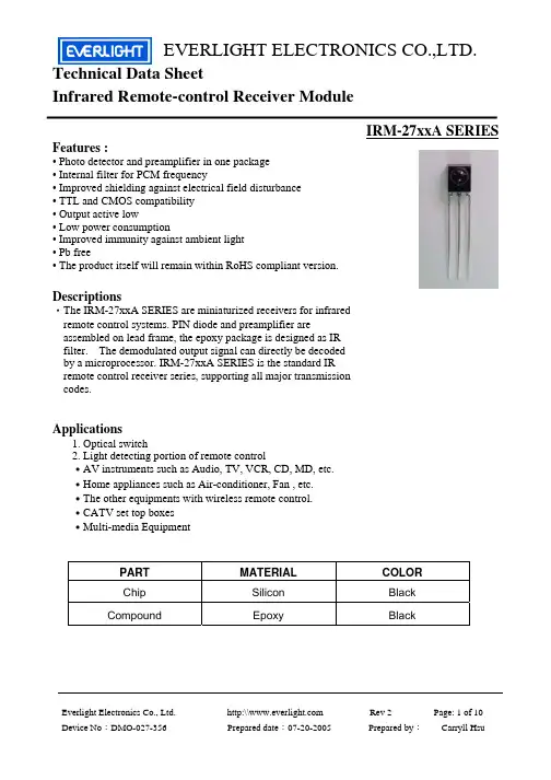
元器件交易网EVERLIGHT ELECTRONICS CO.,LTD.Technical Data Sheet Infrared Remote-control Receiver ModuleIRM-27xxA SERIESFeatures :• Photo detector and preamplifier in one package • Internal filter for PCM frequency • Improved shielding against electrical field disturbance • TTL and CMOS compatibility • Output active low • Low power consumption • Improved immunity against ambient light • Pb free • The product itself will remain within RoHS compliant version.Descriptions‧The IRM-27xxA SERIES are miniaturized receivers for infrared remote control systems. PIN diode and preamplifier are assembled on lead frame, the epoxy package is designed as IR filter. The demodulated output signal can directly be decoded by a microprocessor. IRM-27xxA SERIES is the standard IR remote control receiver series, supporting all major transmission codes.Applications1. Optical switch 2. Light detecting portion of remote control ․AV instruments such as Audio, TV, VCR, CD, MD, etc. ․Home appliances such as Air-conditioner, Fan , etc. ․The other equipments with wireless remote control. ․CATV set top boxes ․Multi-media EquipmentPART Chip CompoundMATERIAL Silicon EpoxyCOLOR Black BlackEverlight Electronics Co., Ltd. Device No:DMO-027-356http:\\ Prepared date:07-20-2005Rev 2 Prepared by:Page: 1 of 10 Carryll Hsu元器件交易网EVERLIGHT ELECTRONICS CO.,LTD.IRM-27xxA SERIESPackage DimensionsOUT Vcc GNDNotes: 1.All dimensions are in millimeters. 2.Tolerances unless dimensions ±0.3mm.Available Types For Different Carrier FrequenciesType IRM-2733A IRM-2736A IRM-2738A IRM-2740A IRM-2756A Carrier Frequencies(Typ) 32.7 kHz 36.7 kHz 37.9 kHz 40.0 kHz 56.7 kHzEverlight Electronics Co., Ltd. Device No:DMO-027-356http:\\ Prepared date:07-20-2005Rev 2 Prepared by:Page: 2 of 10 Carryll Hsu元器件交易网EVERLIGHT ELECTRONICS CO.,LTD.IRM-27xxA SERIESAbsolute Maximum Ratings (Ta=25℃)Parameter Supply Voltage Operating Temperature Storage Temperature Soldering Temperature Symbol Vcc Topr Tstg Tsol Rating 0~6 -25 ~ +80 -40 ~ +85 260 Unit V ℃ ℃ ℃ 4mm from mold body less than 10 seconds NoticeRecommended Operating ConditionSupply Voltage Rating: Vcc 4.5V to 5.5VElectro-Optical Characteristics (Ta=25℃, and Vcc=5 V)Parameter Consumption Current Peak Wavelength Reception Distance Half Angle(Horizontal) Half Angle(Vertical) High Level Pulse Width Low Level Pulse Width High Level Output Voltage Low Level Output Voltage Symbol Icc λp L0 L45 Θh Θv TH TL VH VL MIN. ----12 6 ----400 400 4.5 --TYP. 1.1 940 ----45 45 ------0.2 MAX. 2.5 ----------800 800 --0.5 deg deg μs μs V V At the ray axis *2 At the ray axis *1 Unit mA nm m Condition No signal input*1:The ray receiving surface at a vertex and relation to the ray axis in the range of θ= 0° and θ=45°. *2:A range from 30cm to the arrival distance. Average value of 50 pulses.Everlight Electronics Co., Ltd. Device No:DMO-027-356http:\\ Prepared date:07-20-2005Rev 2 Prepared by:Page: 3 of 10 Carryll Hsu元器件交易网EVERLIGHT ELECTRONICS CO.,LTD.IRM-27xxA SERIESTest Method:The specified electro-optical characteristics is satisfied under the following Conditions at the controllable distance. Measurement place A place that is nothing of extreme light reflected in the room. External light Project the light of ordinary white fluorescent lamps which are not high Frequency lamps and must be less then 10 Lux at the module surface. (Ee≦10Lux) Standard transmitter A transmitter whose output is so adjusted as to Vo=400mVp-p and the output Wave form shown in Fig.-1.According to the measurement method shown in Fig.-2 the standard transmitter is specified. However , the infrared photodiode to be used for the transmitter should be λp=940nm,∆λ=50nm. Also, photodiode is used of PD438B(Vr=5V). Measuring system According to the measuring system shown in Fig.-3Fig.-1Transmitter Wave FormD.U.T output PulseCarrier frequency is adjusted to center frequency of each product.OUTPUT PULSE OF DEVICEIR TANSMITTER OUTPUT WAVE FORMDuty=0.5Everlight Electronics Co., Ltd. Device No:DMO-027-356http:\\ Prepared date:07-20-2005Rev 2 Prepared by:Page: 4 of 10 Carryll Hsu元器件交易网EVERLIGHT ELECTRONICS CO.,LTD.IRM-27xxA SERIESFig.-2 Measuring Method20cm 10k +5.0± 0.1V 10uFθFig.-3Measuring SystemL: Transmission DistanceVccθOUT D.U.TStandard Transmitter Vout100kStandard TransmitterVout GNDθ: Angle Of Horizontal & Vertical DirectionOscilloscopeBlock Diagram:VCCVoltage Reference CircuitNoise Det.& Gain Ctrl.Band-pass FiterINI-V Converter &Input Bias ControlPre AmpAGC AmpLimit AmpComparatorIntegrator &Wave ShapingOutput StageOUTFset Bias Circuit Frequency Setting Frequency Trimming Threshold Control CircuitGNDApplication Circuit:RC Filter should be connected closely between Vcc pin and GND pin.Everlight Electronics Co., Ltd. Device No:DMO-027-356http:\\ Prepared date:07-20-2005Rev 2 Prepared by:Page: 5 of 10 Carryll Hsu元器件交易网EVERLIGHT ELECTRONICS CO.,LTD.IRM-27xxA SERIESThe Notice of Application:Transmission o remote control signal consist of four parts: Encode Part, IR Transmitter Source, IRM device, Decode Part 1. When IRM-27xxA code select frequency, it need to well understand the center system of encode part. 2. Strong or weak light of IR Transmitter can affect distance of transmission. 3. When using IRM-27xxA device, it requires the composition of code pattern to reach the demand as follows: Minimum Burst Length tburst (number of pulses per burst) : 10 cycles Minimum data pause time: Remocon TX code with Repeat key Remocon Tx code with Full frame RepeatRemocon TX repeat Code with minimum burst lengthTactual , data = Tdata − ∑ (TBn − 150 µs ) Tactual , gap = Tgap − ∑ (TBn − 150 µs )n nTgap ≥ 2.0 ∗ (Tr + 150 µs )Tactual , gap ≥ 2.0 ∗ Tactual ,data4. It needs to ensure the translation range of decode part if it is applied to the pulse-width range. If the above items hardly assure of its application, it’ll cause NG(no good) message from the edge of signal.Everlight Electronics Co., Ltd. Device No:DMO-027-356http:\\ Prepared date:07-20-2005Rev 2 Prepared by:Page: 6 of 10 Carryll Hsu元器件交易网EVERLIGHT ELECTRONICS CO.,LTD.IRM-27xxA SERIESTypical Electro-Optical Characteristics CurvesFig.-4 Relative Spectral Sensitivity vs. Wavelength Fig.-5 Relative Transmission Distance vs. DirectionθFig.-6 Arrival Distance vs. Ambient TemperatureFig.-7 Arrival Distance vs. Supply VoltageFig.-8 Relative Transmission Distance vs. Center Carrier Frequency IRM-2756A IRM-2733A, 2736A, 2738A, 2740ATWL ; Output Pulse Width (µsec)TWL ; Output Pulse Width (µsec)Transmission Distance Lc (m)Transmission Distance Lc (m)Everlight Electronics Co., Ltd. Device No:DMO-027-356http:\\ Prepared date:07-20-2005Rev 2 Prepared by:Page: 7 of 10 Carryll Hsu元器件交易网EVERLIGHT ELECTRONICS CO.,LTD.IRM-27xxA SERIESTypical Electro-Optical Characteristics CurvesFig.-9 Relative Transmission Distance vs. Center Carrier Frequency IRM-2733A IRM-2736ARelative Transmission Distance (%)Relative Transmission Distance (%)Relative Transmission Distance (%)IRM-2738ACenter Carrier Frequency (kHz)Center Carrier Frequency (kHz)Center Carrier Frequency (kHz)IRM-2740ARelative Transmission Distance (%)Relative Transmission Distance (%)IRM-2756ACenter Carrier Frequency (kHz)Center Carrier Frequency (kHz)Everlight Electronics Co., Ltd. Device No:DMO-027-356http:\\ Prepared date:07-20-2005Rev 2 Prepared by:Page: 8 of 10 Carryll Hsu元器件交易网EVERLIGHT ELECTRONICS CO.,LTD.IRM-27xxA SERIES█ Reliability Test Item And ConditionThe reliability of products shall be satisfied with items listed below. Confidence level: 90% LTPD: 10%Test ItemsTest Conditions 1 cycle -40℃ +25℃ +85℃ (30min)(5min)(30min) 300 cycle testFailure Judgement CriteriaSamples(n) Defective(c)Temperature cyclen=22,c=0Temp: +85℃ High temperature test Vcc:5V 1000hrs Low temperature storage High temperature High humidity Temp: -40℃ 1000hrs Ta: 85℃,RH: 85% 1000hrs Temp: 260±5℃ 10sec 4mm From the bottom of the package.n=22,c=0 L0≦ L×0.8 L45≦ L×0.8 n=22,c=0 L: Lower specification limit n=22,c=0Solder heatn=22,c=0Everlight Electronics Co., Ltd. Device No:DMO-027-356http:\\ Prepared date:07-20-2005Rev 2 Prepared by:Page: 9 of 10 Carryll Hsu元器件交易网EVERLIGHT ELECTRONICS CO.,LTD.IRM-27xxA SERIESPacking Quantity Specification1. 1500PCS/1Box 2. 10Boxes/1CartonLabel Form SpecificationCPN: Customer’s Production Number P/N : Production Number QTY: Packing Quantity CAT: Ranks HUE: Peak Wavelength REF: Reference LOT No: Lot Number MADE IN TAIWAN: Production PlaceRoHSIRM-2738ANotes1. Above specification may be changed without notice. EVERLIGHT will reserve authority on material change for above specification. 2. When using this product, please observe the absolute maximum ratings and the instructions for using outlined in these specification sheets. EVERLIGHT assumes no responsibility for any damage resulting from use of the product which does not comply with the absolute maximum ratings and the instructions included in these specification sheets. 3. These specification sheets include materials protected under copyright of EVERLIGHT corporation. Please don’t reproduce or cause anyone to reproduce them without EVERLIGHT’s consent.EVERLIGHT ELECTRONICS CO., LTD. Office: No 25, Lane 76, Sec 3, Chung Yang Rd, Tucheng, Taipei 236, Taiwan, R.O.CTel: 886-2-2267-2000, 2267-9936 Fax: 886-2267-6244, 2267-6189, 2267-6306 http:\\Everlight Electronics Co., Ltd. Device No:DMO-027-356http:\\ Prepared date:07-20-2005Rev 2 Prepared by:Page: 10 of 10 Carryll Hsu。

Technical Data SheetInfrared Remote-control Receiver ModuleIRM-H538/TR2 Features‧High shielding against electric field disturbance.‧Circular lens to improve the receive characteristic.‧Line-up for various center carrier frequencies.‧Low voltage and low power consumption.‧High immunity against ambient light.‧Photodiode with integrated circuit.‧TTL and CMOS compatibility.‧Top-received SMD.‧Suitable burst length ≧10 pulses/burst.‧This product itself will remain within RoHS compliant version.‧Pb free.‧External dimensions 5.3(L)*2.9(W)*3.65(H)mm.DescriptionsThe device is a miniature SMD type infrared remotecontrol system receiver that has been developed anddesigned by utilizing the most updated IC technology. ThePIN diode and preamplifier are assembled on PCB, theepoxy package is designed as an IR filter. The demodulatedoutput signal can directly be decoded by a microprocessor.Applications1. Light detecting portion of remote control․AV instruments such as Audio, TV, VCR, CD, MD, etc.․Home appliances such as Air-conditioner, Fan , etc.․The other equipments with wireless remote control.․CATV set top boxes․Multi-media EquipmentDevice Selection GuidePART MATERIAL COLORChip Silicon ---Package Epoxy BlackMetal case SPCC Silver whiteIRM-H538/TR2 Absolute Maximum Ratings (Ta=25℃)Parameter Symbol Rating Unit Notice Supply Voltage Vcc 0~6 VOperating Temperature Topr -25 ~ +85 ℃Storage Temperature Tstg -40 ~ +85 ℃Recommended Operating ConditionSupply Voltage Rating: Vcc 2.7V to 5.5VElectro-Optical Characteristics (Ta=25℃, and Vcc=3.0V)Parameter Symbol MIN. TYP. MAX. Unit Condition Supply Current Icc --- --- 1.2 mA No signal input Peak Wavelength λp--- 940 --- nmL08 --- ---Reception DistanceL45 5 --- ---mHalf Angle(Horizontal) Θh--- 45 --- deg At the ray axis*1Half Angle(Vertical) Θv--- 45 --- degHigh Level Pulse Width T H400 --- 800 μs Low Level Pulse Width T L400 --- 800 μs At the ray axis*2High Level Output Voltage V H 2.7 --- --- VLow Level Output Voltage V L--- 0.2 0.5 VNotes:*1:The ray receiving surface at a vertex and relation to the ray axis in the range of θ= 0° and θ=45°. *2:A range from 30cm to the arrival distance. Average value of 50 pulses.IRM-H538/TR2 The Notice of Application:Transmission remote control signal consist of four parts: Encode Part, IR Transmitter Source, IRM device, Decode Part1. When IRM-H538 code select frequency, it need to well understand the center system ofencode part.2. Strong or weak light of IR Transmitter can affect distance of transmission.3. Minimum Burst Length T burst (number of pulses per burst) : 10 cycles4. It needs to ensure the translation range of decode part if it is applied to the pulse-width range. If the above items hardly assure of its application, it’ll cause NG(no good) message from the edge of signal.Test Method:The specified electro-optical characteristics is satisfied under the followingConditions at the controllable distance.Measurement placeA place that is nothing of extreme light reflected in the room.External lightProject the light of ordinary white fluorescent lamps which are not highFrequency lamps and must be less then 10 Lux at the module surface.(Ee≦10Lux)Standard transmitterIRM-H538/TR2IRM-H538/TR2Fig.-6 Output Pulse Length vs. Arrival Distance Fig.-7 Arrival Distance vs. Supply VoltageIRM-H538/TR2 Typical Electro-Optical Characteristics CurvesIRM-H538/TR2Reliability Test Item And ConditionThe reliability of products shall be satisfied with items listed below.Confidence level:90%LTPD:10%Reflow Terms: JEDEC Level 4 SpecificationDrying; Temp.:125℃24hrs Moisture 30℃/ 60% RH 96hrs Reflow Temp.: 260℃±5℃10sec, 3 timesNote:1. Not sooner than 15 minutes and not longer than 4 hours after removal from thetemperature/humidity chamber.2. The time between reflow shall be 5 minutes minimum and 60 minutes maximum.Test Items Test Conditions Failure JudgementCriteriaSamples(n)Defective(c)Temperature cycle 1 cycle:-25℃+85℃(30min)(5min)(30min)300 cycle testn=76,c=0High temperature test Temp:+85℃Vcc:5V1000hrsn=76,c=0Low temperature storage Temp:-40℃1000hrsn=76,c=0High temperature High humidity Ta:85℃,RH:85%1000hrsL0≦L×0.8L45≦L×0.8L: Lowerspecification limit*Icc : OperateCurrent (mA)Variation≦±20%:n=76,c=0IRM-H538/TR2 Recommended method of storageDry box storage is recommended as soon as the aluminum bag has been opened prevent moisture absorption. The following conditions should be observed, if dry boxes are not available:Storage temperature 10℃to 30℃Storage humidity ≦60%RH max.After more than 72 hours under these conditions moisture content will be too high for Reflow soldering:In case of moisture absorption, the devices will recover to former condition by drying under the following condition:192 hours at 40℃+5℃/-0℃and 5%RH (dry air / nitrogen) or96 hours at 60℃+5℃and < 5%RH for all device containers or24 hours at 125℃+5℃not suitable for reel or tubes.ESD PrecautionProper storage and handing procedures should be followed to prevent ESD damage tothe devices especially when they are removed from the Anti-static bag. Electro-Static Sensitive Devices warning labels are on the packing.Recommended Solder Profile(1) Reflow soldering should not be done more than two times.(2) When soldering, do not put stress on the IRM-H538/TR1 Series devices during heating.(3) After soldering, do not warp the circuit board.IRM-H538/TR2 Soldering IronEach terminal is to go to the tip of soldering iron temperature less than 350℃for 3 seconds within once in less than the soldering iron capacity 25W. Leave two seconds and more intervals, and do soldering of each terminal. Be careful because the damage of the product is often started at the time of the hand solder.RepairingRepair should not be done after the Devices have been soldered. When repairing is unavoidable, a double-head soldering iron should be used (as below figure). It should be confirmed分销商库存信息: EVERLIGHTIRM-H538/TR2。
完美替代HS0038B的红外线接收模块-IRM38BL-2万州光电生产的IRM38BL-2是一个完美的替代方案,在某些性能,比如抗干扰能力上完全超越HS0038BIRM38B系列红外线接收模块的受光面一侧为黑色环氧树脂聚焦滤波透镜,此透镜消除了可见光对它的干扰,对于提高可靠性及滤除光噪声至关重要。
模块内含红外线PIN接收管,前置放大器和解调器。
当红外线发射管发出的信号经空间传送到IRM38B系列红外线接收模块时,模块内部PIN红外线接受管将红外光转换为电信号,该信号经前置放大、解调后由3脚输出与TTL电平兼容的电信号,该信号能直接送入到微控制器等要求TTL电平信号输入的芯片中。
红外接收头内部放大器的增益很大,很容易引起干扰,因此在接收头的供电脚上须加上滤波电容,一般在22uf以上。
有的厂家建议在供电脚和电源之间接入330欧电阻,进一步降低电源干扰。
红外线接收器生产厂家红外线接收器是我们俗称的红外接收头,他是一个高灵敏度的红外接收元件。
红外线接收器借助一种内部金属屏蔽和智能自动增益放大电路,可以有效抑制太阳和可能存在于接收器使用环境的节能灯等设备所发出的其它形式的干扰中辨别出红外信号,从而达到抗干扰的目的。
红外接收器广泛用于多媒体设备,如交互式TV机顶盒、视频会议系统、游戏控制器、交互式玩具以及无线键盘和鼠标中。
市场主导标准频率范围30-56kHz。
使用最多的是38KHZ。
哪种红外接收头好?我们有句俗话:只买对的不买贵的,红外接收头的选择同样如此,比如,你需要一个遥控距离是2米的红外接收头,却选择了一款遥控距离是20米的红外接收头,当然后者的价格肯定要贵一些,所以,你为什么要花钱买后者呢?如果你的产品附加值很高,你想为客户提供非常好的使用体验,甚至特殊情况下,本来要求遥控2米,结果20米都能遥控,当然更好。
那么什么样的红外接收头最好?首先是品牌万州威世亿光品牌红外接收头带来的不仅是质量上的保证,也是产品在使用过程中能够得到更多的服务,出了问题能够得到的及时有效的解决方案。