
IRM-3638F4中文资料
- 格式:pdf
- 大小:228.40 KB
- 文档页数:7


赛默飞近红外参数【实用版】目录一、赛默飞近红外光谱仪的概述二、赛默飞近红外光谱仪的参数1.Nicolet iS 5N2.Trudefender 手持红外光谱仪三、赛默飞近红外光谱仪的应用领域四、赛默飞近红外光谱仪的优势五、结语正文一、赛默飞近红外光谱仪的概述赛默飞近红外光谱仪是一款高性能的光谱分析仪器,能够对样品进行近红外区域的光谱分析,被广泛应用于各个领域,如化学、生物学、医学、环境监测等。
赛默飞作为全球知名的科学仪器制造商,在近红外光谱仪领域有着丰富的经验和技术积累。
二、赛默飞近红外光谱仪的参数1.Nicolet iS 5Nicolet iS 5N 是赛默飞一款先进的近红外光谱仪,具有高分辨率、高灵敏度和快速扫描等特点。
其主要参数如下:- 波长范围:0.9μm ~ 1.7μm- 分辨率:≤0.5cm^-1- 灵敏度:≤0.001g/mL- 扫描速度:≤1s/点2.Trudefender 手持红外光谱仪Trudefender 是赛默飞一款手持式近红外光谱仪,具有便携、易操作和实时分析等特点。
其主要参数如下:- 波长范围:0.9μm ~ 1.7μm- 分辨率:≤1.5cm^-1- 灵敏度:≤0.01g/mL- 扫描速度:≤2s/点- 重量:≤3kg三、赛默飞近红外光谱仪的应用领域赛默飞近红外光谱仪广泛应用于各种领域,如生物医学、化学化工、食品饮料、环境和材料科学等。
在生物医学领域,可以用于蛋白质结构分析、疾病诊断和生物分子识别等;在化学化工领域,可以用于分子结构分析、化学反应监测和产品质量控制等;在食品饮料领域,可以用于成分分析、品质控制和食品安全监测等。
四、赛默飞近红外光谱仪的优势赛默飞近红外光谱仪具有以下优势:1.高分辨率和高灵敏度,能够对样品进行精确分析。
2.快速扫描和实时分析,能够提高分析效率。
3.便携式设计,便于携带和现场分析。
4.丰富的应用经验和技术支持,确保分析结果的准确性。
五、结语赛默飞近红外光谱仪凭借其优异的性能和广泛的应用领域,在光谱分析领域具有重要地位。
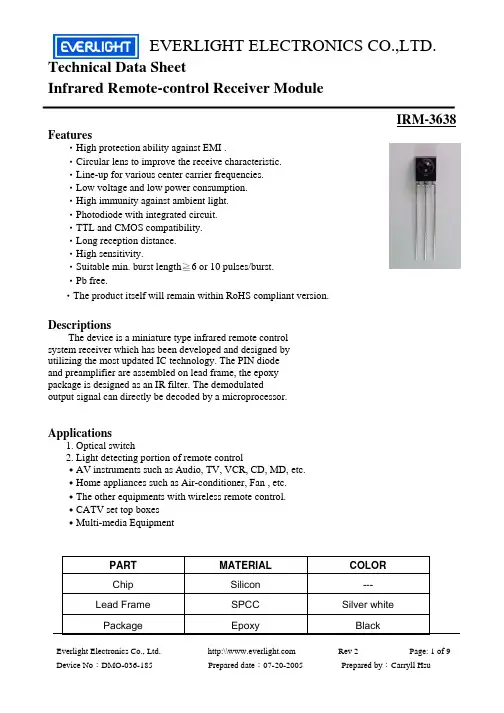
元器件交易网EVERLIGHT ELECTRONICS CO.,LTD.Technical Data Sheet Infrared Remote-control Receiver ModuleIRM-3638Features‧High protection ability against EMI . ‧Circular lens to improve the receive characteristic. ‧Line-up for various center carrier frequencies. ‧Low voltage and low power consumption. ‧High immunity against ambient light. ‧Photodiode with integrated circuit. ‧TTL and CMOS compatibility. ‧Long reception distance. ‧High sensitivity. ‧Suitable min. burst length≧6 or 10 pulses/burst. ‧Pb free. ‧The product itself will remain within RoHS compliant version.DescriptionsThe device is a miniature type infrared remote control system receiver which has been developed and designed by utilizing the most updated IC technology. The PIN diode and preamplifier are assembled on lead frame, the epoxy package is designed as an IR filter. The demodulated output signal can directly be decoded by a microprocessor.Applications1. Optical switch 2. Light detecting portion of remote control ․AV instruments such as Audio, TV, VCR, CD, MD, etc. ․Home appliances such as Air-conditioner, Fan , etc. ․The other equipments with wireless remote control. ․CATV set top boxes ․Multi-media EquipmentPART Chip Lead Frame PackageEverlight Electronics Co., Ltd. Device No:DMO-036-185MATERIAL Silicon SPCC Epoxyhttp:\\ Prepared date:07-20-2005COLOR --Silver white BlackRev 2 Page: 1 of 9Prepared by:Carryll Hsu元器件交易网EVERLIGHT ELECTRONICS CO.,LTD.IRM-3638Package DimensionsOUT GND VccNotes: 1.All dimensions are in millimeters. 2.Tolerances unless dimensions ±0.3mm.Absolute Maximum Ratings (Ta=25℃)Parameter Supply Voltage Operating Temperature Storage Temperature Soldering Temperature Symbol Vcc Topr Tstg Tsol Rating 6 -25 ~ +85 -40 ~ +85 260 Unit V ℃ ℃ ℃ 4mm from mold body less than 10 seconds NoticeEverlight Electronics Co., Ltd. Device No:DMO-036-185http:\\ Prepared date:07-20-2005Rev 2Page: 2 of 9Prepared by:Carryll Hsu元器件交易网EVERLIGHT ELECTRONICS CO.,LTD.IRM-3638Recommended Operating ConditionSupply Voltage Rating: Vcc 2.7V to 5.5VElectro-Optical Characteristics (Ta=25℃, and Vcc=3.0V)Parameter Consumption Current B.P.F Center Frequency Peak Wavelength Reception Distance Half Angle(Horizontal) Half Angle(Vertical) High Level Pulse Width Low Level Pulse Width High Level Output Voltage Low Level Output Voltage Symbol Icc Fo λp L0 L45 Θh Θv TH TL VH VL MIN. ------14 6 ----400 400 2.7 --TYP. --38 940 ----45 45 ------0.2 MAX. 2 ------------800 800 --0.5 deg deg μs μs V V At the ray axis *2 At the ray axis *1 Unit mA KHz nm m Condition No signal inputNotes: *1:The ray receiving surface at a vertex and relation to the ray axis in the range of θ= 0° and θ=45°. *2:A range from 30cm to the arrival distance. Average value of 50 pulses.Everlight Electronics Co., Ltd. Device No:DMO-036-185http:\\ Prepared date:07-20-2005Rev 2Page: 3 of 9Prepared by:Carryll Hsu元器件交易网EVERLIGHT ELECTRONICS CO.,LTD.IRM-3638Test Method:The specified electro-optical characteristics is satisfied under the following Conditions at the controllable distance. Measurement place A place that is nothing of extreme light reflected in the room. External light Project the light of ordinary white fluorescent lamps which are not high Frequency lamps and must be less then 10 Lux at the module surface. (Ee≦10Lux) Standard transmitter A transmitter whose output is so adjusted as to Vo=400mVp-p and the output Wave form shown in Fig.-1.According to the measurement method shown in Fig.-2 the standard transmitter is specified. However , the infrared photodiode to be used for the transmitter should be λp=940nm,∆λ=50nm. Also, photodiode is used of PD438B(Vr=5V). (Standard light / Light source temperature 2856°K). Measuring system According to the measuring system shown in Fig.-3Block Diagram:VsIN Input CGA & filter DemodulatorOUT µCOscillatorCarrier frequency f0AGC/ATC & digital controlModulated IR signal min 6/10 pulsesGNDEverlight Electronics Co., Ltd. Device No:DMO-036-185http:\\ Prepared date:07-20-2005Rev 2Page: 4 of 9Prepared by:Carryll Hsu元器件交易网EVERLIGHT ELECTRONICS CO.,LTD.IRM-3638Application Circuit:RC Filter should be connected closely between Vcc pin and GND pin.Fig.-1Transmitter Wave FormD.U.T output PulseCarrier frequency is adjusted to center frequency of each product.OUTPUT PULSE OF DEVICEIR TANSMITTER OUTPUT WAVE FORMDuty=0.5Fig.-2Measuring Method20cm 10k +5.0± 0.1VFig.-3Measuring SystemL: Transmission Distance10uFθ θVcc OUT D.U.TVoutStandard TransmitterStandard Transmitter100kVout GNDOscilloscopeθ: Angle Of Horizontal & Vertical DirectionEverlight Electronics Co., Ltd. Device No:DMO-036-185http:\\ Prepared date:07-20-2005Rev 2Page: 5 of 9Prepared by:Carryll Hsu元器件交易网EVERLIGHT ELECTRONICS CO.,LTD.IRM-3638Typical Electro-Optical Characteristics CurvesFig.-4 Relative Spectral Sensitivity vs. Wavelength Fig.-5 Relative Transmission Distance vs. DirectionθFig.-6 Output Pulse Length vs. Arrival DistanceFig.-7 Arrival Distance vs. Supply Voltage17.5 14.0 10.5 7.0 3.5Everlight Electronics Co., Ltd. Device No:DMO-036-185http:\\ Prepared date:07-20-2005Rev 2Page: 6 of 9Prepared by:Carryll Hsu元器件交易网EVERLIGHT ELECTRONICS CO.,LTD.IRM-3638Typical Electro-Optical Characteristics CurvesFig.-8 Relative Transmission Distance vs. Center Carrier Frequency Fig.-9 Arrival Distance vs. Ambient Temperature17.5Transmission Distance Lc (m)14.0 10.5 7.0 3.5Ambient Temperature Ta (°C)Everlight Electronics Co., Ltd. Device No:DMO-036-185http:\\ Prepared date:07-20-2005Rev 2Page: 7 of 9Prepared by:Carryll Hsu元器件交易网EVERLIGHT ELECTRONICS CO.,LTD.IRM-3638Reliability Test Item And ConditionThe reliability of products shall be satisfied with items listed below. Confidence level:90% LTPD:10% Test Items Test Conditions 1 cycle Temperature cycle -25℃ +85℃ n=22,c=0 Failure Judgement Criteria Samples(n) Defective(c)(30min)(5min)(30min) 300 cycle test Temp: +85℃High temperature test Vcc:5V 1000hrs Low temperature storage High temperature High humidity Temp: -40℃ 1000hrs Ta: 85℃,RH:85% 1000hrs Temp: 260±5℃ 10sec 4mm From the bottom of the package.L0≦ L×0.8 L45≦ L×0.8n=22,c=0n=22,c=0 L: Lower specification limit n=22,c=0Solder heatn=22,c=0Everlight Electronics Co., Ltd. Device No:DMO-036-185http:\\ Prepared date:07-20-2005Rev 2Page: 8 of 9Prepared by:Carryll Hsu元器件交易网EVERLIGHT ELECTRONICS CO.,LTD.IRM-3638Packing Quantity Specification1. 1500 PCS/1Box 2. 10 Boxes/1CartonLabel Form SpecificationCPN: Customer’s Production Number P/N : Production Number QTY: Packing Quantity CAT: Ranks HUE: Peak Wavelength REF: Reference LOT No: Lot Number MADE IN TAIWAN: Production PlaceIRM-3638Notes1. Above specification may be changed without notice. EVERLIGHT will reserve authority on material change for above specification. 2. When using this product, please observe the absolute maximum ratings and the instructions for using outlined in these specification sheets. EVERLIGHT assumes no responsibility for any damage resulting from use of the product which does not comply with the absolute maximum ratings and the instructions included in these specification sheets. 3. These specification sheets include materials protected under copyright of EVERLIGHT corporation. Please don’t reproduce or cause anyone to reproduce them without EVERLIGHT’s consent.EVERLIGHT ELECTRONICS CO., LTD. Office: No 25, Lane 76, Sec 3, Chung Yang Rd, Tucheng, Taipei 236, Taiwan, R.O.CTel: 886-2-2267-2000, 2267-9936 Fax: 886-2267-6244, 2267-6189, 2267-6306 http:\\Everlight Electronics Co., Ltd. Device No:DMO-036-185http:\\ Prepared date:07-20-2005Rev 2Page: 9 of 9Prepared by:Carryll Hsu。

IRM-36xxM 3F45 seriesFeatures‧High protection ability against EMI‧Circular lens for improved reception characteristics ‧Available for various carrier frequencies ‧Min burst length: 6 cycles ‧Min gap length: 10 cycles ‧Suitable for continuous code‧Low operating voltage and low power consumption Optimized immunity against TFT backlight ‧interferences ‧High immunity against ambient light ‧Long reception range ‧High sensitivity‧Pb free and RoHS compliantDescriptionThe IRM-36xxM 3F45 series devices are miniature type infrared receivers which have been developed and designed by using the latest IC technology, specially optimized to suppress interferences from TFT backlight.The photo diode and preamplifier are assembled onto a lead frame and molded into an epoxy package which operates as an IR filter.The demodulated output signal can directly be decoded by a microprocessor.Applications• AV equipment such as TV, VCR, DVD, CD, MD, etc.• Short pause time protocols • Toy applications • CATV set top boxes • Multi-media Equipment• Other devices using IR remote controlApplication Circuit Block DiagramPin Configuration 1.OUT 2.GND 3.V123IRM-36xxM3F45 seriesThe RC Filter must be connected as close as possible toVcc and GND pins.Parts TableModel No.Carrier FrequencyIRM-3636M3F4536 kHzIRM-3638M3F4538 kHzIRM-3640M3F4540 kHzPackage Dimensions(Dimensions in mm)IRM-36xxM3F45 seriesNotes:Tolerances unless dimensions ±0.3mm.Absolute Maximum Ratings (T a=25°C)Parameter Symbol Rating UnitSupply Voltage Vcc6VOperating Temperature Topr-20 ~ +80Storage Temperature Tstg-40 ~ +85IRM-36xxM3F45 seriesSoldering Temperature *1Tsol260*1 4mm from mold body for less than 10 secondsElectro-Optical Characteristics (Ta=25 , Vcc=3V)Parameter Symbol MIN.TYP.MAX.Unit ConditionCurrent consumption Icc---0.40.6mA No input signal Supply voltage V CC 2.7- 5.5VPeak wavelengthλp---940---nmReception range L014------mSee chapter‚Test method’L456------Half angle(horizontal)φh---±35---degHalf angle(vertical)φv---±35---degHigh level pulse width T H450---700μs Test signalaccording tofigure 1Low level pulse width T L500---750μsHigh level output voltage V OH Vcc-0.4------V I SOURCE 1μA Low level output voltage V OL---0.20.5V I SINK 2mA Internal pull up resistor R PU85100115kΩTest methodThe specified electro-optical characteristics are valid under the following conditions.1.Measurement environmentA place without extreme light reflections.2.External lightThe environment contains an ordinary, white fluorescent lamp without high frequency modulation. The color temperature is 2856K and the illumination at the IR receiver is less than 10 Lux (Ev 10Lux).3.Standard transmitterThe test transmitter is calibrated by transmitter is adjusted until Vo=400wavelength of 940nm. The photo dio 4.The measurement system is shown Fig.-1 Transmitter Wave F Fig.-2 standard transmitte TypicalElectro-Optical Charac d by using the circuit shown in figure 2. The radiation =400mVp-p. Both,the test transmitter and the photo d oto diode for calibration is PD438B (λp=940nm,Vr=5V hown in Fig.-3ave FormD.U.T out mitter calibration Fig.-3 Mea haracteristicCurvesIRM-36xxM 3F45 seriesation intensity of the hoto diode,have a peak r=5V).T output PulseMeasuring SystemIRM-36xxM3F45 seriesIRM-36xxM3F45 series Code informationProtocol Suitable Protocol SuitableJVC Yes RCA YesMatsushita Yes Sharp YesMitsubishi Yes Sony 12 Bit YesNEC Yes Sony 15 Bit NoRC5Yes Sony 20Bit NoRC6Yes Toshiba YesRCMM Yes Zenith YesRCS-80Yes Continuous Code YesDevice MarkingNotes1 denotes Year code2 denotes Month code3 denotes Device number4denotes Carrier frequency(2: 36KHz, 4: 38KHz and 5: 40KHz)Packing Quantity1500 pcs / Box10 Boxes / CartonIRM-36xxM3F45 series DISCLAIMER1.Above specification may be changed without notice. EVERLIGHT will reserve authority on materialchange for above specification.2.When using this product, please observe the absolute maximum ratings and the instructions for useoutlined in these specification sheets. EVERLIGHT assumes no responsibility for any damage resulting from use of the product which does not comply with the absolute maximum ratings and the instructions included in these specification sheets.3.These specification sheets include materials protected under copyright of EVERLIGHT. Reproduction inany form is prohibited without the specific consent of EVERLIGHT.。

紅外接收器(Infrared Receiver Module; IRM)應用手冊一、簡介:在地球上充滿了各種波長的電磁波,所謂的可見(色)光就是人眼可見的電磁波譜,其波長為380~770nm,為了避免遙控器發射的光造成人眼不適及減少一般人造光源干擾,故選用人眼不可見的紅外線(Infrared)波長,目前業界遙控器發射頭幾乎都選用940nm波長。
圖一、電磁波波長分類紅外線遙控器的應用也是一種無線訊號傳輸,跟大部分的無線傳輸技術一樣,為了避免環境中同波長電磁波的干擾,故會在其傳輸訊號上加上如圖二所示的載波(carrier frequency),在遙控應用的載波範圍為30~60kHz,而38kHz為最常見的載波頻率。
圖二、紅外線發射訊號定義二、使用說明:一般紅外遙控系統除了載波外,還有通訊協定(IR protocol),不同的IRM能支援的協定均不相同;在選用IRM前,請先參考規格書中如表一的支援協定列表是否支援,另須注意協定的載波頻率和IRM型號是否匹配(億光IRM產品不同頻率但相同晶片的IRM型號會共用規格書)。
IRM載波頻率在出廠時就會燒定,若選擇38kHz中心頻率的IRM,也可接收36kHz 或40KHz的紅外通訊協定,但接收距離會較38kHz載波頻率的協定短,故選擇正確中心頻率的IRM才能得到最佳接收距離,各型號IRM能選擇的中心頻率請參考規格書中如圖三、支援載波頻率及相對靈敏度。
1.) 有支援的紅外協定都可支援長按(repeat)操作。
2.) Continuous Code一般指的是Pause time小於10ms的連續發射訊號。
圖三、支援載波頻率及相對靈敏度一般的IRM是無法一直連續的接收載波訊號,除了圖二定義的休息時間較短的gap time(通常1ms以下),每經過一組完整數據(Data)還需有休息時間較長的Pause time(10ms以上),故若使用的紅外協定沒有列在規格書的表中或有特殊考量需使用自訂的協定,須注意如底下規格書所列的最小需求(每個型號不同,需看相對應型號的規格書)。