elvax_250[1]
- 格式:pdf
- 大小:54.58 KB
- 文档页数:2

/ Battery Charging Systems / Welding Technology/ Solar Electronics MANUAL WELDING/ Product GuideF ro n iu s W e ld in g T e ch n o lo g yN o w A v a il a b le f ro mF ro n iu s U K, M il to n K e y n e sMIG/MAG TIG MMA PlasmaProtective EquipmentContents****************************************MIG/MAGThe TransSteel 3500/5000 and nowthe 3500 compact version embodyan intelligent industrial design,service life. This digitally controlledMIG/MAG welding system comeswith Steel Transfer Technology togive you optimum steel weldingThe TransSteel is a rugged and reliable partner that stands outfor its intelligent appliance design and ease of operation.Digitally controlled and primed with the expert knowledgepackage, “Steel Transfer Technology,” specifically put togetherfor the steel market, the TransSteel ensures the very greatestTransSteel 3500 TransSteel 50005TransSynergic 4000 /4000 C / 5000 / 5000 CM I G /M A GProcessesMIG/MAG welding Electrode weldingThe Compact version of the TransSteel 3500 comes fitted out with all the details that make life easier for structural steel fabricators. As a space-saving yet powerful version of the TransSteel series, the Compact model is of particular interest to workshop operations. Its integrated wirefeeder is another feature making the TransSteel 3500 Compact a good-value option for operations with more limited resources.The fully digitised and microprocessor-controlled MIG/MAG power source for short circuit arcs and spray arcs enables the best weld properties in every respect, and reproducible results time and time again.4000 MV 5000 MW 5000ProcessesMIG/MAG welding, Mig-brazing, TIG-DC (C-version),Manual electrode (MMA) welding (C-version),Arc air gouging (TS 5000 C)Recommended Base MaterialsConstructional steels, Coated constructional steels, Ferritic / austenitic CrNi steels, Duplex-steels, Nickel-based materials, Aluminium materials6TPS 2700 / 2700 TIG / 2700 Duo / 2700 Duo TIGThe TransPuls Synergic 2700 for short circuit, spray and pulsedarcs is a fully digitised and microprocessor-controlled MIG/MAG power source with an output of 270 A. The power sourcegives the best weld properties in every respect, andreproducible results time and time again. The integral wire-feedunit guarantees portable use on construction sites, inworkshops and for maintenance and repair activities.Recommended Base MaterialsConstructional steels, Coated constructional steelsFerritic / austenitic CrNi steels, Duplex-steels, Nickel-basedmaterials, Aluminium materials, Special materialsProcessesMIG/MAG welding, MIG/MAG impulsed arc welding, MIGbrazing, TIG-DC, Manual electrode (MMA) welding7TPS 3200 / 4000 / 5000Pulse welding with up to 500 A, highest precision, exact reproducibility and best weld properties, anytime, anywhere. The multiprocess powersource is suitable for MIG/MAG, TIG and electrode welding, as well as manual or robotic applications.Recommended base materialsConstructional steels, Coated constructional steels, Ferritic / austenitic CrNi steels, Duplex-steels, Nickel-based materials, Aluminium materials, Special materials, Copper materials (TPS 5000), Magnesium materials (TPS 5000)ProcessesMIG welding, MIG pulsed arc welding, MIG brazing, TIG-DC, Manual electrode welding, Arc air gouging (TPS 5000)M I G /M A G899% Less Spatter | Ultra High Precision ProcessCMT stands for Cold Metal Transfer. The wire movement isincorporated into the process control, where heat is inserted only very briefly. Metal transfer takes place with barely any flow of current. The result is spatter-free MIG/MAG welding and brazing of thin sheets (0.3 mm or thicker), MIG brazing of galvanised sheets and the joining of steel and aluminium.Recommended base materialsConstructional steels, Coated constructional steels, CrNi steels, Nickel-based materials, Aluminium materials, Special materials, Magnesium materials, Copper materialsProcessesCMT brazing, CMT welding, MIG welding, MIG pulsed arc weldingTIME 5000 DIGITALM GU p t d e p o s i t i o n r a t e so n s t e e l s .P a t e n t e d F r o n i u sT e c h n o l o g y9Wire feed units for VR4000 / VR5000 / VR7000VR 4000-22/-30VR 7000-22/-11/-30VR 5000TPS Steel/ The TPS Steel comes with special characteristics for the steel user segment that can be adjusted quickly and easily via the control panel. This fully digitised welding system makes for superlative welding properties, in every respect, and for results that are replicable any number of times. In either standard or pulsed-arc welding, the TPS Steel is a dependable partner in both manual and automated applications.Dimensions (HxWxLmm)WeightMains Frequency Mains Fuse Protection Class Open-circuit Voltage Mains Voltage (+/-10%)Operating VoltageWelding Current / Duty Cycle (10min/40C)Min-max. Welding currentTPS 3200475x290x625320A 365A / 60% 400A / 50%10M I G /M A G A c c e s s o r i e sRemote control units for digital machinesTR 1000TR 1100TR 1200TR 1300TR 1600TR 2000TR 2100TR 2200 F11M I G /M A G A c c e s s o r i e sRemote control units continuedTR 2200-FM TR 3000TR 4000 CTR 4000 RCU 4000RCU 5000i12M I G /M A G A C C E S S O R I ES M I G /M A G A c c e s s o r i e s Cooling Units MIG/MAGFK 3000RFK 4000 FK 4000 R FK 4000 R FC FK 4000 ROBFK 5000FK 6000FK 9000 RThere are many options available for this product. Please call one of our sales representatives for more details on 01908 512 300.13AL2300 / 3000 / 4000 / 5000 Standard, Up/Down, JobMasterM I G /M A G T o r c h e sContact tube, CuCrZr alloy Coaxial cableRubber anti-kink feature at machine and torch endStandard Equipment - Jobmaster onlyIntegrated remote control Frequency parameter recall Parameter correction modeRecall function for operating points and jobs Digital parameter display14AW2500 / 4000 / 5000 / 7000 Standard, Up/Down, JobMasterProcessesMIG/MAG weldingMIG/MAG pulsed arc welding MIG brazingRecommended base materialsConstructional steelsCoated constructional steels Ferritic / ausenitic CrNi steels Duplex steelsNickel based materials Aluminium materials Magnesium materials Copper materialsMultilock-SystemStandard EquipmentTorch body:Spatter protection with high thermal stability Forced contacting arrangement for welding wire Torch neck rotates through 360°Hose pack:Steel inner liner for steel wire Swivel mounted protective hoseCoaxial cable at gas cooled welding torchRubber anti-kink feature at machine and torch endM I G /M A G T o r c h e s15ProcessesMIG/MAG weldingMIG/MAG pulsed arc welding with water-cooled torchesMIG brazingRecommended base materialsConstructional steelsCoated constructional steels Ferritic / austenitic CrNi steels Duplex-steelNickel-based materials Aluminium materials Magnesium materialsCopper materialsTime / Time Multilock / AW5000 Time /AW7000 TimeProcessesMIG/MAG welding, MIG/MAG pulsed arc welding,MIG/MAG high performance welding, MIG brazingRecommended base materialsConstructional steelsCoated constructional steels Ferritic / austenitic CrNi steels Duplex-steelsNickel-based materials Aluminium materialsM I G /M A G T o r c h e sPullMig CMT hose packPullMig hose packs / PullMig JobMaster hose packsProcessesCMT brazing, CMT welding, CMT pulsed arc welding, MIG/MAG welding, MIG brazingRecommended base materialsConstructional steels, Coated constructional steels,Ferritic / austenitic CrNi steels,Duplex-steels, Nickel-based materials,Aluminium materials, Special materials,Magnesium materials, Copper materialsProcessesMIG/MAG welding, MIG/MAG pulsed arc welding with water cooled torches, MIG brazingRecommended base materialsConstructional steels, Coated constructional steels,Ferritic / austenitic CrNi steels, Duplex-steels,Nickel-based materials Aluminium materials Magnesium materials Copper materialsM I G /M A G T o r c h e s16MTG3500 S / MTG5000 S / MTG5300 S Standard, Up/Down(manual welding torch for TransSteel)ProcessesMIG/MAG weldingRecommended base materialsSteelMTW3500 S / MTW5000 S Standard, Up/Down(manual welding torch for TransSteel)ProcessesMIG/MAG weldingRecommended base materialsSteelM I G /M A G T o r c h e s17ProcessesTIG - DCManual electrode (MMA) weldingRecommended base materialsConstructional steelsFerritic / austenitic CrNi steels Duplex-steelsNickel-based materials Special materials Copper materialsG/F16A IP2393V 230V19TransTig 2500 / 3000 / 2500 Job / 3000 Job 2500 Comfort / 3000 ComfortProcessesTIG - DCManual eletrode (MMA) weldingRecommended base materialsConstructional steels, Ferritic / austenitic CrNi steels Duplex-steels, Nickel-based materials Special materials, Copper materialsMains Fuse Protection ClassMains Voltage (+/-10%)Operating VoltageWeighing just 24kg, the TransTig 2500 and 3000 are the lightest Tig power sources with a 3-phase power supply. They are extremely easy to use, very intuitive in their operation, very robust, powerful and completely digitised.ProcessesTIG - DCManual eletrode (MMA) weldingRecommended base materialsConstructional steels, Ferritic / austenitic CrNi steels Duplex steels, Nickel based materials Special materials, Magnesium materials Copper materialsDimensions (HxWxLmm)WeightMains Frequency Mains FuseOpen Circuit Voltage Mains Voltage (+/-10%)Operating VoltageWelding Current / Duty Cycle (10min/40C)TransTig 2500 G/F 435x250x56024.2 kg 50 - 60Hz16A 85V 3 x 400V 10.1 - 20V 210A / 100%240A / 60%250A / 50%TransTig 3000Job G/F435x250x56024.2 kg 50-60Hz16A 81V 3 x 400V 10.1 - 20V 240A / 100%300A / 50%300A / 45%T I GTransTig 4000 / 5000 / 4000 Job / 5000 JobThese power sources can be used in many different fields: chemical, container,machine and plant construction, pipeline construction, automotive andtracked vehicle manufacturing, the aerospace industry and shipbuilding aswell as by all types of installation, maintenance and repair companies.Manual eletrode (MMA)TransTig TransTig 50002021MagicWave 2500 / 3000 / 2500 Job / 3000 Job 2500 Comfort / 3000 ComfortRecommended base materialsConstructional steelsFerritic / austenitic CrNi steels Duplex-steelsNickel-based materials Special materials Copper materialsProcessesTIG - DCManual eletrode (MMA) welding TIG - AC/DCDimensions (HxWxLmm)WeightMains Frequency Mains Fuse Protection Class Open-circuit Voltage Mains Voltage (+/-10%)Operating VoltageWelding Current / Duty Cycle (10min/40C)Min-max. Welding currentstable arc.Dimensions (HxWxLmm)WeightMains Frequency Mains Fuse Protection Class Open-circuit Voltage Mains Voltage (+/-10%)Operating VoltageWelding Current / Duty Cycle (10min/40C)Constructional steelsDuplex-steelsNickel-based materialsMagnesium materials Copper materials Special materialsProcessesTIG - DC TIG - AC/DCManual electrode (MMA) welding2258.2 kg IP2390VStandard equipment23TTW2500A-24FK 2200 FK 2500 / FC FK 4000 R FK 9000 RFK 2500 MV FCa higher degree of utilisation and reproducibility of your production equipment in combinationwith welding (plasma, high temp. welding).2526Remote Control Units For TIG DC / TIG AC/DC inverter power sourcesTR 1000TR 1100TR 1300TR 1600TR 2000TR 2200 FT I G A c c e s s o r i e s27TR 2200 FM TR 52 MCTR 1200TR 3000TR 4000RCU 2000Remote Control Units continuedT I G A c c e s s o r i e sColdwireKD 7000KD 1500seirosseccAGIT2829TransPocket 1500 / 1500 RC / 1500 TIGA common welding method for rust-, acid- and heatproof steel Manual Metal ArcAlso available: Transpocket 1500 / 1500 RC / 1500 TIG Set including earth cable 16mm manual electrode, hand shield, slag hammer/wire brush and welding gloves with case (set differs slightly for each product).TransPocket 2500 MVm320x180x43013.5 kg 50 - 60Hz 16A / 20AIP2388V3 x 380 - 460V /3 x 200 - 240V 175A / 100%200A / 60%250A / 35%15A - 250ATransPocket 3500390x190x49020 kg 50 - 60Hz25A IP2389V3 x 380 - 460V 230A / 100%280A / 60%350A / 35%10A - 350ATransPocket 3500 MVm390x190x49021 kg 50 - 60Hz 25A / 40AIP2389V3 x 380 - 460V / 3 x 200 - 240V 230A / 100%280A / 60%350A / 35%10A - 350AFR1-1FR3-1TP08TP09TR1000TR1100TR1200TR1300Transpocket 4000 Cel / 5000 CelTR1500TR1500-F TR1600TR2200-F TR2200-FM TR3000TR4000 TransPocket 4000 MV Cel475x290x62540 kg 50 - 60Hz 63A / 35AIP2395V3 x 200 - 240V / 3 x 380 - 460V 320A / 100%320A / 60% TransPocket 5000 Cel475x290x62537 kg 50 - 60Hz35A IP2395V 3 x 400V 360A / 100%415A / 60% TransPocket 5000 MV Cel475x290x62540.5 kg 50 - 60Hz 63A / 35AIP2395V3 x 200 - 240V / 3 x380 - 460V 340A / 100%415A / 60%TR200032Remote Control Units ContinuedM M A A c c e s s o r i e sPLASMA WELDING In plasma welding, the arc is constricted by a cooled gas nozzle. The powerfully bunched1 kg3435P r o t e c t io n E q u i p m e n tWelding Protection EquipmentVizor 3000Welding GlovesFronius offer a wide range of protectionequipment, protective clothing and safety boots. Call us on 01908 512 300 or for a full listing visit SOLAR ELECTRONICS/ The greatest challenge of our time is to make the leap to a regenerative energy supply. Our vision is to use renewable energy to achieve energy independence. With our mains-connected inverters and products for monitoring photovoltaic systems, we are now one of the leading suppliers in solar electronics.WELDING TECHNOLOGY/ We develop welding technologies, such as entire systems for arc and re-sistance spot welding, and have set ourselves the task of making impossi-ble weld joints possible. Our aim is to decode the »arc welding’s DNA«. We are the technology leader worldwide and the market leader in Europe.BATTERY CHARGING SYSTEMS/ We started a technological revolu-tion with Active Inverter Technology and are now one of the leading suppli-ers in Europe. We are driven by the aim of providing intelligent energy management systems that ensure mo-bility stays as economically viable as possible in the twenty-first century.Further information about all Fronius products and our global sales partners and representatives can be found at v 02 2012 E NWE HAVE THREE DIVISIONS AND ONE PASSION: SHIFTING THE LIMITS./ What Günter Fronius started in 1945 in Pettenbach, Austria, has now become a modern day success story. Today, the company has around 3,000 employees worldwide and owns more than 850 active patents. Since the very beginning, our goal has not changed: to be the technology and quality leader. We shift the limits of what’s possible. While others progress step by step, we innovate in leaps and bounds. **********************。

VEX240/250Electrical installation guidefor EXact2 control systemElectrical installation........................................Chapter 1 + 2Original instructions3005071-2015-02-06VEX240-250HEXHAUSTO A/S Odensevej 76DK-5550 LangeskovTel. +45 65 66 12 34Fax: +45 65 66 11 10********************1. Connection diagram for supply voltage and connection box1.1. Key to connection diagram (5)1.2. Connection diagram (6)VEX240, 1x230V (6)VEX250, 3x400V (7)1.2.3. Termination (8)1.3. Cable plan (9)2. Installation of the VEX2.1. Installation (10)2.1.1. Connections in the connection box (10)2.2. Dimensionering og el-installation (11)2.2.1. Installation requirements and recommendations (11)2.3. Electrical components (13)2.3.1. Terminal board on EXact2 main board (14)2.3.2. Connecting shielded cable to MODBUS (15)2.3.3. Service – connection of additional HMI control panel (16)2/20Symbols, terms and warningsProhibition symbolFailure to observe instructions marked with a prohibition symbol may result in serious or fatal injury.Danger symbolFailure to observe instructions marked with a danger symbol may result in personal injury and/or damage to the unit.ScopeThese instructions apply to the EXHAUSTO EXact2 control system. Please refer to the product instructions regarding accessories and extra equipment.The instructions must be fully observed to ensure personal safety and to protect the equipment and ensure its correct operation. EXHAUSTO A/S accepts no liability for accidents caused by equipment not used in accordance with the manual’s instruc-tions and recommendations.WarningsThe work must be performed by an authorised electrician, in ac-cordancewith locally applicable regulations and legislation.Warnings:Opening the unitDo not open the service doors before the supply voltage has been disconnected at the isolation switch. The isolation switch is posi-tioned on the left side of the connection box on top of the unit.Lock the air han-dling unit during op-erationThe VEX unit must always be locked during operation:●Use the cylinder lock in the handle.Remember to remove the key from the lock.●Or use a padlock. Use the handle’s built-in padlock fixture.LockPadlock fitting3/20Rating plate The VEX unit rating plateshows:●VEX unit, type (1)●production number (2)NB Always have the production number ready when contacting EXHAUSTO A/S.4/201. Connection diagram for supply voltage and connection box1.1 Key to connection diagramDiagramThe diagram on the following page illustrates the connection of the power supply,HMI display panel and various accessories that can be connected to the connection box.Diagram explana-tion given on the fol-lowing pageNB:Other parts, shown on the front page of the VEX instructions, are supplied by EX-HAUSTOAccessoriesSee instructions for the relevant accessories:●HCW water heating coil ●HCE electrical heating coil ●CCW cold water coil●MXCU, module for external cooling unit5/201.2 Connection diagramVEX240, 1x230V* Not supplied by EXHAUSTO6/20** 120 Ω terminating resistor*** Terminal block for continuation of 24 VDC**** Only if IHCWVEX250, 3x400V* Not supplied by EXHAUSTO** 120 Ω terminating resistor7/20*** Terminal block for continuation of 24 VDC**** Only if IHCW1.2.3 TerminationThe first and last devices on the bus must be terminated. The diagrams below showtwo termination examples. See position of jumper JP2 on AHUC in section "Terminalboard on EXact2 Main board".8/201.3 Cable planThe cable plan below shows the accessories that can be connected in the connection box.9/202. Installation of the VEX2.1 InstallationVEX unitThe electrical installation for the air handling unit comprises the following connec-tions:Connection to VEX unit:●Connection box●Optional electrical heating coil HCE ●Optional water heating coil HCW●Optional MXCU module for external cooling unit ●Optional CCW cold water coil2.1.1 Connections in the connection box Wiring configura-tionsWiring configurations for the terminal board in the connection box are shown in the table below.* External start, Fire and AUX INNote following with regard to jumpers on EXact2 main board.3005071-2015-02-06Installation of the VEX10/202.2 Dimensionering og el-installation●The supply cable must be dimensioned and installed in ac-cordance with applicable rules and regulations.●The earth terminal (PE) must always be connected.Diagram The supply voltage must be connected to the isolation switch as shown in the dia-gram in the section “Connection diagram for supply voltage and connection box”.2.2.1 Installation requirements and recommendationsIsolation switch andcontrol fusesAn isolation switch and control fuses are built into the unit to provide overload and short-circuit protection.Fuses The fuses must be suitable for:●Short-circuit protection of the unit●Short-circuit protection of the supply cable●Overload protection of the supply cableMax. rating Maximum fuse rating is 63 A (gG/gL).Power supply cableWhen dimensioning the supply cable, the conditions at the installation location, in-cluding temperature and cable duct layout, must be taken into consideration.Earth leak circuitbreaker ●The unit must be protected against indirect contact.If current earth leak circuit breakers are fitted in the installation, they must beof a type that meets the following requirements:●PFI type A breaker that breaks the circuit on detection of avagrant current with DC content (pulsating DC) in accordancewith EN 61008●The circuit breakers must be marked with the following sym-bol:●Cutout time must be max. 0.3 s.When there is cur-rent leakage A leak current of up to 300 mA can be generated.Electrical connec-tions11/20Short-circuit currentMaximum short circuit current (lcu), in accordance with EN60947.2 is 10 kA.AccessoriesAccessories of type MHCW, MHCE2 and MXCU do not require separate supplycables and can be directly connected to the VEX control system box.Circulation pump (IHCW)If the HCW coil is connected directly to AHUC (IHCW), the circulation pump may be connected to EXact2 main board. The circulation pump may not draw more than 2.0A, and its cable must be dimensions for a 10 A fuse.Equalising connec-tions Equalising connections must be established between the VEX and HCE-typeaccessories.Isolation switch, in-side 12/202.3 Electrical componentstrical components13/202.3.1 Terminal board on EXact2 main board14/202.3.2 Connecting shielded cable to MODBUSCable type MODBUS requires shielded cable of type 2 x 2 x 0.25□ twinned pair conductors.15/20ConnectionActionStep2.3.3 Service – connection of additional HMI control panelAn additional HMI control panel connected during servicing will take control of the unit.Refer to the EXact basic instructions for further information.16/2017/2018/2019/20。

50165596 A 10 2021Thermo ScientificHeracell VIOS 250iHeracell VIOS 250i LKHeracell Vios 250i CRForma Steri-Cycle i250Forma Steri-Cycle i250 LKForma Steri-Cycle i 250 CRCO 2 培养箱操作说明 50144136、50162759、 50164833、50144833、 50162767 和 50163210 的补充©2021 Thermo Fisher Scientific Inc. 版权所有。
商标Heracell VIOS™、Heracell Vios CR™、Steri-Run™、Forma™、Steri-Cycle™、Steri-Cycle CR™、iCan™、THRIVE™ 和 Cell Locker™ 是 Thermo Scientific 的注册商标。
G-Rex 是 Wilson Wolf 的商标。
Thermo Scientific 是 Thermo Fisher Scientific Inc. 的一个品牌。
本使用说明书中提到的所有其他商标均属于其各自的制造商所有。
Thermo Electron LED GmbHRobert-Bosch-Straße 1D - 63505 LangenselboldGermanyThermo Electron LED GmbH 隶属于:Thermo Fisher Scientific Inc.168 3rd AvenueWaltham, MA 02451USAThermo Fisher Scientific Inc.为购买其产品的用户提供此手册作为操作指南。
这些操作说明享有版权保护。
未经 Thermo Fisher Scientific Inc. 公司书面许可,不得复制本文档的部分或全部内容。
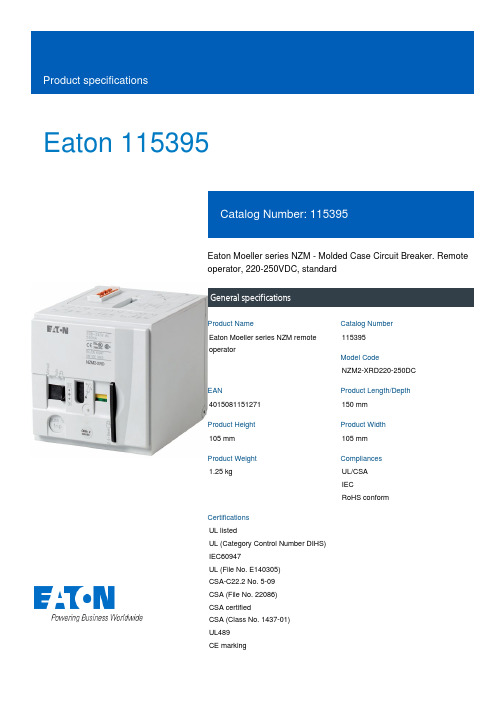
Eaton 115395Eaton Moeller series NZM - Molded Case Circuit Breaker. Remote operator, 220-250VDC, standardGeneral specificationsEaton Moeller series NZM remote operator115395NZM2-XRD220-250DC4015081151271150 mm 105 mm 105 mm 1.25 kgUL/CSA IECRoHS conformUL listedUL (Category Control Number DIHS) IEC60947UL (File No. E140305) CSA-C22.2 No. 5-09 CSA (File No. 22086) CSA certifiedCSA (Class No. 1437-01) UL489 CE markingProduct NameCatalog Number Model CodeEANProduct Length/Depth Product Height Product Width Product Weight Compliances CertificationsIs the panel builder's responsibility. The specifications for the switchgear must be observed.1.1 x UsNZM2100 ms0 VMeets the product standard's requirements.Is the panel builder's responsibility. The specifications for the switchgear must be observed..85Does not apply, since the entire switchgear needs to be evaluated.Meets the product standard's requirements.220 V450 W (24 - 30 V DC)Meets the product standard's requirements.0 VMeets the product standard's requirements.Is the panel builder's responsibility.eaton-feerum-the-whole-grain-solution-success-story-en-us.pdf eaton-digital-nzm-brochure-br013003en-en-us.pdfeaton-digital-nzm-catalog-ca013003en-en-us.pdfDA-DC-03_NZM2eaton-circuit-breaker-padlock-nzm-rotary-handle-dimensions.eps eaton-circuit-breaker-remote-operator-nzm-remote-operator-dimensions.epsM2-XRD220-250DCIL01219025ZIntroduction of the new digital circuit breaker NZMThe new digital NZM RangeDA-CS-nzm2_xrDA-CD-nzm2_xreaton-nzm-technical-information-sheet10.11 Short-circuit ratingOperating voltage - maxFrameSignal duration of remote operator at switch off - minRated control supply voltage (Us) at AC, 50 Hz - min10.4 Clearances and creepage distances10.12 Electromagnetic compatibilityVoltage tolerance - min10.2.5 Lifting10.2.3.1 Verification of thermal stability of enclosuresRated control supply voltage (Us) at DC - minPower consumption10.2.3.2 Verification of resistance of insulating materials to normal heatRated control supply voltage (Us) at AC, 50 Hz - max10.2.3.3 Resist. of insul. mat. to abnormal heat/fire by internal elect. effects10.8 Connections for external conductors Brochures Catalogues Certification reports DrawingseCAD model Installation instructions Installation videos mCAD model Technical data sheetsLifespan, mechanical20000 operationsClosing delay110 ms - 170 msVoltage rating220 - 250 V DCSwitch drive typeMotor drive10.9.2 Power-frequency electric strengthIs the panel builder's responsibility.Special featuresSliding switch for "Auto" or "Manual" Max. number auxiliary contacts: 2 standard auxiliary contacts, 1 trip-indicating auxiliary switches Cannot be combined with switch-disconnector PN... Cannot be combined with mechanical interlock Do not installM22-CK11(20/02) dual auxiliary contacts in the center auxiliary contact slot in NZM2-XRDVoltage tolerance - max1.1Rated control supply voltage (Us) at AC, 60 Hz - min0 V10.7 Internal electrical circuits and connectionsIs the panel builder's responsibility.Terminal capacity (solid/flexible conductor)0.75 mm² - 2.5 mm² with ferrule18 - 14 AWG10.10 Temperature riseThe panel builder is responsible for the temperature rise calculation. Eaton will provide heat dissipation data for the devices.Rated control supply voltage (Us) at DC - max250 V10.9.3 Impulse withstand voltageIs the panel builder's responsibility.Number of polesThree-pole/Four-poleTypeAccessory Remote operator, standard10.2.2 Corrosion resistanceMeets the product standard's requirements.10.6 Incorporation of switching devices and componentsDoes not apply, since the entire switchgear needs to be evaluated.10.2.4 Resistance to ultra-violet (UV) radiationMeets the product standard's requirements.10.2.7 InscriptionsMeets the product standard's requirements.Breaking time110 ms - 170 ms10.5 Protection against electric shockDoes not apply, since the entire switchgear needs to be evaluated.Rated control supply voltage (Us) at AC, 60 Hz - max0 VSignal duration of remote operator at switch on - min100 msUsed withNZM2(-4)N(S)2(-4)Operating voltage - min0.85 x UsNumber of operations per hour - max12010.13 Mechanical functionThe device meets the requirements, provided the information in the instruction leaflet (IL) is observed.10.2.6 Mechanical impactDoes not apply, since the entire switchgear needs to be evaluated.10.9.4 Testing of enclosures made of insulating materialIs the panel builder's responsibility.10.3 Degree of protection of assembliesDoes not apply, since the entire switchgear needs to be evaluated.Voltage typeDCEaton Corporation plc Eaton House30 Pembroke Road Dublin 4, Ireland © 2023 Eaton. All rights reserved. Eaton is a registered trademark.All other trademarks areproperty of their respectiveowners./socialmedia。

Date: 2013.07.08 - Version 3E The hoist comes supplied in two parts: a lower section (A), and a upper section (B)• Slot the upper section’s mast (C) into the upright square tubing (D) of the lower section.• Firmly tighten the wing handle (E) positioned on the right side of the upright square tubing (D).• On models equipped with a Linak actuator, the plug is already inserted in the underside of the box (1).• Insert the leg spreading plug into the socket (2). With a Linak electronic box, the plug is inserted in the socket found on the underside of the box.• On the Linak electronic box the hand control plug is already inserted in the socket (6) on the underside of the electronic box.• Check if the emergency stop button (4) is released.• Test that the hoist is functioning perfectly before using it on a patient.Max. weight capacity: falls within the stated max. weight capacity of the lift.Service / Maintenance. and detailed check of all parts on the entire lift/hoist must be carried out by an authorised service technician.Technical FeaturesHand control: The hand control is equipped with either 2 or 4 functions, which are marked with arrows: 2 functions: up/ down; 4 functions: up /down, in/out. It has an expandable spiral cord, and is magnetically attached for flexible positioning, allowing the career to be close to the patient when working with the hand control.Battery Indicator &/or Lift Counter: There is a LCD display on the battery box indicating the battery level capacity (when charging is needed), and a lift counter.Battery Alarm: An audible beep sounds when charging is needed.Fuse: On the battery box there is an automatic overload fuse, which shuts down the lift in case of overload. Then the pa-tient must be lowered by pressing the emergency down lower button using a thin pin.Emergency Stop Button: The emergency stop button can be found on the battery box anddisconnects the power supply immediately by depressing it. To release the button again, turn the knob slightly clockwise. This button is not a start/stop button, and must always be in the release mode during normal operation and when charg-ing.Emergency Down Button Manual: If the hoist for some reason malfunctions, the red emergengy-down button is located on the actuator. Lift up the down-button to release the lifting arm. The more you lift the button, the greater the lowering speed.Emergency Up/Down Button: In case of hand control malfunctions, there is an emergency electricup/down button for the lifting arm on black electronic boxes. On Linak electronic boxes there is a manual down button. Charging: Lock castors prevent damages to charger cord. Insert the charger plug into the wall socket. The red/green lamp will light up when the battery is fully charged, and the charging will automatically switch off: Green = fully charged; Red = uncharged. We recommend a fixed routine for battery charging, e.g. overnight, or having an extra battery for use while charging another.Manoeuvering: When manoeuvring the hoist with a patient, the legs must be fully splayed. By pulling (not pushing) the hoist, the patient is moved in a quieter motion, and strain on the carer is reduced to a minimum. Therefore, only push the hoist when manoeuvring it under a bed. When turning the hoist, the carer will stand by the long side, letting the hoist rotate around its own axis. With one hand, pull one way on the handle bar and with the other hand push the other way, lightly holding onto the sling, or right under the hanger bar.Never try to turn the hoist by using the handle bars, as this may result in the patient”turning”.Transport: The hoist is not designed as a mean of transport. Try to develop work routines which reduce the moving the hoist. For example, when the patient is in the hoist, and has been pulled away from the bed, it is much easier to move an object to the patient than to move the patient to the object. As a rule, move the aid that has the largest wheels and is empty.Brakes: T he castors should only be braked when parking the hoist, e.g.:a) When lifting, a non-braked hoist will automatically”move itself” into position, so that the actual lift itself is performed vertically, without moving the point of gravity.b) When lowering the patient onto the chair, the hoist can be pushed away from the patient, as the sling straps loosen.Cleaning: Clean with Micro fibre cloths only. Water based cleaning solutions can be used, but with no solvents. Wipe dry afterwards.Ergolet Taarnborgvej 12C 4220 Korsoer Denmarktel. +45 70 27 37 20e-mail:****************** Dealer Manufacturer Careline ApS Nygyde 25642 Millinge Denmark。

URL Specifications are subject to change without prior notice and any obligation on the part of the manufacturer.Ver.AContentsThank you for purchasing the SMC reduced wiring system EX250 series.Please read this instruction manual carefully and understand the contents before use so that you can operate this unit safely and correctly.Please keep this manual handy for future reference.OPERATORThis instruction manual has been written for those who have knowledge ofmachines and equipments that use reduced wiring system as well as the sufficient knowledge to assemble, operate, and maintain such devices.Before performing assembly, operation and/or maintenance, please read this manual carefully and understand the contents.To facilitate recycling, this manual is printed using biodegradable soy ink, which can easily be de-inked.This manual is printed in the "non-water system", which does not output toxic liquid waste.SAFETY ..........................................................................................................2Product Summary............................................................................................5SI UnitModel Indication Method...............................................................................6Part Names...................................................................................................6Dimensions...................................................................................................7Mounting/Installation.....................................................................................7Specifications..............................................................................................10Wiring..........................................................................................................12Display/Setting............................................................................................15Input BlockModel Indication Method.............................................................................18Part Names.................................................................................................18Dimensions.................................................................................................19Mounting/Installation...................................................................................19Specifications..............................................................................................19Wiring..........................................................................................................20Display/Setting............................................................................................22EX9 Series Output Block/Power BlockModel Indication Method.............................................................................23Part Names.................................................................................................24Dimensions.................................................................................................25Mounting/Installation...................................................................................25Specifications..............................................................................................25Wiring .........................................................................................................26Display........................................................................................................30Option............................................................................................................31Troubleshooting (33)The body of unit and this manual contain the essential information for the protection of users and others from possible injury and property damage and to ensure correct handling.Please check that you fully understand the definitions of the following messages( symbols ) before going on to read the body of this manual, and always follow the instructions.Please also read the instruction manuals etc. of related machines and equipments and understand the contents before use.Do not disassemble,modify ( including modification of printed circuit board ) or repair. Otherwise injury or failure can result.Do not operate beyond specification range.Otherwise fire, malfunction or damage to the reduced wiring system can result. Confirm the specifications before operation.Do not operate in atmosphere of flammable/explosive/corrosive gas. Otherwise fire, explosion or corrosion can result.This reduced wiring system is not explosion-proof type.For use in interlock circuit:Provide double interlock system by adding different type of protection ( such as mechanical protection ).Check that the interlock circuit is working normally.Otherwise accident caused by malfunction can result.Before performing maintenance:Turn off power supply.Stop air supply, exhaust compressed air in piping, and confirm the release to atmosphere.Otherwise injury can result.The direct current power supply to combine should be UL1310 cass 2 power supply when onformity to UL is necessary.Handling precautionsUse the following UL-recognized DC power supply to combine with.End PlateThis system realizes reduced wiring between the input and output equipment by connecting to EtherNet/IP. EtherNet/IP and the input and output equipment communicates through the SI Unit.Up to 32 Inputs can be connected to the SI Unit using Input Blocks.Up to 32 Outputs Note)from combined EX9 Output Blocks and Valve manifolds can be connected to the SI Unit.Note) The maximum output point is 24 when the Power Block is connected.Follow the instructions given below when handling your reduced wiring system.Otherwise a damage or failure to cause a malfunction can result.Operate the reduced wiring system at the specified voltage.Reserve space for maintenance.Do not remove any name plate or label.Do not drop, hit or apply an excessive shock to the unit.Follow the specified tightening torque.Do not apply any excessive force to cables by repeated bending, tensioning or placing a heavy object on the cables.Connect wires and cables correctly.Do not perform any wiring work while the power is on.Do not use the reduced wiring system on the same wiring route as the power line or high voltage line.Confirm the insulation of wiring.Perform the power supply wiring by dividing into two lines ---- one is for power supply for output and the other is for power supply for input and controlling.Take sufficient measures against noise such as noise filter when incorporating the reduced wiring system into a machine or equipment.Mount a Waterproof Cap on each unused M12 connector for input/output.Take sufficient shielding measures when operating the product in any of the following places.( 1 ) A place where noise due to static electricity etc. is generated ( 2 ) A place of high electric field strength( 3 ) A place where exposure to radioactivity is possible ( 4 ) A place near power cableDo not operate the product in a place where there is a source of surge.Use a surge absorbing element built-in type to directly drive the load that generates surge voltage such as solenoid valve.Prevent any foreign matter such as remnant of wires from getting inside the product when opening the station number switch protective cover.Install the reduced wiring system in a place free from vibration and impact.Operate the product in the specified ambient temperature range.Do not use in a place to be affected by the radiant heat from a surrounding heat source.Set the DIP switch by using a sharp-pointed watchmakers screwdriver etc.Perform the maintenance regularly.Conduct an appropriate functional inspection after completing the maintenance.Do not use chemicals such as benzin and thinner to clean the product.System configuration generalTie-rod (2 pcs.)AccessoryNote1 : For wiring method, refer to subsection "Wiring" (page 12) in this manual.Note2 : For display and setting method, refer to subsection "Display/Setting" (page 15) in this manual.BUSPWR-----64.459.86378.9Mounting/InstallationHow to assemble / disassemble units.SI Unit bodyPart NamesLayout of the Input BlockPosition the Input Block on the left side of the SI Unit.Layout of the EX9 series Output Block / Power BlockPosition the Output Block / Power Block on the right side of the SI Unit and between the SI Unit and solenoid valve or End Plate R (on the Output Block side).1) Output Block for high wattage loadThe Output Block for high wattage load cannot be used independently.Be sure to combine with the Power Block for use.2) Position of Output Block for high wattage loadThe Output Block for high wattage load cannot be mounted at the place nearer to the SI Unit than the Power Block. However, that place is acceptable if the Power Block is located between SI Unit and the Output Block for high wattage load.3) Output Block for low wattage loadThe Output Block for low wattage load cannot be mounted at the right side of the Power Block. Mount to the place nearer to the SI Unit than the Power Block. Position of End PlateBe sure to connect the End Plate (on the Input Block side) at the left end of the manifold.When the valve is not connected, be sure to connect the End Plate R (on theOutput Block side) at the right end of the manifold.Installation example Dimensions with solenoid valves unconnected [Unit: mm]* Each dimension shows the unit without solenoid valves connected and with an End PlateR (on the Output Block side) connected. Standard settings of L dimensions are with 10or less m blocks. Ask SMC sales for the setting with over 10 blocks mounted.Refer to the individual specifications for the dimensions when the solenoid valves areconnected.Wiring (power supply, communication, input/output) and piping are all in one direction.Space for wiring and piping is required in that direction.For highwattage loadPowerBlockFor highwattage loadFor high For high For highPower Power For highPowerSI Unit SI UnitFor lowwattage loadFor lowwattage loadPowerBlockFor low wattage loadSensor input areaI/O mappingInput area mappingL : Fixed to LowDiagnostics (Status input area)Output area mappingBasic specificationsConnect the Power Supply Cable to the power supply connector of SI Unit.When selecting the power supply, refer to "Handling precautions" (page 3) in this manual. Connect the Ethernet Communication Cable to the communication connector of SI Unit.Cable connectionPin layout and connection diagram of power supply connector cable for (unit : mm)Both single power supply and two power supply systems can be adopted, however, the wiring shall be made separately (for solenoid valves/output and for input and control) for either system.A. Two power suppliesSettings for display*1 : Remote control (SW1 Dip Switches 1 to 4 off)SMC's EX250 SI Unit will respond to the following Rockwell Automation BOOTP/DHCP Server commands.Enable DHCPSelecting this function will enable the EX250 SI Unit to retrieve its boot information from the BOOTP/DHCP Server. If DHCP is enabled the EX250 SI Unit will retrieve its boot information during the next power up.Disable BOOTP/DHCPSelecting this function will disable the EX250 to retrieve its boot information from the BOOTP/DHCP Server, and causes the EX250 to retain its current configuration during the next power up.*2 : DHCP Mode (SW1 Dip Switches 1 to 4 on)The IP address is acquired via DHCP Server. The IP address is not saved and lost if the power to the EX250 unit is cycled.*3 : Hardware AddressingThe IP address range is 192.168.0.1-192.168.0.14.Default settingsAt the time of factory shipment, the product is in "Remote Control Mode" and set to "Enable DHCP".Switch settingOpen the switch protective cover and set the switches with a sharp-pointed watchmakers screwdriver etc.181920212223Switch settingApplicable sensor to the Input Block can be switched to NPN/PNP.Remove the Input Block according to the "Mounting/Installation" (Page 7) in this operation manual, then set up the switch with a sharp-pointed watchmakers screw driver etc.Install the Input Block after the setting according to "Mounting/Installation" (Page 7) in this operation manual.NPN/PNP selector switchNPN PNPDisplayThe EX9 series General Purpose Output Block is the unit to operate various output (solenoid valve, relay, etc.) in combination with valve and SI Unit.There are two types ---- one type is for low wattage load (EX9-OET1) receiving power supply from SI Unit, and the other type is for high wattage load (EX9-OEP1) receiving power supply from an external source. NOTE)The type for high wattage load is used in combination with the Power Block (EX9-PE1)connected with external power supply.As the low wattage load type is powered from SI Unit, the wattage of load is limited to 1.5W NOTE). For a load up to 12W, use the Power Block and the high wattage load type.Output BlockPower BlockOutput Block Power Block Output BlockNote1 : For wiring method, refer to subsection "Wiring" (page 28) of section "EX9 Series OutputBlock/Power Block" in this manual.Note2 : For display, refer to subsection "Display" (page 30) of section "EX9 Series Output Block/Power Block" in this manual.24Pin alignment and connection drawing of the Output Cable262728293031DisplayOutput BlockPower BlockEX500-How to order010 1[m]050 5[m]S StraightEX9-How to order020 2[m]EX9-How to orderOutput CableFor details, refer to subsection "Wiring" (page 26) of section "EX9 series OutputBlock/Power Block" in this manual.EX9-How to orderPower Supply Cable (for power input connector of Power Block)For details, refer to subsection "Wiring" (page 29) of section "EX9 series Output Block/Power Block" in this manual.How to orderEthernet Communication CableFor details, refer to subsection "Wiring" (page 12) in section "SI Unit" in this manual.Power Supply CableFor details, refer to subsection "Wiring" (page 13) of section "SI Unit" in this manual.EX9-33Waterproof CapMounted on the unused ports of the Input Block, Output Block and Power Block.The proper use of this Waterproof Cap can achieve IP67 Enclosure. (The Waterproof Caps are delivered together with the Power Block as accessories.)9How to orderEnd Plate (Input Block side)7EX250-How to orderAccessoryHexagon thin socket head bolt (2 pcs.)End Plate R (Output Block side)8EX9-How to order12.56660187564.412.566607564.418EX250-EA1EX250-EA26075661812.5661812.57560EX9-EA03EX9-EA04Overall systemEtherNet/IP compatible communication34。
Catalog Numbers 700-1308-22, 700-1308-25, MMI-MML-250M-NR-SER-SYNCAC, 700-1708-22, 700-1708-25, 700-1708-25-AC•MagneMover LITE railless systems consist of modules that include motors, vehicles (pucks) with integral magnet arrays, switches, controllers, and power supplies.•MagneMover LITE motors contain integral motor controllers and position sensing.•Railless motors are compatible with the MagneMotion Precision Rail guidance and vehicle system. Alternately, cus-tomers can design their own guidance and vehicle system.•Magnet arrays used with motors are approximately 62mm by 62mm.•Up to nine vehicles in motion per meter depending upon vehicle size.•Up to ten vehicles in queue per meter standard, up to twelve vehicles in queue per meter depending upon application.•Location repeatability to ±0.5mm, station repeatability to ±0.1mm with calibration.•Wash-down capable (designed for IEC 60529, IP65).•CE Certified, UL Recognized.Physical SpecificationsEnvironmental Specifications*All dimensions are in millimeters. Contact MagneMotion for detailed drawings.Electrical SpecificationsPerformance Specifications ††Operating performance will vary based on payloads, acceleration and velocity settings, and vehicle density (refer to tables).‡Single array vehicle recommended maximum payload is 2.5kg, dual array vehicle recommended maximum payload is 5.0kg.Dimensions *:103.3W x 250.0L x 66.2HAmbient Temperature:0°C to 50°C [32°F to 122°F]Weight:1.9kg [4.2lb]Relative Humidity:85% max (relative, non-condensing)Drive Rating:36VDC ±10%, 0.4A typical, 1.2A max.Recommended Max Acceleration:2m/s 2 [0.2g]Power:5W drawn by the motor alone.Maximum additional power drawn by the motor is 15W per magnet array when thevehicle is moving at maximum accelera-tion or velocity.Recommended Max Velocity: 2.0m/s [4.5mph]Repeatability:(at recommended max payload)±0.50mm nominal ±0.10mm with calibration Recommended Max Payload: 2.5kg+ per vehicle‡Alignment Blocks(4X)14.2250 mm Railless MotorRockwell Automation SupportUse the following resources to access support information.Documentation FeedbackY our comments will help us serve your documentation needs better. If you have any suggestions on how to improve this document, complete the How Are W e Doing? form at /idc/groups/literature/documents/du/ra-du002_-en-e.pdf .Technical Support CenterKnowledgebase Articles, How-to Videos, FAQs, Chat, User Forums, and Product Notification Updates.https:///Local Technical Support Phone Numbers Locate the phone number for your country./global/support/get-support-now.page Direct Dial Codes Find the Direct Dial Code for your product. Use the code to route your call directly to a technical support engineer./global/support/direct-dial.page Literature LibraryInstallation Instructions, Manuals, Brochures, and Technical Data./global/literature-library/overview.page Product Compatibility and Download Center (PCDC)Get help determining how products interact, check features and capabilities, and find associated firmware./global/support/pcdc.pageRockwell Otomasyon Ticaret A.Ş., Kar Plaza İş Merkezi E Blok Kat:6 34752 İçerenköy, İstanbul, T el: +90 (216) 5698400Rockwell Automation maintains current product environmental information is on its website at /rockwellautomation/about-us/sustainability-ethics/product-environmental-compliance.page .Product certificates are located in the Rockwell Automation Literature Library: /global/literature-library/overview.page Allen-Bradley, Rockwell Software, and Rockwell Automation are trademarks of Rockwell Automation, Inc.Trademarks not belonging to Rockwell Automation are property of their respective companies.Copyright © 2015–2020 MagneMotion, A Rockwell Automation Company. All Rights Reserved.139 Barnum Road, Devens, MA 01434, USA +1 978-757-9100Publication MMI-TD028B-EN-P - March 2020DIR 990000683Supersedes 990000683 Rev. A。
Step 17. Enter Alarm 1 Enable/Disable Submenu Press d to display flashing DSBL / ENBL .Step 18. Enable Alarm 1 SubmenuIf flashing ENBL is displayed, press a , if DSBL is displayed,press b until ENBL is displayed, then press d to store and go to the next menu item.Step 19. Select the Deviation Control Type Submenu Press d . If flashing _DEV Deviation is displayed press a ,otherwise press b until flashing _DEV is shown. Now press d to store and go to next menu item.Step 20. Select the Latched Type SubmenuPress d . If flashing UNLT Unlatched is displayed press a ,otherwise press b until UNLT is displayed.Press d to store and advance to next menu item.Step 21. Select the Normally Open Type of Contact Closure SubmenuPress d . If flashing N.o.Normally Open is displayed,press a , otherwise press b until N.o.is displayed. Press d to store and advance to next menu item.Step 22. Select the Above Type of Active Submenu Press d . If flashing ABoV Above is displayed, press a ,otherwise press b until ABoV is displayed. Press d to store and advance to next menu item.Step 23. Enable Alarm 1 at Power On (A.P.oN )Press d . If flashing ENBL is displayed, press a , otherwise press b until ENBL is displayed. Press d to store and advance to next menu item.Step 24. Enter Alarm 1 High SubmenuPress a twice to skip ALR.L Alarm 1 Low value. ALR.L is for below & ALR.H for above.Step 25. Set the Alarm 1 High value (ALR.H )Press d . Press b or c until value to set the display to 002.0. Press d to save.Step 26. Enter the Alarm 2 MenuThe display will show ALR2the top menu for Alarm 2.Repeat steps from 17 to 25 to set for Alarm 2 the same conditions as for Alarm 1.Step 27. Skip the Loop Break Time Menu (LOOP )Press a to go to the OUT1Output 1 Menu item.Step 28. Configuration the Output 1 MenuSet Alarm 1 Disabled (Step 18) to be able to Enable Output 1.Step 29. Configuration of Display Color Selection Press a until the COLR Display Color Selection Menu appears on the Display. Configure COLR as N.CLR /GRN (green), 1.CLR / RED (red), 2.CLR /AMBR (amber). Please refer to the operator’s manual if needed.For color change on Setpoints refer to Owners Manual Section 2.MQS4007/0411SPECIFICATIONSENSOR SPECIFICATIONSRelative Humidity Accuracy/Range:±2% for 10 to 90%±3% for 5 to 10% and 90 to 95%±4% for 0 to 5% and 95 to 100%Non-linearity : ±3%Hysteresis: ±1% RH Response Time :8 sec, tau 63%Repeatability : ±0.1%Resolution : 0.1%, 12bitTemperature Accuracy/Range*:±0.5°C for 5 to 45°C (±1°F for 41 to 113°F); up to ±1.5°C for -40 to 5°C and 45 to 124°C (up to ±2.7°F for -40 to 41°F and 113 to 257°F)*NOTE:extended temp range is for Probe only, the Controller’s operating temp is 0-50°CResponse Time : 5 to 30 sec, tau 63%Repeatability : ±0.1°C Resolution : 0.1°C, 14 bit METER SPECIFICATIONS Display:4-digit, 9-segment LED, •10.2 mm (0.40")Red, green, and amber programmable colors for setpoint and temperature units.Output 1†:Relay 250 Vac @ 3 A Resistive Load,SSR, Pulse Output 2†:Relay 250 Vac @ 3 A Resistive Load,SSR, Pulse †Only with -AL Limit Alarm optionOptions:Communication RS-232 / RS-485or Excitation:24 Vdc @ 25 mAExc. not available for Low Power OptionLine Voltage/Power:90 - 240 Vac ±10%,50 - 400 Hz*, or 110 - 375 Vdc, 4 W* No CE compliance above 60 HzLow Voltage Power Option:12 - 36 Vdc or 24 Vac** ±10%, 3 W**Units can be powered safely with 24 Vac but No Certification for CE/UL are claimed.Dimensions:25.4 H x 48 W x 126.3 D mm (1.0 x 1.89 x 5")Weight:127 g (0.28 lb)Approvals:CE per EN61010-1:2001It is the policy of OMEGA to comply with all worldwide safety and EMC/EMI regulations that apply.OEMGA is constantly pursuing certification of its products to the European New Approach Directives.OMEGA will add the CE mark to every appropriate device upon certification.The information contained in this document is believed to be correct, but OMEGA Engineering,Inc.accepts no liability for any errors it contains, and reserves the right to alter specifications without notice.TRADEMARK NOTICE:®,®,, andare Trademarks ofOMEGA ENGINEERING, INC.®This Quick Start Reference provides informationon setting up your instrument for basic operation.The latest complete Communication and OperationalManual as well as free Software and ActiveX Controlsare available at /specs/iseriesor on the CD-ROM enclosed with your shipment. SAFETY CONSIDERATIONThe instrument is a panel mount device protected in accordance with EN61010-1:2001. Remember that the unit has no power-on switch. Building installation should include a switch or circuit-breaker that must be compliant to IEC 947-1 and 947-3.SAFETY:•Do not exceed voltage rating on the label located onthe top of the instrument housing.•Always disconnect power before changing signal andpower connections.•Do not use this instrument on a work bench withoutits case for safety reasons.•Do not operate this instrument in flammable orexplosive atmospheres.•Do not expose this instrument to rain or moisture. EMC:•Whenever EMC is an issue, always use shielded cables.•Never run signal and power wires in the same conduit.•Use signal wire connections with twisted-pair cables.•Install Ferrite Bead(s) on signal wire close to theinstrument if EMC problems persist.MOUNTINGPanel Mounting Instruction:ing the dimensions from the panel cutout diagramshown above, cut an opening in the panel.2.Insert the unit into the opening from the front of thepanel, so the gasket seals between the bezel and thefront of the panel.3.Slide the retainer over the rear of the case and tightenagainst the backside of the mounting panel.。
<EX260-SPN1/-SPN2/-SPN3/-SPN4>InstallationConfigurationIn order to configure the SI unit for the PROFINET network, the appropriate device master file (GSD file) for the SI unit will be required.Technical documentation giving detailed configuration information and the GSD file can be found on the SMCwebsite (URL ).General instructions on installation and maintenanceConnect valve manifold to the SI unit.Connectable valve manifolds are the same as for EX250 series SI unit.Refer to the EX250 series valve manifold section in the valve catalogue for valvemanifold dimensions.Power supply connector layoutGround terminalConnect the ground terminal to ground.Resistance to ground should be 100 ohms or less.SettingReplacement of the SI unit•Remove the M3 hexagon screws from the SI unit and release the SI unit from the valve manifold.•Replace the SI unit.•Tighten the screws with the specified tightening torque. (0.6 Nm)Precautions for maintenance •Be sure to switch off the power.•Check there is no foreign matter inside the SI unit.•Check there is no damage and no foreign matter being stuck to the gasket.•Be sure to tighten the screw with the specified torque.If the SI unit is not assembled properly, inside PCBs may be damaged or liquid and/or dust may enter into the unit.Connecting cablesSelect the appropriate cables to mate with the connectors mounted on the SI unit.TroubleshootingTechnical documentation giving detailed troubleshooting information can be found on the SMC website (URL ).SpecificationsConnected load: 24VDC Solenoid valve with surge voltage suppressor of 1.0 W or less (manufactured by SMC)Current consumption of power supply for SI unit operation: 0.1 A max.Ambient temperature for operation: -10 to 50 C Ambient temperature for storage: -20 to 60 CTechnical documentation giving detailed specification information can be found on the SMC website (URL ).Outline DimensionsTechnical documentation giving detailed outline dimensions information can be found on the SMC website (URL ).AccessoriesTechnical documentation giving detailed accessories information can be found on the SMC website (URL ).Assembly and disassembly of the SI unitNOTEWhen conformity to UL is necessary the SI unit must be used with a UL1310Class 2 power supply.Safety InstructionsSafety InstructionsThese safety instructions are intended to prevent hazardous situations and/or equipment damage.These instructions indicate the level of potential hazard with the labels of"Caution", "Warning" or "Danger". They are all important notes for safety and must be followed in addition to International standards (ISO/IEC) and other safety regulations.Operator2 pcs. M3 x 30 screw for connection to the valve manifold Seal cap1 pc. seal cap for unused fieldbus interface connector (BUS OUT)Hexagon socket head cap screw PWR: M12 5-pin plug A-coded (SPEEDCON)GSD fileOutput number assignmentOutput numbering starts at zero and refers to the solenoid position on the manifold.Diagnostic informationWhen the load voltage for the valve is 19 V or less, the SI unit will send an error message to the master as diagnostic information, and the SF LED will turn ON.Technical documentation giving detailed diagnostics information can be found on the SMC website (URL ).Note: Specifications are subject to change without prior notice and any obligation on the part of the manufacturer.© 2011-2016 SMC Corporation All Rights Reserved Akihabara UDX 15F, 4-14-1, Sotokanda, Chiyoda-ku, Tokyo 101-0021, JAPAN Phone: +81 3-5207-8249 Fax: +81 3-5298-5362URL Fieldbus interface connector layoutEX ※※-OMO0031-BThe M12 connector cable has two types, SPEEDCON compatible andnon-compatible. If both plug and socket sides have connectors for SPEEDCON, the cable can be inserted and connected by turning it a 1/2 of a rotation, leading to reduction in work hour.A non-compatible connector can be connected to a compatible connector as well as an M12.The M12 connector cable has two types, SPEEDCON compatible andnon-compatible. If both plug and socket sides have connectors for SPEEDCON, the cable can be inserted and connected by turning it a 1/2 of a rotation, leading to reduction in work hour.A non-compatible connector can be connected to a compatible connector as well as an M12.Before UseFieldbus deviceEX260 Series for PROFINETThank you for purchasing an SMC EX260 Series Fieldbus device (Hereinafter referred to as "SI unit" ).Please read this manual carefully before operating the product and make sure you understand its capabilities and limitations. Please keep this manual handy for future reference.。
Series 121, DN 160 - 250 (I.D. 6" - 10")VAT Vakuumventile AG, CH-9469 Haag, SwitzerlandTel +41 81 771 61 61 Fax +41 81 771 48 30 CH@ 218567EF2010-10-041/18Vacuum gate valvewith pneumatic actuatorThis manual is valid for the valve ordering number(s):12144- . A14/24/34/44 12146- . A14/24/34/44 12148- . A14/24/34/44The fabrication number is indicated on each product as per the label below (or similar):Explanation of symbols:Read declaration carefully before you start any other action!Keep body parts and objects away from the valve opening!Attention!Hot surfaces; do not touch!Product is in conformity with EC guidelines, if applicable!Loaded springs and/or air cushions are potential hazards!Disconnect electrical power and compressed air lines. Do not touch parts under voltage!Wear gloves!Series 121, DN 160 - 250 (I.D. 6" - 10")VAT Vakuumventile AG, CH-9469 Haag, SwitzerlandTel +41 81 771 61 61 Fax +41 81 771 48 30 CH@ 218567EF2010-10-042/18Imprint:VAT Vakuumventile AG, CH-9469 Haag, Switzerland ManufacturerWebsite Phone+41 81 771 61 61Fax+41 81 771 48 30EmailCH@Publisher VAT Vakuumventile AG, CH-9469 Haag, SwitzerlandEditor VAT Vakuumventile AG, CH-9469 Haag, SwitzerlandPrint VAT Vakuumventile AG, CH-9469 Haag, SwitzerlandCopyright © VAT Vakuumventile AG 2008No part of these Instructions may be reproduced in any way (photocopies, microfilms or anyother reproduction processes) nor may it be manipulated with electronic systems, duplicated ordistributed without written permission from VAT. Offenders are liable to pay damages.The original VAT firmware and updated state of the art versions of the VAT firmware areintended for use with VAT products. The VAT firmware contains a limited, time unlimited userlicense. The VAT firmware may not be used for purposes other than those intended nor is itpermitted to make copies of the VAT firmware. In particular, it is strictly forbidden to givecopies of the VAT firmware to other people.The use of trade names, brand names, trademarks, etc. in these Instructions does not entitlethird parties to consider these names to be unprotected and to use them freely. This is inaccordance with the meaning of the laws and acts covering brand names and trademarks.Series 121, DN 160 - 250 (I.D. 6" - 10")VAT Vakuumventile AG, CH-9469 Haag, SwitzerlandTel +41 81 771 61 61 Fax +41 81 771 48 30 CH@ 218567EF2010-10-043/18Contents:1Use of product (4)1.1Technical data (4)2Installation (4)2.1Unpacking (4)2.2Installation into the system (5)2.2.1Tightening torque for flange screws (5)2.2.2Admissible forces (5)2.3Connections (6)2.3.1Compressed air connection (6)2.3.2Electrical connection (7)3Operation (8)3.1Normal operation (8)3.2Operation under increased temperature (8)3.3Behavior in case of compressed air pressure drop (8)3.4Behavior in case of power failure (8)3.5Emergency operation at power failure (8)4Trouble shooting (9)5Maintenance & repairs (9)5.1Cleaning or replacement of gate seal and/or bonnet seal (10)5.2Cleaning or replacement of locking balls (12)5.3Cleaning or replacing of shaft feedthrough seals (13)6Drawing (16)7Spare parts (17)8Warranty (18)Series 121, DN 160 - 250 (I.D. 6" - 10")VAT Vakuumventile AG, CH-9469 Haag, SwitzerlandTel +41 81 771 61 61 Fax +41 81 771 48 30 CH@ 218567EF2010-10-044/181 Use of productUse product for clean and dry indoor vacuum applications under the conditions indicated in chapter «Technical data» only! Other applications are only allowed with the written permission of VAT.1.1 Technical dataPressure range DN 160 – 200 : 1 x 10⁻⁷ mbar to 1.6 bar (abs)DN 250 : 1 x 10⁻⁷ mbar to 1.2 bar (abs)Differential pressure on the gate DN 160 – 200 :≤ 1.6 bar in either directionDN 250 : ≤ 1.2 bar in either directionDifferential pressure at opening ≤ 30 mbarAdmissible temperature: Valve body ≤ 120°CActuator≤ 80°CPositionindicator≤ 80°CSolenoid≤ 50°CPosition indicator: Contact rating 5 A / 250 V AC, 3 A / 50 V DCSolenoid see tag on solenoidFurther data according to VAT catalogue «Vacuum Valves 2004».2 Installation2.1 UnpackingBefore unpacking the valve, make sure that the packaging is in impeccable condition and the valve has not suffered damage.Note!The plastic packing material and/or protective covers may only be removed immediately before the valve is mounted into the system. Unprotected sealing surfaces must be treated with care and kept clean.Series 121, DN 160 - 250 (I.D. 6" - 10")VAT Vakuumventile AG, CH-9469 Haag, SwitzerlandTel +41 81 771 61 61 Fax +41 81 771 48 30 CH@ 218567EF2010-10-045/182.2 Installation into the systemThe valve seat side is indicated by the symbol "∇" on the connection flange.2.2.1 Tightening torque for flange screwsThe screws of the flanges have to be tightened uniformly in crosswise order. The tightening torques indicated in the following table have to be observed.DN Tightening torque «Nm» lbf . ftmm inch ISO JIS ASA-LP ISO JIS ASA-LP 160 6 8 - 10 10 - 12 10 - 12 6 - 7.5 7.5 - 9 7.5 - 9 200 8 8 - 10 16 - 18 40 - 60 6 - 7.5 12 - 13 30 - 44 250108 - 1016 - 18-6 - 7.512 - 13-Higher tightening torques may deform the valve body. This can lead to improper function of the valve or to a leaky valve gate.2.2.2 Admissible forcesForces from evacuating the system and from the weight of other components can lead to deformation of the valve body and to malfunction of the valve. The stress has to be relieved by suitable means, e.g. bellows sections. The following forces are admissible:DN (nom. I.D.) Axial tensile or compressive force «FA» Bending moment «M» Maximum admissibletorsional moment of body«TM» mm inch Nlbf Nm lbf. ft Nmlbf . ft160 6 3000 674 150 110 10’000 7’370 200 8 3000 674 150 110 12’000 8’850 250 10 3500 787 200 148 12’000 8’850If a combination of forces («FA», «M» and «TM» ) occurs, the values mentioned above are invalid.Please contact VAT for more information.Series 121, DN 160 - 250 (I.D. 6" - 10")VAT Vakuumventile AG, CH-9469 Haag, SwitzerlandTel +41 81 771 61 61 Fax +41 81 771 48 30 CH@ 218567EF2010-10-046/182.3 Connections2.3.1 Compressed air connectionConnect compressed air only if- valve has been installed into the vacuum system- moving parts cannot be touchedWith solenoid: Connect compressed air to connection IN (internal thread R 1/8“, 1/8“ NPT for USA) Without solenoid: Connect compressed air to connection OPEN and CLOSE (internal thread M5) Solenoid delivered separately(not attached to valve):Compressed air connection atpneumatic cylinder: internal thread M5Compressed air connected to <A>:valve opensCompressed air connected to <B>:valve closesCompressed air pressure (min. - max. overpressure): 4 - 7 bar / 55 - 100 psigUse only clean, dry or slightly oiled air!Series 121, DN 160 - 250 (I.D. 6" - 10")VAT Vakuumventile AG, CH-9469 Haag, SwitzerlandTel +41 81 771 61 61 Fax +41 81 771 48 30 CH@ 218567EF2010-10-047/182.3.2 Electrical connectionDo not touch any electrically charged parts!Connect electrical power only if- valve has been installed into the vacuum system- moving parts cannot be touchedVerify that mains voltage matches voltage stated on the solenoid! Sockets for position indicator and solenoid are supplied with the valve.Wire solenoid and position indicator according to the following diagrams:Series 121, DN 160 - 250 (I.D. 6" - 10")VAT Vakuumventile AG, CH-9469 Haag, SwitzerlandTel +41 81 771 61 61 Fax +41 81 771 48 30 CH@ 218567EF2010-10-048/183 Operation3.1 Normal operationValve is opened and closed by means of compressed air.3.2 Operation under increased temperatureSee «1.1 Technical data»The maximum temperatures indicated in the technical data are only valid as long as the valve is in one of the end positions. Cycling the valve at these temperatures may reduce the cycle life of the mechanism.3.3 Behavior in case of compressed air pressure dropValve closed: valve remains closedValve open: valve position is undefined3.4 Behavior in case of power failureStandard solenoid: valve closesSolenoid for impulse actuation (option): valve position does not change, but a started movement will be completed 3.5 Emergency operation at power failureIn case of a power failure, the valve can be actuated manually if compressed air is available.Series 121, DN 160 - 250 (I.D. 6" - 10")VAT Vakuumventile AG, CH-9469 Haag, SwitzerlandTel +41 81 771 61 61 Fax +41 81 771 48 30 CH@ 218567EF2010-10-049/184 Trouble shootingFailure Check Action Valve does not close/open Power available? Connect correct voltageCompressed air available? Connect correct air pressure Solenoid defective? Replace solenoidLeak at gate Valve seat and gate seal clean?Clean valve seat and gate seal, or replace gate sealCompressed air available? Connect correct air pressure Leak at bodyFlanges leaktight? Tighten flange screws correctly Screws at upper part of body tightened? Tighten bonnet screws correctlyReplace bonnet sealIf you need any further information, please contact one of our service centers. You can find the addresses on our website: http://www.vat.ch5 Maintenance & repairsUnder clean operating conditions, the valve does not require any maintenance during the specified cycle life. Contamination from the process may influence the function and requires more frequent maintenance.Before carrying out any maintenance or repairs, please contact VAT. It has to be individually decided whether the maintenance/repair can be performed by the customer or has to be carried out by VAT. The fabrication number on the valve has always to be specified.All supplies (e. g. compressed air, electrical power) must be disconnected for removal/installation of the valve from/into the system and for maintenance work. Even with disconnected supply, loaded springs and/or air cushions in cylinders can be potential hazards.Keep fingers and objects away from the valve opening!Products returned to VAT must be free of harmful substances such as e.g. toxical, caustic or microbiological ones. If products are radioactively contaminated, fill in the VAT form «Contamination and Radiation Report» and send it with the product. The form is available at VAT. The maximum values indicated in the form must not be exceeded.Series 121, DN 160 - 250 (I.D. 6" - 10")VAT Vakuumventile AG, CH-9469 Haag, SwitzerlandTel +41 81 771 61 61 Fax +41 81 771 48 30 CH@ 218567EF2010-10-0410/185.1 Cleaning or replacement of gate seal and/or bonnet sealThe figures in brackets refer to the drawing on page 16The lower part of the body (flange part) need not be removed from the system for cleaning/replacing the gate seal and/or bonnet seal!a) Separation of upper part of body (11) / actuator assembly from lower part of body (10):1. Vent vacuum chambers on either side of valve2. Open valve by means of compressed air3. Switch off compressed air and power supply4. Disconnect compressed air and power lines from valve5. Loosen and swing out both screws (12)Attention:Make sure to maintain upper part of body (11) / actuator assembly in its positionwhile swinging out the screws!6. Withdraw upper part of body (11) / actuator assembly carefully from lower part of body (10) and put it on a cleanplace (seat side symbol «∇» on top)b) Cleaning or replacement of gate seal and bonnet seal:7. Apply compressed air (air pressure approx. 1 bar) and move mechanismslowly out of upper part of body (11)Attention:Provide sufficient free space in order to preventthe mechanism from touching any objects!← free space8. Disconnect compressed air from valve9. Clean (A) or replace (B) gate seal (1):(A) 1. Leave gate seal in groove and clean it by using a lint-free clothand alcohol2. Slightly lubricate seal with VAT vacuum grease[see «Spare parts»](B) 1. Pull gate seal out of groove by means of a scribing toolAttention: Be careful not to damage the bottom of the groove!2. Clean seal groove by using a lint-free cloth and alcohol3. Put new gate seal on seal groove and press it into groove uniformlyand crosswiseremoval of gate seal installation of gate sealSeries 121, DN 160 - 250 (I.D. 6" - 10")VAT Vakuumventile AG, CH-9469 Haag, SwitzerlandTel +41 81 771 61 61 Fax +41 81 771 48 30 CH@ 218567EF2010-10-0411/1810. Clean (A) or replace (B) bonnet seal (2):(A) 1. Leave bonnet seal in groove and clean it by using a lint-free cloth and alcohol2. Slightly lubricate seal with VAT vacuum grease [see «Spare parts»] (B) 1. Pull bonnet seal out of groove by means of a scribing toolAttention: Be careful not to damage the bottom of the groove! 2. Clean seal groove by using a lint-free cloth and alcohol3. Put new bonnet seal on seal groove and press it into groove on one short side4. Distribute seal uniformly over long sides to opposite short side and press it fully into groove11. Clean sealing surface of upper part of body (11) by using a lint-free cloth and alcohol12. Clean sealing surface of valve seat on lower part of body (10) by using a lint-free cloth and alcohol c)Mounting of upper part of body (11) / actuator assembly on lower part of body (10):13. Make sure to have gate (16) on seat side «∇»:Symbol «∇» on upper part of body (11)Note: Mechanism with actuator shaft (13) is stifflyrotatable by 360°!gate (16) (without bore holes) gate seal (1) seat side symbol 14. Align mechanism with opening of upper part of body (11)correctwrong15. Apply compressed air (air pressure approx. 1 bar) and move mechanism slowly into upper part of body (11)Attention:Make sure to keep the space between body opening and mechanism free of any objects or body parts!16. Disconnect compressed air from valve17. Set upper part of body (11) / actuator assembly carefully on lower part of body (10)Attention: The tips of the triangles «∇» of both body parts must face each other!∇ on both body parts18. Swing back both screws (12) and tighten them alternatelyTightening torque: DN 160 - 200: 14 Nm / 10.5 lbf . ft DN 250: 20 Nm / 15.0 lbf . ft 19. Connect electrical power and compressed air 20. Perform function and leak testSeries 121, DN 160 - 250 (I.D. 6" - 10")VAT Vakuumventile AG, CH-9469 Haag, SwitzerlandTel +41 81 771 61 61 Fax +41 81 771 48 30 CH@ 218567EF2010-10-0412/185.2 Cleaning or replacement of locking ballsThe figures in brackets refer to the drawing on page 16The lower part of the body (flange part) need not be removed from the system for cleaning/replacing the locking balls! When the locking balls are cleaned/replaced, we recommend to clean the gate seal and bonnet seal as well(see relevant chapter).a) Separation of upper part of body (11) / actuator assembly from lower part of body (10):1. Carry out steps 1 - 6 of chapter «Cleaning or replacement of gate seal and/or bonnet seal»,however with seat side «∇» down!b) Cleaning or replacement of locking balls:2. Apply compressed air (air pressure approx. 1 bar) and move mechanismslowly out of upper part of body (11)Attention:Provide sufficient free space in order to prevent themechanism from touching any objects!← free space3. Disconnect compressed air from valve4. Remove lock nut (14) with disk (15)5. Withdraw mechanism from actuator shaft (13) and put it on a clean place6. Remove screws (19)7. Lift off counter plate (17) carefully and put it on a clean place8. Remove all visible balls (3) from ball guidance (18)9. Lift off ball guidance (18) carefully and put it on a clean placeAttention: Balls can get caught in the lower ball sockets of the ball guidance (18)!10. Remove all balls (3) from ball tracks in gate (16)11. C lean (A) or replace (B) balls (3):(A) 1. Clean ball tracks in gate (16) and counter plate (17) by using a lint-free cloth,and check their condition with regard to wear2. Clean balls and ball sockets in ball guidance (18) by using a lint-free cloth and alcohol3. Lubricate balls with VAT vacuum grease [see «Spare parts»]4. Insert balls into ball tracks in gate (16)(B) 1. Clean ball tracks in gate (16) and counter plate (17) by using a lint-free cloth and alcohol ,and check their condition with regard to wear2. Clean ball sockets in ball guidance (18) by using a lint-free cloth and alcohol3. Insert new, lubricated balls [see «Spare parts»] into ball tracks in gate (16)(A + B) 1. Put ball guidance (18) carefully on gate (16) so that balls (3) get into ball socketsAttention: Regard correct position!2. Insert remaining balls into ball sockets in ball guidance (18)Series 121, DN 160 - 250 (I.D. 6" - 10")VAT Vakuumventile AG, CH-9469 Haag, SwitzerlandTel +41 81 771 61 61 Fax +41 81 771 48 30 CH@ 218567EF2010-10-0413/1812. Put counter plate (17) on ball guidance13. Insert and tighten screws (19)Attention:The internal screws first, then the outside screws. Tightening torque: 9 Nm!14. Move mechanism on actuator shaft (13) to its stopAttention:Spanner width of ball guidance (18) and shaft (13) must match!Mechanism must not rotate against the shaft!15. Mount lock nut (14) with disk (15)16. Clean sealing surface of upper part of body (11) by using a lint-free cloth and alcohol17. Clean sealing surface of valve seat on lower part of body (10) by using a lint-free cloth and alcoholc) Mounting of upper part of body (11) / actuator assembly on lower part of body (10):18. Carry out steps 13 - 20 of chapter «Cleaning or replacement of gate seal and/or bonnet seal»Valve is ready for operation5.3 Cleaning or replacing of shaft feedthrough sealsThe figures in brackets refer to the drawing on page 16The lower part of the body (flange part) need not be removed from the system for cleaning/replacing the shaft feedthrough seals! When the shaft feedthrough seals are cleaned/replaced, we recommend to clean the gate seal and bonnet seal as well (see relevant chapter).a) Separation of upper part of body (11) / actuator assembly from lower part of body (10):1. Carry out steps 1 - 6 of chapter «Cleaning or replacement of gate seal and/or bonnet seal»,however with seat side «∇» down!b) Cleaning or replacement of shaft feedthrough seals:2. Apply compressed air (air pressure approx. 1 bar) and move mechanismslowly out of upper part of body (11)Attention:Provide sufficient free space in order to prevent themechanism from touching any objects!← free space3. Disconnect compressed air from valve4. Remove lock nut (14) with disk (15)5. Withdraw mechanism from actuator shaft (13) and put it on a clean place6. Apply compressed air (air pressure approx. 1 bar) and move actuator shaft (13) slowly into upper part of body (11)7. Disconnect compressed air from valve8. Put upper part of body (11) / actuator assembly in upright position (actuator on top)9. Take a note in which position the actuator is mounted with regard to the seat side [see symbol «∇» on upper part ofbody (11)], so that the actuator can be mounted in the same position after completion of the maintenance workSeries 121, DN 160 - 250 (I.D. 6" - 10")VAT Vakuumventile AG, CH-9469 Haag, SwitzerlandTel +41 81 771 61 61 Fax +41 81 771 48 30 CH@ 218567EF2010-10-0414/1810. Remove 4 screws (20)11. Withdraw actuator from upper part of body (11) and put it on a clean place 12. Remove both seals (21) and spacer (22) carefully from upper part of body (11)Attention: Be careful not to damage the sealing surface!13. Clean feedthrough opening in upper part of body (11) and spacer (22) by using a lint-free cloth and alcohol 14. Clean (A) or replace (B) seals of shaft feedthrough (21); see drawing below(A)1. Clean seals by using a lint-free cloth and alcohol2. Lubricate first seal extensively with VAT vacuum grease [see «Spare parts»] and insert it in feedthroughopening in upper part of body (11) 3. Insert spacer (22)4. Lubricate second seal extensively with VAT vacuum grease [see «Spare parts»] and insert it infeedthrough opening in upper part of body (11)(B)1. Lubricate first seal extensively with VAT vacuum grease [see «Spare parts»] and insert it in feedthroughopening in upper part of body (11) 2. Insert spacer (22)3. Lubricate second seal extensively with VAT vacuum grease [see «Spare parts»] and insert it infeedthrough opening in upper part of body (11)(A + B) 1.Lubricate space between both seals extensively with VAT vacuum grease [see «Spare parts»]1121222111 upper part of body21 first and second shaft feedthrough seal22 spacer =space between both seals → area to be lubricated15. Clean actuator shaft (13):1. Apply compressed air and move out actuator shaft slowly in its full length(air pressure approx. 1 bar) 2. Clean actuator shaft by using a lint-free cloth and alcohol3. Lubricate running surface of actuator shaft slightly with VAT vacuum grease [see «Spare parts»]4. Move back actuator shaft slowly with compressed air (air pressure approx. 1 bar)5. Remove excessive grease from shaft6. Disconnect compressed air from actuator16. Put actuator on upper part of body (11)Attention: Actuator must be mounted in the same position as it was before disassembly! 17. Mount and tighten 4 screws (20)Tightening torque: DN 160: 6 Nm / 4.5 lbf . ft DN 200 - 250: 14 Nm / 10.5 lbf . ftSeries 121, DN 160 - 250 (I.D. 6" - 10")VAT Vakuumventile AG, CH-9469 Haag, SwitzerlandTel +41 81 771 61 61 Fax +41 81 771 48 30 CH@ 218567EF2010-10-0415/1818. Apply compressed air (air pressure approx. 1 bar) and move actuator shaft slowly out of upper part of body (11) 19. Disconnect compressed air from actuator 20. Remove excessive grease from shaft21.Lubricate end piece of shaft without thread slightly with VAT vacuum grease [see «Spare parts»]area to be lubricated22. Move mechanism on actuator shaft (13) to its stopAttention: Spanner width of ball guidance (18) and shaft (13) must match! Mechanism must not rotate against the shaft! 23. Mount lock nut (14) with disk (15)24. Clean sealing surface of upper part of body (11) by using a lint-free cloth and alcohol25. Clean sealing surface of valve seat on lower part of body (10) by using a lint-free cloth and alcohol c)Mounting of upper part of body (11) / actuator assembly on lower part of body (10):26. Carry out steps 13 - 20 of chapter «Cleaning or replacement of gate seal and/or bonnet seal»Valve is ready for operationSeries 121, DN 160 - 250 (I.D. 6" - 10")VAT Vakuumventile AG, CH-9469 Haag, SwitzerlandTel +41 81 771 61 61 Fax +41 81 771 48 30 CH@ 218567EF2010-10-0416/186 DrawingItem Designation Item Designation Item Designation1 gate seal 13 actuator shaft 19 countersunk-head screws2 bonnet seal 14 lock nut 20 cylinder head screws3 lockingballs 15 disk 21 feedthroughseals10 lower part of body 16 gate 22 spacer11 upper part of body 17 counter plate12 swing screws 18 ball guidanceSeries 121, DN 160 - 250 (I.D. 6" - 10")VAT Vakuumventile AG, CH-9469 Haag, SwitzerlandTel +41 81 771 61 61 Fax +41 81 771 48 30 CH@ 218567EF2010-10-0417/187 Spare partsPlease specify the fabrication number of the valve (see yellow label on valve) when ordering spare parts. This isto ensure that the appropriate spare parts are supplied.The item numbers refer to the drawing belowItemDesignation Ordering No. DN 160 200 250Seal kit 1) 216860 216859 2168571 Gate seal N-5100-258 N-5100-266 N-5100-3782 Bonnet seal N-5100-255 N-5100-264 N-5100-3763 Spare parts kit «balls lubricated» 216865 216864 216862 4 Position indicator 78855-R1 78855-R1 78855-R15 Standard solenoid with coil 2) 94800-R1 94800-R1 94800-R16 Solenoid for impulse actuation with coils 2) 94801-R1 94801-R1 94801-R1VAT vacuum grease (10g) N-6951-011 N-6951-011 N-6951-0111)Seal kit includes:gate seal, bonnet seal, shaft feedthrough sealsIn most cases it is sufficient to replace the gate seal and bonnet seal only. 2)Specify voltage!VAT Vakuumventile AG would be pleased to carry out the maintenance work for you. Please contact the VAT representative responsible for your country. You will find the addresses on our website .Please specify the fabrication number of the valve whenever you place an order for spare parts. Thefabrication number is indicated on a yellow label attached to the actuator of the valve (see product identification label on page 1).Attention: Use lubricatedspare parts only!Series 121, DN 160 - 250 (I.D. 6" - 10")VAT Vakuumventile AG, CH-9469 Haag, SwitzerlandTel +41 81 771 61 61 Fax +41 81 771 48 30 CH@ 218567EF2010-10-0418/188 WarrantyEach product sold by VAT Vakuumventile AG (VAT) is warranted to be free from the manufacturing defects that adversely affect the normal functioning thereof during the warranty period stated in VAT's «Terms of Sale» immediately following delivery thereof by VAT, provided that the same is properly operated under conditions of normal use and that regular, periodic maintenance and service is performed or replacements made, in accordance with the instructions provided by VAT. The foregoing warranty shall not apply to any product or component that has been repaired or altered by anyone other than an authorized VAT representative or that has been subject to improper installation or abuse, misuse, negligence or accident. VAT shall not be liable for any damage, loss, or expense, whether consequential, special, incidental, direct or otherwise, caused by, arising out of or connected with the manufacture, delivery (including any delay in or failure to deliver), packaging, storage or use of any product sold or delivered by VAT shall fail to conform to the foregoing warranty or to the description thereof contained herein, the purchaser thereof, as its exclusive remedy, shall upon prompt notice to VAT of any such defect or failure and upon the return of the product, part or component in question to VAT at its factory, with transportation charges prepaid, and upon VAT's inspection confirming the existence of any defect inconsistent with said warranty or any such failure, be entitled to have such defect or failure cured at VAT's factory and at no charge therefor, by replacement or repair of said product, as VAT may elect. VAT MAKES NO WARRANTY OR REPRESENTATION OF ANY KIND, EXPRESS OR IMPLIED, (INCLUDING NO WARRANTY OR MERCHANTABILITY), EXCEPT FOR THE FOREGOING WARRANTY AND THE WARRANTY THAT EACH PRODUCT SHALL CONFORM TO THE DESCRIPTION THEREOF CONTAINED HEREIN, and no warranty shall be implied by law.Furthermore, the «Terms of sale» at the back of the price list are applicable.。
DuPont Packaging&Industrial Polymers250Elvax® resins Product Data SheetProduct Description DuPont™ Elvax® 250 is an ethylene-vinyl acetate copolymer resin for use inindustrial applications.Material Status Commercial: ActiveAvailability GloballyComposition28% By Weight Vinyl AcetateThermal Stabilizer: BHT antioxidantApplications Elvax® resins can be used in a variety of applications involving molding,compounding, extrusion, adhesives, sealants, and wax blends. For additionalinformation and properties associated with specific applications, please refer to theGrade Selector Guides found on the Elvax® website for industial applications./industrial-polymers/elvax/index.html.Physical Nominal Values Test Method(s) Density ()0.921 g/cm³ASTM D792ISO 1183 Melt Index (190°C/2.16kg)25 g/10 min ASTM D1238ISO 1133 Thermal Nominal Values Test Method(s) Melting Point (DSC)70°C (158°F)ASTM D3418ISO 3146 Vicat Softening Point ()42°C (108°F)ASTM D1525ISO 306GeneralMaximum Processing Temperature230°C (446°F)General Processing Information Elvax® resins can be processed by conventional thermoplastic processingtechniques, including injection molding, structural foam molding, sheet and shapeextrusion, blow molding and wire coating. They can also be processed usingconventional rubber processing techniques such as Banbury, two-roll milling andcompression molding.Elvax can be used in conventional extrusion equipment designed to processpolyethylene resins. However, corrosion-protected barrels, screws, adapters, anddies are recommended, since, at sustained melt temperatures above 446°F(230°C), ethylene vinyl acetate (EVA) resins may thermally degrade and releasecorrosive by-products.FDA Status Information ELVAX® 250 EVA Resin complies with Food and Drug Administration Regulation21 CFR 177.1350(a)(1) - - Ethylene-vinyl acetate copolymers, subject to thelimitations and requirements therein. This Regulation describes polymers that maybe used in contact with food, subject to the finished food-contact article meeting theextractive limitations under the intended conditions of use, as shown in paragraph(b)(1) of the Regulation.Safety&Handling A Product Safety Bulletin, Material Safety Data Sheet, and more detailedinformation on compounding and processing Elvax® resins for specific applicationsare available from your DuPont Packaging and Industrial Polymers representative.Read and Understand the Material Safety Data Sheet(MSDSMSDS))before using this productRegional CentresDuPont operates in more than 70 countries. For help finding a local representative, please contact one of the following regional customer contact centers:Americas Asia Pacific Europe / Middle East / AfricaDuPont Company, BMP26-2363 Lancaster Pike & Route 141 Wilmington, DE 19805 U.S.A. Telephone +1 302-774-1161 Toll-free (USA) 800-628-6208 Fax +1 302-999-4399DuPont China Holding Co., Ltd.Shanghai Branch399 Keyuan Road, Bldg. 11Zhangjiang Hi-Tech ParkPudong New District, ShanghaiP.R. China (Postcode: 201203)Telephone +86 21 3862 2888Fax +86-21-3862-2889DuPont de Nemours Int’1. S.A.2,Chemin du Pavillon Box 50CH-1218 Le Grand SaconnexGeneva, SwitzerlandTelephone +41 22 717 51 11Fax +41 22 717 55 00DuPont do Brasil, S.A.Alameda Itapecuru, 50606454-080 Barueri, SP BrasilTelephone +55 11 4166 8122Fax +55 11 4166 8720The data listed here fall within the normal range of properties, but they should not be used to establish specification limits nor used alone as the basis of design. The DuPont Company assumes no obligations or liability for any advice furnished or for any results obtained with respect to this information. All such advice is given and accepted at the buyer's risk. The disclosure of information herein is not a licence to operate under, or a recommendation to infringe, any patent of DuPont or others. Since DuPont cannot anticipate all variations in actual end-use conditions, DuPont makes no warranties and assumes no liability in connection with any use of this information.CAUTION: Do not use DuPont materials in medical applications involving implantations in the human body or contact with internal body fluids or tissues unless the material has been provided from DuPont under a written contract that is consistent with DuPont policy regarding medicalk applications and expressly acknowledges the contemplated use. For further information, please contact your DuPont representative. You may also request a copy of DuPont POLICY Regarding Medical Applications H-50103-3 and DuPont CAUTION Regarding Medical Applications H-50102-3.Copyright © 2009 DuPont. The DuPont Oval Logo, DuPont™, The miracles of science™, and trademarks designated with "®" are registered trademarks or trademarks of E.I. du Pont de Nemours and Company or its affiliates. All rights reserved.This data sheet is effective as of 01/12/2007 06:53:37 PM and supersedes all previous versions.。