三相5-8KW说明书
- 格式:doc
- 大小:32.00 KB
- 文档页数:2

JWT100-522/RA JWT100-5FF JWT100-5FF/R JWT100-5FF/RA JWT75-522 JWT75-522/RA JWT75-525/RA JWT75-5FF/RAJWT Series1JWT SeriesTriple OutputIndustrial Power SuppliesKey Market Segments & ApplicationsFactory Automation:Process Control, NC-Machining,Automotive, Packaging Equipment,Materials Handling,Chemical Processing, Robots Test & Measurement:Burn-in & Test,Automated Test, Instrumentation,Measurement, Detection•5 Year Warranty•Power Factor Corrected•Approved to VDE01 60 Machinery Directive •Universal Input (85 265VAC)JWT Features and BenefitsFeaturesBenefits• VDE01 60 Approved • No Additional Approvals Needed • 5 Year Warranty• Lower Cost of Ownership • Power Factor Corrected • Supports Global Use• Level B EMI• Assists Systems ComplianceSpecificationsMODELJWT75JWT100ITEMSMax Output Power W 75100Efficiency (Typ)%72Input Voltage range -85 - 265VAC (47 - 63Hz) or 120 - 330VDCInput Current Typ A 1.2 / 0.6 1.4 / 0.7Inrush Current A 14A at 100VAC, 28A at 200VAC inputPower Factor-Meets EN61000-3-2Output Voltage Accuracy -V1 variable, V2 & V3 +/-5%Temperature Coefficient -V1 & V2 <0.02%/ºC, V3 <0.03%/ºCOvercurrent Protection ->105%Overvoltage Protection V Main output only: 5.7 - 7VHold Up Time (Typ)ms 20Leakage Current-0.75mA Max, 0.44mA typical at 230VACOperating Temperature --10ºC to +65ºC, derate linearly to 50% load from 50ºC to 65ºC -10ºC to +50ºC, derate linearly to 60% load from 40ºC to 50ºC with coverStorage Temperature ºC -30 to +85Humidity -30 - 90% RH (operating), 10 - 95% RH (non operating)Cooling-ConvectionWithstand Voltage -Input to Ground 2kVAC (20mA), Input to Output 3kVAC (20mA),Output to Ground 500VAC (100mA) for 1 min.Isolation Resistance ->100M at 25ºC & 70%RH, Output to Ground 500VDC Vibration (non operating)-10 - 55Hz (1 minute sweep), 196m/s 2constant X, Y, Z 1 hourShock-<196.1m/s 2Safety Agency Approvals -IEC/UL/CSA/EN62368-1, 60950-1, CE Mark Conducted & Radiated EMI -EN55011 / EN55022-B, FCC Class B, VCCI-B Weight (Typ)g 600720Size (WxHxD)mm 42 x 92 x 18848 x 92 x 203Warranty- 5 YearsNote:See Installation Manual for full details, test methods of parameters and application notes.2JWT SeriesModel SelectorOptionsSuffix DescriptionBlank Screw terminals, no cover/A Screw terminals, cover (Standard US stock item)/RRemote On / Off ExampleJWT75-525/RCAdjust. Min Max Load Reg Line Reg Ripple & Model Output Voltage Range Current (A)Current (A)(mV)(mV)Noise (mV)JWT75-522/AV1+5V 5 - 5.250.884020120V2+12V -0410048150V3-12V -00.515048150JWT75-5FF/AV1+5V 5 - 5.250.884020120V2+15V -0 3.212060150V3-15V -00.515060150JWT75-525/AV1+5V 5 - 5.250.884020120V2+12V -0410048150V3-5V -00.510020150JWT100-522/AV1+5V 5 - 5.25 1.3134020120V2+12V -0 5.510048150V3-12V -0115048150JWT100-5FF/AV1+5V 5 - 5.25 1.3134020120V2+15V -0 4.512060150V3-15V -0115060150JWT100-525/AV1+5V 5 - 5.25 1.3134020120V2+12V -0 5.510048150V3-5V-0110020150Outline Drawing JWT SeriesF R O N T V I E WS I D E V I E WHHWDW(B O T H S I D E S )M O U N T I N G S U R F A C ETDK-Lambda France SASTDK-Lambda AmericasTDK Electronics do Brasil LtdaTel:+33 1 60 12 71 65*****************************/frTel: +55 11 3289-9599****************************.com /enTel: +1 800-LAMBDA-4 or 1-800-526-2324**************************Italy Sales OfficeTel:+39 02 61 29 38 63*****************************/itNetherlands*****************************/nlTDK-Lambda Germany GmbHTel:+49 7841 666 0**************************/deAustria Sales OfficeTel:+43 2256 655 84*****************************/atSwitzerland Sales OfficeTel:+41 44 850 53 53*****************************/chNordic Sales OfficeTel:+45 8853 8086*****************************/dkTDK-Lambda UK Ltd.Tel:+44 (0) 12 71 85 66 66**************************/ukTDK-Lambda Ltd.Tel:+9 723 902 4333**************************/il-enTDK-Lambda CorporationTel: +TDK-Lambda Singapore Pte Ltd.Tel: +65 6251 7211*********************TDK-Lambda (China) Electronics Co. Ltd.Tel: +86 21 6485-0777**************************TDK India Private Limited, Power Supply DivisionTel: +91 80 4039-0660*********************For Additional Information, please visit https:///en/power/JWT SeriesJWT Mar21 v43JWT100-522/RA JWT100-5FF JWT100-5FF/R JWT100-5FF/RA JWT75-522 JWT75-522/RA JWT75-525/RA JWT75-5FF/RA。


Materials: Grey Thermoplastic UL Flammability: UL 94VOHorsepower Rating of Switch:3PH V 240480600HP 51015Agency Information:UL (see table below)CSA Certified, C22.2 No. 39, Class 6225-01, File 47235IEC (see table below)Shipping Weight:Approx. 335g (.74 lb.)Carton Quantity: 1Physical Characteristics:•Small size matches 45mm IEC starter width.•Fits #8-18 AWG stranded wire, #10-18 AWG solid wire.•3-pole version.•Handle and shaft required for through-the-door operation. (See ordering information on page 2).Product Features:•“Open” fuse indication lights.•Finger-safe terminals. (Qualified as IP2O per IEC529)•Cam action handle for easy module removal.•35mm DIN-rail or screw panel mounting (#8 screw, 1 1⁄4˝ long).•Dead front construction. No exposed contacts for added safety.•Option for remote “open fuse” status indication feature available (reduces downtime).•Offered with Class CC rejection clips or European 10mm x 38mm clips to meet global needs.•Wire ready: Saves time as terminals are ready to accept wires.OPTIMA ™OPM-1038Overcurrent Protection Module - Fuseholder and Switch SeriesDisconnect Switch for 13⁄32˝ x 1 1⁄2˝ (10mm x 38mm) FusesCatalog SC Remote Open UL Information Number Electrical Rating Rating ClipsFuse IndicationStd.File Guide IECOPM-1038SW30A, 600Vac UL/CSA *Non-rejection NoRecognized (Max. 3 Watts per fuse)10x 38mm or32A, 660Vac IEC13/32” x 1-1/2”UL 508E161278NLRV2IEC 947-3OPM-1038RSW 30A, 600Vac UL/CSA 100kA Rejection No Listed UL 508E161278NLRVOPM-1038SWC30A, 600V UL/CSA*Non-rejection YesRecognized (Max. 3 Watts per fuse)10x 38mm or32A, 660Vac IEC13/32” x 1-1/2”UL 508E161278NLRV2IEC 947-3OPM-1038RSWC 30A, 600Vac UL/CSA 100kARejection YesListed Class CCUL 508E161278NLRV*Rating varies depending on fuse used in module, 100kA maximum..Recommended Fuse Types:Class CC Midget (non-rejection)LP-CC KTK KTK-R FNM FNQ-R FNQ Spare Fuseholder: Part No. 5TPHO P M -1038S WSeriesFuse TypeCommunicationC - CommunicationFeatureBlank - 10 x 38mmor 13/32” x 1-1/2”R - Class CCCatalog Symbol:Ordering Information for External Handle*:OPTIMA Module + CDRKBS12 + Handle + Shaft= Complete Disconnect Switch (without fuses)1. Order Cooper Bussmann part number CDRKBS12.2. Select the appropriate handle style (Selector or Pistol).3. Select the shaft corresponding to the handle type and mounting depth required.*All switchable OPM-1038 modules come standard with a small black handle CooperBussmann part number CDRKBS12 must be ordered for all through-the-door applications.Dimensional DataExtended Shafts - Shaft Dimension (K 6x6mm )For Handle Mounting Shaft Catalog TypeDepth **Length Number 4.2 - 5.0˝ 3.3˝ (85mm)BDS85S 5.0 - 5.8˝ 4.1˝ (105mm)BDS105S 5.6 - 6.4˝ 4.7˝ (120mm)BDS120S Selector6.0 - 6.7˝ 5.1˝ (130mm)BDS130S7.1 -8.7˝7.1˝ (180mm)BDS180S 10.7 - 11.5˝9.8˝ (250mm)BDS250S 13.8 - 14.6˝13.0˝ (330mm)BDS330S 6.2 - 6.7˝ 5.9˝ (150mm)BDS1507.0 - 7.5˝ 6.7˝ (170mm)BDS170Pistol10.7 - 11.3˝10.4˝ (265mm)BDS26516.0 - 16.6˝15.8˝ (400mm)BDS40020.0 - 20.5˝19.7˝ (500mm)BDS500**Mounting depth is the distance from the outside of the door to the disconnect switch. Shaft can be cut to desired length.0.57∑ (± 0.03)Selector Handles - for use with shafts K 0.24˝ x 0.24˝ (K 6x6mm)NEMA IEC Color Defeatable Padlockable Weight Catalog type type(lbs)number All marked both O/l & Off/On 1IP54Black ——0.09CBDH1S 1IP54Red/Yel ——0.09CBDH2S 1IP54Black —Yes 0.12CBDH15S 1IP54Red/Yel —Yes 0.12CBDH16S 1,3R,12IP65Black —Yes 0.16CBDH3S 1,3R,12IP65Red/Yel —Yes 0.16CBDH4S 1,3R,12IP65Black Yes Yes 0.16CBDH5S 1,3R,12IP65Red/YelYesYes0.16CBDH6SPistol Handles - for use with shafts K 0.24˝ x 0.24˝ (K 6x6mm)NEMA IEC Color Marking Length Defeatable Padlockable Weight Catalog type type inches/mm (lbs)number All marked both O/l & Off/On1,3R,12IP65 Black O/l & Off/On 1.8/45 Yes Yes 0.28BDH561,3R,12IP65 Red/Yel O/l & Off/On 1.8/45 Yes Yes 0.28 BDH571,3R,12 IP65 Black O/l & Off/On 2.6/65 Yes Yes 0.29 BDH581,3R,12 IP65 Red/Yel O/l & Off/On 2.6/65 Yes Yes 0.29BDH591,3R,12,4,4X IP66 Black O/l & Off/On 2.6/65 Yes Yes 0.29 CDHXB65L61,3R,12,4,4X IP66 Red/Yel O/l & Off/On2.6/65 Yes Yes 0.29 CDHXY65L6Status Output Specifications:*Minimum operating voltage: 460Vac, 3-phase *Maximum operating voltage: 620Vac, 3-phaseStatus output maximum conducting current: 40mA Status output maximum on resistance: 35 ohms @ 40mAStatus output typical off resistance: >10 Mohm Status output maximum turn-on and turn-off delay: 850 milli-secondStatus Output Interface Specifications:Rated Voltage: Recommended 5-35Vdc, 300Vac max.Rated Current: 40mA max.Wire Size: #28-14 AWG Torque: 2.25 lb. in.Open Fuse Indicator Status Output Description:The open fuse indicator status output acts very much like an on/off switch. With all three fuses in place and operating properly, this status output has a high resistance value of greater than ten mega-ohms. When one or more of the fuses are open, the status output becomes turned-on with a resistance value less than 35 ohms. This status output withstands voltage (ac or dc) up to 35V at off-state and conducts current up to 40 milli-amps at on-state.Applying voltage and current exceeding these limits will result in damage to the components inside this statusoutput device permanently. There is some time-delay when the status output changes on/off state. The open fuse communications or status output device includes optical isolators within the unit.Communications output states:Fuse Good NO - High Resistance, >10 megohms Opened Fuse NC - Low Resistance, < 35 ohmsOPEN FUSE INDICATIONNote: Operating this device beyond the above limits willcause permanent damage to the components on the board.For applications requiring status output below a system voltage of 460V, contact Bussmann.The examples shown below illustrate typical interface toProgrammable Logic Controllers.STATUS OUTPUTTTL Digital InputPC / PLCVcc (5V to 35V)Pull up Resistor (> 1K)EXAMPLE 1: DIRECT INTERFACE TO PC/PLCPC / PLC EXAMPLE 2: INTERFACE TO PC / PLC WITH OPTICAL ISOLATIONCurrent-Limiting ResistorOptical IsolatorTTL Digital InputVcc (5V to 35V)ISOLATED AC OR DC POWER SOURCESTATUS OUTPUTPull up Resistor (> 1K)Note: When energized (switch in the “on” position), a low load terminal voltage willbe present when fuses are open or when pullout module is removed. The leakage current is limited to .5mA maximum .Example of Output Voltage with three open fuses or pullout module removed.Catalog Number OPM-1038RSW, OPM-1038SW OPM-1038-RSWC, OPM-1038SWC Types of Indication Standard Communication System Voltage Load Terminal Voltage (1L1-3L2-5L3)(2T1-4T2-6T3)125Vdc *12Vdc *31Vdc *480Vac, 3-phase 26Vac 56Vac 600Vac, 3-phase 33Vac 88VacThere is no voltage at the load terminals (2T1-4T2-6T3) on the switch version (SW suffix) when the switch is in the “off” position.*The communication device requires a minimum circuit voltage (1L1-3L2-5L3) of 460V for the status indicating device to operate. Below 460V , but above 120V , the indicator lights will luminate, but there will not be any communication status output.The only controlled copy of this Data Sheet is the electronic read-only version located on the Cooper Bussmann Network Drive. All other copies of this document are by definition uncontrolled. This bulletin is intended to clearly present comprehensive product data and provide technical informa-tion that will help the end user with design applications. Cooper Bussmann reserves the right, without notice, to change design or construction of any products and to discontinue or limit distribution of any products. Cooper Bussmann also reserves the right to change or update, without notice, any technical information contained in this bulletin. Once a product has been selected, it should be tested by the user in all possible applications.。
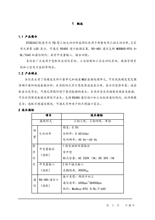
1概述1.1 产品简介DTSD342(配置号为7Q)型三相无功功率监测仪表用于测量电网三相无功功率,它采用大屏幕LCD显示,可通过RS485进行数据采集,RS-485通信支持MODBUS-RTU和DL/T645双通信规约;具有开关量输入、输出功能。
本仪表广泛适用于变配电自动化系统、工业控制和工业自动化系统、能源管理系统和小区电力监控等场合。
1.2 产品特点本仪表采用了高精度采样计量单元和高速MCU数据处理单元,可实现高精度宽范围准确计量和快速数据分析;采用段码式多行宽视角液晶显示屏,显示内容很丰富;液晶配备白色背光,可满足黑暗环境下查阅数据的要求;采用非易失存储器存储各类数据,可长时间保存数据且掉电不丢失;支持RS485通信端口和工业标准通信规约,组网便捷灵活;选配不同通信模块,可满足多种用户的不同接口需求。
2 技术指标3 功能介绍3.1参数测量功能本仪表可测量总和各分相无功功率。
3.2 越限报警功能(1)仪表具备越限事件报警功能。
用户可从电压、电流、功率、功率因数和频率等参数中最多同时选择6个数据作为检测对象,对其设定高低限值和判断条件,当测量值越过设定的限值时报警。
仪表带有1路继电器输出,当报警参数配置为某继电器输出且该继电器为自动方式(非手动方式)时,越限报警信号就可通过该路继电器输出(继电器合闸)。
(2)仪表内部最多可同时设置6组越限报警参数。
各组越限报警参数的配置流程为:选择检测数据类别→设置检测数据阀值→设置判断条件→选择报警信号输出继电器。
①各类检测数据代码如下:(DL/T645代码为十进制数;Modbus-RTU代码为十六进制数)当检测数据代码为FF时表示该组越限报警功能关闭。
②检测数据阀值:检测数据是否越限的判断阀值。
不同的数据类型有不同的单位,如:电压—V;电流—A,有功—KW,无功—KVAR,视在—KVA,频率—Hz。
③判断条件:设置为0表示大于限额值报警;1表示小于限额值报警。

T h e i n f o r m a t i o n p r o v i d e d i n t h i s d o c u m e n t a t i o n c o n t a i n s g e n e r a l d e s c r i p t i o n s a n d /o r t e c h n i c a l c h a r a c t e r i s t i c s o f t h e p e r f o r m a n c e o f t h e p r o d u c t s c o n t a i n e d h e r e i n .T h i s d o c u m e n t a t i o n i s n o t i n t e n d e d a s a s u b s t i t u t e f o r a n d i s n o t t o b e u s e d f o r d e t e r m i n i n g s u i t a b i l i t y o r r e l i a b i l i t y o f t h e s e p r o d u c t s f o r s p e c i f i c u s e r a p p l i c a t i o n s .I t i s t h e d u t y o f a n y s u c h u s e r o r i n t e g r a t o r t o p e r f o r m t h e a p p r o p r i a t e a n d c o m p l e t e r i s k a n a l y s i s , e v a l u a t i o n a n d t e s t i n g o f t h e p r o d u c t s w i t h r e s p e c t t o t h e r e l e v a n t s p e c i f i c a p p l i c a t i o n o r u s e t h e r e o f .N e i t h e r S c h n e i d e r E l e c t r i c I n d u s t r i e s S A S n o r a n y o f i t s a f f i l i a t e s o r s u b s i d i a r i e s s h a l l b e r e s p o n s i b l e o r l i a b l e f o r m i s u s e o f t h e i n f o r m a t i o n c o n t a i n e d h e r e i n .Product data sheetCharacteristicsABL8WPS24200regulated SMPS - 3-phase - 380..500 V AC -24 V - 20 AProduct availability: Stock - Normally stocked in distribution facilityMainRange of product Phaseo Product or component typePower supplyPower supply type Regulated switch modeInput voltage 380...500 V AC three phase L1, L2, L3Output voltage 24 V DC Rated power in W 480 WProvided equipment Power factor correction filter IEC 61000-3-2Power supply output current20 AOutput protection typeAgainst overload manual or automatic reset Against overvoltage 30...32 V, manual reset Against short-circuits manual or automatic reset Against undervoltage tripping if U < 21.6 V Thermal automatic resetAmbient air temperature for operation122…140 °F (50…60 °C) with derating factor)-13…122 °F (-25…50 °C) without)ComplementaryInput voltage limits 320...550 V Network frequency 47...63 Hz Inrush current 25 A 2 ms Cos phi 0.65Efficiency92 %Output voltage limits 24...28.8 V adjustable Power dissipation in W 38.4 W Line and load regulation 1...3 %Holding time>= 18 ms 400 V Permissible temporary current boost 1.5 x In for 4 s)Connections - terminalsDiagnostic relay removable screw terminal block 2 x 2.5 mm²Input connection screw type terminals 3 x 0.5...3 x 4 mm² AWG 22...AWG 12Input ground connection screw type terminals 1 x 0.5...1 x 4 mm² AWG 22...AWG 12Output connection screw type terminals 4 x 0.5...4 x 10 mm² AWG 22...AWG 8MarkingCEMounting support 35 x 7.5 mm symmetrical DIN rail 35 x 15 mm symmetrical DIN rail Operating position VerticalOperating altitude 6561.68 ft (2000 m)Output coupling Series ParallelName of testElectrostatic discharges EN/IEC 61000-4-2Induced electromagnetic field EN/IEC 61000-4-6Magnetic field EN 61000-4-8Primary outage IEC 61000-4-11Radiated electromagnetic field EN/IEC 61000-4-3Rapid transient IEC 61000-4-4Surge EN/IEC 61000-4-5Conducted emissions on the power line EN 55022 class B Radiated emissions EN 55022 class BHarmonic current emission EN/IEC 61000-3-2Status LED Output voltage 1 LED green and red)Output current 1 LED green, red and orange)Depth 6.30 in (160 mm)Height 5.63 in (143 mm)Width 3.78 in (96 mm)Net weight 3.53 lb(US) (1.6 kg)EnvironmentMTBF reliability320 V with UTE C80-810550 V with UTE C80-810Product certifications CCSAusEACULRCMStandards CSA C22.2 No 60950-1UL 508Environmental characteristic EMC EN 61000-6-1EMC EN 61000-6-3EMC EN 55024EMC EN/IEC 61000-6-4EMC EN/IEC 61204-3Safety EN 61204-4Safety EN/IEC 60950-1Safety SELVIP degree of protection IP20 EN/IEC 60529Ambient air temperature for storage-40…158 °F (-40…70 °C)Relative humidity0…90 % during operation0…95 % in storageOvervoltage category Class I VDE 0106-1Dielectric strength3500 V between input and ground4000 V between input and output500 V between output and groundOrdering and shipping detailsCategory22525 - ABL8 AND ABL7 POWER SUPPLIEDiscount Schedule CP12GTIN00785901666363Package weight(Lbs) 2.12 kg (4.67 lb(US))Returnability YesCountry of origin PHOffer SustainabilitySustainable offer status Green Premium productREACh Regulation REACh DeclarationEU RoHS Directive Pro-active compliance (Product out of EU RoHS legal scope)EU RoHS Decla-rationMercury free YesRoHS exemption information YesChina RoHS Regulation China RoHS DeclarationEnvironmental Disclosure Product Environmental ProfileCircularity Profile End Of Life InformationContractual warrantyWarranty18 monthsDimensions DrawingsRegulated Switch Mode Power Supplies DimensionsConnections and SchemaRegulated Switch Mode Power SupplyInternal Wiring DiagramRegulated Switch Mode Power SupplyLine Supply Wiring DiagramThree-phase (L1-L2-L3) 3 x 380 to 500 VRegulated Switch Mode Power SuppliesSeries or Parallel ConnectionSeries Connection(1)Two Shottky diodes Imin = power supply In and Vmin = 50 VParallel ConnectionNOTE: Series or parallel connection is only recommended for products with identical references.For better availability, the power supplies can also be connected in parallel using the ABL8RED24400 Redundancy module.Performance CurvesRegulated Switch Mode Power SuppliesDeratingThe ambient temperature is a determining factor that limits the power an electronic power supply can deliver continuously. If the temperature around the electronic components is too high, their life will be significantly reduced.The nominal ambient temperature for the Universal range of Phaseo power supplies is 50°C. Above this temperature, derating is necessary up to a maximum temperature of 60°C.The graph below shows the power (in relation to the nominal power) that the power supply can deliver continuously, depending on the ambient temperature.X Maximum operating temperature (°C)ABL 8RPM, ABL 8RPS, ABL 8WPS mounted verticallyDerating should be considered in extreme operating conditions:●Intensive operation (output current permanently close to the nominal current, combined with a high ambient temperature)●Output voltage set above 24 Vdc (to compensate for line voltage drops, for example)●Parallel connection to increase the total powerRegulated Switch Mode Power SupplyLoad LimitManual Reset Protection Mode(1)Boost 4sAutomatic Reset Protection Mode(1)Boost 4s“Boost” Repeat AccuracyThis type of operation is described in detail in the user manual, which can be downloaded from the website.。

前言本变频器采用SPWM控制方式/矢量控制方式,具有以下性能特点,可广泛使用于各类变频场合。
·超小尺寸结构设计·友好人机界面,方便参数设定·内含煞车回路·载波频率可调整·V/F 曲线可调整·跳跃频率设定·外部速度输入信号0-5V控制转速·多级速度控制·对地漏电保护·低噪音设计请详细参阅本说明书,以便正确安装使用,并做好日常保养与维护,延长使用寿命。
1、注意事项1.1必须由具有专业资格的人员才能对控制器进行调试、维修或检查。
操作前请仔细阅该使用手册。
1.2 确认输入电源处于完全断开的情况下,才能进行配线作业。
1.3 不要把输入端子(Z,Y,X)与输出端子(U,V,W) 混淆,否则会损坏变频器。
1.4 将变频器的接线地端子可靠接地,否则有触电危险。
1.5 通电情况下,不要用手触摸控制端子,否则有触电危险。
1.6 在充电指示灯彻底熄灭或正负母线电压在36V以下时进行,否则有触电的危险。
1.7 防止螺钉,垫片及金属之类的异物掉进变频器内部,否则有火灾及损坏财务的危险。
1.8 主回路接线用电缆端头的裸露部分,一定要用绝缘胶带包扎好,否则有损坏财物的危险。
2.标准规格3.操作面板图SEL键:左移键MENU:菜单键;RUN/STOP:运行/停止/确定键4.安装及使用为了更好使用变频器,延长其工作寿命,安装使用场合请注意以下几点:1、周围环境温度:-10℃-45℃,且通风良好。
2、不宜在滴水或过分潮湿的场合使用。
3、不宜在振动强烈,电磁干扰严重的场合使用。
4、较少尘埃、无腐蚀性液体的场合。
5、不宜在靠近易燃性物体的场合使用。
6、2台变频器不能上下一条直线上安装,尽量保持空气流通,散热良好;7、使用期间切忌用手接触内部器件。
8、要及时进行定期检修。
5.端子说明与配线6.机能说明机能设定一览表7.机能设定方法7.1菜单项的使用:按键次序 显示内容8.开关机操作:8.1按“RUN/STOP”键,面板控制有效时,运行/停止变频器工作。
PART NO.DESCRIPTIONITEM PART NO.DESCRIPTION ITEM This parts list must be left with owner, hung on or adjacent to the boiler Owner should retain parts list for future reference.PART NO.DESCRIPTIONITEM795124000 M1 (S2, LB): CENTER PARTITION CLINCH NUT ASSY201790010000 M1 (S2, LB): RELAY PARTITION202790008000 M1 (S2, LB): SERVICE PARTITION203790018000 M1 (S2, LB): BRACKET ASSEMBLY - LINE VOLTAGE (120V)204790013000 M1 (S2, LB): BRACKET - LOW VOLTAGE TERMINAL (24V)205790009000 M1, M2: GAUGE HOUSING206790909000 M1: MOUNTING BRACKET FOR HONEYWELL CONTROL207790311000 CIRCUIT BREAKER BASE- SINGLE PHASE 125A208790312000 CIRCUIT BREAKER BASE- SINGLE PHASE 200A209790313000 CIRCUIT BREAKER BASE- THREE PHASE210790335100 CIRCUIT BREAKER 15A SP GE THQL1115211790314000 CIRCUIT BREAKER 25A DP GE THQL2125212790315000 CIRCUIT BREAKER 30A DP GE THQL2130213790316000 CIRCUIT BREAKER 50A DP GE THQL2150214790317000 CIRCUIT BREAKER 60A DP GE THQL2160215790343000 TRANSFORMER: 40VA-120/24V W/TERMINALS216790344100 TRANSFORMER: 50VA-120/24V W/TERMINALS217790322000 CONTACTOR HONEYWELL R8246A1004 24V218790847000 TIME DELAY RELAY 15SH1 309572219790339000 M1: TERMINAL BLOCK ASSEMBLY 4 POLE (LINE VOLTAGE) 120V221790340000 M1: TERMINAL BLOCK ASSEMBLY 6-POLE (LOW VOLTAGE) 24V222790567000 DOUBLE TERMINAL CONNECTOR223790280000 EQUIPMENT SOLDERLESS LUG 2/0 AWG225790281000 SCREW 1/4-20 X 5/8 HEX ZN PLATED GRADE 5226PART NO.DESCRIPTIONITEM790379000 HONEYWELL AQUASTAT L7248L1105 (100°-240°F HI-LIMIT)228790834000 SCREW 8x3/8 HEX WASHER ZN PLATE TYPE B22965 0666 000GROUND SCR10-32x3/8 GREEN GND230790913000 SCREW 8 X 1/2 HEX WASHER SLOT ZINC TYPE B233790838000 WASHER-TERMINAL CUP #10 BRASS234790139000 STUD 1/4-20 X 3/4 ZINC PL.238790266000 STANDOFF INSULATOR 1" (1/4-20 X 5/16)239790285000 HEX HEAD CAP SCREW 1/4-20 X 3/8 ZN PLATED GRADE 524050 0385 000SNAP BUSHING Ø7/8" HOLE X .69" ID245500373000 SNAP BUSHING Ø1.125 HOLE X .875" ID246790858000 "GROUND" LABEL - SMALL248790863000 M1: LABEL - LOW VOLTAGE TERMINAL BLOCK (24V)249790862000 M1: LABEL - LINE VOLTAGE TERMINAL BLOCK (120V)250790849000 LABEL "L1, L2"251790845000 LABEL "NEUTRAL"252790864000 LABEL "L1" SMALL254790865000 LABEL "L2" SMALL255790866000 LABEL "L3" SMALL256790286000 SCREW 10-32 X 3/8" PAN HD PHILLIPS ZN PLT259790914000 SCREW 8-32 X 5/8" PAN HD PHILLIPS ZN THREAD FORMING260790406000 HONEYWELL SENSOR 24" LONG277M1 (S2): ELECTRIC PARTITION ASSEMBLIES1-PHASE S2 ELECTRIC PARTITION (SMALL BASE)1 PHASE S2 & S2M ELECTRIC PARTITION (LARGE BASE)MODELS EH 24 TO EH 40DETAIL BB*** ADDITIONAL TDR - S2M ONLY229228207248225252240226225239238203206229245259208201219216218260249222202260221250230234229245246245229205212 - 215251************MODELS EH 8 TO EH 2022925924624627722920624520320927720117248225252251228246219249223236222205229204234229245246245236230248250233211212-215207235229229219223***2212181PH & 3PH LB ELECTRIC PARTITIONPART NO.DESCRIPTIONITEM795124000M1 (S2, LB): CENTER PARTITION ASSY201790010000M1 (S2, LB): RELAY PARTITION 202790008000M1 (S2, LB): SERVICE PARTITION203790018000M1 (S2, LB): BRACKET ASSEMBLY - LINE VOLTAGE (120V)204790013000M1 (S2, LB): BRACKET - LOW VOLTAGE TERMINAL (24V)205790009000M1, M2: GAUGE HOUSING206790909000M1: MOUNTING BRACKET FOR HONEYWELL CONTROL207790387002MINI POWER DISTRIBUTION BLOCK SINGLE PH. 2-POLE 175A(UL)208790387003MINI POWER DISTRIBUTION BLOCK 3-PHASE 3-POLE 175A(UL)209790343000TRANSFORMER: 40VA-120/24V W/TERMINALS 216790344100TRANSFORMER: 50VA-120/24V W/TERMINALS217790322000CONTACTOR HONEYWELL R8246A1004 24V 218790847000TIME DELAY RELAY 15SH1 309572219790339000M1: TERMINAL BLOCK ASSEMBLY 4 POLE (LINE VOLTAGE) 120V 221790340000M1: TERMINAL BLOCK ASSEMBLY 6-POLE (LOW VOLTAGE) 24V 222790567000DOUBLE TERMINAL CONNECTOR223790914000SCREW 8-32 X 5/8" PAN HD PHILLIPS ZN THREAD FORMING224PART NO.DESCRIPTIONITEM790280000EQUIPMENT SOLDERLESS LUG 2/0 AWG225790281000SCREW 1/4-20 X 5/8 HEX ZN PLATED GRADE 5226790379000HONEYWELL AQUASTAT L7248L1105 (100°-240°F HI-LIMIT)228790834000SCREW 8x3/8 HEX WASHER ZN PLATE TYPE B 22965 0666 000GROUND SCR10-32x3/8 GREEN GND230790913000SCREW 8 X 1/2 HEX WASHER SLOT ZINC TYPE B 231790838000WASHER-TERMINAL CUP #10 BRASS234790139000STUD 1/4-20 X 3/4 ZINC PL.238790266000STANDOFF INSULATOR 1" (1/4-20 X 5/16)239790285000HEX HEAD CAP SCREW 1/4-20 X 3/8 ZN PLATED GRADE 524050 0385 000SNAP BUSHING Ø7/8" HOLE X .69" ID245500373000SNAP BUSHING Ø1.125 HOLE X .875" ID 246790858000"GROUND" LABEL - SMALL248790863000M1: LABEL - LOW VOLTAGE TERMINAL BLOCK (24V)249790862000M1: LABEL - LINE VOLTAGE TERMINAL BLOCK (120V)250790849000LABEL "L1, L2" 251790845000LABEL "NEUTRAL"252790851000"L3" LABEL (3-PHASE MODELS ONLY)253790846000"GROUND" LABEL257790286000SCREW 10-32 X 3/8" PAN HD PHILLIPS ZN PLT 259790406000HONEYWELL SENSOR 24" LONG277M1 (LB): ELECTRIC PARTITION ASSEMBLY229234230248230250221224204246202229205222249218207229228207229216217219201229206245203246240225257253251231209208238239252226**** ITEM 216 UP TO 20KW ITEM 217 ABOVE 20KW259229224277PART NO.TITLEITEM796002400 HEAT EXCHANGER 4-HOLE301796002600 HEAT EXCHANGER 6-HOLE302796002800 HEAT EXCHANGER 8-HOLE303790304000 HEATER ELEMENT 4kW 240V304790305000 HEATER ELEMENT 5kW 240V305790306000 BLANK SCREW PLUG306790303000 HEATER ELEMENT GASKET307902179051 REDUCING BUSHING 1/2 x 1/4 (BL.MALLEABLE)308910373061 TRIDICATOR309790398000 HIGH LIMIT CONTROL SENSOR310790106000 COUPLING EXTENTION 1/2 x 1/2311790099000 IMMERSION WELL 1/2" NPT X 1.5"312790119000 H-CLIP WIRE RETAINER FOR IMMERSION WELL313400239000 1/2" NPT PLUG-SQUARE HEAD314301302303314304305307306307311308309310 313 312 314M1, M2: HEAT EXCHANGER ASSEMBLYModel TypeElements*CB1CB2CB3CB4CB5EH8-135-S21P2E 2 X 4kW15A 50A ---EH9-135-S21P2E 1X4kW,1X5kW 15A 50A ---EH10-135-S21P2E 2 X 5kW 15A 60A -- EH12-135-S21P3E 3 X 4kW 15A 50A 25A --EH15-135-S21P3E 3 X 5kW15A 60A 30A --EH16-135-S21P4E 4 X 4kW 15A 50A 50A --EH18-135-S21P4E 2X4kW,2X5kW 15A 50A 50A --EH20-135-S21P4E 4 X 5kW 15A 60A 60A --M1 (S2): SINGLE PHASE CONFIGURATIONS*kW values are 240V ratingsCB2CB3CB4CB1CB5Model Type Elements*CB1CB2CB3CB4CB5EH12-345-S23P3E 3 X 4kW 15A 25A 25A 25A -EH15-345-S23P3E 3 X 5kW 15A 30A 30A 30A -EH16-345-S23P4E 4 X 4kW15A 25A 25A 50A -EH18-345-S23P4E 2X4kW,2X5kW15A 25A 30A 50A -EH20-345-S23P4E 4 X 5kW15A 30A 30A 60A -EH24-345-S23P5E 4X5kW, 1X4kW 15A 50A 30A 60A -EH25-345-S23P5E 5X5kW15A 60A 30A 60A -EH28-345-S23P6E 4X5kW, 2X4kW 15A 50A 50A 60A -EH30-345-S23P6E 6X5kW15A 60A 60A 60A -EH32-345-S23P7E 4X5kW, 3X4kW 15A 30A 50A 50A 50A EH35-345-S23P7E 7 X 5kW 15A 30A 60A 60A 60A EH40-345-S23P8E 8 X 5kW15A 60A 60A 60A 60AM1 (S2): THREE PHASE CONFIGURATIONSCB4CB3CB2CB1CB1CB5CB4CB3CB2ModelTypeElements*CB1CB2CB3CB4CB5EH24-135-S21P5E 1X4kW,4X5kW 15A 50A 30A 60A -EH25-135-S21P5E 5 X 5kW15A 60A 30A 60A -EH28-135-S21P6E 2X4kW,4X5kW 15A 50A 50A 60A -EH30-135-S21P6E 6 X 5kW15A 60A 60A 60A -EH32-135-S21P7E 3X4kW,4X5kW 15A 30A 50A 50A 50A EH35-135-S21P7E 7 X 5kW 15A 30A 60A 60A 60A EH40-135-S21P8E8 X 5kW15A 60A 60A 60A 60ACB1CB2CB31P2E 1P3E 1P4E1P5E 1P6E 1P7E 1P8E3P3E 3P4E 3P5E 3P6E3P7E 3P8EEH8 - EH20 1-PHASE SMALL BREAKER BASEEH24 - EH40 1-PHASE LARGE BREAKER BASEEH 12 - EH 30 3-PHASE BREAKER BASEEH 32 - EH 40 3-PHASE BREAKER BASEFOR MODEL SPECIFIC ELEMENT & COMPONENT CONFIGURATIONS SEE ELECTRIC DIAGRAMINSIDE THE RIGHT FRONT COVERSingle Phase Models Model Type Elements*EH8-135-LB 1P2E 2 X 4kWEH9-135-LB 1P2E 1X4kW,1X5kW EH10-135-LB 1P2E 2 X 5kW EH12-135-LB 1P3E 3 X 4kW EH15-135-LB 1P3E 3 X 5kW EH16-135-LB 1P4E 4 X 4kWEH18-135-LB 1P4E 2X4kW,2X5kW EH20-135-LB 1P4E 4 X 5kWEH24-135-LB 1P5E 1X4kW,4X5kW EH25-135-LB1P5E5 X 5kWThree Phase ModelsModel Type Elements*EH12-345-LB 3P3E 3 X 4kW EH15-345-LB 3P3E 3 X 5kWEH16-345-LB 3P4E 4 X 4kWEH18-345-LB 3P4E 2X4kW,2X5kW EH20-345-LB 3P4E 4 X 5kWEH24-345-LB 3P5E 4X5kW, 1X4kW EH25-345-LB 3P5E 5X5kWEH28-345-S23P6E 4X5kW, 2X4kW EH30-345-S23P6E 6X5kWEH32-345-S23P7E 4X5kW, 3X4kW EH35-345-S23P7E 7 X 5kW EH40-345-S23P8E 8 X 5kWM1 (LB): SINGLE PHASE CONFIGURATIONSM1 (LB): THREE PHASE CONFIGURATIONS1P2E 1P3E 1P4E 1P5E EH LB SINGLE PHASE MODELS3P3E3P4E 3P5E 3P6E*kW values are 240V ratings*kW values are 240V ratings3P7E 3P8E EH LB THREE PHASE MODELSFOR MODEL SPECIFIC ELEMENT & COMPONENT CONFIGURATIONS SEE ELECTRIC DIAGRAMINSIDE THE RIGHT FRONT COVER91929192SLANT/FIN CORPORATION, Greenvale, N.Y. 11548 • Phone: (516) 484-2600FAX: (516) 484-0933•Canada: Slant/Fin LTD/LTEE , Mississauga, OntarioW e B ui l d T r u s t a n d C o m f o r tPUBLICATION: EH-S2-10PL Rev B • Printed in U.S.A. 617 • Part No. 790922000EH-24-135-S2M TO EH40-135-S2M1P8E1P7E 1P6E 1P5E M1 (S2M): SINGLE PHASE CONFIGURATIONSModel TypeElements*CB1CB2CB3CB4CB5EH24-135-S2M 1P5E 1X4kW,4X5kW 15A 50A 30A 60A -EH25-135-S2M 1P5E 5 X 5kW15A 60A 30A 60A -EH28-135-S2M 1P6E 2X4kW,4X5kW 15A 50A 50A 60A -EH30-135-S2M 1P6E 6 X 5kW 15A 60A 60A 60A -EH32-135-S2M 1P7E 3X4kW,4X5kW 15A 30A 50A 50A 50A EH35-135-S2M 1P7E 7 X 5kW 15A 30A 60A 60A 60A EH40-135-S2M1P8E 8 X 5kW15A 60A 60A 60A 60A219FOR MODEL SPECIFIC ELEMENT &COMPONENT CONFIGURATIONS SEE ELECTRIC DIAGRAMINSIDE THE RIGHT FRONT COVERCB2CB3CB4CB5CB1TDR IN THIS POSITIONON M1 S2M ONLY。
一、重要类型及使用条件1、机组类型:1)原则型、自动并车、ATS自动切换、箱式防雨型、静音型、拖车电站、车载电站等。
2)电源种类:交流3)额定转速:1500转/分 1800转/分4)额定频率:50赫兹(60赫兹可选)5)额定电压:400伏/230伏-660伏6)功率原因:cos0.8滞后7) 相数:三相四线制8)励磁方式:相复励-无刷自励9)冷却方式:水箱风扇2、使用条件:(保证输出额定功率)1)海拔高度不超过1000m;2) 环境温度+5℃-+38℃;3)空气相对湿度不不小于60%(25℃时);4)无导电尘埃及能破坏金属及绝缘旳腐蚀性气体场所;5)没有爆炸危险旳场所;6)没有震动和颠簸旳场所,垂直斜度不超过5°;7)无日晒、雨淋旳场所;8)按照发动机阐明书规定使用高品质柴油、机油、冷却液;9)机组和箱体必须接地。
3、输出功率1)当环境温度为+20℃,海拔高度在1000m如下,外界大气压力为760mmHg,大气相对湿度为60%。
机组能保证额定功率长期持续运转;2)机组在海拔高度不超过1000m,环境温度不超过38℃工作时,容许在8h 内按额定功率旳100%负荷运行;3)机组在海拔高度超过1000m时,每升高300m功率应减少4%,环境温度超过38℃时,每升高1℃功率应减少2%;4)若超过上述1个环境条件下时,柴油机、发电机输出功率应进行修正。
4、机组电气性能指标注:(1)机组0-25%额定负载下,其电压和频率旳波动率容许比表列数值大0.5。
(2)计算稳态电压调整率时,不包括从冷态到热态旳电压变化,热态指机组在额定方式下经持续运行试验下旳状态。
二、操作指南1、机组启动前旳准备目视检查目视检查只需要花费几分钟时间,但却可防止代价昂贵旳维修和事故(非常重要)1、检查柴油发电机组多种机械联接和紧固件与否有松动现象;检查各运动件转动与否灵活,有无相擦卡死等现象。
有无阻碍机组运转旳杂物,若有应清除。
HY系列核电用(NC级)三相异步电动机使用说明书(机座号80~355)1 概述1.1 本说明书提供了HY系列核电用(NC级)三相异步电动机及其派生的系列电动机的收货、贮存、安装、运行及维护方面的说明及指导。
1.2 产品特点及适用范围HY系列核电用(NC级)三相异步电动机(机座号80~355)(以下简称电动机)是结合我公司几十年生产核用电动机的实践经验而设计制造的,具有结构紧凑、效率高、可靠性高、噪声低、重量轻、安装维护方便等优点。
本系列电动机适用于核电厂潮湿、腐蚀、有辐照要求的场所。
1.3 电动机型号的含义电动机型号的组成及含义举例如下:HY 200 S - 8极数机座长度(S表示短机座、M表示中机座、L表示长机座)中心高核电用三相异步电动机2 电动机现场运行条件2.1 海拨海拨不超过1000m。
注:如电动机在海拔超过1000m或最高环境空气温度高于40℃的条件下使用时,电动机的温升按GB755-2000《旋转电机定额和性能》规定予以修正。
2.2 最高环境空气温度电动机应在环境温度为-15℃-+40℃下使用。
此时不需附加任何标志。
若环境温度超出上述范围应视为特殊情况,制造厂应将环境温度范围在技术条件中给出并在铭牌上给出符合温度条件的范围。
如:-30℃ Ta +40℃。
2.3 最湿月月平均最高相对湿度为90%,同时该月月平均最低温不高于25℃。
3 电动机的结构型式及参数3.1 结构电动机总体结构见图1。
第二位表征数字表示由于外壳进水而引起有害影响的防护等级(见表2)。
3.3 电机冷却方法为IC411,全封闭自扇冷式。
冷却方式的标志由表征字母“IC”及附加在后面的三个表征数字组成。
举例如下:IC 4 1 1次级冷却介质(1表示自循环)初级冷却介质(1表示自循环)冷却回路布置(4表示机壳表面冷却)国际通用冷却符号3.4 电动机的安装方式电动机的安装代号由“国际安装”(International Mounting)的缩写字母“IM”表示,代表“卧式安装”的大写字母“B”或代表“立式安装”的大写字母“V”连同1位或2位阿拉伯数字组成。
三相5-8KW电磁感应加热控制器规格书
一、产品电气规格
1、额定电压频率:AC 380V / 50Hz
2、电压适应范围:310V~430V
3额定功率:5-8KW
二、环境适应能力
1、温度:-20℃~50℃;
2、湿度:≤95%
三、基本性能概述
1、电流与电压特性:恒流输出;
2、热效率≥90%;
3、IGBT过热保温度:95±5℃;
4、工作频率:16-25KHz;
5、半桥式串联谐振;
6、具有软启动加热/停止模式;
7、具有加热线圈短路保护功能;
8、具有一个精度为10位温度检测口,检测温度范围0-150℃;
9、具有多个线圈叠加功率达100KW以上工作而互不干扰;
10、实物尺寸均为:长220*宽200*高110(散热风扇需另外装,随身配套一
个380V150mm的散热风扇)
11、平均无故障时间10000小时以上
四、系统接线说明及示意图
1、一个指示灯:正常工作时:指示灯长亮;没负载时:指示灯亮0.5S,灭0.5S
循环;不加加热工作机为熄灭。
电压过高时:指示灯亮1次
电压过低时:指示灯亮2次
IGBT温度传感器断:指示灯亮4次
IGBT模块温度超温:指示灯亮6 次
指示灯显示规律是保护的数字对应亮0.5S,灭1S的次数.停时间为2S。
2、T—MAIN此端子是用来启动/停止的。
当处于开路时是工作的;当闭合时是
停止的(也可以设置为当处于闭合路时是工作的,当开路时是停止的)。
用户也可以不用它。
要想停止它,断开它的总电源即可。
3、RW此端子是用来接调节功率。
4、A、B 、C是三相三线制电源输入。
5、线圈A和线圈B是接加热线圈。
6、线圈参考参数:云母绕包玻璃纤维编织耐高温电缆。
5KW横截面6mm2(注:炮筒在常温下电感量测190 uH,在高温下电感量测200 uH,因为炮筒电感量在常温与在高温下是不一样的,炮筒温度越高,电感量越大,炮筒温度越低,电感量越小。
这样板会工作在最佳状态。
)保温棉厚度约为15-20mm。
(注:线圈用在螺杆时厚度控制在18毫米,线圈用在贴片中时,厚度用10毫米高温棉,电感量取200 uH,这样板会工作在最佳状态。
)
8KW横截面10mm2,电感量为190uH,(注:炮筒在常温下电感量测190 uH,在高温下电感量测200 uH,因为炮筒电感量在常温与在高温下是不一样的,炮筒温度越高,电感量越大,炮筒温度越低,电感量越小。
这样板会工作在最佳状态。
)保温棉厚度约为15-20mm(注:线圈用在螺杆时厚度控制在18毫米,在绕贴片空心线圈时,厚度用10毫米高温棉,电感量取200 uH,这样板会工作在最佳状态。
)。