中英文文献翻译-重型越野汽车断开式驱动桥的研发
- 格式:doc
- 大小:45.50 KB
- 文档页数:8

摘要本设计首先确定各主要部件的结构型式和主要设计参数,然后参考同类的驱动桥结构,确定出设计方案并进行计算和设计,最后对主从动锥齿轮、半轴齿轮、半轴、桥壳轮边机构等部分进行校核,对支撑轴承进行了寿命校核。
本设计采用主减速器和轮边减速器双级传动副传动,均匀分配单一传动副上的高强度磨损,轮边机构的应用,大大的提高了离地间隙,提高了汽车的通过性。
本设计在我国尚处于起步阶段,在我国仍有很大的发展潜力和发展空间,本设计也将是未来越野汽车和重载汽车的发展方向。
本设计具有以下的优点:由于采用轮边双级驱动桥,使得整个后桥的结构简单,制造工艺简单,从而大大的降低了制造成本。
并且,提高了汽车的离地间隙。
关键字:越野汽车;后桥;轮边双级;圆弧齿锥齿轮AbstractThis design is to first identify major parts of the structure and main design parameters, then reference to similar axles structure, confirmed the design and calculation and design, final master—slave dynamic bevel gear and half axle gears, half axle, bridge housing wheel edges institutions, to test the part such as back-up bearing life respectively。
This design USES the main reducer and wheel edges reducer doublestage transmission vice transmission, evenly distributed single transmission of high intensity vice wear, wheel edges institutions of applications,greatly improve the ground clearance is achieved, improved the car through sexual.This design in our country is still at the beginning, in our country still has great potential for growth and development space, this design also will be the future off-road vehicle and heavy—load automobiledevelopment direction。


断开式驱动桥的名词解释断开式驱动桥是一种用于汽车或者其他车辆的传动系统,它的主要作用是将发动机的输出动力进行分配,同时允许车轮独立转动。
在这篇文章中,我们将对断开式驱动桥进行详细的解释,包括其原理、结构和应用。
一、原理断开式驱动桥是指通过一定的机械设备和传动元件,将发动机的动力传递到各个车轮上。
与传统固连式驱动桥不同,断开式驱动桥允许车轮独立运动,以适应不同路况和行驶状态。
它可以提供更好的操控性和行驶性能,特别是在越野或多种路况环境下。
二、结构断开式驱动桥通常由以下几个主要组成部件构成:1.差速器:差速器是连接两个车轮的主要传动组件之一。
它通过分配动力,使两个车轮在转弯时可以以不同的速度旋转,确保车辆的稳定性和操纵性。
2.半轴:半轴将差速器的输出动力传递到各个车轮上。
它们通常由坚固的金属制成,具有足够的强度和刚性来承受车辆的重量和力量。
3.驱动轴:驱动轴是将发动机的动力传输到差速器的传动元件。
它负责将发动机的扭矩传递给差速器,然后再分配给各个车轮。
4.轮毂:轮毂是车轮与车辆其他部分的连接点。
它负责支撑车辆的重量,并提供转动运动。
通过断开式驱动桥,车轮可以独立运动,轮毂必须能够与其他部件灵活连接。
三、应用断开式驱动桥主要用于需要更高悬挂和较强越野能力的车辆上。
例如,越野车、农用车、工程车等。
由于断开式驱动桥的设计,车轮可以独立运动,每个车轮都可以根据路面状况调整自己的转速和扭矩分配,以达到更好的通过性和操控性能。
这对于需要经常面对复杂路况的车辆来说非常重要。
此外,断开式驱动桥还可以用于一些特殊用途的车辆,例如军事车辆、消防车辆等。
这些车辆通常需要高度可靠性和出色的越野能力,以应对各种应急情况。
结语断开式驱动桥是一种用于车辆传动系统的关键组件。
它通过允许车轮独立运动,提供了更好的操控性和越野性能。
由于其设计和结构的特殊性,断开式驱动桥主要用于一些需要更高越野性能和适应复杂路况的车辆上。
通过了解和研究断开式驱动桥的原理和结构,人们可以更好地理解和应用这种传动系统,从而改善车辆的性能和可靠性。

AUTOMATIC TRANSMISSION & TRANSAXLEOVERVIEWby Kyle McFaddenAutomatic transmissions are highly complex hyrdomechanical devices. Diagnosing and repairing them requires nothing less than an ASE master mechanic. The automatic transmission provides automated selection of forward gears in a motor vehicle. The automatic transmission is able to select the correct forward gear for efficient engine operation based on vehicle speed, throttle position, and engine load. The automatic transmission components consist of transmission case, torque converter, fluid pump, planetary gear set, clutch packs and/or band assemblies, control valves, transmission mainshaft, extension housing and various small parts.The transmission case is manufactured of cast aluminum. It houses the internal components of the automatic transmission and provides a mounting surface for attachment to the engine block. The torque converter is bolted to a type of flywheel called a flex plate. The flexplate in turn, is bolted to the rear of the crankshaft. The torque converter provides a means to transmit engine power into the transmission.Refer to an auto repair manual for a diagram showing the details of your vehicle’s torque converter assembly.The torque converter is a doughnut shaped device that is filled with fluid. When the engine is running, the torque converter spins, rotating and pressurizing the fluid using internally mounted blades. The spinning fluid rotates a turbine that is connected to the transmission mainshaft. A separate internal set of blades called a stator helps to direct the fluid into the turbine. The operation of the torque converter can be compared to a powered air fan spinning a non powered air fan. The powered fan will generate moving air, directed at the non powered fan blade, causing it to rotate. The powered fan becomes the driving member, while the non powered fan becomes the driven member. If the air is moving slow enough, very little torque is transmitted from the driving member to the driven member. If you wanted, you could easily stop the rotating fan blade of the non powered fan. However, if the powered fan were to operate at high speed, the non powered fan would be rotating at a much higher speed, making it more difficult to stop. This is the same principal that allows an automatic transmission equipped vehicle to idle in gearand drive down the road without using a mechanical clutch. At idle speed, fluid pressure is low, transmitting very little engine torque through the transmission. When the engine speed is raised, fluid speed and pressure increases, allowing more engine torque to be directed to the transmission. Most torque converters contain an internal locking clutch that is applied at cruise speed. This clutch, called a torque converter clutch, eliminates the slippage that occurs with a torque converter. The torque converter clutch is used as a fuel saving device, and to reduce the amount of heat generated in the transmission. When troubleshooting poor MPG issues, one culprit is a faulty torque converter, though poor MPG would also be present with shifting issues if the torque converter is the cause.Forward speeds and reverse are provided by a gear set called the planetary gears. The planetary gear set consists of a central gear, called the sun gear, placed inside a large gear called an internal gear. Rotating between the internal gear and the sun gear, are small gears, held in a carrier, known as planetary gears. Different gear ratios are made possible by holding one component of the planetary gear set and allowing the other to rotate. For example, if the sun gear were held, the internal gear would be rotated by the planetary gears revolving around the motionless sun gear. This would cause the internal gear to rotate at low speed, while the planetary gears move much faster. This would provide a low gear function for the transmission, since the slow moving internal gear would be used to transmit power to the driving wheels.An internal transmission oil pump is driven by the rotation of the torque converter. The oil pump pressurizes and circulates the transmission fluid used for the operation and lubrication of the transmission. The pressure created by the pump is often referred to as line pressure. Line pressure is utilized by the transmission to signal shift points and operate various transmission components.Bands and clutches are used to hold the components of the planetary gear set to in order to provide different forward gear ratios or reverse. They are operated by line pressure that is directed to a specific band or clutch pack by the transmission shift control valves. The shift control valves operate by responding to changes in linepressure based upon the operation of input devices that signal road speed, throttle position, and engine load. Correcting shifting issues may not involve a costly auto repair job; it may be as simply as adjusting the bands.The input devices used for transmission shift control are the governor, throttle valve, and vacuum modulator. The governor provides road speed information to the transmission to control shift points. It works by increasing line pressure as road speed increases. The throttle valve is connected by linkage to the throttle of the engine. The throttle valve modifies line pressure based on throttle position. This information is needed to vary shift points in response to driving conditions. When the throttle is moved to wide open, the throttle valve will cause send a line pressure signal to the control valves to delay shifting until higher road speed. The vacuum modulator changes shift feel in response to engine load. Since engine intake manifold vacuum changes in response to engine load, manifold vacuum is used as an input signal to the transmission. The vacuum modulator receives vacuum signal from the engine. The vacuum modulator will increase line pressure to stiffen transmission shifting based during heavy engine loads. The increased line pressure will cause clutches and bands to hold tighter and help to diminish slipping.Most vehicles today are equipped with automatic transmissions that use electronic shift controls. The operation of the electronically controlled transmission is similar in principle to the non electric transmission. However, the electronically shifted transmission uses input signals from the vehicle control module to control shift points, rather than a governor and throttle valve. The vehicle control module controls transmission shifting based on engine and transmission data sensors. The throttle position sensor is used in place of the mechanical throttle valve. The vehicle speed sensor is used to replace the governor. Engine load sensors, such as a manifold pressure sensor, are used to control shift feel. A vacuum modulator may still be used by some vehicle makes to assist in shift control. The vehicle control module will utilize this information to operate various shift control solenoids inside the transmission. These shift control solenoids in turn control line pressure to theirrespective shift control valves that in turn apply or release pressure to bands or clutches.The result of using electronic shift controls is an automatic transmission that operates more efficiently to tailor shifting to meet engine demands. Fuel economy and vehicle emission control are enhanced by more precise control of the automatic transmission. Vehicle control modules have the ability to adapt transmission shifting to meet the individual driving patterns of the vehicle. Also internal overheat protection is provided for by the control module’s ability to monitor transmission fluid temperature and change transmission shifting and operation to minimize temperature related damage. On many vehicles, the EEC (Electronic Engine Control) will “learn” a particular driver’s driving style. This information is stored in the EEC’s memory. If the battery is disconnected (during replacement, for example), the vehicle may shift erratically for a short time until the EEC re-learns the driver’s driving style and then reprograms itself. This is important to remember and a little patience can save you a trip to the auto repair shop, ie. after your battery is replaced, drive your vehicle for a day or so and see if the erratic shifting issue is resolved (most likely it will correct itself).The automatic transaxle is an automatic transmission that also contains the final drive for delivering power to the driving wheels. Operation is comparable to the operation of the conventional automatic transmission. With the exception of a differential and axle shafts located in the lower portion of the transaxle. The automatic transaxle is used almost exclusively in front wheel drive vehicles..自动变速器与驱动桥概述自动变速器是高度复杂的精密设备。
附录附录AHeavy Off-Road Vehicle Drive Axle Of BreakingThe important thing is, in the great assembly at the end of the transmission. Its basic function is increased by the transmission shaft or directly by the torque, came to the torque distribution to left and right drive wheels, and make the right and left wheel drive car has required the kinematics differential function, While carrying the spring load and the car wheel, the frame of the body through suspension or integral to plumb-lines, longitudinal and transverse force and moment force, Also the biggest transfer transmission torque, still under the bridge housing reaction torque.Drive structure and driving wheel is closely related to the suspension structure. When driving wheel using an independent suspension, using the broken open axles, When driving wheels adopt independent suspension, match with breaking drive axles, independent suspension. Look from exterior, independent suspension axles connectionless left and right of the whole bridge rigid driving wheel, shell is bridge housing, and other relative movement between. This bridge is installed in the middle frame or integral car transmission and driving wheel transmission device and part of the quality of the automobile suspension with belong to the quality and the side of the drive wheels with independent suspension of elastic component and frame or weak connection for cars. Therefore, one on either side of the drive wheels can independently, relative to the frame or cars do, swing, left, and right shaft corresponding requirements and their corresponding shell makes the corresponding swing. Cars drive by breaking the suspension, and the quality of small and independent suspension matching, can make the driving wheels of various earthing and adaptability, good roads that can greatly reduce the cars in the rough road impact and vibration during the body decreases wheel and axle tilt, the dynamic loads of vehicle, improve and enhance average speed, Reduce the damage, improve its components reliability and prolong its service life.Based on the development of China's heavy independent suspension of six x 6 cross-country car cut off from the drive axles, for example, is insufficient, the development technology independent suspension drive axle of necessity and independent suspensiondrive axle of structural principle in aspects of heavy off-road vehicle drive with independent suspension of this development.1 Domestic independent suspension drive technology situationAt present domestic independent suspension axles in cars, light off-road vehicle and JN252 8 x 8, etc ZhongDunWei military car has been applied and independent suspension heavy off-road vehicle axles technology is basically blank, Foreign independent suspension heavy off-road vehicle axles technology also only by American company, belarus, Minsk Sisu, Finland has TIMONEY company and Korea etc, and application scope of military and civilian limitations in some special models.2 Develop independent suspension drive axle of necessityIn recent years, with independent suspension off-road vehicle market demand more and more widely. Restrict independent suspension off-road vehicle development is one of the key factors, thus breaking drive axles of the necessity of developing broken off.2.1Military car development needsCurrently our extensive use of grade 6 x 6 type 7t SX2190 models is shaanxi automobile manufacturing factory using STEYR technology development of new generation rover, has good performance, and strong adaptability, good performance advantages over the past 20 years for national defense construction made great contribution. The truck with 8 x 8 upward-leading continuous casting.the JN2270 15t and capability of type x 8 August JN2300 type, the successful development of China's second DaiJun car development was at an end. In order to adapt to the needs of modern war, the third DaiJun car development was put on the agenda. Article DaiJun car features for independent suspension of high performance of motor vehicles. As its core technology is one of the big Hollywood drive shaft cut off, domestic blank, basic is dependence on imports, if do not accord with national also does not conform to the military.2.2The basic needs of national constructionFor many years, our national economy is developing rapidly, and infrastructure investment growth, hydroelectric power, oil field, mine, coal and other industries such as fire like tea. The industry is inseparable from the high quality, the high performance of transport vehicles, independent suspension off-road vehicle is among the top. However, these vehicles almost entirely on imports, spent a great deal of foreign exchange. To develop a replacement model is of great significance to meet the market demand.3 Independent suspension structure theory. Drive axle ofChina's heavy automobile group company with development and production status, independent development drive axle of the independent suspension 6 x 6 cross-country car drive shaft cut off big Hollywood. According to 6 x 6 independent suspension chassis design requirements, in this model adopted high transmission fault type axles. The first thing is to cut off to drive, high of double bridge for breaking through the medium-sized Bridges, rear axles turn for breaking steering of high axles. Three bridge are installed with gas control differential between the wheel lock differential, medium-sized Bridges across the bridge box installed with gas control differential between the lock shaft differential. Main reducer ratio for 1 2023, gear ratio for 4. 26 (belt wheel side filling put gas system, ABS), the total ratio 7.016, The medium-sized Bridges for Φ 180 input end tooth flanges, output for Φ 165 end flange, rear axle gears before the input for Φ 165 end tooth flange, Each shaft axis for jose 13t. This design is mainly in steyr drive technology based on the development and design, design thoughts and 6 x is 6, 8 x 8, 10 December 10, military USES 10 series assemblies, reduce the new design of special parts. 8 x 8 middle bridge, 10 assembly, 10, and 12 million spxillion structure types are similar. The new design two broken open bridge, front axle shell adopts the breakthrough in the shell, type of bridge, using the same type of the rear axle housing learnings. On the basis of that, left, right, two kinds of half axle and cover and spline set assembly, and on the reduction and bridge box shell and the local improvement. High technology to drive the corresponding design. Before using high to drive axle of bridge structure, thus make the box with the same drive axle of center distance of the bridge, i.e. input than the original structure of flange steyr 100mm up front axle and bridge, can satisfy the same height flange vehicle transmission Angle to decorate the small request. Before turning mainly by high drive axles, before breaking casting bridge in the middle of the disc brake, using the shell with the filling of the deflated wheelhub ball cage patterned assembly, universal shaft coupling assembly etc. And now the thing turn compared with has the following characteristics: ①Using steel bridge housing, good rigidity, high strength.②Using steyr mature main reducer and axle box of bridge structure of the existing technology (without prior to drive axle box structure), improve cross the bridge reliability.③Using the ball cage patterned double gimbal couplings, can make the centerline of ball cage with to the center of the kingpin always in line with the wheels, reduce sliding wear.4 conclusionWith independent suspension car of rapid development, large-tonnage breaking drive axle of development of necessity and urgency. It not only can greatly improve the car ride and mobility, also for automobile driving performance such as power, economy, and has a direct impact on the stability, etc. Both can satisfy the military modernization needs, also can meet the needs of the development of national economy, therefore has the important practical significance.附录B重型越野汽车断开式驱动桥的研发驱动桥是汽车的重要大总成 ,处于传动系的末端。
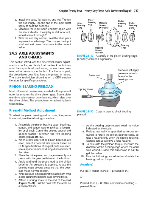
As the bearing cage rotates, read the value7. indicated on the scale.Preload normally is specified as torque re-8. quired to rotate the pinion bearing cage, so take a reading only when the cage is rotating. Starting torque will give a false reading.To calculate the preload torque, measure the 9. diameter of the bearing cage where the cord was wound. Divide this dimension in half to get the radius.10. U se the following procedure to calculate thebearing preload torque:Standard.Pull (lb) 3 radius (inches) 5 preload (lb-in.)orPreload (lb-in.) 3 0.113 (a conversion constant) 5 preload (N .m)Install the yoke, flat washer, and nut. Tighten 6. the nut snugly. Tap the end of the input shaft lightly to seat the bearings.Measure the input shaft endplay again with 7. the dial indicator. If endplay is still incorrect, repeat steps 3 through 7.With the endplay correct, seal the shim pack 8. to prevent lube leakage. Then torque the i nput shaft nut and cover capscrews to the correct value.24.5 A XLE ADJUSTMENTSAND CHECKSThis section introduces the differential carrier adjust-ments, checks, and tests that the truck technician must be capable of performing; some have beenr eferred to previously in the text. For the most part, the procedures described here are general in nature. The truck technician should refer to OEM servicel iterature for specific procedures.PINION BEARING PRELOADMost differential carriers are provided with a press-fit outer bearing on the drive pinion gear. Some older rear drive axles use an outer bearing, which slips over the drive pinion. The procedures for adjusting both types follow.Press-Fit Method AdjustmentTo adjust the pinion bearing preload using the press-fit method, use the following procedure:Assemble the pinion bearing cage, bearings, 1. spacer, and spacer washer (without drive pin-ion or oil seal). Center the bearing spacer and spacer washer between the two bearing cones (Figure 24–49).When a new gear set or pinion bearings are 2. used, select a nominal size spacer based on OEM specifications. If original parts are used, use a spacer removed during disassembly of the drive.Place the drive pinion and cage assembly in a 3. press, with the gear teeth toward the bottom.Apply and hold the press load to the pinion 4. bearing. As pressure is applied, rotate the bearing cage several times so that the bear-ings make normal contact.While pressure is held against the assembly, wind 5. a cord around the bearing cage several times.Attach a spring scale to the end of the cord 6. (Figure 24–50). Pull the cord with the scale ona horizontal line.FIGURE 24–49 Assembly of the pinion bearing cage.(Courtesy of Dana Corporation)FIGURE 24–50 Cage in press to check bearingp reload.Sleeve must applymust be against the outer bearing. If the fit between the yoke or flange splines and drive pinion splines is tight, use a press to install the yoke or flange (Figure 24–51).Temporarily install the drive pinion and cage 4. assembly in the carrier (Figure 24–52). Do not install shims under the bearing cage.Install the bearing cage to the carrier cap-5. screws. Washers are not required at this time. Hand-tighten the capscrews.Fasten a yoke or flange bar to the yoke or 6. flange (Figure 24–53). The bar will hold the drive pinion in position when the nut ist ightened.Metric.Pull (kg) 3 radius (cm) 5 preload (kg-cm) orPreload (kg-cm) 3 0.098 (a conversion constant) 5 preload (N .m)Examples. We can convert the foregoing equa-tions into examples by applying some data to them:Standard7.5 lb 3 3.31 in. 5 24.8 lb-in. (preload) or24.8 lb-in. 3 0.113 5 2.8 N .m (preload)Metric3.4 kg 3 8.4 cm 5 28.6 kg-cm (preload) or28.6 kg-cm 3 0.098 5 2.8 N .m (preload)11. I f necessary, adjust the pinion bearing preloadby changing the pinion bearing spacer. A thicker spacer will decrease preload, whereas a thinner spacer will increase the preload.12. O nce the correct bearing preload has beenestablished, note the spacer size used. Select a spacer 0.001 inch (0.025 mm) larger for use in the final pinion bearing cage assembly pro-cedures. The larger spacer compensates for slight expansion of the bearing, which occurs when pressed on the pinion shank. The trial spacer pack should result in correct pinion bearing preload in three times out of four cases.Y oke Method of AdjustmentTo adjust the pinion bearing preload using the yoke or flange method, proceed as follows:Assemble the complete pinion bearing cage 1. as recommended in the press-fit method.A forward axle pinion is equipped with a heli-2. cal gear. For easier disassembly during bear-ing adjustment procedures, use a dummy yoke (if available) in place of the helical gear.Install the input yoke or flange, nut, and 3.washer on the drive pinion. The yoke or flangeFIGURE 24–51 Using a press to install the yoke orflange to the drive pinion. (Courtesy of Arvin Meritor)FIGURE 24–52 Install the pinion and cage assembly in the carrier housing. (Courtesy of Arvin Meritor)indicated on the torque wrench (see Figure 24–55). Typical value is 50 lb-ft. (68 N .m)m aximum applied to one side gear.If the torque value exceeds the specification, 5. disassemble the differential gears from the case halves.Check the case halves, spider, gears, and 6. thrust washers for the problem that caused the torque value to exceed specifications. Re-pair or replace defective parts as required. Remove any foreign debris.Check/Adjust Pinion Cage Shim PackThis procedure is used to check and adjust the thick-ness of the shim pack used in the pinion bearing cage. Use this procedure if a new drive pinion and crownTighten the nut on the drive pinion to specifi-7. cation, typically 400 to 700 lb-ft. (542 to 950 N .m).Remove the yoke or flange bar.8. Attach a torque wrench to the drive pinion 9. nut. Rotate the drive pinion and read the value indicated on the torque wrench. Preload is correct when the torque required to rotate the pinion bearing cage is from 15 to 35 lb-in. (1.7 to 4.0 N .m).To adjust the pinion bearing preload, disas-10. semble the pinion bearing cage and change the pinion bearing spacer size. A thicker spacer will decrease preload, whereas a thin-ner spacer will increase preload.Differential Rolling ResistanceA check to measure and establish differential rolling resistance follows. To perform this check, a special tool must be made. You can easily make this tool from an old axle shaft that matches the spline size of the differential side gear. Figure 24–54 illustrates the fab-rication specifications for this special tool.To check differential resistance to rotation, use the following procedure:Install soft metal covers over the vise jaws to 1. protect the ring gear (Figure 24–55).Place the differential and crown gear assem-2. bly in the vise.Install the special tool into the differential until 3. the splines of the tool and one side gear are engaged.Attach a torque wrench to the nut of the spe-4. cial tool and rotate the differential gears. As the differential gears rotate, read the valueFIGURE 24–55 Reading the torque value to check the rolling resistance. (Courtesy of Arvin Meritor)FIGURE 24–53 Using a flange bar to hold the drivepinion in position. (Courtesy of Arvin Meritor)FIGURE 24–54 Fabrication details for a tool to checkthe rolling resistance. (Courtesy of Arvin Meritor)If the new pinion cone number is a minus (–), sub-8. tract the number from the standard shim packthickness that was calculated in step 3 or 4.The value calculated in step 7 or 8 is the 9.t hickness of the new shim pack that will bei nstalled. Figure 24–59 illustrates several e xamples of determining shim pack t hickness.Install the drive pinion, bearing cage, and new10. shim pack into the differential carrier.gear set is to be installed, or if the depth of the drive pinion has to be adjusted. You are checking the rolling resistance using a torque wrench.To check/adjust the shim pack thickness (Figure 24–56), do the following:With a micrometer, measure the thickness of 1. the old shim pack removed from under the pinion cage (Figure 24–57). Record the mea-surement for later use.Look at the pinion cone (PC) variation number 2. on the drive pinion being replaced (Figure 24–58). Record this number for later use also.If the old pinion cone number is a plus (+), 3. subtract the number from the old shim pack thickness that was recorded in step 1.If the old pinion cone number is a minus (–), 4. add the number to the old shim thickness that was measured in step 1.The value calculated in step 3 or 4 is the 5.t hickness of the standard shim pack without variation.Look at the PC variation number on the new 6. drive pinion that will be installed. Record the number for later use.If the new pinion cone number is a plus (+), 7. add the number to the standard shim packthickness that was calculated in step 3 or 4.FIGURE 24–56 Drive pinion depth controlled by shimpack thickness. (Courtesy of Arvin Meritor)FIGURE 24–57 Measuring the thickness of the old shim pack. Mike each shim individually then add tocalculate total thickness. (Courtesy of Arvin Meritor)FIGURE 24–58 Location of the pinion cone (PC)v ariation number. (Courtesy of Arvin Meritor)Adjust Differential Bearing PreloadOne of two methods can be used to check and adjust the preload of the differential bearings.Method One.Attach a dial indicator onto the mounting 1. flange of the carrier and adjust the indicator so that the plunger rides on the back surface of the crown ring gear (Figure 24–60).Loosen the bearing adjusting ring that is op-2. posite the ring gear so that a small amount of endplay is indicated on the dial indicator. To turn the adjusting rings, use a T-bar wrench that engages two or more opposite notches in the ring (Figure 24–61).Move the differential and crown gear to the 3. left and right using prybars as you read the dial indicator. Use two prybars that fit be-tween the bearing adjusting rings and the ends of the differential case (Figure 24–62). You also can use two prybars between the differential case or crown gear and the carrier at locations other than those just described. In either case, the prybars must not touch the differential bearings.EXAMPLES:Inchesmm 1.Old Shim Pack Thickness Old PC Number, PC +2Standard Shim Pack Thickness New PC Number, PC +5New Shim Pack Thickness .030.76–.002–.05.028.71+.005+.13.033.842.Old Shim Pack Thickness Old PC Number, PC –2Standard Shim Pack Thickness New PC Number, PC +5New Shim Pack Thickness .030.76+.002+.05.032.81+.005+.13.037.943.Old Shim Pack Thickness Old PC Number, PC +2Standard Shim Pack Thickness New PC Number, PC –5New Shim Pack Thickness .030.76–.002–.05.028.71–.005–.13.023.584.Old Shim Pack Thickness Old PC Number, PC –2Standard Shim Pack Thickness New PC Number, PC –5New Shim Pack Thickness.030.76+.002+.05.032.81–.005–.13.027.68FIGURE 24–59 Determining shim pack thickness.(Courtesy of ArvinMeritor Inc.)FIGURE 24–60 Dial indicator attached to carrier-mounted flange. (Courtesy of Arvin Meritor)FIGURE 24–61 Turning the adjusting ring using aT-bar wrench. (Courtesy of Arvin Meritor)FIGURE 24–62 Using pry bars to adjust play in the crown gear. (Courtesy of Arvin Meritor)Tighten the same bearing adjusting ring4.so that no endplay shows on the diali ndicator.Move the differential and crown gear to the5.left and right as needed. Repeat step 3 untilzero endplay is achieved.Tighten each bearing adjusting ring one6.notch from the zero endplay measured instep 4.Method Two.A second method of checking pre-load is to measure the expansion between the bearing caps after you tighten the adjusting rings. Use the following procedure:Turn both adjusting rings hand tight against1.the differential bearings.Measure the distance X or Y between oppo-2.site surfaces of the bearing caps (Figure24–63A) using a large micrometer of thec orrect size (Figure 24–63B). Make a note ofthe m easurement.Tighten each bearing adjusting ring one3.notch.Measure the distance X or Y again. Compare4.the dimension with the distance X or Y mea-sured in step 2. The difference between thetwo dimensions is the amount that the bear-ing caps have expanded.Example: Measurements of a carrier.Distance X or Y before tightening adjusting rings5 15.315 inches (389.00 mm)Distance X or Y after tightening adjusting rings5 15.324 inches (389.23 mm)15.324 inches minus 15.315 inches5 0.009 inch (0.23 mm) differenceIf the dimension is less than specification, repeat steps 3 and 4 as needed.Crown Gear Runout CheckTo check the runout of the crown/ring gear, do the f ollowing:Attach a dial indicator on the mounting flange1.of the differential carrier (Figure 24–64).Adjust the dial indicator so that the plunger or2.pointer is against the back surface of thecrown gear.FIGURE 24–63 (A) Location of distances measured to check expansion between bearing caps aftert ightening adjusting rings; (B) measuring this distance.(Courtesy of Arvin Meritor)FIGURE 24–64 Checking crown gear runout. (Courtesy of Arvin Meritor)Pinion and Crown Tooth ContactA djustment Correct tooth contact between the pinion and crown gear cannot be overemphasized, because improper tooth contact results in noisy operation and prema-ture failure. The tooth contact pattern consists of the lengthwise bearing (along the tooth of the ring gear) and the profile bearing (up and down the tooth). F igure 24–68 shows crown gear toothn omenclature.Adjust the dial of the indicator to zero.3. Rotate the differential and crown gear when4. reading the dial indicator. The runout of the crown gear must not exceed 0.008 inch (2 mm) (a typical value; refer to the applicable OEM service literature for the specificv alues).If runout of the crown gear exceeds the speci-5. fication, remove the differential and crown gear assembly from the carrier. Check the dif-ferential components, including the carrier, for the problem causing the runout of the gear to exceed specification. Repair or replace defec-tive components.After the components are repaired or re-6. placed, install the differential and crown gear into the carrier.Repeat the preload adjustment of the 7. differential bearings. Then repeat this runout procedure.Check/Adjust Crown Gear BacklashIf the used crown and pinion gear set is installed, ad-just the backlash to the setting that was measured before the carrier was disassembled. If a new gear set is to be installed, adjust backlash to the correct speci-fication for the new gear set.To check and adjust ring gear backlash, do thef ollowing: Attach a dial indicator onto the mounting1. flange of the carrier (see Figure 24–64).Adjust the dial indicator so that the plunger is 2. against the tooth surface at a right angle.Adjust the dial of the indicator to zero, making 3. sure that the plunger is loaded through at least one revolution.Hold the drive pinion in position.4. When reading the dial indicator, rotate the5. crown gear a small amount in both directions against the teeth of the drive pinion (Figure 24–65). If the backlash reading is not within specification (typically ranging from 0.010 to 0.020 inch or 254 to 508 mm), adjust backlash as outlined in steps 6 and 7.Loosen one bearing adjusting ring one notch 6. and then tighten the opposite ring the same amount. Backlash is increased by moving the crown gear away from the drive pinion (Figure 24–66). Backlash is decreased by moving the crown gear toward the drive pin-ion (Figure 24–67).Repeat steps 2 through 5 until the backlash is 7.within specifications.FIGURE 24–65 Check crown gear backlash. ( Courtesy of Arvin Meritor)FIGURE 24–66 Adjustments to increase backlash. (Courtesy of Arvin Meritor)the pattern in an unloaded condition (such as when you are performing this test) will be approximately one-half to two-thirds of the crown gear tooth in most models and ratios.Checking Tooth Contact Pattern on a Used Gear Set. Used gearing will not usually display the square, even contact pattern found in new gear sets. The gear will normally have a pocket at the toe-end of the gear tooth (Figure 24–71) that tails into a contact line along the root of the tooth. The more use a gear has had, the more the line becomes the dominant characteristic of the pattern.Adjusting Tooth Contact Pattern. When dis-assembling, make a drawing of the gear tooth con-tact pattern so that when reassembling it is possible to replicate approximately the same pattern. A cor-rect pattern should be clear of the toe and centers evenly along the face width between the top land and the root. Otherwise, the length and shape of the pattern can be highly variable and are usually con-sidered acceptable—providing the pattern does not run off the tooth at any time. If necessary, adjust the contact pattern by moving the crown gear and drive pinion.Checking Tooth Contact Pattern on a New Gear Set. Paint 12 crown gear teeth with a marking compound (Figure 24–69) and roll the gear to obtain a tooth contact pattern. A correct pattern should be well centered on the crown gear teeth with lengthwise contact clear of the toe (Figure 24–70). The length ofFIGURE 24–67 Adjustments to decrease backlash.(Courtesy of Arvin Meritor)FIGURE 24–68 Crown gear tooth nomenclature.(Courtesy of Dana Corporation)FIGURE 24–69 Application of a marking compoundto check tooth contact. (Courtesy of Dana Corporation)FIGURE 24–70 Correct tooth contact patternfor new gearing. (Courtesy of Dana Corporation)FIGURE 24–71 Correct tooth contact pattern for used gearing. (Courtesy of Dana Corporation)making adjustments, first adjust the pinion and then the backlash. Continue this sequence until the pattern is satisfactory.Thrust Screw AdjustmentFor those differential carriers equipped with a thrust screw, perform the following procedure. (If the carrier assembly does not have a thrust block, proceed to step 4 of this procedure.)Rotate the carrier in the repair stand until the 1. back surface of the crown gear is toward the top.Put the thrust block on the back surface of 2. the ring gear. The thrust block must be in the center between the outer diameter of the gear and the differential case.Rotate the crown gear until the thrust block 3. and hole for the thrust screw, in the carrier, are aligned.Install the jam nut on the thrust screw, one-4. half the distance between both ends (Figure 24–74).Install the thrust screw into the carrier until the 5. screw stops against the crown gear or thrust block.Loosen the thrust screw one-half turn, or 180 6. degrees.Tighten the jam nut to the correct torque value 7. against the carrier (typical values range from 150 to 295 lb-ft. or 200 to 400 N .m) (Figure 24–75).Axle TrackingAxle tracking can be measured using the older tram bar method or electronic alignment equipment. The procedures for setting axle alignment and tracking areexplained in Chapter 25.FIGURE 24–72 Two incorrect patterns when adjusting pinion position. (Courtesy of Dana Corporation)Crown gear position controls the backlash setting. This adjustment also moves the contact pattern along the face width of the gear tooth (Figure 24–72). Pinion position is determined by the size of the pinion bear-ing cage shim pack. It controls contact on the tooth depth of the gear tooth (Figure 24–73).These adjustments are interrelated. As a result, they must be considered together even though thepattern is altered by two distinct operations. WhenFIGURE 24–73 Two incorrect patterns when adjusting backlash. (Courtesy of Dana Corporation)• Most differential carriers are replaced as rebuilt/exchange units, so the role of the technician is, more often than not, to diagnose the problem and then, if necessary, to replace the defective assembly as a unit.• The technician who has disassembled and reas-sembled differential carriers should find trouble-shooting procedures easier to follow.• Follow the OEM procedure when disassem-bling differential carriers. Taking a few mo-ments to measure shim packs and gear tooth contact patterns on disassembly can save considerable time when reassembling thec arrier.• A crown and pinion gear set often can ber eused when rebuilding a differential carrier. Make sure that you inspect it properly ond isassembly.• Crown and pinion gear sets are always replaced as a matched pair during a rebuild.• When setting crown and pinion backlash, it is increased by moving the crown gear away from the drive pinion and decreased by moving the crown gear toward the drive pinion.• Adhering to OEM-recommended lubrication schedules is the key to ensuring the longest service life from both drive and dead axles.• Knowing the correct procedure to check lubricant level is essential. The level is correct when lubri-cant is exactly level with the bottom of the fill hole.• Because most OEMs approve of the use of syn-thetic lubricants in final drive carriers, lubrication drain schedules have been greatly increased in recent years. Drain schedules are determined by the actual lubricant used and the type of appli-cation to which the vehicle is subjected.• Servicing of axles on heavy-duty trucks consists of routine inspection, lubrication, cleaning, and, when required, troubleshooting and component overhaul.• Failure analysis is required to prevent recurrent failures.• Drive axle carrier components usually fail for one of the following reasons: Shock load Fatigue Spinout Lubrication problemsNormal wearFIGURE 24–74 Installing the jam nut on the thrust screw. (Courtesy of Arvin Meritor)FIGURE 24–75 Tighten the jam nut to the correct torque value. (Courtesy of Arvin Meritor)SUMMARY。
Kd1080型载货汽车后桥总成设计摘要本设计为中型载货汽车的后桥总成设计。
在本设计中后桥为驱动桥,是汽车传动系主要总成之一,具有承载车身和驱动汽车的功用。
后桥设计应满足汽车动力性,经济性的要求,并符合汽车运动学规律。
根据本车的各项具体参数,经过必要的论证分析,确定了本次所设计的驱动桥的结构方案。
后桥采用非断开式驱动桥壳,单级螺旋锥齿轮主减速器,对称式圆锥行星齿轮差速器,半浮式支承半轴,驱动车轮为四个,后桥采用轴承为圆锥滚子轴承。
在已知主传动比的情况下,选择准螺旋锥齿轮主减速器齿轮的型式,目的是为了降低成本,并且工作平稳,噪声小。
对称式圆锥行星齿轮差速器结构简单,使用可靠。
半浮式半轴结构简单,所受载荷较大。
圆锥滚子轴承承载能力强,且有利于主减速器齿轮副调整。
全套图纸,加153893706在说明书的计算部分,说明了主要参数选择的依据,对主减速器,差速器,半轴和驱动桥壳进行了尺寸和强度计算。
此外,还计算了主减速器支撑轴承的寿命。
本文提供了关于以上计算的详细计算依据、步骤和计算数据。
关键词:驱动桥,半轴齿轮,差速器,半轴DESIGN OF REAR AXLE FOR MEDIUM GOODSVEHICLEABSTRACTThe aim of this project is to design the rear axle for the medium goods vehicle. The rear axle acts as the driving axle in this project., which is used to bear the frame and drive the car. The design of the rear axle should meet with the requirement of the performance of power and economic, and the same time, it must be accord to the principle of the mechenics of vehicle.According the specific parameters of the driving system and necessary reasoning, this rear axle conclude the integrated driving axle housing, the main drive of single spiral bevel gear ,the differential with taper planetary gear, the half axle and so on. There are four driving wheel and the bearings that the rear axle used are both taper roller bearings. With the provision of the drive ratio, the spiral bevel gear is selected in this design, which aimed to minimize the cost and make little noise. The differential with the symmetric taper planetary has a relatively simple structure, and it is reliable.The calculation section of this paper is mainly concerning about the physical dimension of the gear of the main drive and the differential,the driving axle, and the strength proofread of it. In addition, the strength proofread of it. In addition, the life of the bearing of the main drive is also calculated in this of computations basis,the step and the estimated data for these project and advanced in paper.KEY WORDS: Driving axle, Hypoid gear, Differential, Axle shaft目录前言 (1)第一章驱动桥的结构方案分析 (2)第二章主减速器的设计 (4)§主减速器的结构形式和选择 (4)§ (4)§ (5)§ (8)§.......................1 1 第三章差速器的设计 (26)§........................2 6 §..............2 6 第四章驱动车轮的传动装置 . (32)§ (32)§ (32)第五章驱动桥桥壳 (36)第六章结论......................... .... . . (41)参考文献 (42)致谢 (43)前言汽车的驱动桥位于传动系的末端,其基本功用是增大由传动轴或直接由变速器传来的转矩,将转矩分配给左、右驱动车轮,并使左、右驱动车轮具有汽车行驶运动学所要求的差速功能;同时,驱动桥还要承受作用于路面和车架或承载式车身之间的铅垂力、纵向力和横向力及其力矩。
越野车驱动桥设计开题报告1. 引言越野车作为一种特殊用途车辆,需要具备强大的越野能力和驱动系统。
驱动桥作为越野车的核心部件之一,对整车的牵引力和操控性起着重要作用。
本报告将介绍越野车驱动桥的设计方案及其相关问题。
2. 背景传统的驱动桥设计主要适用于普通道路驾驶,无法满足越野车在崎岖地形和困难道路上的需求。
因此,设计一种适应越野环境的驱动桥显得尤为重要。
3. 目标本次开题研究的目标是设计一种越野车驱动桥,具备以下特点:- 高承载能力:驱动桥需要能够承受大马力的输出并具备足够的强度和耐久性。
- 良好的通过性:驱动桥应能适应各类恶劣地形条件,如泥泞、陡坡、沙漠等。
- 可调性能:驱动桥需要具备可调节的差速装置和扭矩分配机构,以适应不同道路状况和驾驶习惯。
-简单可靠:驱动桥应设计简单,易于维护和修理,并具备较高的可靠性。
4. 方法本次设计将采用以下步骤: 1. 确定越野车的使用情况和运动学要求,包括最大扭矩、最大速度、最大通过角度等。
2. 分析越野车的驱动系统特点和运动学模型,确定驱动桥的基本设计参数。
3. 选择合适的材料和制造工艺,确保驱动桥具备足够的强度和耐久性。
4. 设计差速装置和扭矩分配机构,以实现优良的操控性能和通过性能。
5. 进行系统集成和优化设计,确保各个部件协同工作并满足整车的要求。
6. 进行仿真和实验验证,评估驱动桥的性能和可靠性。
5. 期望成果通过本次设计,我们期望获得以下成果: 1. 完整的越野车驱动桥设计方案,包括各个部件的参数和功能要求。
2. 详细的制造工艺流程和工艺参数,以确保驱动桥的制造质量。
3. 仿真和实验结果,评估驱动桥的性能和可靠性。
4. 针对发现的问题和改进的方案,提出进一步的研究和改进计划。
6. 计划安排本次研究计划按以下时间安排进行: - 第一周:调研相关文献,了解越野车驱动桥的发展现状和问题。
- 第二周:确定越野车使用情况和运动学要求,分析驱动系统特点。
断开式驱动桥名词解释
断开式驱动桥是一种在汽车、摩托车等轮式车辆上进行驱动系统的设计技术,也被称为桥式驱动系统或悬挂系统。
与传统的驱动桥相比,断开式驱动桥在设计和制造过程中具有一些独特的特点。
断开式驱动桥的主要特点是将驱动桥分为两个部分,一部分是桥壳,另一部分是桥板。
桥壳通常由铝合金或复合材料制成,而桥板则是由钢或铝合金等金属材料制成。
在桥壳和桥板之间,设有一种特殊的橡胶垫,这个垫可以吸收车辆在行驶过程中产生的震动和颠簸,提高车辆的舒适性和稳定性。
断开式驱动桥的工作原理是通过两个驱动桥壳之间的桥板连接来实现驱动系统的连接。
当车辆在行驶时,驱动桥壳和桥板之间的橡胶垫会吸收车辆的重量和震动,并将这些能量转化为热能,从而减小驱动桥的磨损。
同时,断开式驱动桥还可以提高车辆的悬挂系统和驱动系统的响应速度,使车辆在行驶过程中更加平稳和舒适。
断开式驱动桥在汽车设计领域得到了广泛应用,特别是在赛车和高性能车辆上。
断开式驱动桥的制造成本较高,因此需要对制造过程进行更加精细的控制和优化,以确保车辆的质量和质量稳定性。
断开式驱动桥的优点是具有更好的舒适性和稳定性,同时可以降低驱动桥的磨损和寿命。
但是,在制造过程中需要更高的技术水平和精度,因此需要专业的制造公司来完成。
附录A 英文文献Drive AxleAll vehicles have some type of drive axle/differential assembly incorporated into the driveline. Whether it is front, rear or four wheel drive, differentials are necessary for the smooth application of engine power to the road.PowerflowThe drive axle must transmit power through a 90°angle. The flow of power in conventional front engine/rear wheel drive vehicles moves from the engine to the drive axle in approximately a straight line. However, at the drive axle, the power must be turned at right angles (from the line of the driveshaft) and directed to the drive wheels.This is accomplished by a pinion drive gear, which turns a circular ring gear. The ring gear is attached to a differential housing, containing a set of smaller gears that are splined to the inner end of each axle shaft. As the housing is rotated, the internal differential gears turn the axle shafts, which are also attached to the drive wheels.Rear-wheel driveRear-wheel-drive vehicles are mostly trucks, very large sedans and many sports car and coupe models. The typical rear wheel drive vehicle uses a front mounted engine and transmission assemblies with a driveshaft coupling the transmission to the rear drive axle. Drive in through the layout of the bridge, the bridge drive shaft arranged vertically in the same vertical plane, and not the drive axle shaft, respectively, in their own sub-actuator with a direct connection, but the actuator is located at the front or the back of the adjacent shaft of the two bridges is arranged in series. Vehicle before and after the two ends of the driving force of the drive axle, is the sub-actuator and the transmission through the middle of the bridge. The advantage is not only a reduction of the number of drive shaft, and raise the driving axle of the common parts of each other, and to simplify the structure, reduces the volume and quality.Fig 2 Rear-wheel-drive axleSome vehicles do not follow this typical example. Such as the older Porsche or Volkswagen vehicles which were rear engine, rear drive. These vehicles use a rear mounted transaxle with halfshafts connected to the drive wheels. Also, some vehicles were produced with a front engine, rear transaxle setup with a driveshaft connecting the engine to the transaxle, and halfshafts linking the transaxle to the drive wheels.Differential operationIn order to remove the wheel around in the kinematics due to the lack of co-ordination about the wheel diameter arising from a different or the same rolling radius of wheel travel required, inter-wheel motor vehicles are equipped with about differential, the latter to ensure that the car driver Bridge on both sides of the wheel when in range with a trip to the characteristics of rotating at different speeds to meet the requirements of the vehicle kinematics.Fig 3 Principle of differentialThe accompanying illustration has been provided to help understand how this occurs.1.The drive pinion, which is turned by the driveshaft, turns the ring gear.2.The ring gear, which is attached to the differential case, turns the case.3.The pinion shaft, located in a bore in the differential case, is at right angles to the axle shafts and turns with the case.4.The differential pinion (drive) gears are mounted on the pinion shaft and rotate with the shaft .5.Differential side gears (driven gears) are meshed with the pinion gears and turn with the differential housing and ring gear as a unit.6.The side gears are splined to the inner ends of the axle shafts and rotate the shafts as the housing turns.7.When both wheels have equal traction, the pinion gears do not rotate on the pinion shaft, since the input force of the pinion gears is divided equally between the two side gears.8.When it is necessary to turn a corner, the differential gearing becomes effective and allows the axle shafts to rotate at different speeds .Open-wheel differential on each general use the same amount of torque. To determine the size of the wheel torque to bear two factors: equipment and friction. In dry conditions, when a lot of friction, the wheel bearing torque by engine size and gear restrictions are hours in the friction (such as driving on ice), is restricted to a maximum torque, so that vehicles will not spin round. So even if the car can produce more torque, but also need to have sufficient traction to transfer torque to the ground. If you increase the throttle after the wheels slip, it will only make the wheels spin faster.Fig 4 Conventional differentialLimited-slip and locking differential operationFig 5 Limited-slip differentialDifferential settlement of a car in the uneven road surface and steering wheel-driven speed at about the different requirements; but is followed by the existence of differential in the side car wheel skid can not be effective when the power transmission, that is, the wheelslip can not produce the driving force, rather than spin the wheel and does not have enough torque. Good non-slip differential settlement of the car wheels skid on the side of the power transmission when the issue, that is, locking differential, so that no longer serve a useful differential right and left sides of the wheel can be the same torque.Limited-slip and locking differential operation can be divided into two major categories:(1) mandatory locking type in ordinary differential locking enforcement agencies to increase, when the side of the wheel skid occurs, the driver can be electric, pneumatic or mechanical means to manipulate the locking body meshing sets of DIP Shell will be with the axle differential lock into one, thus the temporary loss of differential role. Relatively simple structure in this way, but it must be operated by the driver, and good roads to stop locking and restore the role of differential.(2) self-locking differential installed in the oil viscosity or friction clutch coupling, when the side of the wheel skid occurs when both sides of the axle speed difference there, coupling or clutch friction resistance on the automatic, to make certain the other side of the wheel drive torque and the car continued to travel. When there is no speed difference on both sides of the wheel, the frictional resistance disappeared, the role of automatic restoration of differentials. More complicated structure in this way, but do not require drivers to operate. Has been increasingly applied in the car. About non-slip differential, not only used for the differential between the wheels, but also for all-wheel drive vehicle inter-axle differential/.Gear ratioThe drive axle of a vehicle is said to have a certain axle ratio. This number (usually a whole number and a decimal fraction) is actually a comparison of the number of gear teeth on the ring gear and the pinion gear. For example, a 4.11 rear means that theoretically, there are 4.11 teeth on the ring gear for each tooth on the pinion gear or, put another way, the driveshaft must turn 4.11 times to turn the wheels once. The role of the final drive is to reduce the speed from the drive shaft, thereby increasing the torque. Lord of the reduction ratio reducer, a driving force for car performance and fuel economy have a greater impact. In general, the more reduction ratio the greater the acceleration and climbing ability, and relatively poor fuel economy. However, if it is too large, it can not play the full power of the engine to achieve the proper speed. The main reduction ratio is more Smaller ,the speed is higher, fuel economy is better, but the acceleration and climbing ability will be poor.附录B 文献翻译驱动桥所有的汽车都装有不同类型的驱动桥和差速器来驱动汽车行驶。
附录附录AHeavy Off-Road Vehicle Drive Axle Of BreakingThe important thing is, in the great assembly at the end of the transmission. Its basic function is increased by the transmission shaft or directly by the torque, came to the torque distribution to left and right drive wheels, and make the right and left wheel drive car has required the kinematics differential function, While carrying the spring load and the car wheel, the frame of the body through suspension or integral to plumb-lines, longitudinal and transverse force and moment force, Also the biggest transfer transmission torque, still under the bridge housing reaction torque.Drive structure and driving wheel is closely related to the suspension structure. When driving wheel using an independent suspension, using the broken open axles, When driving wheels adopt independent suspension, match with breaking drive axles, independent suspension. Look from exterior, independent suspension axles connectionless left and right of the whole bridge rigid driving wheel, shell is bridge housing, and other relative movement between. This bridge is installed in the middle frame or integral car transmission and driving wheel transmission device and part of the quality of the automobile suspension with belong to the quality and the side of the drive wheels with independent suspension of elastic component and frame or weak connection for cars. Therefore, one on either side of the drive wheels can independently, relative to the frame or cars do, swing, left, and right shaft corresponding requirements and their corresponding shell makes the corresponding swing. Cars drive by breaking the suspension, and the quality of small and independent suspension matching, can make the driving wheels of various earthing and adaptability, good roads that can greatly reduce the cars in the rough road impact and vibration during the body decreases wheel and axle tilt, the dynamic loads of vehicle, improve and enhance average speed, Reduce the damage, improve its components reliability and prolong its service life.Based on the development of China's heavy independent suspension of six x 6 cross-country car cut off from the drive axles, for example, is insufficient, the development technology independent suspension drive axle of necessity and independent suspensiondrive axle of structural principle in aspects of heavy off-road vehicle drive with independent suspension of this development.1 Domestic independent suspension drive technology situationAt present domestic independent suspension axles in cars, light off-road vehicle and JN252 8 x 8, etc ZhongDunWei military car has been applied and independent suspension heavy off-road vehicle axles technology is basically blank, Foreign independent suspension heavy off-road vehicle axles technology also only by American company, belarus, Minsk Sisu, Finland has TIMONEY company and Korea etc, and application scope of military and civilian limitations in some special models.2 Develop independent suspension drive axle of necessityIn recent years, with independent suspension off-road vehicle market demand more and more widely. Restrict independent suspension off-road vehicle development is one of the key factors, thus breaking drive axles of the necessity of developing broken off.2.1Military car development needsCurrently our extensive use of grade 6 x 6 type 7t SX2190 models is shaanxi automobile manufacturing factory using STEYR technology development of new generation rover, has good performance, and strong adaptability, good performance advantages over the past 20 years for national defense construction made great contribution. The truck with 8 x 8 upward-leading continuous casting.the JN2270 15t and capability of type x 8 August JN2300 type, the successful development of China's second DaiJun car development was at an end. In order to adapt to the needs of modern war, the third DaiJun car development was put on the agenda. Article DaiJun car features for independent suspension of high performance of motor vehicles. As its core technology is one of the big Hollywood drive shaft cut off, domestic blank, basic is dependence on imports, if do not accord with national also does not conform to the military.2.2The basic needs of national constructionFor many years, our national economy is developing rapidly, and infrastructure investment growth, hydroelectric power, oil field, mine, coal and other industries such as fire like tea. The industry is inseparable from the high quality, the high performance of transport vehicles, independent suspension off-road vehicle is among the top. However, these vehicles almost entirely on imports, spent a great deal of foreign exchange. To develop a replacement model is of great significance to meet the market demand.3 Independent suspension structure theory. Drive axle ofChina's heavy automobile group company with development and production status, independent development drive axle of the independent suspension 6 x 6 cross-country car drive shaft cut off big Hollywood. According to 6 x 6 independent suspension chassis design requirements, in this model adopted high transmission fault type axles. The first thing is to cut off to drive, high of double bridge for breaking through the medium-sized Bridges, rear axles turn for breaking steering of high axles. Three bridge are installed with gas control differential between the wheel lock differential, medium-sized Bridges across the bridge box installed with gas control differential between the lock shaft differential. Main reducer ratio for 1 2023, gear ratio for 4. 26 (belt wheel side filling put gas system, ABS), the total ratio 7.016, The medium-sized Bridges for Φ 180 input end tooth flanges, output for Φ 165 end flange, rear axle gears before the input for Φ 165 end tooth flange, Each shaft axis for jose 13t. This design is mainly in steyr drive technology based on the development and design, design thoughts and 6 x is 6, 8 x 8, 10 December 10, military USES 10 series assemblies, reduce the new design of special parts. 8 x 8 middle bridge, 10 assembly, 10, and 12 million spxillion structure types are similar. The new design two broken open bridge, front axle shell adopts the breakthrough in the shell, type of bridge, using the same type of the rear axle housing learnings. On the basis of that, left, right, two kinds of half axle and cover and spline set assembly, and on the reduction and bridge box shell and the local improvement. High technology to drive the corresponding design. Before using high to drive axle of bridge structure, thus make the box with the same drive axle of center distance of the bridge, i.e. input than the original structure of flange steyr 100mm up front axle and bridge, can satisfy the same height flange vehicle transmission Angle to decorate the small request. Before turning mainly by high drive axles, before breaking casting bridge in the middle of the disc brake, using the shell with the filling of the deflated wheelhub ball cage patterned assembly, universal shaft coupling assembly etc. And now the thing turn compared with has the following characteristics: ①Using steel bridge housing, good rigidity, high strength.②Using steyr mature main reducer and axle box of bridge structure of the existing technology (without prior to drive axle box structure), improve cross the bridge reliability.③Using the ball cage patterned double gimbal couplings, can make the centerline of ball cage with to the center of the kingpin always in line with the wheels, reduce sliding wear.4 conclusionWith independent suspension car of rapid development, large-tonnage breaking drive axle of development of necessity and urgency. It not only can greatly improve the car ride and mobility, also for automobile driving performance such as power, economy, and has a direct impact on the stability, etc. Both can satisfy the military modernization needs, also can meet the needs of the development of national economy, therefore has the important practical significance.附录B重型越野汽车断开式驱动桥的研发驱动桥是汽车的重要大总成,处于传动系的末端。