10公斤真空熔炼炉技术方案英文版
- 格式:pdf
- 大小:599.12 KB
- 文档页数:9
真空精炼炉工艺技术说明(VOD设备)1.1设备的功能、用途和可靠性VOD型真空精炼设备是目前世界上使用最广泛的炉外精炼设备之一。
它具有设备简单、投资少、成本低、精炼钢种多、质量高、操作方便等诸多优点,因此成为特钢厂必备的精炼手段。
VOD-40t钢包精炼炉具有真空脱气、吹氩搅拌、吹氧脱碳、非真空测温取样等多种功能。
可以精炼轴承钢、合金结构钢、弹簧钢、优质碳素钢、超低碳不锈钢等。
由于它具有极强的真空脱气能力,因此可保证钢种的氢、氧、氮含量达到最低水平,并精确调整钢水成分,使夹杂物充分上浮,而有效提高钢的纯洁度,正因为它精炼的钢种多、质量高,可以为用户更灵活的适应市场竞争的需要,及时精炼出市场需要的钢种,从而增加企业的经济效益。
1.2方案布置本套VOD-40t钢包精炼炉总体布置初步采用罐体半高架、固定不动,罐盖移动形式。
1.3 设备先进性VOD-40t钢包精炼炉当不作吹氧操作时,VOD炉可完全实现VD炉操作功能。
冶炼时罐体和真空泵相连,其间通过主截止阀,可实现罐体与真空泵的启闭,并可在钢包吊入罐体之前,先对真空管道进行予抽,这样可以充分利用真空泵,缩短罐体的抽气时间和减少温降,使VOD炉和初炼炉、LF、浇铸相匹配,达到最佳效果。
该设备包括:一个真空罐系统、一个真空罐盖系统,一个罐盖升降及罐盖车系统,吹氧装置,真空加料装置,一套真空泵系统,一套连接罐与真空泵的真空管道系统,液压系统,吹氧系统,吹氩系统,压缩空气系统,冷却水系统,TV摄像装置,一套电气控制及仪表监测设备系统。
在真空泵的造型和设计,罐盖的设计与密封性,吹氧装置的设计与密封以及全套计算机控制系统等方面,皆按目前世界上最先进的结构进行优化设计,以保证本设备的先进性,合理性,通用性。
设备特点:(1)、真空罐接受要处理的钢包,吊车将钢包置于真空罐中后,人工连接上氩气管,罐为焊接结构,并设有钢包导向结构,以方便起吊钢包。
具有耐火材料的内衬以防止热应力。
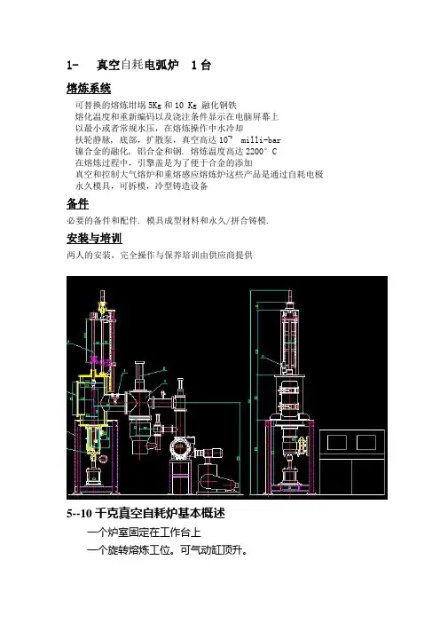
1- 真空自耗电弧炉 1台熔炼系统可替换的熔炼坩埚5Kg和10 Kg 融化钢铁熔化温度和重新编码以及浇注条件显示在电脑屏幕上以最小或者常规水压,在熔炼操作中水冷却扶轮静脉, 底部,扩散泵,真空高达10-8 milli-bar镍合金的融化, 铝合金和钢. 熔炼温度高达2200°C在熔炼过程中,引擎盖是为了便于合金的添加真空和控制大气熔炉和重熔感应熔炼炉这些产品是通过自耗电极永久模具,可拆模,冷型铸造设备备件必要的备件和配件. 模具成型材料和永久/拼合铸模.安装与培训两人的安装,完全操作与保养培训由供应商提供5--10千克真空自耗炉基本概述一个炉室固定在工作台上一个旋转熔炼工位。
可气动缸顶升。
一个KTZJ300.600油增压泵真空系统一个2000安熔炼电源电源满足熔炼4公斤钛及钛合金锭,5.5公斤锆及锆合金锭,7公斤铁及铁合金锭的需要。
环境要求:提供厂房:梁下4000。
设备电源供电电压为:3 相4线AC 380V±7%土木基础施工。
地平处理混凝土浇注厚度大于200mm采购方配合试车工作电网频率:50Hz±1%压缩空气:压力0.6MP a(如有需要)惰性气体(氩气)气体压力:0.4~0.8 MPa(工业冷水机)提供的循环冷却水:进水温度2℃-20℃,进水压力0.25-0.3Mpa,流量8m3/h应急水:压力:0.2-0.3MP a,(由发电机带动冷水机)海绵钛电极密度:3.3 g/cm3(最小)、钛锭4.5海绵锆电极密度:4.7 g/cm3(最小)、锆锭6.5基本技术参数最大熔化重量:≥5.5Kg锆及锆合金(密度6.5g/cm3)海绵钛电极密度:3.4kg/dm3最大熔炼电流:2000A电极杆最大行程:750mm下炉室升降行程: 100mm开路电压:68V工作电压:20-45V真空系统:一台ZL300油增压泵+一台 ZJ-600罗茨泵+一台2H-70滑阀泵泵电极升降速度:0~280mm/min,无级快速速度:500 mm/min极限真空度:≤7×10-2Pa工作真空度: 10-0.67Pa升压率:≤0.1Pa/min)抽空时间从大气压达到0.1Pa ,≤15分钟。

STEEL SDN. BHD《IMP1#Blast Furnace Stoppage Proposal》Prepared by: Yu Yu FeVerified by: ZheRu, Che We FenApprovedby: Wan She HuIMP7/10/20151. OrganizationCommander: ZhDeputy Commander: Chen W, Woo Wing Nan, and Wang Tan Member: Chia Kay Kiat,YuFeng, Wu Shi, Zha Tie, Li Gu Mi, Liu Qing Jiang, Yang Yu Fe, Su We, Wan Ju We, Guo We Zho, Liu Hai Qing Gao X Do, Wan Zh, Re Xia M, Wa Ha Cu, Gu Yo Ga, Ca Mi Ze, Yan Su Li, To Zhi Ga.2. The shutdown time: 17 October 2015 (Estimated)3. The shutdown method: lowering charge level, or lowering stock line4. Shutdown Requirements1.Ensure the personnel safety, equipment, Co gas,operation of shutdown process to realize safe and smooth shutdown;2.Control of water and air flow, control the furnacetemperature,tapping clean lowering stock line till tuyereheight area, to shorten the process period.5. Preparations for the shutdown1.Ensure a stable material, arrange short positions for eachsilo, fully empty material and coke bunker before blow off.(Responsible person: Yuan Yu Feng, Li Guang Ming, Wang Hai Cun)2.Two days before the shutdown, stop using lump ore,make sure 2 flow of Co gas is proper distribute the edges,use fluorite cleaning BF walls, reducing coke burden andthe temperature control0.6-0.8%, Basicity of slagcontrolR2=1.00±0.05But hearth temperature stabilitymust be guaranteed. (Responsible person: Li Guang Ming)3. 2 Days before shutdown, increase the taphole angle (13 °),and let the tapping flow with suitable rate.(Responsibility people Zh, Li, Liu )4.Enhance BF cooling systemcheckup before the shutdown,especially the tuyere, andslag area. Promptly replaced iffinding leaking, such as cooling wall leaking should beshut down immediately, strengthening the external water.(Responsible person: Rn)5.BF Top water sprays hose and sprays water methods,install 4 spray tube. Pipes according to requirement, with diameters 32mm pipe, long 4000mm, close to the wall1000mm-stinging, with the remainder open diameter3mm eye, 3 rows (60°), Interval 60mm, furnace end-smashing tips welded shut, and testing ahead.(Responsible person: Zhain)6.Pre-readyBF top water devices, control water valvesinstalled on the air platform region, four-way pipe double valve control, all water pressure water pressure not lessthan 0.90MPa, there is enough water, install a pressuregauge on each of the four pipe and flow meter.(Responsible person: Zhanin, and Li, and Gung)7.The temporary stock Rod installation projects (need to beable to reach 16m).(Responsible person: Zhaowei, and Wan, and Chai e)8.Check the lighting installed in every platform.(Responsible person: Che)9.During Lowering stock line period , all participants arerequired to become familiar with the process as a whole, the Division of responsibilities clearly, in particular water, air patrol, temperature detection focus must be clearlyresponsible and must advance the associated exercisesand simulations to ensure implementation without anyaccidents.(Responsible person: Li, anxiang)10.Enhancing each equipment inspection and maintenanceof equipment, reduce or eliminate risk caused byequipment failure to blow off.(Responsible person: Zhang Tiessfully)6.Blow off work (predicted)1.Assuming10-12 hours blow off (for reference only).2.Stopping the use of materials and time schedule.IMP calculated the blow off material, shut down material and covering coke:∙Coke 5500kg,9 batch; adds covered face, empty stock line 7~8M to blow off,∙Blow off time 7:00pm start blow on (and take charge of blow off material determined by the 1# blastfurnace based on speed.(Responsible person: Lduty)3.Pre blow offstop charging material, emptied all bunker,and emptied all the weighing Hopper, Concentratehopper.(Responsible person: Yuan YuCun)4.Removing grease and insulating material around the BFtop, stop BF top lubrication oil; to prevent BF top caught fire during lowered stock line process.(Responsible person: Yaiang)5.Inspection of instruments, on top of thermocouples,pressure gauges and display instrument forcomprehensive proof, including temperature anddirection, in order to ensure accurate temperature during the empty stock line. (Responsible person: Chae)6.The installation of water pipes and adjusted correctly.(Responsible person: Zhannmin)7.Install soft sounding rod and proofread zero installation,adjusted normal.(Responsible person: Zha Waaicun)8.Inspect examination of cooling equipment; ensure there isno leaking in BFduring lowering stock line process.(Responsible person: Rein)9.Deduster collector and the effective partition of blastfurnace (sand), connected with the atmosphere, close the dust collector manhole and N2, a gas pipeline shut thevalve. (Responsible person: Wag)10.Other safety precautions works:1)Blast furnace bleeding valve removed after pre-blow off (Res Li)2)associated company coal of stakeholders,monitoring personnel to the scene, pull up asecurity cordon, contact fire trucks, ambulanceson standby(Responsible person: Wan)3)Blast furnace chutes removed, lower sealinginstall blind flange.(Responsible person: Zhai Cun)7.Lowering stock line operation1.Lowering lines process personalarrangement by theproduction section and the 1# blast furnace siteorganization, equipment, Baowei, co2 gas section.2.During lowering stock line period during productionsection, safetysectionmust monitoring site safety,checking, and validation work.3.Spray Water operations:1.Put in nitrogen into bf top during lowering stock lineprocess.2.Pick up gas sample every 30 minutes duringlowering stock line process for testing h2, and CO, o2,and CO2 content.3.Controls the atomizing water 1st valve opening of 80%(keep open), the 2nd valve according to thetemperature control of water by the personresponsible for the operation.(Responsible Person: Shift in charge)4.Open atomized water before spray water, accordingto bf top temperature spray water, shower valveoperation operated by “Ren Xianmin”.5.Operation strictly according to the temperaturecontrol requirements, such as full temperatureexceeded the maximum limit, timely wind reductionin the furnace. (Shift in charge)4.Temperature control during lowering chargelevel:250℃~400℃,mainly by adjusting the top water andair volume control.5.BF Top water is the key to stability, Water supply must bestable to prevent vapor explosions cause the liningcollapsed, especially to eliminate risk top temperature is less than100℃. Small amount of water in the early, and gradually increase, whileaccording to the temperature fluctuation trend, slow adjustment corresponding to the point of water in advance. The toptemperature300cprogressively decreased; reduce water points in advance, and vice versa. As the line continues to reduce, air flow will automaticallyincrease when water alone cannot control the temperature, must reduce air flow control, reduced air flow in order to reduce windpressure10~20kPa/.6.Blow on after pre-blow off, if the stock line is above thefurnace body, you can control the air flow in theair80~90%about(1500×90%=1350m3/h) 。
真空感应熔炼炉用户手册联系电话目录1前言 3 2真空感应熔炼炉电源 4 3真空感应熔炼炉结构 6 4真空感应熔炼炉的操作说明12 5真空感应熔炼炉的保养15 6真空感应熔炼炉的日常维护20共26页真空感应熔炼炉是生产高品位高纯、精密合金材料、精密铸件的有效装备。
真空感应冶炼是特种冶金中最最常用的一种冶炼工艺。
真空感应冶炼炉在实验室,机械厂,冶金厂,材料厂,应用非常广泛。
从几人、十几人的小工厂到几百几千人的中型大型厂都能见到真空感应冶炼炉。
真空感应冶炼炉一般除实验室冶炼外多数和特种铸造工艺联系在一起。
有先进的工艺才能最大限度的发挥真空该应熔炼炉的作用。
真空感应熔炼炉是生产高附加值合金铸件的常用设备。
真空感应冶炼是较复杂的一种材料加工技术,它需要多方面的理论知识,如冶金学,金属凝固学,机械学,材料学和无机化学等,更需要在实践中总结出各种经验,这样才能不断提高生产合金铸件的成品率及质量。
鉴此我们公司对真空感应冶炼炉做以简单的介绍,供共同提高发展。
由于本公司人员学识有限,文中不妥处在所难免敬请批评指正。
作者:何晓军修改日期;2015年10月一真空感应熔炼炉电源1 集成化变频装置概述集成化变频电源是采用本公司先进的SCR控制集成真空中频变频电路板配合整流,滤波,逆变,中频,变压,中频电容而成的电源装置。
本装置可以广泛应用于金属熔炼等感应加热领域,装置将50HZ的交流电经过三相全控整流,滤波后逆变为1800HZ---2500HZ的单相直流电,再经过电容和变压输出。
本装置为水冷却电源。
本装置按照ZBK46001技术条件生产。
2 使用环境用户使用本装置需要具备以下条件2.1环境温度0---40摄氏度2.2 环境相对湿度不大于85%(相当于20摄氏度环境温度)2.3无导电和以爆炸的尘埃,没有腐蚀金属和损坏绝缘的气体和蒸汽的场所。
2.4 本装置应直立安装在无剧烈震动冲击,无其他强大电磁干扰的场所。
2.5 电网为正弦波,谐波失真不大于+-5%,电压持续波动范围不得超过+-10%,三相电压各相之间不平衡度小于+-5%。
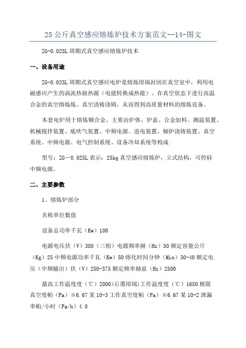
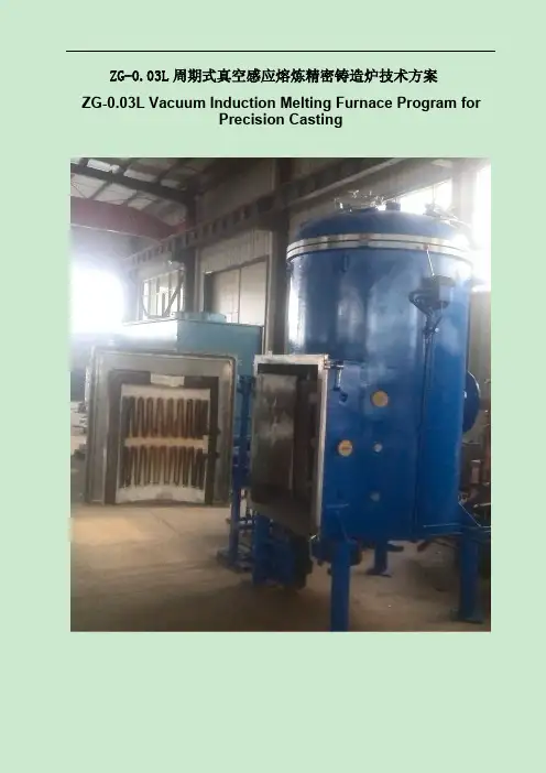
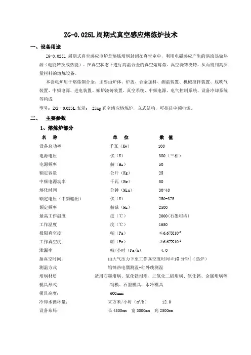
25公斤真空感应熔炼炉技术方案范文--14-图文ZG-0.025L周期式真空感应熔炼炉技术一、设备用途ZG-0.025L周期式真空感应电炉是熔炼坩埚封闭在真空室中,利用电磁感应产生的涡流热做热源(电能转换成热能)。
在真空状态下进行高温合金的真空熔炼炼、真空浇铸浇铸,从而得到高质量材料的熔炼设备。
本套电炉用于熔炼铜合金。
主要由炉体、炉盖、合金加料、测温装置、机械搅拌装置、底吹气装置、中频电源、进电装置、倾炉浇铸装置、真空系统、中频电源、电气控制系统、设备冷却系统等构成型号:ZG-0.025L表示:25kg真空感应熔炼炉,立式结构,可控硅中频电源。
二、主要参数1、熔炼炉部分名称单位数值设备总功率千瓦(Kw)100电源电压伏(V)380(三相)电源频率赫(Hz)50额定容量公斤(Kg)25中频电源功率千瓦(Kw)50熔化时间分钟(Min)30-40额定电压(中频输出)伏(V)250-375额定频率赫兹(Hz)2500最高工作温度度(℃)2000(石墨坩埚)工作温度度(℃)1650极限真空度帕(Pa)≦6.67某10-3工作真空度帕(Pa)≦6.67某10-2泄漏率帕/小时(Pa/h)4.0抽真空时间:由大气压力下至工作真空度时间≦10分钟|(热炉)测温方式钨铼热电偶测温+红外线测温坩埚材质适用石墨坩埚、氧化镁坩埚、三氧化二铝坩埚、氧化钙、金属坩埚等模具形式:钢模、石墨模具、水冷模具模具高度:600mm 冷却水循环量:立方米/小时(m/h)12.0设备布局:长4500mm宽3000mm高2500mm3三.ZG-0.025L周期式真空感应熔炼炉的结构ZG-0.025L周期式真空感应熔炼炉主要由:真空熔炼炉体、感应线圈、真空系统、中频电源、电控装置、测温等辅助功能系统、水冷却系统等组成组成。
4.1熔炼炉体:熔炼炉体由主炉盖、炉体、侧开门、炉盖升降移动机构等组成。
4.1.1炉体熔炼炉体内壁为304不锈钢,外壁及加强筋为Q235碳钢,内外炉壁之间通冷却水的双层立式水冷结构,炉体内外壁之间有加强筋,足够刚度和强度,抽负压不会变形,安全可靠。
xx铸锻工业有限公司50kg真空感应熔炼炉技术改造项目可行性研究报告目录第一章总论 ................................................... 错误!未定义书签。
1.1项目概要 ........................................... 错误!未定义书签。
1.2编制依据 ........................................... 错误!未定义书签。
1.3编制单位基本情况 ........................... 错误!未定义书签。
1.4工作范围 ........................................... 错误!未定义书签。
1.5综合评价 ........................................... 错误!未定义书签。
第二章项目背景及建设必要性 ................... 错误!未定义书签。
2.1项目背景 ........................................... 错误!未定义书签。
2.2建设必要性 ....................................... 错误!未定义书签。
第三章建设条件 ........................................... 错误!未定义书签。
3.1项目区概况 ....................................... 错误!未定义书签。
3.2项目建设条件优劣势分析 ............... 错误!未定义书签。
第四章市场分析与销售方案 ....................... 错误!未定义书签。
4.1市场分析 ........................................... 错误!未定义书签。
10MWh储能设备构建方案英文版Title: Proposal for the Construction of a 10MWh Energy Storage SystemIntroduction:In this document, we present a comprehensive plan for the implementation of a 10MWh energy storage system. This system will play a crucial role in enhancing energy efficiency and reliability.1. Overview of the Project:The project involves the construction of a 10MWh energy storage system that will store excess energy generated during off-peak hours for use during peak demand periods. This will help in reducing energy costs and ensuring a stable supply of electricity.2. Site Selection:The ideal location for the energy storage system would be near a renewable energy source such as a solar or wind farm. This will ensure a consistent supply of energy for storage.3. Technology Selection:We propose the use of lithium-ion batteries for the energy storage system due to their high energy density and long cycle life. Additionally, we will incorporate smart battery management systems to optimize the performance of the system.4. System Design:The energy storage system will be designed in modular units to allow for scalability and flexibility. Each unit will have a capacity of 2.5MWh, and multiple units can be connected in parallel to increase the overall storage capacity.5. Integration with the Grid:The energy storage system will be integrated with the existing grid infrastructure to provide ancillary services such as frequency regulation and peak shaving. This will improve grid stability and reduce the need for costly upgrades.6. Environmental Impact:The use of energy storage systems can help reduce greenhouse gas emissions by enabling the integration of more renewable energy sources into the grid. This will contribute to efforts to combat climate change and promote sustainability.7. Cost Analysis:An in-depth cost analysis will be conducted to determine the financial feasibility of the project. This will include factors such as initial investment, operational costs, and potential revenue streams from grid services.8. Timeline:A detailed timeline will be developed to outline the various phases of the project, including site preparation, equipment installation, and commissioning. This will ensure that the project is completed in a timely manner.9. Regulatory Compliance:We will ensure that the energy storage system complies with all relevant regulations and standards to guarantee its safe and reliableoperation. This will include obtaining necessary permits and approvals from regulatory authorities.10. Conclusion:In conclusion, the construction of a 10MWh energy storage system presents a significant opportunity to enhance energy sustainability and resilience. By following the proposed plan, we can achieve a successful implementation that benefits both the environment and the economy.。
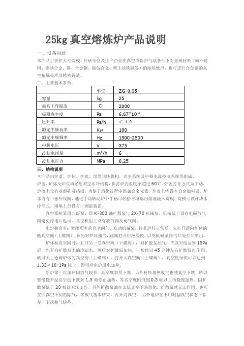
25kg真空熔炼炉产品说明一、设备用途本产品主要供大专院校、科研单位及生产企业在真空或保护气氛条件下对金属材料(如不锈钢、镍基合金、铜、合金钢、镍钴合金、稀土钕铁錋等)的熔炼处理,也可进行合金钢的真空精炼处理及精密铸造。
三、结构说明本产品由炉盖、炉体、炉底、坩埚回转机构、真空系统及中频电源控制系统等组成。
炉盖、炉体及炉底均采用双层水冷结构,保持炉壳温度不超过60℃。
炉盖打开方式为手动,炉盖上设有观察孔及挡板,为便于熔化过程中添加合金元素,炉盖上特设有合金加料器。
炉体内有一感应线圈,通过手动转动炉外手柄可轻松将坩埚内熔液浇入锭模,锭模可设计成水冷形式。
坩埚上部设有一测温装置。
真空系统采用二级泵,即K-300油扩散泵与2X-70机械泵,机械泵上设有电磁放气阀避免停电后返油。
真空机组上设有放气阀及充气阀。
电炉抽真空:紧闭所有的真空阀门,启动机械泵,待其运转正常后,先打开通向炉体的低真空阀(上蝶阀),预先对炉体抽气,此阀打开时应缓慢,以免机械泵排气口处有油喷出。
炉体抽真空同时,打开另一低真空阀(下蝶阀),对扩散泵抽气,当真空度达到15Pa 后,先开启扩散泵上的冷却水,然后对扩散泵加热,一般经过45分钟左右扩散泵起作用,就可关上通向炉体的真空阀(上蝶阀),打开大真空阀(主蝶阀),真空度很快可以达到1.33×10⁻¹Pa以上,即可对电炉通电加热。
新炉第一次加热因放气较多,真空度容易下跌,另外材料加热放气也使真空下跌,所以要慢慢升温真空度下跌到1.5帕停止加热,等真空度回升到0.5帕以上再慢慢加热。
因扩散泵低于20帕就无法工作,另外扩散泵油在太低真空下易氧化,扩散泵就无法作用。
也可在低真空下加热除气,等放气基本结束,再开高真空。
另外电炉在不用时抽真空状态下保存,下次抽气快些。
欲停止抽真空,应先关闭高真空阀(主蝶阀),然后停止加热,1个半小时后,关闭低真空阀,停止机械泵运转,只有在扩散泵完全冷却之后,才切断其冷却水供应。
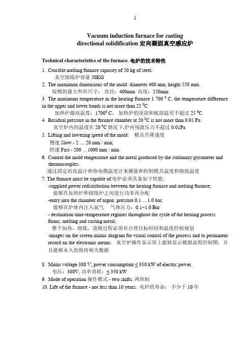
Vacuum induction furnace for castingdirectional solidification定向凝固真空感应炉Technical characteristics of the furnace. 电炉的技术特性1.Crucible melting furnace capacity of 50 kg of steel.真空熔炼炉容量 50KG2.The maximum dimensions of the mold: diameter 400 mm, height 550 mm.锭模的最大外形尺寸:直径:400mm 高度:550mm3.The maximum temperature in the heating furnace 1 700 0 C, the temperature difference in the upper and lower bands is not more than 25 0C.加热炉最高温度:17000 C,加热炉的顶部和底部温差不超过25 0C.4.Residual pressure in the furnace chamber at 20 0C is not more than 0.01 Pa.真空炉内的温度在20 0C情况下,炉内残留压力不超过0.01Pa5.Lifting and lowering speed of the mold: 模具升降速度慢速 Slow - 2 .... 20 mm / min;快速Fast - 200 ... 1000 mm / min.6.Control the mold temperature and the metal produced by the stationary pyrometer and thermocouples.通过固定的高温计和热电偶温度计来测量和控制模具温度和熔炼温度7. The furnace must be capable of电炉必须具备如下性能:-supplied power redistribution between the heating furnace and melting furnace;能够在加热炉和熔炼炉之间进行功率再分配-entry into the chamber of argon: pressure 0.1 ... 1.0 bar;能够在炉体内注入氩气气体压力:0.1~1.0 Bar- destination time-temperature regimes throughout the cycle of the heating processforms, melting and casting metal;整个加热,熔炼,浇铸过程必须有合理目标时间和温度控制规划-images on the screen mimic diagram for visual control of the process and to permanent record an the electronic means. 真空炉操作显示屏上能够显示模拟流程控制图,并且能够永久的保持相关数据8. Mains voltage 380 V, power consumption ≤ 350 kW of electric power.电压:380V, 功率消耗:≤ 350 kW9. Mode of operation 操作模式 - two shifts. 两班制10. Life of the furnace - not less than 10 years. 电炉的寿命:不少于10年Diagram and description of the furnace. 图纸和真空炉描述Fig. 1 第一张图 - Diagram of the device ; 真空炉的剖面图Fig. 2第二张图 - Side cover the heating chamber with the melter furnace - section A-A of 加热炉侧面的盖带有部熔炼炉图纸 A-A俯视图Fig. 3 第3张图- fixing unit in a mold heating furnace – view a «B» Fig. 1: Option 1;模具加热炉内固定装置的图纸Fig. 4 第4张图- Isolation valve – view a «C» in Fig. 1; 隔离阀侧视图Fig. 5 第5张图- Drive vertical rod – view a «D» in Fig. 1; 锭模垂直移动螺杆正视图Fig. 6 第6张图- The rotary drive shaft square – view a «E» in Fig.1 ;旋转导电转轴局部图Name of position: 图纸上面部件名称标注1 - The heating chamber 加热室2 - The cooling chamber冷却室3 – The camera drive rod锭模垂直移动螺杆4 – Furnace 炉子5 - Crucible (Al2O3)坩埚(三氧化二铝)6 – Inductor 感应加热器7 - Metal charge (NiCrCoMo, FeCrNiMo) 金属炉料8 - The side cover of the heating chamber 加热室的侧炉门9 - Rotation drive smelting furnace熔炼炉的旋转机构10 - A reflective screen of the side cover 安装在侧炉门反射屏11 - Vacuum valve load lock chamber gate charge 加料室内的插拔阀和真空阀12 - lock chamber gate charge 加料室13 - Immersion thermocouple (tungsten - rhenium ) 插入式的热电偶温度计(钨-铼)14 - Infrared ( optical, radiation ) 红外线温度计(光学,辐射)15 - Reflective screen gate valve 插板阀反射屏16 - Casting funnel (Al2O3) 浇铸溜槽(Al2O3)17 - The resistive heating furnace 加热炉的隔热层18 - isolator ( graphite felt , Al2O3) 绝缘隔热材料(石墨毡,Al2O3 )19 - heaters heating furnace (tungsten , graphite) 加热炉的加热器(钨,石墨)20 - reflective screen heating furnace 加热炉反射屏21 - Slotted support ( molybdenum) 加热炉带沟槽支架22 - The slots between the protrusions (齿形) 支撑座卡槽23 - The mold (Al2O3) 模具(三氧化二铝)24 - slotted disc ( molybdenum) 带槽圆盘支撑(钼)25 - The protrusions 突出物26 - Water-cooled chassis 锭模水冷底座27 - Isolation Valve 隔离阀28 - water cooling unit 水冷部位29 - Removable metal container 可拆卸金属容器30 - Reflective screen for insulating valve隔离阀反射屏31 - The water-cooled container 水冷容器32 - Lower baffle 底部挡板33 - Drive movement of the lower baffle 底部挡板的垂直移动装置34 - The top baffle 顶部挡板35 - The drive rotation of the upper baffle顶部挡板的旋转装置36 - Side door of the cooling chamber 冷却室的侧门37 - Trolley with telescopic arm and forks 模具车带有可伸缩的机械手和叉38 - rod for lifting the mold 模具提升螺杆39 - Vacuum motor 真空马达40 - Worm Gear 螺纹齿轮41 - a gear - rack gear齿轮传动机构42 - The tube with a square hole 带有一个方形洞的管道43 – Pallet 托盘44 - The cavity pallet 凹型托盘45 - Square shaft 方形传动轴46 - Vacuum motor 真空马达47 - The worm gear rotation drive shaft square 方形传动轴的旋转齿轮48 - The central square hole in the shaft for enter argon 在传动轴内的方形洞,用于注入氩气的49 - Outlet hole argon 排气口(氩气)Design 设计Furnace (Fig. 1) consists of three water-cooled vacuum chamber - a heating chamber 1, the cooling chamber 2 and the camera drive rod 3.In the upper part of the heating chamber is an induction melting furnace 4, consisting of a crucible 5 (Al2O3) and the inductor 6 - designed for melting and casting the metal charge 7.真空感应炉(参照第一张图),包含3个水冷真空室:1)加热室2)冷却室3)锭模底座和移动螺杆部位。
ZG-0.025L周期式真空感应熔炼炉技术一、设备用途ZG-0.025L周期式真空感应电炉是熔炼坩埚封闭在真空室中,利用电磁感应产生的涡流热做热源(电能转换成热能)。
在真空状态下进行高温合金的真空熔炼炼、真空浇铸浇铸,从而得到高质量材料的熔炼设备。
本套电炉用于熔炼铜合金。
主要由炉体、炉盖、合金加料、测温装置、机械搅拌装置、底吹气装置、中频电源、进电装置、倾炉浇铸装置、真空系统、中频电源、电气控制系统、设备冷却系统等构成型号:ZG-0.025L表示:25kg真空感应熔炼炉,立式结构,可控硅中频电源。
二、主要参数1、熔炼炉部分名称单位数值设备总功率千瓦(Kw) 100电源电压伏(V) 380(三相)电源频率赫(Hz) 50额定容量公斤(Kg) 25中频电源功率千瓦(Kw) 50熔化时间分钟(Min) 30-40额定电压(中频输出)伏(V) 250-375额定频率赫兹(Hz) 2500最高工作温度度(℃) 2000(石墨坩埚)工作温度度(℃) 1650极限真空度帕(Pa)≦6.67X10⁻³工作真空度帕(Pa)≦6.67X10⁻²泄漏率帕/小时(Pa/h) 4.0抽真空时间:由大气压力下至工作真空度时间≦10分钟|(热炉)测温方式钨铼热电偶测温+红外线测温坩埚材质适用石墨坩埚、氧化镁坩埚、三氧化二铝坩埚、氧化钙、金属坩埚等模具形式:钢模、石墨模具、水冷模具模具高度:600mm冷却水循环量:立方米/小时(m3/h) 12.0设备布局: 长4500mm 宽3000mm 高2500mm三. ZG-0.025L周期式真空感应熔炼炉的结构ZG-0.025L周期式真空感应熔炼炉主要由:真空熔炼炉体、感应线圈、真空系统、中频电源、电控装置、测温等辅助功能系统、水冷却系统等组成组成。
4.1 熔炼炉体:熔炼炉体由主炉盖、炉体、侧开门、炉盖升降移动机构等组成。
4.1.1炉体熔炼炉体内壁为304不锈钢,外壁及加强筋为Q235碳钢,内外炉壁之间通冷却水的双层立式水冷结构,炉体内外壁之间有加强筋,足够刚度和强度,抽负压不会变形,安全可靠。
真空控制器VACUU·SELECT 紧凑款控制器(三脚架) VACUU·SELECT 紧凑款控制器(安装) VACUU·SELECT紧凑款控制器(工作台)系统中的真空技术出版说明原版操作说明书保存以供将来使用!只能在完整、未修改状态下使用和传播本文件。
用户负责,确保本文件涉及其产品的有效性。
感谢您对我们的信任,能够购买 公司的产品。
您选择了一个现代化的、高品质的产品。
内容目录1 引言 61.1 用户提示 . . . . . . . . . . . . . . . . . . . . .61.2 操作说明书的结构 . . . . . . . . . . . . . . . . .71.3 关于本说明书 . . . . . . . . . . . . . . . . . . .81.3.1 展示协议 . . . . . . . . . . . . . . . . . . .81.3.2 符号和图标 . . . . . . . . . . . . . . . . . .91.3.3 操作指导(操作步骤) . . . . . . . . . . . . . .101.3.4 缩写 . . . . . . . . . . . . . . . . . . . . .111.3.5 术语解释 . . . . . . . . . . . . . . . . . . .122 安全提示 132.1 使用 . . . . . . . . . . . . . . . . . . . . . . .132.1.1 按规定使用 . . . . . . . . . . . . . . . . . .132.1.2 错误使用 . . . . . . . . . . . . . . . . . . .142.1.3 可预见的错误使用 . . . . . . . . . . . . . . .142.2 目标组说明 . . . . . . . . . . . . . . . . . . . .152.2.1 人员资质 . . . . . . . . . . . . . . . . . . .152.2.2 职责矩阵 . . . . . . . . . . . . . . . . . . .152.2.3 个人责任 . . . . . . . . . . . . . . . . . . .162.3 安全措施 . . . . . . . . . . . . . . . . . . . . .162.3.1 保护措施,概述 . . . . . . . . . . . . . . . .162.3.2 注意危险源 . . . . . . . . . . . . . . . . . .172.3.3 ATEX 设备类别(传感器) . . . . . . . . . . . . .182.4 废弃处理 . . . . . . . . . . . . . . . . . . . . .193 产品说明 203.1 VACUU·SELECT 紧凑款 . . . . . . . . . . . . . . . .203.2 产品视图 . . . . . . . . . . . . . . . . . . . . .223.2.1 VACUU·SELECT 紧凑款(原理结构) . . . . . . . . .223.2.2 VACUU·SELECT 传感器 . . . . . . . . . . . . .253.2.3 化学吸气管道阀 . . . . . . . . . . . . . . . .263.3 VACUU·BUS 外围设备(选项) . . . . . . . . . . . . .273.4 应用示例 . . . . . . . . . . . . . . . . . . . . .283.5 远程控制系统和接口 . . . . . . . . . . . . . . . .293.5.1 串口 RS‑232 . . . . . . . . . . . . . . . . . .293 .5 .2 Modbus TCP . . . . . . . . . . . . . . . . . .294 安放和连接 304.1 运输 . . . . . . . . . . . . . . . . . . . . . . .304.2 安放 . . . . . . . . . . . . . . . . . . . . . . .304.2.1 工作台版本 . . . . . . . . . . . . . . . . . .314.2.2 三脚架版本 . . . . . . . . . . . . . . . . . .31内容4.2.3 安装版本 . . . . . . . . . . . . . . . . . . .344.3 电气接线 . . . . . . . . . . . . . . . . . . . . .364.4 真空接口 . . . . . . . . . . . . . . . . . . . . .384.5 通风接口(选项) . . . . . . . . . . . . . . . . . .405 用户界面 415.1 接通控制器 . . . . . . . . . . . . . . . . . . . .415.1.1 触摸屏 . . . . . . . . . . . . . . . . . . . .425.1.2 操作手势 . . . . . . . . . . . . . . . . . . .425.2 调整设备 . . . . . . . . . . . . . . . . . . . . .425.2.1 关于数据保存的提示 . . . . . . . . . . . . . .425.3 屏幕方向 . . . . . . . . . . . . . . . . . . . . .435.4 指示和操作元件 . . . . . . . . . . . . . . . . . .445.4.1 过程指示器(主屏幕) . . . . . . . . . . . . . .445.4.2 指示元件 . . . . . . . . . . . . . . . . . . .455.4.3 操作元件和符号 . . . . . . . . . . . . . . . .476 操作 516.1 应用 . . . . . . . . . . . . . . . . . . . . . . .516.1.1 选择和开始应用 . . . . . . . . . . . . . . . .516.1.2 通风 . . . . . . . . . . . . . . . . . . . . .546.1.3 停止应用 . . . . . . . . . . . . . . . . . . .556.2 应用参数(参数列表) . . . . . . . . . . . . . . . .556.3 图形压力曲线 . . . . . . . . . . . . . . . . . . .576.4 主菜单 . . . . . . . . . . . . . . . . . . . . . .586.4.1 应用 . . . . . . . . . . . . . . . . . . . . .596.4.2 收藏夹 . . . . . . . . . . . . . . . . . . . .607 主菜单 617.1 扩展操作 . . . . . . . . . . . . . . . . . . . . .617.1.1 应用编辑器 . . . . . . . . . . . . . . . . . .617.1.2 菜单栏和说明 . . . . . . . . . . . . . . . . .627.1.3 过程步骤概览 . . . . . . . . . . . . . . . . .637.1.4 过程结束 . . . . . . . . . . . . . . . . . . .647.1.5 编辑应用 . . . . . . . . . . . . . . . . . . .657.1.6 删除过程步骤 . . . . . . . . . . . . . . . . .677.1.7 设置 . . . . . . . . . . . . . . . . . . . . .687.1.8 设置/管理 . . . . . . . . . . . . . . . . . .707.1.9 管理/导入 ‑ 导出 . . . . . . . . . . . . . . .727.1.10 管理/VACUU·BUS . . . . . . . . . . . . . . . .737.2 数据记录器 . . . . . . . . . . . . . . . . . . . .767.3 服务 . . . . . . . . . . . . . . . . . . . . . . .777.3.1 服务信息 . . . . . . . . . . . . . . . . . . .777.3.2 诊断数据 . . . . . . . . . . . . . . . . . . .78内容8 错误排除 798.1 故障信息 . . . . . . . . . . . . . . . . . . . . .798.1.1 故障指示器 . . . . . . . . . . . . . . . . . .798.1.2 确认故障 . . . . . . . . . . . . . . . . . . .808.2 错误 – 原因 – 排除 . . . . . . . . . . . . . . .808.2.1 弹出 . . . . . . . . . . . . . . . . . . . . .808.2.2 一般错误 . . . . . . . . . . . . . . . . . . .828.3 设备保险丝 . . . . . . . . . . . . . . . . . . . .839 附录 859.1 技术信息 . . . . . . . . . . . . . . . . . . . . .859.1.1 技术数据 . . . . . . . . . . . . . . . . . . .859.1.2 铭牌 . . . . . . . . . . . . . . . . . . . . .889.1.3 接触介质的材料 . . . . . . . . . . . . . . . .899.1.4 真空数据 . . . . . . . . . . . . . . . . . . .899.2 订货数据 . . . . . . . . . . . . . . . . . . . . .909.3 许可证信息和数据保护 . . . . . . . . . . . . . . .919.4 服务 . . . . . . . . . . . . . . . . . . . . . . .929.5 关键词目录 . . . . . . . . . . . . . . . . . . . .939.6 Declaration of Conformi ty 符合性声明 – China RoHS 294引言1 引言本操作说明书是您所购买产品的组成部分。
50 公斤真空感应熔炼炉制造过程总结一、前言在熔炼工业中,真空感应熔炼炉是一种常见的熔炼设备,它可以用于生产各种金属和合金制品。
本文将对50 公斤真空感应熔炼炉的制造过程进行总结,以期为相关领域的专业人士提供一些参考和借鉴。
二、设计与规划1. 确定炉体容量和规格根据生产需求,确定真空感应熔炼炉的容量和规格,通常根据需要熔炼的金属重量来确定炉体的大小。
2. 选材与结构设计选取高温合金材料作为炉体材料,设计结构合理的炉体形状,保证炉体的强度和稳定性。
三、零部件加工与装配1. 炉体制造首先进行高温合金材料的预处理和加工,然后根据设计图纸进行炉体的各个部件的加工和制作,最后进行炉体的装配和焊接。
2. 感应线圈制作根据设计要求,选择合适的材料和尺寸进行感应线圈的制作,保证其导电性和耐高温性能。
3. 感应电源装配选取适用的感应电源设备,进行相关电路的设计和装配,确保电源输出稳定且符合熔炼工艺要求。
四、真空系统安装调试1. 真空泵安装根据炉体设计要求,选取适用的真空泵设备,进行安装和连接。
2. 真空度调试对真空系统进行调试,确保其能够达到熔炼工艺要求的真空度。
五、炉体调试1. 感应线圈参数调试对感应线圈进行相关参数的调试,确保其能够产生符合熔炼要求的感应电磁场。
2. 温度控制系统调试对炉体的温度控制系统进行调试,确保其能够稳定控制炉体温度。
六、工艺验证和调整1. 熔炼试验进行熔炼试验,验证炉体的熔炼性能和稳定性,对炉体进行相关参数的微调和优化。
2. 工艺文件编制根据熔炼试验结果,编制相关的工艺文件,确保生产过程的可控性和稳定性。
七、总结与展望本文对50 公斤真空感应熔炼炉制造过程进行了总结,通过设计与规划、零部件加工与装配、真空系统安装调试、炉体调试、工艺验证和调整等环节,详细介绍了真空感应熔炼炉的制造过程。
希望能够为相关领域的专业人士提供一些参考,也希望在未来的研究中能够进一步完善和优化这一领域的技术和工艺,为熔炼工业的发展做出更大的贡献。
ZG-0.06L周期式真空感应熔炼精密铸造炉技术方案一、设备用途ZG-0.06L周期式真空感应熔炼铸造炉是熔炼坩埚封闭在真空室中,利用电磁感应产生的涡流热做热源(电能转换成热能)。
在真空状态下进行金属的冶炼并浇铸,从而得到高质量材料的熔炼设备。
可用于精密合金、高温合金、镍基、钴基、稀土金属、多晶硅等金属的熔炼,本套电炉用于镍基、钴基合金的真空熔炼和浇铸。
主要由炉盖、转塔、炉体、炉门、合金加料装置、测温装置、捣料装置、取样装置、中频电源、进电装置、倾炉浇铸装置、加热模壳、模壳保温箱、真空系统、PLC电气控制系统、闭式冷却设备系统等构成二、技术参数1、熔炼炉技术参数:额定容量:60kg线圈尺寸:直径330mm 高度420mm线圈材质:T2铜熔化速度:30-40分钟/炉熔炼环境:真空或惰性气体状态。
炉体直径:1300mm(以设计数据为准)炉体高度:1500mm(根据模具尺寸确定)最高温度:1750℃(与坩埚材质有关,最高可以达到2200度)熔炼工作温度:1650℃坩埚材质:刚玉坩埚极限作真空度:≤6.67X10⁻³Pa (空炉、冷态、未通水)压升率:≤4Pa/h中频电源型号:IGBT-160电源额定功率:160KW电源频率:3000Hz温度测量方式:美国雷泰MR1S型双比色红外线测温仪,温度测量范围:1000-3000℃接触式测温-钨铼热电偶测温仪,浸入钢液面温度测量范围:1000-1600℃控制系统:西门子PLC控制触摸屏显示浇注方式:液控倾翻坩埚浇铸倾斜角度:-10-100°模具材质:预热模壳。
设备布局尺寸:L:6500 mm X W:4500mm X H:3800mm2、真空系统配置:熔炼真空机组:KT-400油扩散泵1台, ZJP-600罗茨泵1台,H-150机械泵1台.真空阀门:气动真空挡板阀门、真空管道:碳钢真空管道+不锈钢波纹管真空密封:腈青橡胶真空测量计:真空压力表+复合真空计ZJ-27 电离规管ZJ-52T电阻规管充气阀:手动充气压力≤0.1MPa放气阀:电动放气阀门和手动放气阀两种3、电力要求:低压配电:3相/接地/中性电源电压:380 V AC±5%,50Hz设备总功率:220KW控制电压(内部产生):24VDC4、冷却水参数冷却设备:FB-350闭式冷却塔水质:冷却水:软水喷淋水自来水冷却水量:18m3/h (循环量)最高进水温度 15℃-35℃;出水温度 <55℃.进水压力 0.15—0.3MPa5、充气系统:气体类型:氩气、氮气气源压力:0.4-0.6MPa充入炉体内压力由操作人员进行调节控制方式::手动控制方式三、主要配置及功能:配置形式:炉盖:炉盖升降机构、炉盖手动平移、观察视窗、捣料装置、红外线测温孔。
真空感应熔炼炉技术要求1.技术要求1.1 主要技术参数 规格、尺寸、基本安装条件 立式炉体 一次出钢量 达到500Kg 额定功率 400kw 额定电压(感应端电压) 500V 最高温度 1700℃ 额定频率 700Hz ,1000Hz 。
极限真空度 6.7×10⁻²Pa 压升率 ≤1Pa/h 耗水量 40m 3/h 成套设备总重量约 40t ZL-800油增压泵功率 30kw ZJP-1200DV 罗茨泵功率 2×11Kw (真空感应熔炼炉配置两台罗茨泵) 2H-150DV 滑阀泵电机功率 2×11Kw (真空感应熔炼炉配置两台滑阀泵) 成套设备总功率 约500 Kw 电源 IGBT 双频电源1.2设备关键部件规格要求序号 名称 型号、材质要求 制造厂要求 1 炉体内壁304不锈钢,外壁碳钢 2 滑阀泵 型号2H-150DV 三门拓展真空设备有限公司生产或同级别产品3罗茨泵 型号Z J P-1200DV 三门拓展真空设备有限公司或同级别产品 4油增压喷射泵 型号Z-800 甘肃腾飞有限公司或同级别产品 5旋片泵 型号2X-70、2X-8 三门拓展真空设备有限公司或同级别产品 6真空气动蝶阀 型号GIQ-80 上海阀门二厂或 宁波仪表阀门厂 7隔膜阀 型号GM-10F 、GM-40F 上海阀门二厂或 宁波仪表阀门厂 8真空计 型号ZDF-Ⅲ复合真空计 成都睿宝或成都成华 9300气动插板阀 不锈钢产品 上海阀门二厂或同级别产品 10 电源400KW,IGBT 电源, 双频电源,700Hz 和1000Hz 。
配有漏钢自动保护和自动报警功能 张家港四通或同级别产品 11各电机 节能电机,达到标准IE2以上 12 钢锭摆放量最多可摆放6个钢锭模,步进式,浇注高度1.25米,浇注平台宽度1.5米 13密封胶圈 密封胶圈的设计要避免高温高辐射,接触高温高辐射部分健全要求使用硅橡胶或其它耐高温橡胶 14红外测温 700℃-1800℃,MR 系列 美国雷泰或同级别产品 15PLC 德国西门子或同级别产品1.3、设备结构说明成套设备由真空熔炼室(包括炉体、炉盖)、真空系统、液压系统、水冷系统、气动系统、主加料装置、合金加料箱及料斗翻转机构、观察窗、进电装置、测温装置、捣料装置、工作台、锭模车、IGBT中频电源柜及电气控制系统等部分组成,实现在真空状态下作业的工艺要求。
工艺技术方案英文Technological Solution for Manufacturing ProcessIntroduction:I. Automation and Robotics Integration:One of the key elements of this technological solution is the integration of automation and robotics in the manufacturing process. Automation can streamline repetitive tasks, improve efficiency, and reduce the risk of human error. By incorporating robots into the production line, manufacturers can achieve higher precision and accuracy, leading to better quality products.II. Internet of Things (IoT) Implementation:III. Additive Manufacturing (3D Printing):IV. Advanced Material Selection:To enhance the quality and performance of the final product, manufacturers should explore the use of advanced materials. These materials can offer improved strength, durability, and resistance to various environmental conditions. Additionally, materials with specific properties, such as lightweight and high heat resistance, can be selected to meet the requirements of specific applications.V. Energy Efficiency Measures:Manufacturers should also focus on implementing energy-efficient measures to reduce their environmental impact while optimizing operational costs. This can be achieved by using energy-efficient equipment, such as high-efficiency motors and LED lighting, implementing energy management systems, and utilizing renewable energy sources.VI. Continuous Improvement through Lean Manufacturing:VII. Quality Control and Assurance:To ensure the quality of the final products, manufacturers should implement robust quality control and assurance measures. This can include the use of statistical process control techniques, inspection and testing protocols, and a strong focus on traceability. Additionally, advanced quality management systems can be employed to monitor process deviations andtrigger corrective actions.Conclusion:。
编制依据:《钛镍加工材项目初步设计》GB/T2524-2010《海绵钛》设备合同1.主要设备性能1.1 真空自耗电弧炉技术性能。
2.原料原料来自315T制样用自耗电极成形液压机压制的¢30X390的电极3.钛及钛合金熔炼3.1 钛及其合金的熔炼工艺流程水、电、气输送正常—开机—装炉—抽真空—熔炼—坩埚冷却—破真空—取出铜坩锅倒出钛锭—停止工作—关水、关电、关气。
3.2 熔炼工艺参数3.2.2 熔铸前检查系统并进行预抽空,炉内预真空度不得低于0.133Pa,泄漏率不得大于0.667Pa/min。
3.2.3 在熔炼过程中,熔炼电流需逐渐增加。
3.2.4 在结晶器周围设有稳弧线圈,以保证熔炼电弧的稳定。
通过“稳弧调节”电位器调节其电流,最大电流为5A。
3.2.5 电弧电压的大小代表电弧的长短,熔炼过程中保证弧压的稳定非常重要。
熔炼过程中弧压的大小为 0-40V。
3.2.6补缩工艺参数实际生产中生产。
3.3 引弧料同批号的钛料、铺满坩埚底为益。
3.4 注意事项3.4.1 压制完的电极在熔炼前必须放入干燥箱内干燥20~40min,干燥温度在90~105℃之间。
3.4.2 在熔炼开炉前,必须对真空自耗电弧炉的传动系统、冷却系统、电控系统、真空系统及炉体进行检查,检查无误,方可开炉熔炼。
3.4.3 抽空真空泵使用必须遵照使用说明书的要求,进行启动、停泵、维护。
3.4.4每炉熔炼工作完成后,必须清洗结晶器。
防止熔炼时电极与结晶器侧壁放电。
3.4.5熔炼期间冷却水不能间断。
3.4.6 熔炼进行时,现场要有操作控制人员,观察炉内熔炼情况和监视冷却水水温水压等。
3.4.7 在熔炼完的铸锭或扒完皮的铸锭上,必须有明显的标记。
3.4.8 试锭和试样的制备严格按GB/T2524-2010进行。
4.主要工模具4.1 熔炼坩埚坩埚的主要结构材质为铜。
必须保证坩埚的清洁、干燥及完整性。
4.2引弧料同批号的钛料4.3熔炼用主要工具规格及材质坩埚内径尺寸(mm)Ф50X125 材质铜5.执行标准熔炼出的钛及钛合金铸锭化学成份按照国家标准GB/T3620.1-2007。