三层交换机组播配置实例
- 格式:doc
- 大小:40.50 KB
- 文档页数:3
华为三层交换机配置案例华为三层交换机配置案例下面以华三通信H3C S3600-28P-SI为例,给大家带来华为三层交换机配置案例,希望对你有帮助!配置命令system-view //进入系统视图[H3C]display current-configuration //显示当前配置//以下开始配置第一步:划分VLAN,并描述vlan 1description local-S3600vlan 2description link-to-wenquanvlan 3description link-to-ruzhouvlan 4description link-to-xiaotunvlan 5description link-to-baofengvlan 6description link-to-pingxivlan 7description link-to-pingnanvlan 8description Uplink-to-Putianvlan 9description link-to-pingxicentre第二步:给VLAN 划网关interface Vlan-interface2description link to wenquanip address 10.41.77.41 255.255.255.192 interface Vlan-interface3description link to ruzhouip address 10.41.77.105 255.255.255.192 interface Vlan-interface4description link to xiaotunip address 10.41.77.169 255.255.255.192 interface Vlan-interface5description link to baofengip address 10.41.77.233 255.255.255.192 interface Vlan-interface6description link to pingxiip address 10.41.78.41 255.255.255.192 interface Vlan-interface7description link to pingnanip address 10.41.78.105 255.255.255.192 interface Vlan-interface8description uplink to putianip address 10.41.244.102 255.255.255.252 interface Vlan-interface9description link to pingxicentreip address 10.41.80.233 255.255.255.192 第三步:给VLAN 指定端口interface Ethernet1/0/2description link to wenquanport access vlan 2interface Ethernet1/0/3description link to ruzhouport access vlan 3interface Ethernet1/0/4description link to xiaotunport access vlan 4interface Ethernet1/0/5description link to baofengport access vlan 5interface Ethernet1/0/6description link to pingxiport access vlan 6interface Ethernet1/0/7description link to pingnanport access vlan 7interface Ethernet1/0/8description uplink to putianport access vlan 8interface Ethernet1/0/9 to Ethernet1/0/24description link to pingxicentreport access vlan 9第四步:配置路由协议//(1)用RIP配动态路由ripnetwork 10.41.77.41network 10.41.77.105network 10.41.77.169network 10.41.77.233network 10.41.78.41network 10.41.78.105network 10.41.80.233network 10.41.244.102//(2)配静态路由(只用对远端设备配一条路由即可,本地自通)---推荐用此协议ip route 0.0.0.0 0.0.0.0 10.41.244.101案例:华为S3600三层交换机配置方法sys[Quidway]vlan 2[Quidway-vlan2]port e1/0/2[Quidway-vlan2]int vlan 2[Quidway-Vlan-interface2]ip add 10.41.77.41 255.255.255.192 //温泉网关[Quidway-Vlan-interface2]vlan 3[Quidway-vlan3]port e1/0/3[Quidway-vlan3]int vlan 3[Quidway-Vlan-interface3]ip add 10.41.77.105 255.255.255.192 //汝州网关[Quidway-Vlan-interface3]vlan 4[Quidway-vlan4]port e1/0/4[Quidway-vlan4]int vlan 4[Quidway-Vlan-interface4]ip add 10.41.77.169 255.255.255.192 //小屯网关[Quidway-Vlan-interface4]vlan 5[Quidway-vlan5]port e1/0/5[Quidway-vlan5]int vlan 5[Quidway-Vlan-interface5]ip add 10.41.77.233 255.255.255.192 //宝丰网关[Quidway-Vlan-interface5]vlan 6[Quidway-vlan6]port e1/0/6[Quidway-vlan6]int vlan 6[Quidway-Vlan-interface6]ip add 10.41.78.41 255.255.255.192 //平西网关[Quidway-Vlan-interface6]vlan 7[Quidway-vlan7]port e1/0/7[Quidway-vlan7]int vlan 7[Quidway-Vlan-interface7]ip add 10.41.78.105 255.255.255.192 //平南网关[Quidway-Vlan-interface7]vlan 8[Quidway-vlan8]port e1/0/8[Quidway-vlan8]int vlan 8[Quidway-Vlan-interface8]ip add 10.41.244.102 255.255.255.252 //省中心网关[Quidway-Vlan-interface8]vlan 9[Quidway-vlan9]port e1/0/9 to e1/0/24[Quidway-vlan9]int vlan 9[Quidway-Vlan-interface9]ip add 10.41.80.233 255.255.255.192 //分中心网关//配置路由ip route 0.0.0.0 0.0.0.0 10.41.244.101华为三层交换机上如何实现不同vlan间的通信命令如下:一、组网需求:交换机配置了4个VLAN,分别为VLAN1,VLAN2,VLAN3,VLAN4,要求VLAN1可以与VLAN2,3,4互访,但是VLAN2,3,4之间不能互访,用Hybrid端口属性实现此功能。
Dell三层交换机配置实例在这个文档中,我们将提供一些关于Dell三层交换机配置的实例。
这将帮助您了解如何正确配置和管理这些交换机,使其能够满足您的网络需求。
1. 配置VLAN要配置VLAN,请按照以下步骤操作:1. 使用管理员账户登录到Dell三层交换机的管理界面。
2. 打开命令行界面,并输入以下命令以进入全局配置模式:configure3. 创建一个新的VLAN,输入以下命令并替换`vlan_id`和`vlan_name`为您想要的VLAN的ID和名称:vlan databasevlan vlan_id name vlan_name4. 将一个或多个端口分配给VLAN,输入以下命令并替换`interface_range`和`vlan_id`为您要配置的界面范围和VLAN的ID:interface range interface_rangeswitchport access vlan vlan_id5. 保存配置并退出全局配置模式,输入以下命令:wrexit2. 配置静态路由要配置静态路由,请按照以下步骤操作:1. 使用管理员账户登录到Dell三层交换机的管理界面。
2. 打开命令行界面,并输入以下命令以进入全局配置模式:configure3. 添加静态路由,输入以下命令并替换`destination_network`,`next_hop_ip`和`interface`为您要配置的目标网络、下一跳IP和接口:ip route destination_network next_hop_ip interface4. 保存配置并退出全局配置模式,输入以下命令:wrexit3. 配置端口聚合要配置端口聚合,请按照以下步骤操作:1. 使用管理员账户登录到Dell三层交换机的管理界面。
2. 打开命令行界面,并输入以下命令以进入全局配置模式:configure3. 创建一个聚合组,输入以下命令并替换`group_number`为您想要创建的聚合组的编号:interface port-channel group_number4. 将端口添加到聚合组,输入以下命令并替换`interface_range`为要添加的端口范围:interface range interface_rangechannel-group group_number mode on5. 配置聚合组的参数,例如速度和模式,输入以下命令并替换`group_number`、`speed`和`mode`为您想要配置的聚合组的编号、速度和模式:interface port-channel group_numberspeed speedmode mode6. 保存配置并退出全局配置模式,输入以下命令:wrexit希望这些配置实例可以帮助您正确地配置Dell三层交换机。
三层交换机的配置实例三层交换机的配置实例1、交换机配置模版(以迈普4152E 交换机为例)hostname HEBSJZZXCG5_WN_AS02service password-encryptno service new-encryptservice login-secureenable password maipuuser admin password 0 adminip access-list standard 110 permit 10.59.16.0 0.0.0.25520 permit 10.59.18.0 0.0.0.255exitip access-list standard telnet_acl10 permit 10.59.16.0 0.0.0.25520 permit 100.255.1.0 0.0.0.25530 permit 100.255.0.0 0.0.0.255exitaaa new-modelaaa authentication login default tacacs localaaa authentication enable default tacacs enableaaa authorization exec default tacacs localaaa authorization commands 1 default tacacs local aaa authorization commands 15 default tacacs local aaa accounting exec default start-stop tacacsaaa accounting commands 1 default start-stop tacacs aaa accounting commands 15 default start-stop tacacs ip ctrl-protocol unicastip ctrl-protocol multicastip load-sharing per-destinationvlan 1exitvlan 2021description TO-HEBSJZZX3_WN_AS01 exit vlan 2051description TO-2600C-ABISexitvlan 2052description TO-2600C-OAexitvlan 2053description TO-2600C-TESTexit!slot_0_S4152E!slot 0/0port 0/0/0port-type nniport access vlan 2021exitport 0/0/1port-type nniport access vlan 2021exitport 0/0/2port-type nniport access vlan 2021exitport 0/0/3port-type nniport access vlan 2021 exitport 0/0/4port-type nniport access vlan 2021 exitport 0/0/5port-type nniexitport 0/0/6port-type nniport access vlan 2021 exit port 0/0/7port-type nniport access vlan 2021 exit port 0/0/8port-type nniport access vlan 2021 exit port 0/0/9port-type nniport access vlan 2021 exit port 0/0/10port-type nniport access vlan 2021 exit port 0/0/11port-type nniport access vlan 2021 exit port 0/0/12port-type nniport access vlan 2021 exitport-type nniport access vlan 2021 exit port 0/0/14port-type nniport access vlan 2021 exit port 0/0/15port-type nniport access vlan 2021 exit port 0/0/16port-type nniexitport 0/0/17port-type nniport access vlan 2021 exit port 0/0/18port-type nniport access vlan 2021 exit port 0/0/19port-type nniport access vlan 2021 exit port 0/0/20port-type nniport access vlan 2021 exit port 0/0/21port-type nniport access vlan 2021 exit port 0/0/22port-type nniport access vlan 2021 exitport-type nniport access vlan 2021 exit port 0/0/24port-type nniport access vlan 2021 exit port 0/0/25port-type nniport access vlan 2021 exit port 0/0/26port-type nniport access vlan 2021 exit port 0/0/27port-type nniexitport 0/0/28port-type nniport access vlan 2021 exit port 0/0/29port-type nniport access vlan 2021 exit port 0/0/30port-type nniport access vlan 2021 exit port 0/0/31port-type nniport access vlan 2021 exit port 0/0/32port-type nniport access vlan 2051 exitport-type nniport access vlan 2051 exit port 0/0/34port-type nniport access vlan 2051 exit port 0/0/35port-type nniport access vlan 2051 exit port 0/0/36port-type nniport access vlan 2051 exit port 0/0/37port-type nniport access vlan 2051 exit port 0/0/38port-type nniexitport 0/0/39port-type nniport access vlan 2051 exitport 0/0/40port-type nniport access vlan 2051 exitport 0/0/41port-type nniport access vlan 2051 exitport-type nniport access vlan 2052exitport 0/0/43port-type nniport access vlan 2052exitport 0/0/44port-type nniport access vlan 2052exitport 0/0/45port-type nniport access vlan 2052exitport 0/0/46description TO-HEBSJZZX2_WN_AS03 port-type nni port mode trunkport trunk allowed vlan allport trunk pvid vlan 1traffic-shape 10240 12288exitport 0/0/47description TO-2600Cport-type nniport mode trunkport trunk allowed vlan allport trunk pvid vlan 1!end!slot_1_SM41-4GE!slot 0/1port 0/1/0port-type nniport access vlan 2053exitport 0/1/1port-type nniport access vlan 2053exitport 0/1/2port-type nniexitport 0/1/3port-type nniexitinterface vlan 1description TO-9512E-GUANLIip address 100.255.1.131 255.255.255.0exitip route 0.0.0.0 0.0.0.0 100.255.1.254logging 10.59.18.1 0 6line vty 0 15exec-timeout 0 300login localexitsnmp-server startsnmp-server view default 1.3.6.1 includesnmp-server community public view default ro 1snmp-server host 130.25.2.103 traps community publicversion 2 snmp-server trap-source 10.6.24.222 snmp-server enable traps snmp authentication snmp-server enable traps snmp linkdownsnmp-server enable traps snmp linkup2、配置操作3、网点迈普4152E交换机配置模版enaconf tvlan 2051description ABISexitvlan 2052description OAexitvlan 2053description TESTexitvlan 2054description waiwangexitport 0/0/0-0/0/47port-type nniport 0/0/0-0/0/29port access vlan 2051exitport 0/0/30-0/0/39port access vlan 2052exitport 0/0/40-0/0/44port access vlan 2054exitport 0/0/45-0/0/47port access vlan 2053 exit exitwr。
三层交换机14-IPv6组播VLAN典型配置举例H3C S5130-EI IPv6 组播VLAN 典型配置举例目录1 简介 (1)2 配置前提 (1)3 基于子VLAN的IPv6 组播VLAN (1)3.1 组网需求 (1)3.1.1 现网描述 (1)3.2 配置思路 (3)3.3 使用版本 (3)3.4 配置注意事项 (3)3.5 配置步骤 (4)3.6 验证配置 (5)3.7 配置文件 (5)4 基于端口的IPv6 组播VLAN (7)4.1 组网需求 (7)4.1.1 现网描述 (7)4.1.2 需求描述 (8)4.2 配置思路 (9)4.3 使用版本 (9)4.4 配置注意事项 (9)4.5 配置步骤 (10)4.6 验证配置 (12)4.7 配置文件 (12)5 相关资料 (14)1 简介本文档介绍了基于子VLAN 的IPv6 组播VLAN 和基于端口的IPv6 组播VLAN 的配置举例。
2 配置前提本文档中的配置均是在实验室环境下进行的配置和验证,配置前设备的所有参数均采用出厂时的缺省配置。
如果您已经对设备进行了配置,为了保证配置效果,请确认现有配置和以下举例中的配置不冲突。
本文假设您已了解IPv6 组播VLAN 特性。
3 基于子VLAN的IPv6 组播VLAN3.1 组网需求3.1.1 现网描述如图1 所示,某楼层分布了两个不同的部门,通过在Switch B上配置不同的VLAN来区分这两个部门,其中用户VLAN 10、VLAN 20 分别标识了部门1、部门2。
交换机Switch A上配置了VLAN 10、VLAN 20 对应的VLAN虚接口,分别作为用户VLAN的网关。
由于业务需要,部门1 中有多台主机需要同时接收网络中某一发送源发送的数据。
该企业采用了IPv6 组播的传输方式:在Switch A 的Vlan-interface10 上运行MLDv1。
同时为避免组播数据在数据链路层的广播问题,该企业在交换机Switch B 的VLAN 10 内开启了版本 1 的MLD Snooping功能。
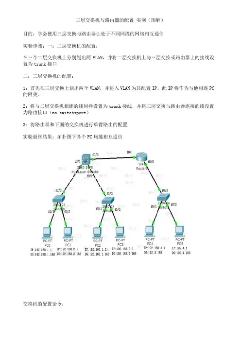
三层交换机与路由器的配置实例(图解)目的:学会使用三层交换与路由器让处于不同网段的网络相互通信实验步骤:一:二层交换机的配置:在三个二层交换机上分别划出两VLAN,并将二层交换机上与三层交换或路由器上的接线设置为trunk接口二:三层交换机的配置:1:首先在三层交换上划出两个VLAN,并进入VLAN为其配置IP,此IP将作为与他相连PC 的网关。
2:将与二层交换机相连的线同样设置为trunk接线,并将三层交换与路由器连接的线设置为路由接口(no switchsport)3:将路由器和下面的交换机进行单臂路由的配置实验最终结果:拓扑图下各个PC均能相互通信交换机的配置命令:SW 0:Switch>Switch>enSwitch#confConfiguring from terminal, memory, or network [terminal]?Enter configuration commands, one per line. End with CNTL/Z.Switch(config)#vlan 2Switch(config-vlan)#exitSwitch(config)#int f0/2Switch(config-if)#switchport access vlan 2Switch(config-if)#no shutSwitch(config-if)#int f0/3Switch(config-if)#switchport mode trunk%LINEPROTO-5-UPDOWN: Line protocol on Interface FastEthernet0/3, changed state to down%LINEPROTO-5-UPDOWN: Line protocol on Interface FastEthernet0/3, changed state to upSwitch(config-if)#exitSwitch(config)#SW 1:Switch>enSwitch#confConfiguring from terminal, memory, or network [terminal]?Enter configuration commands, one per line. End with CNTL/Z.Switch(config)#int f0/2Switch(config-if)#switchport access vlan 2% Access VLAN does not exist. Creating vlan 2Switch(config-if)#no shutSwitch(config-if)#exitSwitch(config)#int f0/3Switch(config-if)#switchport mode trunk%LINEPROTO-5-UPDOWN: Line protocol on Interface FastEthernet0/3, changed state to down%LINEPROTO-5-UPDOWN: Line protocol on Interface FastEthernet0/3, changed state to upSwitch(config-if)#SW 2:Switch>enSwitch#confConfiguring from terminal, memory, or network [terminal]?Enter configuration commands, one per line. End with CNTL/Z.Switch(config)#int f0/2Switch(config-if)#switchport access vlan 2% Access VLAN does not exist. Creating vlan 2Switch(config-if)#exitSwitch(config)#int f0/3Switch(config-if)#switchport mode trunkSwitch(config-if)#三层交换的配置命令:Switch>enSwitch#confConfiguring from terminal, memory, or network [terminal]?Enter configuration commands, one per line. End with CNTL/Z.Switch(config)#int f0/1Switch(config-if)#switchport mode trunk%LINEPROTO-5-UPDOWN: Line protocol on Interface FastEthernet0/2, changed state to downSwitch(config-if)#exitSwitch(config)#int f0/2Switch(config-if)#switchport mode trunkSwitch(config-if)#exitSwitch(config)#vlan 2Switch(config-vlan)#exitSwitch(config)#int vlan 1Switch(config-if)#no shut%LINK-5-CHANGED: Interface Vlan1, changed state to up%LINEPROTO-5-UPDOWN: Line protocol on Interface Vlan1, changed state to up Switch(config-if)#ip address 192.168.1.168 255.255.255.0Switch(config-if)#exitSwitch(config)#int vlan 2%LINK-5-CHANGED: Interface Vlan2, changed state to up%LINEPROTO-5-UPDOWN: Line protocol on Interface Vlan2, changed state to upSwitch(config-if)#ip addSwitch(config-if)#ip address 192.168.2.168 255.255.255.0Switch(config-if)#%LINK-5-CHANGED: Interface FastEthernet0/3, changed state to up%LINEPROTO-5-UPDOWN: Line protocol on Interface FastEthernet0/3, changed state to upSwitch(config-if)#exitSwitch(config)#int f0/3Switch(config-if)#no switchport%LINEPROTO-5-UPDOWN: Line protocol on Interface FastEthernet0/3, changed state to down%LINEPROTO-5-UPDOWN: Line protocol on Interface FastEthernet0/3, changed state to upSwitch(config-if)#Switch(config-if)#ip address 192.168.10.1 255.255.255.0Switch(config-if)#no shutSwitch(config-if)#exitSwitch(config)#ip routingSwitch(config-if)#exitSwitch(config)#ip route 0.0.0.0 0.0.0.0 192.168.10.2Switch(config)#路由器的配置:Router>enRouter#confConfiguring from terminal, memory, or network [terminal]?Enter configuration commands, one per line. End with CNTL/Z.Router(config)#int f0/0Router(config-if)#no shut%LINK-5-CHANGED: Interface FastEthernet0/0, changed state to upRouter(config-if)#exitRouter(config)#int f0/1Router(config-if)#no shut%LINK-5-CHANGED: Interface FastEthernet0/1, changed state to up%LINEPROTO-5-UPDOWN: Line protocol on Interface FastEthernet0/1, changed state to upRouter(config-if)#exitRouter(config)#int f0/0Router(config-if)#no shutRouter(config-if)#exitRouter(config)#int f0/0.1Router(config-subif)#encapsulation dot1Q 1Router(config-subif)#ip address 192.168.3.168 255.255.255.0Router(config-subif)#exitRouter(config)#int f0/0.2Router(config-subif)#encapsulation dot1Q 2Router(config-subif)#ip addRouter(config-subif)#ip address 192.168.4.168 255.255.255.0Router(config-subif)#exitRouter(config)#ip route 0.0.0.0 0.0.0.0 192.168.10.1Router(config)#exit%SYS-5-CONFIG_I: Configured from console by consoleRouter#confConfiguring from terminal, memory, or network [terminal]?Enter configuration commands, one per line. End with CNTL/Z.Router(config)#int f0/1Router(config-if)#ip addRouter(config-if)#ip address 192.168.10.2 255.255.255.0 Router(config-if)#。

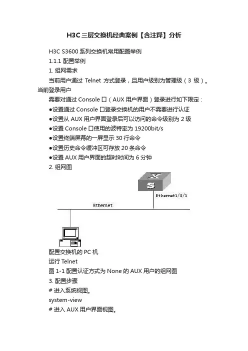
H3C三层交换机经典案例【含注释】分析H3C S3600系列交换机常用配置举例1.1.1 配置举例1. 组网需求当前用户通过Telnet方式登录,且用户级别为管理级(3级)。
当前登录用户需要对通过Console口(AUX用户界面)登录进行如下限定:●设置通过Console口登录交换机的用户不需要进行认证●设置从AUX用户界面登录后可以访问的命令级别为2级●设置Console口使用的波特率为19200bit/s●设置终端屏幕的一屏显示30行命令●设置历史命令缓冲区可存放20条命令●设置AUX用户界面的超时时间为6分钟2. 组网图配置交换机的PC机运行Telnet图1-1配置认证方式为None的AUX用户的组网图3. 配置步骤# 进入系统视图。
system-view# 进入AUX用户界面视图。
[H3C] user-interface aux 0# 设置通过Console口登录交换机的用户不需要进行认证。
[H3C-ui-aux0] authentication-mode none# 设置从AUX用户界面登录后可以访问的命令级别为2级。
[H3C-ui-aux0] user privilege level 2# 设置Console口使用的波特率为19200bit/s。
[H3C-ui-aux0] speed 19200# 设置终端屏幕的一屏显示30行命令。
[H3C-ui-aux0] screen-length 30# 设置历史命令缓冲区可存放20条命令。
[H3C-ui-aux0] history-command max-size 20# 设置AUX用户界面的超时时间为6分钟。
[H3C-ui-aux0] idle-timeout 61.1.2 配置举例1. 组网需求当前用户通过Telnet方式登录,且用户级别为管理级(3级)。
当前登录用户需要对通过Console口(AUX用户界面)登录进行如下限定:●设置通过Console口登录交换机的用户进行Password认证●设置用户的认证口令为明文方式,口令为123456●设置从AUX用户界面登录后可以访问的命令级别为2级●设置Console口使用的波特率为19200bit/s●设置终端屏幕的一屏显示30行命令●设置历史命令缓冲区可存放20条命令●设置AUX用户界面的超时时间为6分钟2. 组网图配置交换机的PC机运行Telnet图1-2配置认证方式为Password的AUX用户的组网图3. 配置步骤# 进入系统视图。

三层交换机配置实例三层交换综合实验一般来讲,设计方案中主要包括以下内容:◆∙∙∙∙∙ 用户需求◆∙∙∙∙∙ 需求分析◆∙∙∙∙∙ 使用什么技术来实现用户需求◆∙∙∙∙∙ 设计原则◆∙∙∙∙∙ 拓扑图◆∙∙∙∙∙ 设备清单一、模拟设计方案【用户需求】1.应用背景描述某公司新建办公大楼,布线工程已经与大楼内装修同步完成。
现公司需要建设大楼内部的办公网络系统。
大楼的设备间位于大楼一层,可用于放置核心交换机、路由器、服务器、网管工作站、电话交换机等设备。
在每层办公楼中有楼层配线间,用来放置接入层交换机与配线架。
目前公司工程部25人、销售部25人、发展部25人、人事部10人、财务部加经理共15人。
2.用户需求为公司提供办公自动化、计算机管理、资源共享及信息交流等全方位的服务,目前的信息点数大约100个,今后有扩充到200个的可能。
公司的很多业务依托于网络,要求网络的性能满足高效的办公要求。
同时对网络的可靠性要求也很高,要求在办公时间内,网络不能宕掉。
因此,在网络设计过程中,要充分考虑到网络设备的可靠性。
同时,无论是网络设备还是网络线路,都应该考虑冗余备份。
不能因为单点故障,而导致整个网络的瘫痪,影响公司业务的正常进行。
公司需要通过专线连接外部网络。
【需求分析】为了实现网络的高速、高性能、高可靠性还有冗余备份功能,主要用于双核心拓扑结构的网络中。
本实验采用双核心拓扑结构,将三层交换技术和VTP、STP、EthernetChannel综合运用。
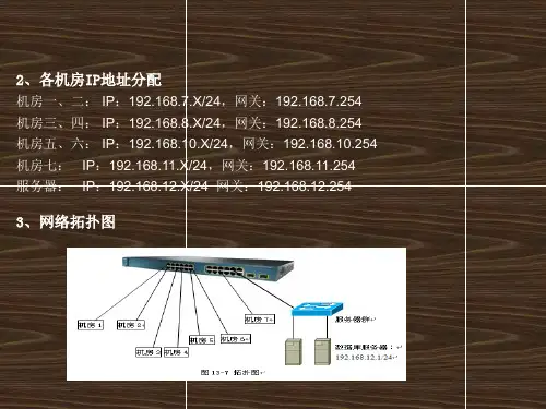
【设计方案】1、在交换机上配置VLAN,控制广播流量2、配置2台三层交换机之间的EthernetChannel,实现三层交换机之间的高速互通3、配置VTP,实现单一平台管理VLAN,同时启用修剪,减少中继端口上不必要的广播信息量4、配置STP,实现冗余备份、负载分担、避免环路5、在三层交换机上配置VLAN间路由,实现不同VLAN之间互通6、通过路由连入外网,可以通过静态路由或RIP路由协议【网络拓扑】根据用户对可靠性的要求,我们将网络设计为双核心结构,为了保证高性能,采用双核心进行负载分担。
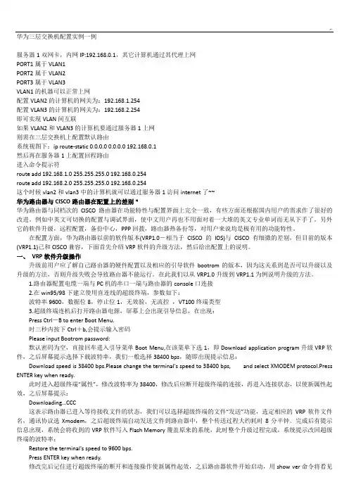
华为三层交换机配置实例一例服务器1双网卡,内网IP:192.168.0.1,其它计算机通过其代理上网PORT1属于VLAN1PORT2属于VLAN2PORT3属于VLAN3VLAN1的机器可以正常上网配置VLAN2的计算机的网关为:192.168.1.254配置VLAN3的计算机的网关为:192.168.2.254即可实现VLAN间互联如果VLAN2和VLAN3的计算机要通过服务器1上网则需在三层交换机上配置默认路由系统视图下:ip route-static 0.0.0.0 0.0.0.0 192.168.0.1然后再在服务器1上配置回程路由进入命令提示符route add 192.168.1.0 255.255.255.0 192.168.0.254route add 192.168.2.0 255.255.255.0 192.168.0.254这个时候vlan2和vlan3中的计算机就可以通过服务器1访问internet了~~华为路由器与CISCO路由器在配置上的差别"华为路由器与同档次的CISCO路由器在功能特性与配置界面上完全一致,有些方面还根据国内用户的需求作了很好的改进。
例如中英文可切换的配置与调试界面,使中文用户再也不用面对着一大堆的英文专业单词而无从下手了。
另外它的软件升级,远程配置,备份中心,PPP回拨,路由器热备份等,对用户来说均是极有用的功能特性。
在配置方面,华为路由器以前的软件版本(VRP1.0-相当于CISCO的IOS)与CISCO有细微的差别,但目前的版本(VRP1.1)已和CISCO兼容,下面首先介绍VRP软件的升级方法,然后给出配置上的说明。
一、VRP软件升级操作升级前用户应了解自己路由器的硬件配置以及相应的引导软件bootrom的版本,因为这关系到是否可以升级以及升级的方法,否则升级失败会导致路由器不能运行。
在此我们以从VRP1.0升级到VRP1.1为例说明升级的方法。
H3C三层交换机配置实例H3C三层交换机配置实例1 网络拓扑图 (1)2 配置要求 (1)3划分VLAN并描述 (2)进入系统视图 (2)创建VLAN并描述 (2)4 给VLAN设置网关 (3)VLAN1的IP地址设置 (3)VLAN100的网关设置 (3)VLAN101的网关设置 (3)VLAN102的网关设置 (3)VLAN103的网关设置 (4)5 给VLAN指定端口,设置端口类型 (4) VLAN100指定端口 (4)VLAN102指定端口 (4)VLAN1/101/103指定端口 (5)6 配置路由协议 (6)默认路由 (6)配置流分类 (6)定义行为 (6)应用QOS策略 (6)接口配置QOS策略 (7)1 网络拓扑图图1-1 网络拓扑图2 配置要求用户1网络:/24 至出口1网络:/24用户2网络:/24 至出口2网络:/24实现功能:用户1通过互联网出口1,用户2通过互联网出口2。
3划分VLAN并描述进入系统视图system-view //进入系统视图图3-1 系统视图创建VLAN并描述[H3C]vlan 1 //本交换机使用[H3C-vlan1]description Manager //描述为“Manager”[H3C-vlan1]quit[H3C]vlan 100 //划分vlan100[H3C-vlan100]description VLAN 100 //描述为“VLAN100”[H3C-vlan100]quit[H3C]vlan 101 //划分vlan101[H3C-vlan101]description VLAN 101 //描述为“VLAN 101”[H3C-vlan101]quit[H3C]vlan 102 //划分vlan102[H3C-vlan102]description VLAN 102 //描述为“VLAN 102”[H3C-vlan102]quit[H3C]vlan 103 //划分vlan103[H3C-vlan103]description VLAN 103 //描述为“VLAN 103”[H3C-vlan103]quit[H3C]图3-2 划分VLAN及描述4 给VLAN设置网关VLAN1的IP地址设置把VLAN1的IP地址设置为,子网掩码为,用于本地使用。
[配置实例]三层交换机组播配置实例「配置环境参数」 1. 组播服务器地址为192.168.0.10/24,⽹关为192.168.0.1/24 2. 三层交换机SwitchA通过上⾏⼝G1/1连接组播服务器,交换机连接组播服务器接⼝interface vlan 100,地址为192.168.0.1.3. vlan10和vlan20下挂两个⼆层交换机SwitchB和SwitchC,地址为10.10.10.1/24和10.10.20.1/24. 「组⽹需求」 1:在SwitchA、SwitchB和SwitchC上运⾏组播协议,要求L3上配置为IP PIM-SM模式 2:数据配置步骤「PIM-SM数据流程」 PIM-SM(Protocol Independent Multicast,Sparse Mode)即与协议⽆关的组播稀疏模式,属于稀疏模式的组播路由协议。
PIM-SM主要⽤于组成员分布相对分散、范围较⼴、⼤规模的⽹络。
与密集模式的扩散?剪枝不同,PIM-SM协议假定所有的主机都不需要接收组播数据包,只有主机明确指定需要时,PIM-SM路由器才向它转发组播数据包。
PIM-SM协议中,通过设置汇聚点RP(Rendezvous Point)和⾃举路由器BSR(Bootstrap Router),向所有PIM-SM路由器通告组播信息,并利⽤路由器的加⼊/剪枝信息,建⽴起基于RP的共享树RPT(RP-rooted shared tree)。
从⽽减少了数据报⽂和控制报⽂占⽤的⽹络带宽,降低路由器的处理开销。
组播数据沿着共享树流到该组播组成员所在的⽹段,当数据流量达到⼀定程度,组播数据流可以切换到基于源的最短路径树SPT,以减少⽹络延迟。
PIM-SM不依赖于特定的单播路由协议,⽽是使⽤现存的单播路由表进⾏RPF检查。
运⾏PIM-SM协议,需要配置候选RP和BSR,BSR负责收集候选RP发来的信息,并把它们⼴播出去。
全面的三层交换机配置实例(带命令解释)三层交换机比较全面的三层交换机配置实例(带命令解释哟!)Enable //进入私有模式Configure terminal //进入全局模式service password-encryption //对密码进行加密hostname Catalyst 3550-12T1 //给三层交换机定义名称enable password 123456. //enable密码Enable secret 654321 //enable的加密密码(应该是乱码而不是654321这样)Ip subnet-zero //允许使用全0子网(默认都是打开的)Ip name-server 172.16.8.1 172.16.8.2 //三层交换机名字Catalyst 3550-12T1对应的IP地址是172.16.8.1Service dhcp //提供DHCP服务ip routing //启用三层交换机上的路由模块ExitVtp mode server //定义VTP工作模式为sever模式Vtp domain centervtp //定义VTP域的名称为centervtpVlan 2 name vlan2 //定义vlan并给vlan取名(如果不取名的话,vlan2的名字应该是vlan002)Vlan 3 name vlan3Vlan 4 name vlan4Vlan 5 name vlan5Vlan 6 name vlan6Vlan 7 name vlan7Vlan 8 name vlan8Vlan 9 name vlan9Exitinterface Port-channel 1 //进入虚拟的以太通道组1switchport trunk encapsulation dot1q //给这个接口的trunk封装为802.1Q的帧格式switchport mode trunk //定义这个接口的工作模式为trunkswitchport trunk allowed vlan all //在这个trunk上允许所有的vlan通过Interface gigabitethernet 0/1 //进入模块0上的吉比特以太口1switchport trunk encapsulation dotlq //给这个接口的trunk封装为802.1Q的帧格式switchport mode trunk //定义这个接口的工作模式为trunkswitchport trunk allowed vlan all //在这个trunk上允许所有的vlan通过channel-group 1 mode on //把这个接口放到快速以太通道组1中Interface gigabitethernet 0/2 //同上switchport trunk encapsulation dotlqswitchport mode trunkswitchport trunk allowed vlan allchannel-group 1 mode onport-channel load-balance src-dst-ip //定义快速以太通道组的负载均衡方式(依*源和目的IP 的方式)interface gigabitethernet 0/3 //进入模块0上的吉比特以太口3switchport trunk encapsulation dotlq //给trunk封装为802.1Qswitchport mode trunk //定义这个接口的工作模式为trunkswitchport trunk allowed vlan all //允许所有vlan信息通过interface gigabitethernet 0/4 //同上switchport trunk encapsulation dotlqswitchport mode trunkswitchport trunk allowed vlan allinterface gigbitethernet 0/5 //同上switchport trunk encapsulation dotlqswitchport mode trunkswitchport trunk allowed vlan allinterface gigbitethernet 0/6 //同上switchport trunk encapsulation dotlqswitchport mode trunkswitchprot trunk allowed vlan allinterface gigbitethernet 0/7 //进入模块0上的吉比特以太口7Switchport mode access //定义这个接口的工作模式为访问模式switchport access vlan 9 //定义这个接口可以访问哪个vlan(实际就是分配这个接口到vlan)no shutdownspanning-tree vlan 6-9 cost 1000 //在生成树中,vlan6-9的开销定义为10000interface range gigabitethernet 0/8 – 10 //进入模块0上的吉比特以太口8,9,10 switchport mode access //定义这些接口的工作模式为访问模式switchport access vlan 8 //把这些接口都分配到vlan8中no shutdownspanning-tree portfast //在这些接口上使用portfast(使用portfast以后,在生成树的时候不参加运算,直接成为转发状态)interface gigabitethernet 0/11 //进入模块0上的吉比特以太口11switchport trunk encapsulation dotlq //给这个接口封装为802.1Qswitchport mode trunk //定义这个接口的工作模式为trunkswitchport trunk allowed vlan all //允许所有vlan信息通过interface gigabitethernet 0/12 //同上switchport trunk encapsulation dotlqswitchport mode trunkswitchport trunk allowed vlan allinterface vlan 1 //进入vlan1的逻辑接口(不是物理接口,用来给vlan做路由用)ip address 172.16.1.7 255.255.255.0 //配置IP地址和子网掩码no shutdownstandby 1 ip 172.16.1.9 //开启了冗余热备份(HSRP),冗余热备份组1,虚拟路由器的IP地址为172.16.1.9standby 1 priority 110 preempt //定义这个三层交换机在冗余热备份组1中的优先级为110,preempt是用来开启抢占模式interface vlan 2 //同上ip address 172.16.2.252 255.255.255.0no shutdownstandby 2 ip 172.16.2.254standby 2 priority 110 preemptip access-group 101 in //在入方向上使用扩展的访问控制列表101interface vlan 3 //同上ip address 172.16.3.252 255.255.255.0no shutdownstandby 3 ip 172.16.3.254standby 3 priority 110 preemptip access-group 101 ininterface vlan 4 //同上ip address 172.16.4.252 255.255.255.0no shutdownstandby 4 ip 172.16.4.254standby 4 priority 110 preemptip access-group 101 ininterface vlan 5ip address 172.16.5.252 255.255.255.0no shutdownstandby 5 ip 172.16.5.254standby 5 priority 110 preemptip access-group 101 ininterface vlan 6ip address 172.16.6.252 255.255.255.0no shutdownstandby 6 ip 172.16.6.254standby 6 priority 100 preemptinterface vlan 7ip address 172.16.7.252 255.255.255.0no shutdownstandby 7 ip 172.16.7.254standby 7 priority 100 preemptinterface vlan 8ip address 172.16.8.252 255.255.255.0no shutdownstandby 8 ip 172.16.8.254standby 8 priority 100 preemptinterface vlan 9ip address 172.16.9.252 255.255.255.0no shutdownstandby 9 ip 172.16.9.254standby 9 priority 100 preemptaccess-list 101 deny ip any 172.16.7.0 0.0.0.255 //扩展的访问控制列表101 access-list 101 permit ip any anyInterface vlan 1 //进入vlan1这个逻辑接口Ip helper-address 172.16.8.1 //可以转发广播(helper-address的作用就是把广播转化为单播,然后发向172.16.8.1)Interface vlan 2Ip helper-address 172.16.8.1Interface vlan 3ip helper-address 172.16.8.1interface vlan 4ip helper-address 172.16.8.1interface vlan 5ip helper-address 172.16.8.1interface vlan 6ip helper-address 172.16.8.1interface vlan 7ip helper-address 172.16.8.1interface vlan 9ip helper-address 172.16.8.1router rip //启用路由协议RIPversion 2 //使用的是RIPv2,如果没有这句,则是使用RIPv1network 172.16.0.0 //宣告直连的网段exitip route 0.0.0.0 0.0.0.0 172.16.9.250 //缺省路由,所有在路由表中没有办法匹配的数据包,都发向下一跳地址为172.16.9.250这个路由器line con 0line aux 0line vty 0 15 //telnet线路(路由器只有5个,是0-4)password 12345678 //login密码loginendcopy running-config startup-config 保存配置来源: 中国系统集成论坛原文链接:/thread-3598-1-8.html。
实验15 三层组播实验任务一:配置PIM-DM步骤一:配置IP地址和单播路由协议步骤二:使能三层组播功能在各交换机上使用命令multicast routing-enable使能三层组播。
[SWA]multicast routing-enable[SWB]multicast routing-enable[SWC]multicast routing-enable[SWD]multicast routing-enable步骤三:配置IGMP在交换机连接组播接收者的VLAN接口上使用命令igmp enable使能IGMP。
[SWB-Vlan-interface10]igmp enable[SWD-Vlan-interface20]igmp enable步骤四:配置PIM-DM在各交换机的三层接口上配置PIM-DM,使用命令pim dm。
[SWA-Vlan-interface1]pim dm[SWA-Vlan-interface2]pim dm[SWA-Vlan-interface3]pim dmSWB、SWC、SWD的配置和SWA相同,配置过程略。
步骤五:配置组播源发送组播流,主机接收组播流在组播源上使用工具VLC发送组播流,在PCA和PCB上使用VLC接收组播流。
将视频文件放置到组播源的VLC安装目录,使用命令行在组播源处发送组播视频流:C:\Program Files\VideoLAN\VLC>vlc -vvv 1.avi --sout udp:228.1.1.1 --ttl 12–loop其中指定了组播地址为228.1.1.1,TTL值为12,VLC默认目的端口为1234。
在组播接收者PCA和PCB端,运行VLC,在VLC软件界面选择文件->打开网络串流,设置接收组播流,组播地址为228.1.1.1,端口为1234。
步骤六:组播信息查看组播流接收正常后,查看交换机的组播相关信息。
在SWB和SWD上使用命令display igmp group查看组播组信息。
组播配置举例组播配置举例关键词:IGMP、IGMP Snooping、组播VLAN、PIM、MSDP、MBGP摘要:本文主要介绍组播功能在具体组网中的应用配置,包括以下两种典型组网应用:域内的二、三层组播应用情况,以及域间的三层组播应用情况。
缩略语:目录1 特性简介2 应用场合3 域内二、三层组播配置举例3.1 组网需求3.2 配置思路3.3 配置步骤3.3.1 Router A的配置3.3.2 Router B的配置3.3.3 Router C的配置3.3.4 Router D的配置3.3.5 Switch A的配置3.3.6 Switch B的配置3.3.7 Switch C的配置3.4 验证结果4 域间三层组播配置举例4.1 组网需求4.2 配置思路4.3 配置步骤4.3.1 Router A的配置4.3.2 Router B的配置4.3.3 Router C的配置4.3.4 Router D的配置4.3.5 Router E的配置4.3.6 Router F的配置4.4 验证结果5 相关资料5.1 相关协议和标准1 特性简介组播是指在IP网络中将数据包以尽力传送的形式发送到某个确定的节点集合,其基本思想是:源主机只发送一份数据,其目的地址为组播组地址;组播组中的所有接收者都可收到同样的数据拷贝,并且只有组播组内的主机可以接收该数据,而其它主机则不能收到。
作为一种与单播和广播并列的通信方式,组播技术能够有效地解决单点发送、多点接收的问题,从而实现了IP网络中点到多点的高效数据传送,能够节约大量网络带宽、降低网络负载。
以下是对各常用组播协议的简单介绍:1. IGMPIGMP是TCP/IP协议族中负责IP组播组成员管理的协议,用来在IP主机和与其直接相邻的组播路由器之间建立、维护组播组成员关系。
IGMP运行于主机和与主机直连的路由器之间,其实现的功能是双向的:一方面,主机通过IGMP通知路由器希望接收某个特定组播组的信息;另一方面,路由器通过IGMP周期性地查询局域网内的组播组成员是否处于活动状态,实现所连网段组成员关系的收集与维护。
【最新整理,下载后即可编辑】H3C三层交换机配置实例1 网络拓扑图 (1)2 配置要求 (1)3划分VLAN并描述 (2)3.1进入系统视图 (2)3.2 创建VLAN并描述 (2)4 给VLAN设置网关 (3)4.1 VLAN1的IP地址设置 (3)4.2 VLAN100的网关设置 (3)4.3 VLAN101的网关设置 (4)4.4 VLAN102的网关设置 (4)4.5 VLAN103的网关设置 (4)5 给VLAN指定端口,设置端口类型 (5)5.1 VLAN100指定端口 (5)5.2 VLAN102指定端口 (5)5.3 VLAN1/101/103指定端口 (6)6 配置路由协议 (7)6.1 默认路由 (7)6.2配置流分类 (7)6.3 定义行为 (7)6.4 应用QOS策略 (8)6.5 接口配置QOS策略 (8)1 网络拓扑图图1-1 网络拓扑图2 配置要求用户1网络:172.16.1.0/24 至出口1网络:172.16.100.0/24用户2网络:192.168.1.0/24 至出口2网络:192.168.100.0/24实现功能:用户1通过互联网出口1,用户2通过互联网出口2。
3划分VLAN并描述3.1进入系统视图<H3C>system-view //进入系统视图图3-1 系统视图3.2 创建VLAN并描述[H3C]vlan 1 //本交换机使用[H3C-vlan1]description Manager //描述为“Manager”[H3C-vlan1]quit[H3C]vlan 100 //划分vlan100[H3C-vlan100]description VLAN 100 //描述为“VLAN 100”[H3C-vlan100]quit[H3C]vlan 101 //划分vlan101[H3C-vlan101]description VLAN 101 //描述为“VLAN 101”[H3C-vlan101]quit[H3C]vlan 102 //划分vlan102[H3C-vlan102]description VLAN 102 //描述为“VLAN 102”[H3C-vlan102]quit[H3C]vlan 103 //划分vlan103[H3C-vlan103]description VLAN 103 //描述为“VLAN 103”[H3C-vlan103]quit[H3C]图3-2 划分VLAN及描述4 给VLAN设置网关4.1 VLAN1的IP地址设置把VLAN1的IP地址设置为192.168.0.254,子网掩码为255.255.255.0,用于本地使用。
三层交换机组播配置实例
『配置环境参数』
1.组播服务器地址为19
2.168.0.10/24,网关为192.168.0.1/24
2.三层交换机SwitchA通过上行口G1/1连接组播服务器,交换机连接组播服务器接口interface vlan 100,地址为192.168.0.1。
3. vlan10和vlan20下挂两个二层交换机SwitchB和SwitchC,地址为10.10.10.1/24和10.10.20.1/24。
『组网需求』
1:在SwitchA、SwitchB和SwitchC上运行组播协议,要求L3上配置为IP PIM-SM模式
2:数据配置步骤『PIM-SM数据流程』
PIM-SM(Protocol Independent Multicast,Sparse Mode)即与协议无关的组播稀疏模式,属于稀疏模式的组播路由协议。
PIM-SM主要用于组成员分布相对分散、范围较广、大规模的网络。
与密集模式的扩散?剪枝不同,PIM-SM协议假定所有的主机都不需要接收组播数据包,只有主机明确指定需要时,PIM-SM路由器才向它转发组播数据包。
PIM-SM协议中,通过设置汇聚点RP(Rendezvous Point)和自举路由器BSR (Bootstrap Router),向所有PIM-SM路由器通告组播信息,并利用路由器的加入/剪枝信息,建立起基于RP的共享树RPT(RP-rooted shared tree)。
从而减少了数据报文和控制报文占用的网络带宽,降低路由器的处理开销。
组播数据沿着共享树流到该组播组成员所在的网段,当数据流量达到一定程度,组播数据流可以切换到基于源的最短路径树SPT,以减少网络延迟。
PIM-SM不依赖于特定的单播路由协议,而是使用现存的单播路由表进行RPF检查。
运行PIM-SM协议,需要配置候选RP和BSR,BSR负责收集候选RP发来的信息,并把它们广播出去。
【SwitchA相关配置】
1.使能多播路由
[SwitchA]multicast routing-enable
2.创建(进入)vlan100的虚接口
[SwitchA]int vlan 100
3.给vlan100的虚接口配置IP地址
[SwitchA-Vlan-interface100]ip add 192.168.0.1 255.255.255.0
4.创建(进入)vlan10的虚接口
[SwitchA]int vlan 10
5.给vlan10的虚接口配置IP地址
[SwitchA-Vlan-interface10]ip add 10.10.10.1 255.255.255.0
6.在接口上启动PIM SM
[SwitchA-Vlan-interface10]pim SM
7.创建(进入)vlan20的虚接口
[SwitchA]interface Vlan-interface 20
8.给vlan20的虚接口配置IP地址
[SwitchA-Vlan-interface20]ip add 10.10.20.1 255.255.255.0
9.在接口上启动PIM SM
[SwitchA-Vlan-interface20]pim SM
10.进入PIM视图
[SwitchA]pim
11.配置候选BSR
[SwitchA-pim]c-bsr vlan 100 24
12.配置候选RP
[SwitchA-pim]c-rp vlan 100
『PIM-DM数据流程』
PIM-DM(Protocol Independent Multicast,Dense Mode)属于密集模式的组播路由协议。
PIM-DM适用于小型网络,在这种网络环境下,组播组的成员相对比较密集。
PIM-DM的工作过程可以概括为:邻居发现、扩散?剪枝过程、嫁接阶段。
1.使能多播路由
[SwitchA]multicast routing-enable
2.创建(进入)vlan100的虚接口
[SwitchA]int vlan 100
3.给vlan100的虚接口配置IP地址
[SwitchA-Vlan-interface100]ip add 192.168.0.1 255.255.255.0
4.创建(进入)vlan10的虚接口
[SwitchA]int vlan 10
5.给vlan10的虚接口配置IP地址
[SwitchA-Vlan-interface10]ip add 10.10.10.1 255.255.255.0
6.在接口上启动PIM DM
[SwitchA-Vlan-interface10]pim DM
7.创建(进入)vlan20的虚接口
[SwitchA]interface Vlan-interface 20
8.给vlan20的虚接口配置IP地址
[SwitchA-Vlan-interface20]ip add 10.10.20.1 255.255.255.0
9.在接口上启动PIM DM
[SwitchA-Vlan-interface20]pim DM
【SwitchB相关配置】
swtichB可以不配置,或者支持IGMP SNOOPING,可以在系统视图下启动multicast routing-enable。
如果是二层交换机,则只需在系统视图下配置igmp-snooping即可;
目前交换机的IGMP只支持V1/V2版本。
【SwitchC相关配置】
switchC可以不配置,或者支持IGMP SNOOPING,可以在系统视图下启动multicast routing-enable。
如果是二层交换机,则只需在系统视图下配置igmp-snooping即可;
目前交换机的IGMP只支持V1/V2版本。
3、测试验证PC1和PC2都能够看到正常的组播源内容。