Multi-class latency-bounded web services
- 格式:pdf
- 大小:110.50 KB
- 文档页数:9
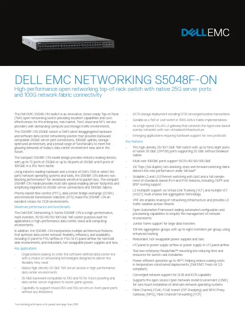
The Dell EMC S5048-ON switch is an innovative, future-ready T op-of-Rack (T oR) open networking switch providing excellent capabilities and cost-effectiveness for the enterprise, mid-market, Tier2 cloud and NFV service providers with demanding compute and storage traffic environments.The S5048F-ON 25GbE switch is Dell’s latest disaggregated hardware and software data center networking solution that provides backward compatible 25GbE server port connections, 100GbE uplinks, storage optimized architecture, and a broad range of functionality to meet the growing demands of today’s data center environment now and in the future.The compact S5048F-ON model design provides industry-leading density with up to 72 ports of 25GbE or up to 48 ports of 25GbE and 6 ports of 100GbE in a 1RU form factor.Using industry-leading hardware and a choice of Dell’s OS9 or select 3rd party network operating systems and tools, the S5048F-ON delivers non-blocking performance* for workloads sensitive to packet loss. The compact S5048F-ON model provides multi rate speed enabling denser footprints and simplifying migration to 25GbE server connections and 100GbE fabrics. Priority-based flow control (PFC), data center bridge exchange (DCBX) and enhanced transmission selection (ETS) make the S5048F-ON an excellent choice for DCB environments.Maximum performance and functionalityThe Dell EMC Networking S-Series S5048F-ON is a high-performance, multi-function, 10/25/40/50/100 GbE T oR switch purpose-built for applications in high-performance data center, cloud and computing environments.In addition, the S5048F-ON incorporates multiple architectural features that optimize data center network flexibility, efficiency, and availability, including IO panel to PSU airflow or PSU to IO panel airflow for hot/cold aisle environments, and redundant, hot-swappable power supplies and fans. Key applications• Organizations looking to enter the software-defined data center era with a choice of networking technologies designed to deliver theflexibility they need• Native high-density 25 GbE T oR server access in high-performance data center environments• 25 GbE backward compatible to 10G and 1G for future proofing and data center server migration to faster uplink speeds.• Capability to support mixed 25G and 10G servers on front panel ports • iSCSI storage deployment including DCB converged lossless transactions • Suitable as a T oR or Leaf switch in 100G Active Fabric implementations • As a high speed VXLAN L2 gateway that connects the hypervisor-based overlay networks with non-virtualized infrastructure• Emerging applications requiring hardware support for new protocols Key features• 1RU high-density 25/10/1 GbE T oR switch with up to forty eight ports of native 25 GbE (SFP28) ports supporting 25 GbE without breakout cables• Multi-rate 100GbE ports support 10/25/40/50/100 GbE• 3.6 Tbps (full-duplex) non-blocking, store and forward switching fabric delivers line-rate performance under full load*• Scalable L2 and L3 Ethernet switching with QoS and a full comple-ment of standards-based IPv4 and IPv6 features, including OSPF and BGP routing support• L2 multipath support via Virtual Link Trunking (VLT) and multiple VLT (mVLT) multi-chassis link aggregation technology• VRF-lite enables sharing of networking infrastructure and provides L3 traffic isolation across tenants• Open Automation Framework adding automated configuration and provisioning capabilities to simplify the management of networkenvironments• Jumbo frame support for large data transfers• 128 link aggregation groups with up to eight members per group, using enhanced hashing• Redundant, hot-swappable power supplies and fans• I/O panel to power supply airflow or power supply to I/O panel airflow • T ool-less enterprise ReadyRails™ mounting kits reducing time and resources for switch rack installation• Power-efficient operation up to 45°C helping reduce cooling costs in temperature-constrained deployments (Dell EMC Fresh Air 2.0compliant)• Converged network support for DCB and ECN capability• Supports the open source Open Network Install Environment (ONIE) for zero touch installation of alternate network operating systems• Fibre Channel, FCoE, FCoE transit (FIP Snooping) and NPIV ProxyDELL EMC NETWORKING S5048F-ONHigh-performance open networking top-of-rack switch with native 25G server ports and 100G network fabric connectivity**future deliverable48 line-rate 25 Gigabit Ethernet SFP28 ports6 line-rate 100 Gigabit Ethernet QSFP28 ports1 RJ45 console/management port with RS232signaling1 Micro-USB type B optional console port1 10/100/1000 Base-T Ethernet port used asmanagement port1 USB type A port for the external mass storage Size: 1 RU, 1.72 h x 17.1 w x 18” d(4.4 h x 43.4 w x 45.7 cm d)Weight: 22lbs (9.98kg)ISO 7779 A-weighted sound pressure level: 59.6 dBA at 73.4°F (23°C)Power supply: 100–240 VAC 50/60 HzMax. thermal output: 1956 BTU/hMax. current draw per system:5.73A/4.8A at 100/120V AC2.87A/2.4A at 200/240V ACMax. power consumption: 573 Watts (AC)T yp. power consumption: 288 Watts (AC) with all optics loadedMax. operating specifications:Operating temperature: 32° to 113°F (0° to 45°C) Operating humidity: 10 to 90% (RH), non-condensingFresh Air Compliant to 45°CMax. non-operating specifications:Storage temperature: –40° to 158°F (–40° to70°C)Storage humidity: 5 to 95% (RH), non-condensing RedundancyT wo hot swappable redundant power suppliesHot swappable redundant fansPerformanceSwitch fabric capacity: 3.6TbpsForwarding capacity: Up to 2,678 MppsPacket buffer memory: 22MB (16MB supported in initial release)CPU memory: 8GBMAC addresses: 132K (in scaled-l2-switch mode) ARP table: 82K (in scaled-l3-hosts mode)IPv4 routes: Up to 128KIPv6 routes: Up to 64K (20k currently supported) Multicast hosts: Up to 8KLink aggregation: 128 groups, 32 members per LAG groupLayer 2 VLANs: 4KMSTP: 64 instancesLAG Load Balancing: Based on layer 2, IPv4 or IPv6 header, or tunnel inner header contentsQoS data queues: 8QoS control queues: 12QoS: 1024 entries per TileIngress ACL: 1024 entries per TileEgress ACL: 1k entries per TilePre-Ingress ACL: 1k entries per TileIEEE Compliance802.1AB LLDP802.1D Bridging, STP802.1p L2 Prioritization802.1Q VLAN T agging, Double VLAN T agging,GVRP802.1Qbb PFC802.1Qaz ETS802.1s MSTP802.1w RSTP802.1X Network Access Control802.3ab Gigabit Ethernet (1000BASE-T) orbreakout802.3ac Frame Extensions for VLAN T agging 802.3ad Link Aggregation with LACP 802.3ba 40 Gigabit Ethernet (40GBase-SR4,40GBase-CR4, 40GBase-LR4, 100GBase-SR10, 100GBase-LR4, 100GBase-ER4) onoptical ports802.3bj 100 Gigabit Ethernet802.3u Fast Ethernet (100Base-TX) on mgmtports802.3x Flow Control802.3z Gigabit Ethernet (1000Base-X) with QSAANSI/TIA-1057 LLDP-MEDForce10 PVST+Jumbo MTU support 9,416 bytesLayer2 Protocols4301 Security Architecture for IPSec*4302 IPSec Authentication Header*4303 ESP Protocol*802.1D Compatible802.1p L2 Prioritization802.1Q VLAN T agging802.1s MSTP802.1w RSTP802.1t RPVST+802.3ad Link Aggregation with LACPVL T Virtual Link T runkingRFC Compliance768 UDP793 TCP854 T elnet959 FTP1321 MD51350 TFTP2474 Differentiated Services2698 T wo Rate Three Color Marker3164 Syslog4254 S SHv2General IPv4 Protocols791 I Pv4792 ICMP826 ARP1027 Proxy ARP1035 DNS (client)1042 Ethernet Transmission1191 Path MTU Discovery1305 NTPv41519 CIDR1542 BOOTP (relay)1858 IP Fragment Filtering2131 DHCP (server and relay)5798 V RRP3021 31-bit Prefixes3046 D HCP Option 82 (Relay)1812 Requirements for IPv4 Routers1918 Address Allocation for Private Internets2474 Diffserv Field in IPv4 and Ipv6 Headers2596 A ssured Forwarding PHB Group3195 Reliable Delivery for Syslog3246 E xpedited Assured Forwarding4364 V RF-lite (IPv4 VRF with OSPF and BGP)*General IPv6 Protocols1981 Path MTU Discovery*2460 I Pv62461 Neighbor Discovery*2462 S tateless Address AutoConfig2463 I CMPv62675 Jumbo grams3587 Global Unicast Address Format4291 IPv6 Addressing2464 T ransmission of IPv6 Packets over EthernetNetworks2711 IPv6 Router Alert Option4007 I Pv6 Scoped Address Architectureand Routers4291 IPv6 Addressing Architecture4861 Neighbor Discovery for IPv64862 I Pv6 Stateless Address Autoconfiguration5095 Deprecation of T ype 0 Routing Headers in IPv6IPv6 Management support (telnet, FTP, TACACS,RADI US, SSH, NTP)RIP1058 RIPv12453 R I Pv2OSPF (v2/v3)1587 NSSA (not supported in OSPFv3)1745 OSPF/BGP interaction1765 OSPF Database overflow2154 MD52328 OSPFv22370 Opaque LSA3101 OSPF NSSA3623 O SPF Graceful Restart (Helper mode)*BGP1997 Communities2385 M D52439 R oute Flap Damping2545 B GP-4 Multiprotocol Extensions for IPv6I nter-Domain Routing2796 Route Reflection2842 C apabilities2858 M ultiprotocol Extensions2918 Route Refresh3065 C onfederations4271 BGP-44360 E xtended Communities4893 4-byte ASN5396 4-byte ASN Representation5492 C apabilities AdvertisementMulticast1112 IGMPv12236 I GMPv23376 IGMPv3MSDPPIM-SMPIM-SSMNetwork Management1155 SMIv11157 SNMPv11212 Concise MIB Definitions1215 SNMP Traps1493 Bridges MIB1850 OSPFv2 MIB1901 Community-Based SNMPv22011 IP MIB2096 I P Forwarding T able MIB2578 SMI v22579 T extual Conventions for SMIv22580 C onformance Statements for SMIv22618 RADIUS Authentication MIB2665 E thernet-Like Interfaces MIB2674 Extended Bridge MIB2787 VRRP MIB2819 RMON MIB (groups 1, 2, 3, 9)2863 I nterfaces MIB3273 RMON High Capacity MIB3410 SNMPv33411 SNMPv3 Management Framework3412 Message Processing and Dispatching for theSimple Network Management Protocol (SNMP)3413 SNMP Applications3414 User-based Security Model (USM) forSNMPv33415 VACM for SNMP3416 SNMPv23417 Transport mappings for SNMP3418 SNMP MIB3434 R MON High Capacity Alarm MIB3584 C oexistance between SNMP v1, v2 and v3 4022 I P MIB4087 IP Tunnel MIB4113 UDP MIB4133 Entity MIB4292 M IB for IP4293 M IB for IPv6 T extual Conventions4502 R MONv2 (groups 1,2,3,9)5060 PIM MIBANSI/TIA-1057 LLDP-MED MIBDell_ITA.Rev_1_1 MIBdraft-ietf-idr-bgp4-mib-06 BGP MIBv1IEEE 802.1AB LLDP MIBIEEE 802.1AB LLDP DOT1 MIBIEEE 802.1AB LLDP DOT3 MIB sFlowv5 sFlowv5 MIB (version 1.3)DELL-NETWORKING-BGP4-V2-MIB(draft-ietf-idr-bgp4-mibv2-05)DELL-NETWORKING-IF-EXTENSION-MIBDELL-NETWORKING-LINK-AGGREGATION-MIB DELL-NETWORKING-COPY-CONFIG-MIBDELL-NETWORKING-PRODUCTS-MIBDELL-NETWORKING-CHASSIS-MIBDELL-NETWORKING-SMIDELL-NETWORKING-TCDELL-NETWORKING-TRAP-EVENT-MIBDELL-NETWORKING-SYSTEM-COMPONENT-MIB DELL-NETWORKING-FIB-MIBDELL-NETWORKING-FPSTATS-MIBDELL-NETWORKING-ISIS-MIBDELL-NETWORKING-FIPSNOOPING-MIBDELL-NETWORKING-VIRTUAL-LINK-TRUNK-MIB DELL-NETWORKING-DCB-MIBDELL-NETWORKING-OPENFLOW-MIBDELL-NETWORKING-BMP-MIBDELL-NETWORKING-BPSTATS-MIBSecuritydraft-grant-tacacs-02 TACACS+2404 The Use of HMACSHA-1-96 within ESP and AH 2865 R ADI US3162 Radius and IPv63579 RADIUS support for EAP3580 802.1X with RADIUS3768 EAP3826 A ES Cipher Algorithm in the SNMP User Base Security Model4250, 4251, 4252, 4253, 4254 SSHv24301 Security Architecture for IPSec4302 I PSec Authentication Header4807 IPsecv Security Policy DB MIBData center bridging802.1Qbb Priority-Based Flow Control802.1Qaz Enhanced Transmission Selection (ETS)* Data Center Bridging eXchange (DCBx)DCBx Application TLV (iSCSI, FCoE*) Regulatory complianceSafetyUL/CSA 60950-1, Second EditionEN 60950-1, Second EditionIEC 60950-1, Second Edition Including All National Deviations and Group DifferencesEN 60825-1 Safety of Laser Products Part 1: Equipment Classification Requirements and User’s GuideEN 60825-2 Safety of Laser Products Part 2: Safety of Optical Fibre Communication SystemsIEC 62368-1FDA Regulation 21 CFR 1040.10 and 1040.11 Emissions & ImmunityFCC Part 15 (CFR 47) (USA) Class AICES-003 (Canada) Class AEN55032: 2015 (Europe) Class ACISPR32 (International) Class AAS/NZS CISPR32 (Australia and New Zealand) Class AVCCI (Japan) Class AKN32 (Korea) Class ACNS13438 (T aiwan) Class ACISPR22EN55022EN61000-3-2EN61000-3-3EN61000-6-1EN300 386EN 61000-4-2 ESDEN 61000-4-3 Radiated ImmunityEN 61000-4-4 EFTEN 61000-4-5 SurgeEN 61000-4-6 Low Frequency Conducted Immunity NEBSGR-63-CoreGR-1089-CoreATT-TP-76200VZ.TPR.9305RoHSRoHS 6 and China RoHS compliantCertificationsJapan: VCCI V3/2009 Class AUSA: FCC CFR 47 Part 15, Subpart B:2009, Class A Warranty1 Year Return to DepotLearn more at /NetworkingIT Lifecycle Servicesfor NetworkingExperts, insights and easeOur highly trained experts, withinnovative tools and proven processes,help you transform your IT investments into strategic advantages.Plan & DesignLet us analyze yourmultivendor environmentand deliver a comprehensivereport and action plan to buildupon the existing network andimprove performance.Deploy & IntegrateGet new wired or wirelessnetwork technology installedand configured with ProDeploy.Reduce costs, save time, andget up and running fast.EducateEnsure your staff builds theright skills for long-termsuccess. Get certified on DellEMC Networking technologyand learn how to increaseperformance and optimizeinfrastructure.Manage & SupportGain access to technical expertsand quickly resolve multivendornetworking challenges withProSupport. Spend less timeresolving network issues andmore time innovating.OptimizeMaximize performance fordynamic IT environments withDell EMC Optimize. Benefitfrom in-depth predictiveanalysis, remote monitoringand a dedicated systemsanalyst for your network.RetireWe can help you resell or retireexcess hardware while meetinglocal regulatory guidelines andacting in an environmentallyresponsible way.Learn more at/lifecycleservices*Future release**Packet sizes over 147 Bytes。
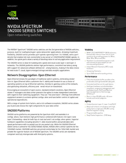
Visibility>WHAT JUST HAPPENED?® (WJH) telemetry dramatically reduces mean time to issue resolution by providing answers to: When, What, Who, Where and Why >Hardware-accelerated histograms track and summarize queue depths at sub-microsecond granularity >Inband Network Telemetry (INT)-ready hardware >Streaming Telemetry>Up to 256K shared forwarding entriesPerformance>Fully shared packet buffer provides a fair, predictable and high bandwidth data path >Consistent and low cut-through latency >Intelligent hardware-accelerated data movement, congestion management and load balancing for RoCE and Machine learning applications that leverage GPUDirect ® >Best-in-class VXLAN scale—6X more tunnels and tunnel endpointsAgility>Comprehensive Layer-2, Layer-3 and RoCE >Advanced network virtualization with high performance single pass VXLAN routing and IPv6 segment routing >Programmable pipeline>Deep Packet Inspection – 512B deepThe NVIDIA ® Spectrum ™ SN2000 series switches are the 2nd generation of NVIDIA switches, purpose-built for leaf/spine/super-spine datacenter applications. Allowing maximum fl exibility, SN2000 series provides port speeds spanning from 1 to 100GbE, with a port density that enables full rack connectivity to any server at 1/20/25/40/50/100GbE speeds. In addition, the uplink ports allow a variety of blocking ratios to suit any application requirement.The SN2000 series is ideal for building wire-speed and cloud-scale layer-2 and layer-3 networks. The SN2000 platforms deliver high performance, consistent low latency along with support for advanced software defined net orking features, making it the ideal choice for web scale IT, cloud, hyperconverged storage and data analytics applications.Network Disaggregation: Open EthernetOpen Ethernet breaks the paradigm of traditional switch systems, eliminating vendor lock-in. Open Ethernet offers customers the fl xibility and freedom to use a choice of operating systems on top of Ethernet switches, thereby re-gaining control of the network, and optimizing utilization, efficiency and verall return on investment.Encouraging an ecosystem of open source, standard network solutions, Open Ethernet allows IT managers and data center planners the option to make independent selections with regard to their switching equipment. They can “mix and match” offerings from different equipment vendors to achieve optimal configu ation and have better control of capital and operational expenditures.With a range of system form factors, and a rich software ecosystem, SN2000 series allows you to pick and choose the right components for your data center .SN2000 PlatformsSN2000 series platforms are powered by the Spectrum ASIC and available in 4configu ations. Each delivers high performance combined with feature-rich layer 2 and layer 3 forwarding—ideal for both top-of-rack leaf and fi ed configu ation spines. Superior hardware capabilities including dynamic fl xible shared buffers and predictable wire speed performance with no packet loss for any packet size. While the SN2000 Ethernet switch series is aimed for the 25/50/100GbE market, NVIDIA offers similar systems for the 10/40GbE market: SN2000B switches are priced comfortably for the 10/40 GbE market and provide the superior feature set of NVIDIA Spectrum. The SN2000 series are standards compliant and fully interoperable with third party systems.NVIDIA SPECTRUMSN2000 SERIES SWITCHESOpen networking switchesDATASHEETSN2700The SN2700 carries a huge throughput of 3.2Tb/s, 32 ports at 100GbE, with a landmark4.76Bpps processing capacity in a compact 1RU form factor . With port speeds spanning from 1 to 100GbE per port and a wide choice of QSFP transceivers and cables support. NVIDIA SN2700 supports flat la ency of 300ns in cut-through mode, and a shared 16MB packet buffer pool that is allocated dynamically to ports that are congested.SN2410The SN2410 has 8 ports running at 100GbE (can be split to 16 ports running 50GbE) and 48 ports running at 25GbE, carrying a throughput of 2Tb/s with a 2.97Bpps processing capacity in a compact 1RU form factor . The SN2410 switch is an ideal top-of-rack (ToR) solution, allowing maximum fl xibility, with port speeds spanning from 10GbE to 100GbE per port. Its optimized port configu ation enables high-speed rack connectivity to any server at 10 or 25GbE speeds. The 100GbE uplink ports allow a variety of blocking ratios that suit any application requirement.SN2100The SN2100 carries a unique design to accommodate the highest rack performance. Its design allows side-by-side placement of two switches in a single 1RU slot of a 19” rack, delivering high availability to the hosts. The SN2100 accommodates 16 ports running at 100GbE, with throughput of 1.6Tb/s and a 2.38Bpps processing capacity.SN2010The SN2010 switch is the ideal top of rack (ToR) solution for small hyper-converged and storage deployments. Packed with 18 ports of 10/25GbE and 4 ports of 40/100GbE, theSN2010 can deliver up to 850GbE with 1.26Bpps processing capacity in a compact half width 1RU form factorPlatform Software Options>The SN2000 series platforms are factory available in three differen t fl avors:>Pre-installed with NVIDIA Cumulus Linux ™, a revolutionary operating system that takes the Linux user experience from servers to switches, and provides a rich routing functionality for large scale applications.>Pre-installed with NVIDIA Onyx ™, a home-grown operating system, with a classic CLI interface.>Bare metal including ONIE image, installable with any ONIE-mounted OS.ONIE-based platforms utilize the advantages of Open Networking and the SpectrumASIC capabilities.Linux SwitchHigh Availability>NVIDIA SN2000 series switches were designed for high availability from both asoftware and hardware perspective.Key high availability features include:>1+1 hot-swappable power supplies and four N+1 hot-swap fans(supported on SN2700 and SN2410)>Color coded PSUs and fans>Up to 64 1/10/25/40/50/100GbE ports per link aggregation group>Multi-chassis LAG for active/active L2 multipathing>64-way ECMP routing for load balancing and redundancySN2000 Series: A Rich Software EcosystemCumulux-LinuxNVIDIA Cumulus Linux is a powerful open network operating system enabling advanced automation, customization and scalability using web-scale principles like the world’s largest data centers. It accelerates networking functions and provides choice from an extensive list of supported switch models including NVIDIA Spectrum based switches. Cumulus Linux was built for automation, scalability an d fl exibility, allowing you to build data center and campus networks that ideally suits your business needs. Cumulus Linux is the only open network OS that allows you to build affordable and ef fi cient network operations like the world’s largest data center operators, unlocking web-scale networking for businesses of all sizes.OnyxOnyx is a high performance switch operating system, with a classic CLI interface. Whether building a robust storage fabric, cloud, fi ancial or media and entertainment fabric, customers can leverage th e fl exibility of Onyx to tailor their network platform to their environment. With built-in work fl ow automation, monitoring and visibility tools, enhanced high availability mechanisms, and more, Onyx simpli fi es network processes andwork fl ows, increasing ef fi ciencies and reducing operating expenses and time-to-service.Microsoft SONiCSONiC was designed for cloud networking scenarios, where simplicity and managing at scale are the highest priorities. NVIDIA fully supports the Pure Open Source SONiC from the SONiC community site on all of the SN2000 series switch platforms. With advanced monitoring and diagnostic capabilities, SONiC is a perfec t fi t for the NVIDIA SN2000 series. Among other innovations, SONiC on SN2000 series enable s fi ne-grained failure recovery and in-service upgrades (ISSU), with zero downtime.DOCKER ContainersNVIDA fully supports the running of third party containerized applications on the switch system itself. The third party application has complete access to the bare-metal switch via its direct access to the SDK. The switch has tight controls over the amount of memory and CPU cycles each container is allowed to use, along wit h fi ne grained monitoring of those resources.Docker Containers SupportONIEThe Open Network Install Environment (ONIE) is an open compute project open source initiative driven by a community to de fi ne an open “install environment” for bare metal network switches, such as the Spectrum SN2000 series.ONIE enables a bare metal network switch ecosystem where end users have a choice of different network operating systems.Llinux Switch and DentLinux Switch enables users to natively install and use any standard Linux distributionas the switch operating system, such as DENT, a Linux-based networking OS stack that is suitable for campus and remote networking. Linux Switch is based on a Linux kernel driver model for Ethernet switches (Switchdev). It breaks the dependency of using vendor-speci fi c, closed-source software development kits. The open-source Linux driver is developed and maintained in the Linux kernel, replacing proprietary APIs with standard Linux kernel interfaces to control the switch hardware. This allows off-the-shelf Linux-based networking applications to operate on NVIDIA Spectrum-based switches for L2 switching and L3 routing, including open source routing protocol stacks, such as FRR (Quagga), Bird and XORP, OpenFlow applications, or user-speci fi c implementations. Cumulus NetQNVIDIA® Cumulus NetQ™ is a highly-scalable, modern, network operations tool set that provides visibility, troubleshooting and lifecycle management of your open networks in real time. NetQ delivers actionable insights and operational intelligence about the health of your data center and campus networks — from the container or host, all the way to the switch and port, enabling a NetDevOps approach. NetQ is the leading network operations tool that utilizes telemetry for deep troubleshooting, visibility and automated work fl ows from a single GUI interface, reducing maintenance and network downtimes. With the addition of full lifecycle management functionality, NetQ now combines the ability to easily upgrade, con fi gure and deploy network elements with a full suite of operations capabilities, such as visibility, troubleshooting, validation, trace and comparative look-back functionality.Build your Cloud Without CompromiseGroundbreaking PerformancePacket buffer architecture has a major impact on overall switch performance.The Spectrum packet buffer is monolithic and fully shared across all ports, supporting cut-through line rate traf fi c from all ports, without compromising scale or features. With its fast packet buffer, Spectrum is able to provide a high performance fair and bottleneck-free data path for mission-critical applications.Pervasive VisibilitySpectrum provides deep and contextual network visibility, which enables network operators to proactively manage issues and reduce mean time to recovery or innocence. WJH leverages the underlying silicon and software capability to provide granular and event-triggered information about infrastructure issues. In addition, the rich telemetry information from Spectrum is readily available via open APIs that are integratable with third party software tools and work fl ow engines.Unprecedented AgilityFor modern data center infrastructure to be software de fi ned and agile, both its compute and network building blocks need to be agile. Spectrum features a unique feature rich and ef fi cient packet processing pipeline that offers rich data center network virtualization features without compromising on performance or scale. Spectrum has a programmable pipeline and a deep packet parser/editor that can process payloads up to th e fi rst 512B. Spectrum supports single pass VXLAN routing as well as bridging.Massive ScaleThe number of endpoints in the data center is increasing exponentially. With the current shift from virtual machine-based architectures to container-based architectures, the high-scale forwarding tables required by modern data centers and mega-clouds increase by up to an order of magnitude or more. To answer the needs for scalability an d fl exibility, Spectrum uses intelligent algorithms and ef fi cient resource sharing, and supports unprecedented forwarding table, counters and policy scale.End-to-End 100 GbE SolutionThe SN2000 is part of NVIDIA complete end-to-end solutions providing 10 through 100GbE interconnectivity within the data center. Other devices in this solution include ConnectX®network interface cards and LinkX® copper or fi er cabling.SpecificationsSupported Transcievers and CablesWarranty InformationNVIDIA SN2000 series switches come with a one-year limited hardware return-and-repair warranty, with a 14 business day turnaround after the unit is received. For more information, please visit the NVIDIA Technical Support User Guide. Support services including next business day and 4-hour technician dispatch are available. For more information, please visit the NVIDIA Technical Support User Guide. NVIDIA offers installation, con fi guration, troubleshooting and monitoring services, available on-site or remotely delivered. For more information, please visit the NVIDIA Global Services website.Ordering InformationFor ordering information, please contact *************。
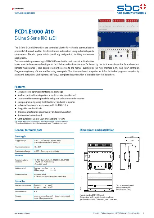
PCD1.E1000-A10E-Line S-Serie RIO 12DIData sheetGeneral technical dataPower supply On a 35 mm top-hat rail ( i n accordance with DIN EN 60715 TH35)Dimensions and installationThe S-Serie E-Line RIO modules are controlled via the RS-485 serial communication protocols S-Bus and Modbus for decentralised automation using industrial quality components. The data point mix is specifically designed for building automation applications.The compact design according to DIN 43880 enables the use in electrical distributionboxes even in the most confined spaces. Installation and maintenance are facilitated by the local manual override for each output. Remote maintenance is also possible using the access to the manual override by the web interface in the Saia PCD® controller. Programming is very efficient and fast using a complete FBox library with web templates for S-Bus. Individual programs may directly access the data points via Registers and Flags, a complete documentation is available from this data sheet.f S-Bus protocol optimized for fast data exchangef Modbus protocol for integration in multi-vendor installations*f Local override operating level via web panel or buttons on the module f Easy programming using the FBox library and web templates f Industrial hardware in accordance with IEC EN 61131-2 f Pluggable terminal blocksf Bridge connectors for power supply and communication f Bus termination on boardf Configurable Bi-Colour LEDs and labelling for I/Os* B y default the module is working in S-Bus Data Mode with Autobaud detection. To configure Modbus the Windows based Application “E-LineApp” is required.FeaturesHousing width 6 HP (105 mm)Compatible with electrical control cabinet (in accordance with DIN 43880, size 2 × 55 mm)/DA+DB-GND+24VOpenClose For easy installation the power supply and communicationbus is available together at one connector. The push-in springterminals enable wiring as well support the connector bridge.Push-in spring terminals enable wiring with rigid or flexible wireswith a diameter up to 1.5 mm². A max. of 1 mm² is permitted withcable end sleeves.Terminal technologyConnection conceptOFF No PowerGreen Communication OKGreen blink Auto bauding in progressOrange No communicationRed ErrorRed/Green alternate B ooter mode(e.g. during Firmware download)Red blink Internal fatal errorStatus LEDThe module provides an active bus termination. It is switchedoff by factory default. To enable the termination, the switchneed to be in the “Close” position.Bus terminationThe USB interface provides access to the communicationprotocol configuration. Firmware updates can also be downloaded via Saia PG5® Firmware Download tool.Service interfaceReset buttonPushed over 20 seconds: The button needs to be pushed forminimum 20 seconds and released during the first minute afterpower up. All user settings are reset to factory default values.Pushed at power up: Power off the device and press thebutton. Power on and release the button before 5 seconds havepassed. The device stays in boot mode for further actions likefirmware download etc.Input/output configurationAssignment overview OFF No Power Green Communication OK Green blink Auto bauding in progress Orange No communication Red Error Red/Green alternate B ooter mode(e.g. during Firmware download)Red blink Internal fatal errorStatus LEDLED SignalisationThe Input indication LED can be configured in colour and blink code separately for state Low and High. LED colour f Off f Red f Green*f Orange (red + green)LED blink code f No blink*f Slow blinking (0.5 flashes per second) f Fast blinking (2 flashes per second)*Factory defaultRemarks: I n case of error on analogue I/O (overflow), the LEDwill blink at 1 Hz.Digital intputf Data exchange for I/O via optimised S-Busf Configurable save state for bus interruption or timeout f Direct generation of the symbolsf Reading and writing of the status of the manual override status f Direct compatibility with web macrosThe modules are addressed and programmed with Saia PG5® Fupla FBoxes. Web templates are available for the operation and visualisation of the manual override function.Further information, including which FBoxes are supported,Getting Started, etc., can be found on our support page .Web templates are available for the operation and visualisation of the manual override function.FuplaCommunication FBoxWeb templatesProgrammingThe inputs of the E-Line RIO modules can be addressed via the standard S-Bus. However the FBoxfrom the E-Line library is used for the configuration of these modules.It is therefore recommended to use the optimised S-Bus protocol and the corresponding FBoxes from the E-Line library. Mixed mode operation is not recommended.Power supply and bus terminationConnection diagramsGND +24V/DA+DB–GND +24V/DA+DB–Digital inputs24 VDCSource operationE-Line libraryE-Line RIOs support the device setup by a windows application program connected via USB. The installer is available for down-load from the SBC support page: E-Line RIO IO Modules.The Baudrate can be defined as automatic detection (default) or set to a specific value. The drop down choice will be available when the check box “Automatic” is unchecked.TN delay and TS delay shall be left at their default values of 2.Create a new device configurationOpen an existing device configurationSave the current settings as device configurationUpload configuration from the deviceDownload settings to the deviceThe station number can be set by the rotary switches at the device in the range of 0 … 98. If the rotary switches are set to position 99 the station number can be defined by the deviceconfiguration in a range of 0 … 253.The serial communication protocol can be defined either as S-Bus or Modbus. By default the modules are delivered fromfactory with S-Bus.S-Bus settingsThe Baudrate is set by default to 115k. It can be defined aschoice of the list.For best interoperability the Parity Mode and number ofStop Bits can also be set.Modbus settingsS-Bus communication is based on Saia PCD® S-Bus Data Mode. Only the set-up of a unique S-Bus address within the communi-cation line is required to establish a communication between Saia PCD® controllers and E-Line RIO modules. The address can be set by the rotary switches at the front of the module. The baud rate will be learned from the network by factory default. In addition a Windows based application is available for manual parameter setup. Configuration parameters as well as manual override state and value are saved non-volatile. A delay of about one second between a manual state change and none volatile saving has to be taken into consideration.Device address f 0 … 98 Address is taken from the rotary switchesf 99Address is taken from the device configuration. The address is settable with the E-Line configuration software.Usage of the E-Line module specific FBoxesThe usage of the E-Line module specific FBoxes from the E-Line S-Bus Fupla library allows an easy and efficient commissioning of the E-Line RIO.The FBox allow to define and configure all possible functionalities of the E-Line RIO like the behaviour and colour of the LED’s and so on.In the background, the FBox does use the fast ‘E-Line S-Bus’ protocol for a high speed communication between the master and the RIO.The following chapter describes the media and parameter mapping to Registers and Flags for individual programming. For efficient PCD programming the E-Line RIO FBox family and templates are suitable for most applications. Only individual pro-gramming (e.g. Instruction List) require standard S-Bus communication.Digital inputsThe LEDs can be configured individually depending on the I/O state in colour and blink code.LED ConfigurationRegister format:Bit 0 ... 7 I/O state Low LED colour Bit 8 ... 15 I/O state Low LED blink code Bit 16 ... 23 I/O state High LED colour Bit 24 (31)I/O state High LED blink codeLED colour 0: Off1: Red2: G reen 3: Orange (red + green)LED blink code 0: No blink 1: Slow blinking (0.5 flashes per second) 2: Fast blinking (2 flashes per second)Factory default: Low: off, High: LED colour 2 (green), no blinkDirect access to the RIO media with standard S-Bus send and receive telegrams** Time in 0.1 ms (e.g. 2 means 200 us) before sending the first character after line driver activation (only used for S-Bus slave protocol)*** The four registers contain the ASCII characters of the product type.E.g. for PCD1.A2000-A20:0605: 50434431H 0606: 2E413230H 0607: 30302D41H 0608: 32300000HDevice InformationModbus fulfils the requirements for standard communication protocols. It is based on Modbus RTU. The Windows based configuration software is required to enable and set up the Modbus communication parameters. The device address can be set up with the rotary switches at the front of the module. Configuration parameters as well as manual override state and value are saved non-volatile. A delay of about one second between a manual state change and non-volatile saving has to be taken into consideration.Device addressf0 … 98 Address is taken from the rotary switchesf99 A ddress is taken from the device configuration. The address is settable with the E-Line configuration software.Start-up proceduref Reboot: All outputs are cleared (Off state)f<1 sec. Output in manual operation are set according to the state before power down.f Outputs in automatic modeIs no telegram received after reboot within the “safe state power-on timeout” the module enters as will intothe safe state mode and sets the outputs according to their configured values.On reception of a valid command telegram the outputs are controlled by the communication. When nocommunication update followed within the “safe state com. timeout” the module enters into safe state andsets the outputs according to their configured values.The following chapter describes the media and parameter mapping to Registers and Flags (=Coils).Supported Modbus services:f Function code 1 (read outputs)f Function code 3 (read registers)f Function code 15 (write multiple outputs)f Function code 16 (write multiple registers)The CRC has to be calculated over all telegram bytes starting with address field up to the last data byte. The CRC has to be attached to the data. Please find an example at the appendix of this document. For more details, please refer the publicly available Modbus documentation .The LEDs can be configured individually depending on the I/O state in colour and blink code.Register format:Output L, Bit 0 … 7 I/O state Low LED colour Output L, Bit 8 … 15 I/O state Low LED blink code Output H, Bit 0 … 7 I/O state High LED colourOutput H, Bit 8 … 15 I/O state High LED blink codeLED colour 0: Off1: Red2: Green3: Orange (red + green)LED blink code 0: No blink1: Slow blinking (0.5 flashes per second)2: Fast blinking (2 flashes per second)Factory default: Low: off, High: LED colour 2 (green), no blinkE.g. for PCD1.A2000-A20:1210…1217: 5043H | 4431H | 2E41H | 3230H | 3030H | 2D41H | 3230H | 0000HDevice InformationCRC Generation Example(Source: /docs/PI_MBUS_300.pdf, the following content of this page is copied from the referenced document. In case of any questions, please check out the original source)The function takes two arguments: unsigned char *puchMsg; A pointer to the message buffer containing binary data to be used for generating the CRC unsigned short usDataLen; The quantity of bytes in the message buffer. The function returns the CRC as a type unsigned short.CRC Generation Functionunsigned short CRC16(puchMsg, usDataLen) ;unsigned char *puchMsg ; /* message to calculate CRC upon */unsigned short usDataLen ; /* quantity of bytes in message */{unsigned char uchCRCHi = 0xFF ; /* high byte of CRC initialized */unsigned char uchCRCLo = 0xFF ; /* low byte of CRC initialized */unsigned uIndex ; /* will index into CRC lookup table */while (usDataLen--) /* pass through message buffer */{uIndex = uchCRCHi ^ *puchMsgg++; /* calculate the CRC */uchCRCHi = uchCRCLo ^ auchCRCHi[uIndex];uchCRCLo = auchCRCLo[uIndex];}return (uchCRCHi << 8 | uchCRCLo);}High-Order Byte Table/* Table of CRC values for high-order byte */static unsigned char auchCRCHi[] = {0x00, 0xC1, 0x81, 0x40, 0x01, 0xC0, 0x80, 0x41, 0x01, 0xC0, 0x80, 0x41, 0x00, 0xC1, 0x81, 0x40,0x01, 0xC0, 0x80, 0x41, 0x00, 0xC1, 0x81, 0x40, 0x00, 0xC1, 0x81, 0x40, 0x01, 0xC0, 0x80, 0x41,0x01, 0xC0, 0x80, 0x41, 0x00, 0xC1, 0x81, 0x40, 0x00, 0xC1, 0x81, 0x40, 0x01, 0xC0, 0x80, 0x41,0x00, 0xC1, 0x81, 0x40, 0x01, 0xC0, 0x80, 0x41, 0x01, 0xC0, 0x80, 0x41, 0x00, 0xC1, 0x81, 0x40,0x01, 0xC0, 0x80, 0x41, 0x00, 0xC1, 0x81, 0x40, 0x00, 0xC1, 0x81, 0x40, 0x01, 0xC0, 0x80, 0x41,0x00, 0xC1, 0x81, 0x40, 0x01, 0xC0, 0x80, 0x41, 0x01, 0xC0, 0x80, 0x41, 0x00, 0xC1, 0x81, 0x40,0x00, 0xC1, 0x81, 0x40, 0x01, 0xC0, 0x80, 0x41, 0x01, 0xC0, 0x80, 0x41, 0x00, 0xC1, 0x81, 0x40,0x01, 0xC0, 0x80, 0x41, 0x00, 0xC1, 0x81, 0x40, 0x00, 0xC1, 0x81, 0x40, 0x01, 0xC0, 0x80, 0x41,0x01, 0xC0, 0x80, 0x41, 0x00, 0xC1, 0x81, 0x40, 0x00, 0xC1, 0x81, 0x40, 0x01, 0xC0, 0x80, 0x41,0x00, 0xC1, 0x81, 0x40, 0x01, 0xC0, 0x80, 0x41, 0x01, 0xC0, 0x80, 0x41, 0x00, 0xC1, 0x81, 0x40,0x00, 0xC1, 0x81, 0x40, 0x01, 0xC0, 0x80, 0x41, 0x01, 0xC0, 0x80, 0x41, 0x00, 0xC1, 0x81, 0x40,0x01, 0xC0, 0x80, 0x41, 0x00, 0xC1, 0x81, 0x40, 0x00, 0xC1, 0x81, 0x40, 0x01, 0xC0, 0x80, 0x41,0x00, 0xC1, 0x81, 0x40, 0x01, 0xC0, 0x80, 0x41, 0x01, 0xC0, 0x80, 0x41, 0x00, 0xC1, 0x81, 0x40,0x01, 0xC0, 0x80, 0x41, 0x00, 0xC1, 0x81, 0x40, 0x00, 0xC1, 0x81, 0x40, 0x01, 0xC0, 0x80, 0x41,0x01, 0xC0, 0x80, 0x41, 0x00, 0xC1, 0x81, 0x40, 0x00, 0xC1, 0x81, 0x40, 0x01, 0xC0, 0x80, 0x41,0x00, 0xC1, 0x81, 0x40, 0x01, 0xC0, 0x80, 0x41, 0x01, 0xC0, 0x80, 0x41, 0x00, 0xC1, 0x81, 0x40 }; Low-Order Byte Table/* Table of CRC values for low-order byte */static char auchCRCLo[] = {0x00, 0xC0, 0xC1, 0x01, 0xC3, 0x03, 0x02, 0xC2, 0xC6, 0x06, 0x07, 0xC7, 0x05, 0xC5, 0xC4, 0x04,0xCC, 0x0C, 0x0D, 0xCD, 0x0F, 0xCF, 0xCE, 0x0E, 0x0A, 0xCA, 0xCB, 0x0B, 0xC9, 0x09, 0x08, 0xC8,0xD8, 0x18, 0x19, 0xD9, 0x1B, 0xDB, 0xDA, 0x1A, 0x1E, 0xDE, 0xDF, 0x1F, 0xDD, 0x1D, 0x1C, 0xDC,0x14, 0xD4, 0xD5, 0x15, 0xD7, 0x17, 0x16, 0xD6, 0xD2, 0x12, 0x13, 0xD3, 0x11, 0xD1, 0xD0, 0x10,0xF0, 0x30, 0x31, 0xF1, 0x33, 0xF3, 0xF2, 0x32, 0x36, 0xF6, 0xF7, 0x37, 0xF5, 0x35, 0x34, 0xF4,0x3C, 0xFC, 0xFD, 0x3D, 0xFF, 0x3F, 0x3E, 0xFE, 0xFA, 0x3A, 0x3B, 0xFB, 0x39, 0xF9, 0xF8, 0x38,0x28, 0xE8, 0xE9, 0x29, 0xEB, 0x2B, 0x2A, 0xEA, 0xEE, 0x2E, 0x2F, 0xEF, 0x2D, 0xED, 0xEC, 0x2C,0xE4, 0x24, 0x25, 0xE5, 0x27, 0xE7, 0xE6, 0x26, 0x22, 0xE2, 0xE3, 0x23, 0xE1, 0x21, 0x20, 0xE0,0xA0, 0x60, 0x61, 0xA1, 0x63, 0xA3, 0xA2, 0x62, 0x66, 0xA6, 0xA7, 0x67, 0xA5, 0x65, 0x64, 0xA4,0x6C, 0xAC, 0xAD, 0x6D, 0xAF, 0x6F, 0x6E, 0xAE, 0xAA, 0x6A, 0x6B, 0xAB, 0x69, 0xA9, 0xA8, 0x68,0x78, 0xB8, 0xB9, 0x79, 0xBB, 0x7B, 0x7A, 0xBA, 0xBE, 0x7E, 0x7F, 0xBF, 0x7D, 0xBD, 0xBC, 0x7C,0xB4, 0x74, 0x75, 0xB5, 0x77, 0xB7, 0xB6, 0x76, 0x72, 0xB2, 0xB3, 0x73, 0xB1, 0x71, 0x70, 0xB0,0x50, 0x90, 0x91, 0x51, 0x93, 0x53, 0x52, 0x92, 0x96, 0x56, 0x57, 0x97, 0x55, 0x95, 0x94, 0x54,0x9C, 0x5C, 0x5D, 0x9D, 0x5F, 0x9F, 0x9E, 0x5E, 0x5A, 0x9A, 0x9B, 0x5B, 0x99, 0x59, 0x58, 0x98,0x88, 0x48, 0x49, 0x89, 0x4B, 0x8B, 0x8A, 0x4A, 0x4E, 0x8E, 0x8F, 0x4F, 0x8D, 0x4D, 0x4C, 0x8C,0x44, 0x84, 0x85, 0x45, 0x87, 0x47, 0x46, 0x86, 0x82, 0x42, 0x43, 0x83, 0x41, 0x81, 0x80, 0x40 };PCD1.K0206-005PCD1.K0206-025PCD1.E1000-A10Saia-Burgess Controls AGBahnhofstrasse 18 | 3280 Murten, Switzerland T +41 26 580 30 00 | F +41 26 580 34 ********************|* Horizontal pitch: 1 HP corresponds to 17.5 mmTerminal set 32304321-003-S。

TETRA AND LTE WORKING TOGETHERThe MTS4L TETRA/LTE Base Stationprovides a flexible path for the addition of LTE to complement a TETRA system. By provisioning for the addition of an eNodeB into the TETRA Base Station cabinet, Motorola is offering a highly flexible migration solution for TETRA operators. The MTS4L can be installed as a TETRA only base station, but it can include the services for the eNodeB such as shared backhaul, common power supply and battery backup. These services can be installed at the start or they can be upgraded at a later time when needed by customers. Most importantly the MTS4L footprint is unchanged when the eNodeB is installed and so the upgrade is very simple and fast.MTS4 TETRA BTS IN THE MTS4L CABINET DESIGNED FOR THE FUTUREBuilt and designed for future communications needs, the MTS4 supports TETRA Enhanced Data Services (TEDS) - the platform for secure mission critical high speed data services.Providing support for E1 and IP-over-Ethernet, the MTS4enables operators to utilize the most efficient andcost effective transmission networking technologiesavailable today and in the future.FLEXIBLE CAPACITY AND COVERAGEThe compact MTS4 is a high performance base stationwith state of the art capacity and coverage enhancingcapabilities:• C-SCCH – additional control channels on the maincarrier, quadrupling existing capacity.• B est-in-class transmitter output power and receiversensitivity, together with various diversity options,enabling a reduction in the number of sites requiredto achieve a given level of coverage, and increaseddata performance and enhanced audio quality.•Rx/Tx antenna, easing implementation costs andreducing cycle time.MTS4 ADDITIONAL FEATURES• P rovision for eNode B in the samecabinet as the TETRA BTS• R apid installation of eNobe B asa future upgrade with minimumcost and disruption•frequency and roll-out whenappropriate• I nterference Detection andCorrection• Air Interface Encryption• M ulti-Slot Packet Data (MSPD)for enhanced data services• Hot swapable modules• D ynamic Channel allocationbetween voice and packet data• L ockable door equipped withstandard alarm contacts – aneffective intrusion detectionsystem.MOTOROLA, MOTO, MOTOROLA SOLUTIONS and the Stylized M Logo are trademarks or registered trademarks of Motorola Trademark Holdings, LLC and are used under license.All other trademarks are the property of their respective owner shown are typical.To learn more, visit us on the web at: /TETRAOPTIMISED TOTAL COST OF OWNERSHIPThe running costs of basestation sites typically account for a significant portion of the total cost of ownership of any TETRA network. MTS4 basestations are specifically designed with advanced features that help to minimise operational expenditures. Such features enable:• B etter power consumption through use of high delivering significant operational cost savings over the network’s lifetime.• R educed transmission costs – native support using IP-over-Ethernet capability means that the MTS4 can enable up to 70% savings compared with non-IP based transmission.• R educed battery capacity requirement and low heat dissipation due to excellent power efficiency. With a strong integrated battery charger, power supply costs are kept to an absolute minimum.RELIABLE AND EASY TO MAINTAINThe MTS4 offers supreme reliability plus flexible access for easy servicing. Key features include:• T wo E1 or Ethernet interfaces can be provided with the MTS4 to facilitate implementing link redundancy using ring configurations. Redundant E1 and Ethernet ports can be activated in the event of link failure, ensuring continuous connectivity.• L ocal Site Trunking – in the event of site link failure, the base station is able to operate independent of themobile switching office, maintaining secure talkgroup communications throughout.• N on-GPS operation – supports operation in the absence of a GPS signal, ideally suited to underground applications.• F ull redundancy of site controller and base radio subsystems including support for automatic Main Control Channel switching.TOTALLY SECURE…DAY AND NIGHTWith the MTS4, there is no need to worry about theft or vandalism. The basestation equipment includes the latest security features for total peace of mind:• E xternal alarm interface supports 15 alarm inputs and 2 external control outputs.• T he MTS4L supports site link encryption in release 8.1, and air interface encryption with TEA1, TEA2 and TEA3.© 2014 Motorola Solutions, Inc. All rights reserved.。
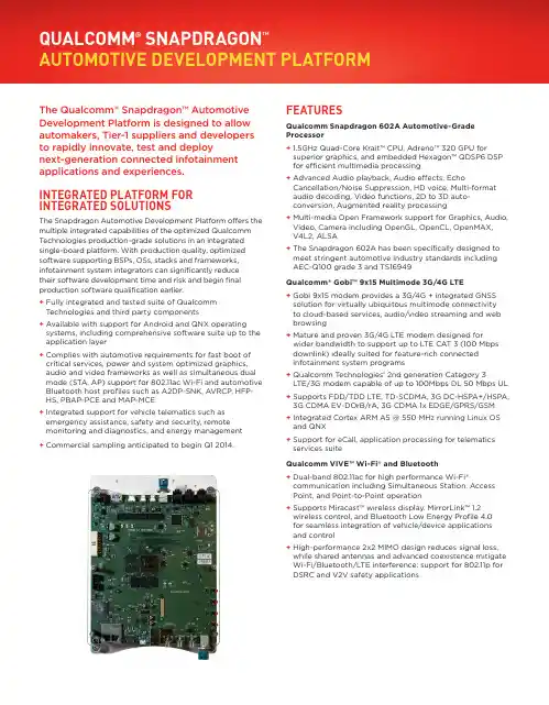
The Qualcomm® Snapdragon™ Automotive Development Platform is designed to allow automakers, Tier-1 suppliers and developers to rapidly innovate, test and deploynext-generation connected infotainment applications and experiences. INTEGRATED PLATFORM FOR INTEGRATED SOLUTIONSThe Snapdragon Automotive Development Platform offers the multiple integrated capabilities of the optimized Qualcomm Technologies production-grade solutions in an integrated single-board platform. With production quality, optimized software supporting BSPs, OSs, stacks and frameworks, infotainment system integrators can significantly reducetheir software development time and risk and begin final production software qualification earlier.+ Fully integrated and tested suite of QualcommT echnologies and third party components+ Available with support for Android and QNX operating systems, including comprehensive software suite up to the application layer+ Complies with automotive requirements for fast boot of critical services, power and system optimized graphics, audio and video frameworks as well as simultaneous dual mode (STA, AP) support for 802.11ac Wi-Fi and automotive Bluetooth host profiles such as A2DP-SNK, AVRCP, HFP-HS, PBAP-PCE and MAP-MCE+ Integrated support for vehicle telematics such as emergency assistance, safety and security, remote monitoring and diagnostics, and energy management+ Commercial sampling anticipated to begin Q1 2014.FEATURESQualcomm Snapdragon 602A Automotive-Grade Processor+ 1.5GHz Quad-Core Krait™ CPU, Adreno™ 320 GPU for superior graphics, and embedded Hexagon™ QDSP6 DSP for efficient multimedia processing+ Advanced Audio playback, Audio effects, Echo Cancellation/Noise Suppression, HD voice, Multi-format audio decoding, Video functions, 2D to 3D auto-conversion, Augmented reality processing+ Multi-media Open Framework support for Graphics, Audio, Video, Camera including OpenGL, OpenCL, OpenMAX,V4L2, ALSA+ The Snapdragon 602A has been specifically designed to meet stringent automotive industry standards including AEC-Q100 grade 3 and TS16949Qualcomm® Gobi™ 9x15 Multimode 3G/4G LTE+ Gobi 9x15 modem provides a 3G/4G + integrated GNSS solution for virtually ubiquitous multimode connectivityto cloud-based services, audio/video streaming and web browsing+ Mature and proven 3G/4G LTE modem designed forwider bandwidth to support up to LTE CAT 3 (100 Mbps downlink) ideally suited for feature-rich connected infotainment system programs+ Qualcomm T echnologies’ 2nd generation Category 3LTE/3G modem capable of up to 100Mbps DL 50 Mbps UL + Supports FDD/TDD LTE, TD-SCDMA, 3G DC-HSPA+/HSPA, 3G CDMA EV-DOrB/rA, 3G CDMA 1x EDGE/GPRS/GSM+ Integrated Cortex ARM A5 @ 550 MHz running Linux OS and QNX+ Support for eCall, application processing for telematics services suiteQualcomm VIVE™ Wi-Fi® and Bluetooth+ Dual-band 802.11ac for high performance Wi-Fi®communication including Simultaneous Station, Access Point, and Point-to-Point operation+ Supports Miracast™ wireless display, MirrorLink™ 1.2 wireless control, and Bluetooth Low Energy Profile 4.0for seamless integration of vehicle/device applications and control+ High-performance 2x2 MIMO design reduces signal loss, while shared antennas and advanced coexistence mitigate Wi-Fi/Bluetooth/LTE interference; support for 802.11p forDSRC and V2V safety applications AUTOMOTIVE DEVELOPMENT PLATFORM© 2014 Qualcomm T echnologies, Inc. All rights reserved. Qualcomm, Qualcomm Snapdragon, Qualcomm Gobi, Hexagon, Adreno, FlexRender and Krait are products of Qualcomm T echnologies, Inc. registered in the United States and other countries. Qualcomm VIVE and Qualcomm IZat are trademarks of Qualcomm Atheros, Inc. Trademarks of Qualcomm Incorporated are used with permission. Other products and brand names may be trademarks or registered trademarks of their respective owners.To learn more visit /solutions/automotiveHARDWARE SPECIFICATIONSOS Support + Android + QNX Chipset+ Snapdragon 602A processor+ Gobi 9x15 3G/4G LTE multimode modem + PMM8920 power management + VIVE™ WCN3680 Wi-Fi, Bluetooth + IZat™ RGR7640 GNSS Memory/Storage + 2GB DDR3L-1066+ 32GB eMMC+ 64MB SPI NOR flash + Expansion: SD card slot + 1 SATA connectorWireless Connectivity, External + WWAN: 2G, 3G, 4G LTE + GNSS (GPS, GLONASS)+ SIM card slotWireless Connectivity, In-Vehicle+ Wi-Fi WLAN 802.11ac 5GHz high capacity high data rate, with 802.11 a/b/g/n 2.5GHz backward compatibility + Bluetooth 4.0USB 2.0+ 1 micro OTG + 3 host type-A Camera Inputs + FPD-LINK II Input + NTSC composite input Dual Display Outputs + LVDS/FPDLINK III + HDMI+ T ouch panel on main displayAudio Inputs + 1x2 line in + 1x2 microphone Audio Outputs+ 3x2 6 channel line output+ Expansion connector with I2S and I2C Sensors+ Accelerometer + CompassCAN/LIN, with Bus Connectors+ CAN/LIN controller (Atmel AT90CAN128)+ CAN transceiver (TI SN65HVD251-Q1)+ LIN transceiver (Microchip MCP2004)Antenna Connectors + 2 WWAN+ 2 WLAN/Bluetooth + 1 GNSS + 1 FM Hard Keys + Power button + Reset button+ 4 software-definable buttonsExpansion Boards/B2B Connectors (Stuffing Options)+ PCIe/USB network expansion board for Ethernet AVB and MOST150+ Radio/audio expansion board for AM/FM/SXM Size+ Double DIN, suitable for in-vehicle testing Power Input + 12VDC jack+ Debugging: JTAG connectors。

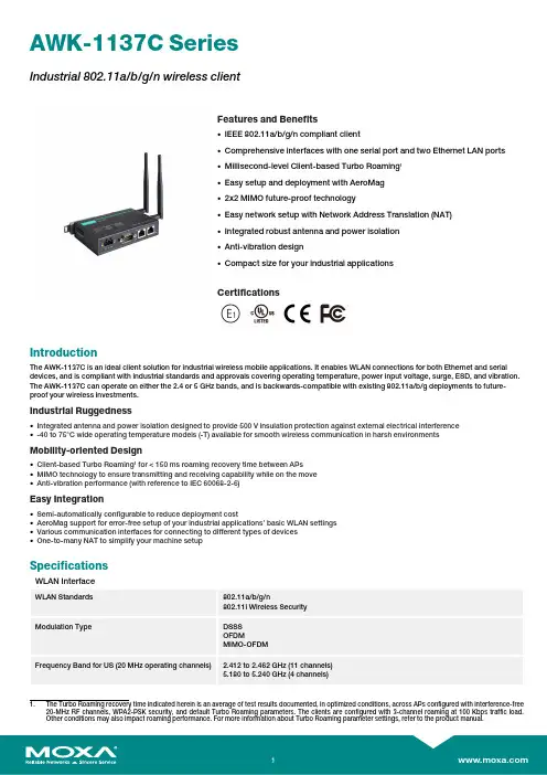
AWK-1137C SeriesIndustrial 802.11a/b/g/n wireless clientFeatures and Benefits•IEEE 802.11a/b/g/n compliant client•Comprehensive interfaces with one serial port and two Ethernet LAN ports •Millisecond-level Client-based Turbo Roaming 1•Easy setup and deployment with AeroMag •2x2MIMO future-proof technology•Easy network setup with Network Address Translation (NAT)•Integrated robust antenna and power isolation •Anti-vibration design•Compact size for your industrial applicationsCertificationsIntroductionThe AWK-1137C is an ideal client solution for industrial wireless mobile applications.It enables WLAN connections for both Ethernet and serial devices,and is compliant with industrial standards and approvals covering operating temperature,power input voltage,surge,ESD,and vibration.The AWK-1137C can operate on either the 2.4or 5GHz bands,and is backwards-compatible with existing 802.11a/b/g deployments to future-proof your wireless investments.Industrial Ruggedness•Integrated antenna and power isolation designed to provide 500V insulation protection against external electrical interference •-40to 75°C wide operating temperature models (-T)available for smooth wireless communication in harsh environmentsMobility-oriented Design•Client-based Turbo Roaming 1for <150ms roaming recovery time between APs •MIMO technology to ensure transmitting and receiving capability while on the move •Anti-vibration performance (with reference to IEC 60068-2-6)Easy Integration•Semi-automatically configurable to reduce deployment cost•AeroMag support for error-free setup of your industrial applications’basic WLAN settings •Various communication interfaces for connecting to different types of devices •One-to-many NAT to simplify your machine setupSpecificationsWLAN InterfaceWLAN Standards802.11a/b/g/n802.11i Wireless Security Modulation TypeDSSS OFDMMIMO-OFDMFrequency Band for US (20MHz operating channels)2.412to 2.462GHz (11channels)5.180to 5.240GHz (4channels)1.The Turbo Roaming recovery time indicated herein is an average of test results documented,in optimized conditions,across APs configured with interference-free 20-MHz RF channels,WPA2-PSK security,and default Turbo Roaming parameters.The clients are configured with 3-channel roaming at 100Kbps traffic load.Other conditions may also impact roaming performance.For more information about Turbo Roaming parameter settings,refer to the product manual.5.260to5.320GHz(4channels)25.500to5.700GHz(11channels)25.745to5.825GHz(5channels)Frequency Band for EU(20MHz operating channels) 2.412to2.472GHz(13channels)5.180to5.240GHz(4channels)5.260to5.320GHz(4channels)25.500to5.700GHz(11channels)2Frequency Band for JP(20MHz operating channels) 2.412to2.484GHz(14channels)5.180to5.240GHz(4channels)5.260to5.320GHz(4channels)25.500to5.700GHz(11channels)2Wireless Security WEP encryption(64-bit and128-bit)WPA/WPA2-Enterprise(IEEE802.1X/RADIUS,TKIP,AES)WPA/WPA2-PersonalTransmission Rate802.11b:1to11Mbps802.11a/g:6to54Mbps802.11n:6.5to300MbpsTransmitter Power for802.11a23±1.5dBm@6to24Mbps21±1.5dBm@36Mbps20±1.5dBm@48Mbps18±1.5dBm@54MbpsTransmitter Power for802.11n(5GHz)23±1.5dBm@MCS0/820MHz18±1.5dBm@MCS7/1520MHz23±1.5dBm@MCS0/840MHz18±1.5dBm@MCS7/1540MHzTransmitter Power for802.11b26±1.5dBm@1Mbps26±1.5dBm@2Mbps26±1.5dBm@5.5Mbps25±1.5dBm@11MbpsTransmitter Power for802.11g23±1.5dBm@6to24Mbps22±1.5dBm@36Mbps20±1.5dBm@48Mbps19±1.5dBm@54MbpsTransmitter Power for802.11n(2.4GHz)23±1.5dBm@MCS0/820MHz17±1.5dBm@MCS7/1520MHz23±1.5dBm@MCS0/840MHz17±1.5dBm@MCS7/1540MHzTransmitter Power2.4GHz26dBm18dBm18dBm5GHz(UNII-1)23dBm23dBm23dBm5GHz(UNII-2)23dBm23dBm23dBm5GHz(UNII-2e)23dBm23dBm23dBm5GHz(UNII-3)23dBm––Note:Based on regional regulations,the maximum transmission power allowed onthe UNII bands is restricted in the firmware,as indicated above.Receiver Sensitivity for802.11a(measured at5.680 GHz)Typ.-90@6Mbps Typ.-88@9Mbps Typ.-87@12Mbps Typ.-85@18Mbps Typ.-81@24Mbps Typ.-78@36Mbps2.DFS(Dynamic Frequency Selection)channel support:In AP mode,when a radar signal is detected,the device will automatically switch to another channel.However,according to regulations,after switching channels,a60-second availability check period is required before starting the service.Typ.-74@48Mbps Typ.-73@54Mbps Note3Receiver Sensitivity for802.11n(5GHz;measured at 5.680GHz)Typ.-69dBm@MCS720MHz Typ.-70dBm@MCS1520MHz Typ.-64dBm@MCS740MHz Typ.-66dBm@MCS1540MHz Note3Receiver Sensitivity for802.11b(measured at2.437 GHz)Typ.-89dBm@1Mbps Typ.-89dBm@2Mbps Typ.-89dBm@5.5Mbps Typ.-88dBm@11MbpsReceiver Sensitivity for802.11g(measured at2.437 GHz)Typ.-88dBm@6Mbps Typ.-88dBm@9Mbps Typ.-88dBm@12Mbps Typ.-87dBm@18Mbps Typ.-84dBm@24Mbps Typ.-81dBm@36Mbps Typ.-77dBm@48Mbps Typ.-75dBm@54MbpsReceiver Sensitivity for802.11n(2.4GHz;measured at2.437GHz)Typ.-70dBm@MCS720MHz Typ.-70dBm@MCS1520MHz Typ.-64dBm@MCS740MHz Typ.-65dBm@MCS1540MHzWLAN Operation Mode Client,Client-Router,Slave,SnifferAntenna External,2/2dBi,Omni-directionalAntenna Connectors2RP-SMA femaleEthernet Interface10/100BaseT(X)Ports(RJ45connector)2Standards IEEE802.3for10BaseTIEEE802.3u for100BaseT(X)IEEE802.1Q for VLAN TaggingEthernet Software FeaturesManagement DHCP Server/Client,HTTP,IPv4,LLDP,SMTP,SNMPv1/v2c/v3,Syslog,TCP/IP,Telnet,UDP,Proxy ARP,VLAN,Wireless Search Utility,MXview,MXconfigRouting Port forwarding,Static Route,NATSecurity HTTPS/SSL,RADIUS,SSHTime Management NTP Client,SNTP ClientFirewallFilter ICMP,MAC address,IP protocol,Port-basedSerial InterfaceConnector DB9maleSerial Standards RS-232,RS-422/485,RS-232/422/485Operation Modes Disabled,Real COM,RFC2217,TCP Client,TCP Server,UDPData Bits5,6,7,8Stop Bits1,1.5,23.Due to a limitation in the receiver sensitivity performance for channels153and161,it is recommended to avoid using these channels in your critical applications.Parity None,Even,Odd,Space,MarkFlow Control None,RTS/CTS,XON/XOFFBaudrate75bps to921.6kbpsSerial Data Log256KBSerial SignalsRS-232TxD,RxD,RTS,CTS,DCD,GND,DTR,DSRRS-422Tx+,Tx-,Rx+,Rx-,GNDRS-485-2w Data+,Data-,GNDRS-485-4w Tx+,Tx-,Rx+,Rx-,GNDLED InterfaceLED Indicators SYS,LAN1,LAN2,WLAN,SerialInput/Output InterfaceButtons Reset buttonPhysical CharacteristicsHousing MetalIP Rating IP30Dimensions77.1x115.5x26mm(3.04x4.55x1.02in)Weight470g(1.03lb)Installation DIN-rail mounting,Wall mounting(with optional kit) Power ParametersInput Voltage9to30VDCPower Connector1removable3-contact terminal block(s)Power Consumption11.7W(max.)Reverse Polarity Protection SupportedEnvironmental LimitsOperating Temperature Standard Models:0to60°C(32to140°F)Wide Temp.Models:-40to75°C(-40to167°F) Storage Temperature(package included)-40to85°C(-40to185°F)Ambient Relative Humidity5to95%(non-condensing)Standards and CertificationsEMC EN61000-6-2/-6-4,EN55032/24EMI CISPR22,FCC Part15B Class AEMS IEC61000-4-2ESD:Contact:8kV;Air:15kVIEC61000-4-3RS:80MHz to1GHz:10V/mIEC61000-4-4EFT:Power:2kV;Signal:1kVIEC61000-4-5Surge:Power:2kV;Signal:1kVIEC61000-4-6CS:10VIEC61000-4-8PFMFRadio EN300328,EN301489-1/17,EN301893,FCC ID SLE-1137C,ANATEL,MIC,NCC,SRRC,WPC,KC,RCMRoad Vehicles E mark E1Safety EN60950-1,UL60950-1Vibration IEC60068-2-6MTBFTime1,125,942hrsStandards Telcordia SR332WarrantyWarranty Period5yearsDetails See /warrantyPackage ContentsDevice1x AWK-1137C Series wireless clientInstallation Kit1x DIN-rail kitAntenna2x2.4/5GHz antennaDocumentation1x quick installation guide1x warranty cardDimensionsOrdering InformationAWK-1137C-EU EU802.11a/b/g/n0to60°C AWK-1137C-EU-T EU802.11a/b/g/n-40to75°C AWK-1137C-JP JP802.11a/b/g/n0to60°C AWK-1137C-JP-T JP802.11a/b/g/n-40to75°C AWK-1137C-US US802.11a/b/g/n0to60°C AWK-1137C-US-T US802.11a/b/g/n-40to75°C Accessories(sold separately)AntennasANT-WDB-ANF-0407 2.4/5GHz,omni-directional antenna,4/7dBi,N-type(male)ANT-WDB-ANF-0609 2.4/5GHz,omni-directional antenna,6/9dBi,N-type(female)ANT-WDB-ANM-0306 2.4/5GHz,omni-directional antenna,3/6dBi,N-type(male)ANT-WDB-ANM-0407 2.4/5GHz,dual-band omni-directional antenna,4/7dBi,N-type(male)ANT-WDB-ANM-0502 2.4/5GHz,omni-directional antenna,5/2dBi,N-type(male)ANT-WDB-ANM-0609 2.4/5GHz,omni-directional antenna,6/9dBi,N-type(male)ANT-WDB-ARM-02 2.4/5GHz,omni-directional rubber duck antenna,2dBi,RP-SMA(male)ANT-WDB-ARM-0202 2.4/5GHz,panel antenna,2/2dBi,RP-SMA(male)ANT-WDB-PNF-1518 2.4/5GHz,panel antenna,15/18dBi,N-type(female)MAT-WDB-CA-RM-2-0205 2.4/5GHz,ceiling antenna,2/5dBi,MIMO2x2,RP-SMA-type(male)MAT-WDB-DA-RM-2-0203-1m 2.4/5GHz,desktop antenna,2/3dBi,MIMO2x2,RP-SMA-type(male),1m cableMAT-WDB-PA-NF-2-0708 2.4/5GHz,panel antenna,7/8dBi,MIMO2x2,N-type(female)ANT-WSB5-ANF-125GHz,omni-directional antenna,12dBi,N-type(female)ANT-WSB5-PNF-185GHz,directional panel antenna,18dBi,N-type(female)ANT-WSB-ANF-09 2.4GHz,omni-directional antenna,9dBi,N-type(female)ANT-WSB-PNF-12 2.4GHz,directional panel antenna,12dBi,N-type(female)ANT-WSB-PNF-18 2.4GHz,directional panel antenna,18dBi,N-type(female)ANT-WSB-AHRM-05-1.5m 2.4GHz,omni-directional/dipole antenna,5dBi,RP-SMA(male),1.5m cableWireless Antenna CablesA-CRF-RFRM-S2-60SS402cable,RP-SMA(male)to RP-SMA(female)A-CRF-RFRM-R4-150RF magnetic stand,RP-SMA(male)to RP-SMA(female),RG-174/U cable,1.5mA-CRF-RMNM-L1-300N-type(male)to RP SMA(male),LMR-195Lite cable,3mA-CRF-RMNM-L1-600N-type(male)to RP SMA(male),LMR-195Lite cable,6mA-CRF-RMNM-L1-900N-type(male)to RP SMA(male),LMR-195Lite cable,9mCRF-N0117SA-3M N-type(male)to RP SMA(male),CFD200cable,3mSurge ArrestorsA-SA-NFNF-01Surge arrestor,N-type(female)to N-type(female)A-SA-NMNF-01Surge arrester,N-type(female)to N-type(male)Wireless AdaptersA-ADP-RJ458P-DB9F-ABC01DB9female to RJ45connector for the ABC-01Wireless Terminating ResistorsA-TRM-50-NM Terminating Resistor,50ohm,RP-SMA MaleWall-Mounting KitsWK-35-01Wall-mounting kit,2plates,6screws,35x44x2.5mm©Moxa Inc.All rights reserved.Updated Nov18,2019.This document and any portion thereof may not be reproduced or used in any manner whatsoever without the express written permission of Moxa Inc.Product specifications subject to change without notice.Visit our website for the most up-to-date product information.。

物联网边缘计算节点配置物联网边缘计算节点配置物联网边缘计算节点是物联网系统中的重要组成部分,它承担着处理数据、运行应用程序以及连接物联网设备的任务。
边缘计算节点的配置对于物联网系统的性能和稳定性至关重要。
接下来,我们将详细介绍物联网边缘计算节点的配置要点。
首先,边缘计算节点需要具备足够的计算能力。
物联网系统中的数据量庞大,因此边缘计算节点需要具备强大的处理能力,能够快速地处理和分析大量的数据。
通常,边缘计算节点需要搭载高性能的处理器和大容量的内存,以确保系统的高效运行。
其次,边缘计算节点需要具备稳定的网络连接能力。
物联网设备通常分布在不同的地理位置,因此边缘计算节点需要能够稳定地连接到各个设备,并能够实时地接收和发送数据。
为了确保网络的稳定性,边缘计算节点需要支持各种通信协议和网络技术,并具备高速的数据传输能力。
此外,边缘计算节点还需要具备良好的安全性能。
物联网系统中的数据通常包含敏感信息,因此边缘计算节点需要能够保护这些数据的安全。
边缘计算节点需要支持数据的加密和解密,以确保数据在传输和存储过程中的安全性。
此外,边缘计算节点还需要具备防火墙和入侵检测系统等安全防护措施,以防止恶意攻击和未经授权的访问。
最后,边缘计算节点还需要具备良好的可扩展性。
随着物联网系统的不断发展,设备数量和数据量可能会不断增加,因此边缘计算节点需要具备良好的扩展性,能够适应系统的发展需求。
边缘计算节点应该支持模块化的设计,以方便增加和替换硬件组件,同时还需要支持软件的升级和扩展,以提供更多的功能和服务。
综上所述,物联网边缘计算节点的配置对于系统的性能和稳定性起着重要的作用。
边缘计算节点需要具备足够的计算能力、稳定的网络连接能力、良好的安全性能以及良好的可扩展性。
只有在合理配置边缘计算节点的前提下,物联网系统才能够高效地运行,并为用户提供优质的服务。

基于变长基因算法的服务质量驱动多路径Web服务组合姜红红;杨小虎;徐远;柯杰瑞【摘要】Combined with Petri net, a variable length chromosome Genetic Algorithm (GA) was proposed to handle QoS-aware service composition among multiple composite structures (paths) problem. Petri net was used to express kinds of Web Service composite structures. It listed all the execution sequences of Web Service to fulfill the user's functional requirements. Subsequently, parallel service execution structures were found out and added into execution sequence so as to modify execution sequence to represent the unique path. Based on paths from Petri net, the variable length chromosome GA represented composited services in multiple paths by variable length chromosomes and conducted the gene crossover operation by service parameters matching to implement the optimum Quality of Service (QoS) composition service search in multi-path. Based on the proposed algorithm, two improvements were put forward to enhance the stability of the algorithm. One was used to choose better initial generation and the other was to optimize the stage generations. Scalability of the algorithm was analyzed theoretically and experimental results demonstrated its effectiveness by comparing to traditional GA.%为解决在不同服务组合结构(路径)上的服务质量驱动服务组合问题,提出了一种结合Petri网的变长基因算法.用Petri网描述子服务的各种组合结构,列举出所有路径上能实现功能需求的服务执行序列,进一步找出并添加执行序列中的服务并发执行结构,以修正执行序列使之与路径对应,唯一代表路径;而变长基因算法则用不同长度的染色体代表不同路径上的组合服务,并通过服务参数的匹配实现基因的交叉互换,以最终实现在不同路径上搜寻服务质量最优的组合服务.基于所提算法,提出增强初始群体、优化中间群体两点改进,以提高算法稳定性.理论证明该算法具有良好的扩展性,且与传统遗传算法的对比验证了算法的有效性.【期刊名称】《计算机集成制造系统》【年(卷),期】2011(017)006【总页数】10页(P1334-1343)【关键词】服务组合;Petri网;遗传算法;多路径;变长染色体;Web服务【作者】姜红红;杨小虎;徐远;柯杰瑞【作者单位】浙江大学计算机科学与技术学院,浙江杭州310027;浙江大学计算机科学与技术学院,浙江杭州310027;道富信息科技(浙江)有限公司,浙江杭州310030;道富信息科技(浙江)有限公司,浙江杭州310030【正文语种】中文【中图分类】TP3930 引言Web服务的核心技术和架构支持了服务的多元化,服务提供商可以独立提供实现部分功能的Web服务,应用时根据用户的需求再将这些服务组合起来,实现完整的商务功能。
The PowerSwitch S5200-ON 25/100GbE fixed switches comprise Dell EMC’s latest disaggregated hardware and software data center networking solutions, providing state-of-the-art, high-density 25/100GbE ports and abroad range of functionality to meet the growing demands of today’s data center environment. These innovative, next-generation open networking switches offer optimum flexibility and cost-effectiveness for web 2.0, enterprise, mid- market and cloud service provider with demanding compute and storage traffic environments.The S5200-ON is a complete family of switches: 12-port, 24-port, and 48-port 25GbE/100GbE ToR switches, 96-port 25GbE/100GbE Middle of Row (MoR)/End of Row (EoR) switch, and a 32-port 100GbE Multi-Rate Spine/Leaf switch. From the compact half-rack width S5212F-ON providing an ideal form factor for hyper-convergeddeployments, to the high density S5296F-ON for Middle of Row deployments, the S5200-ON series offersperformance and flexibility for a variety of network designs.In addition to 100GbE Spine/Leaf deployments, theS5232F-ON can also be used in high density deployments using breakout cables to achieve up to 128 10GbE or 128 25GbE ports.Using industry-leading hardware and a choice of Dell EMC’s OS10 or select 3rd party network operatingsystems and tools, the S5200-ON switches incorporate multiple architectural features that optimize data center network flexibility, efficiency and availability, including IO panel to PSU or PSU to IO panel airflow for hot/cold aisle environments, redundant, hot-swappable power supplies and fans and deliver non-blocking performance for workloads sensitive to packet loss.Priority-based flow control (PFC), data center bridge exchange (DCBX) and enhanced transmission selection(ETS) make the S5200-ON family ideally suited for DCB environments.Dell EMC PowerSwitch S5200-ON switches support the open source Open Network Install Environment (ONIE) for zero touch installation of Dell EMC’s OS10 networking operating system, as well as alternative network operating systems.Key applications• Organizations looking to enter the software-defined data center era with a choice of networking technologies designed to maximize flexibility • High-density 10/25GbE ToR server aggregation in high-performance data center environments at the desired fabric speed with the S5248F-ON or S5296F-ON• Low-density 10/25GbE server and storage aggregation with the S5212F-ON and S5224F-ON• Small-scale Fabric implementation via the S5232F-ON switch in leaf and spine along with S5248F-ON 1/10/25GbE ToR switches enabling cost-effective aggregation of 10/25/40/50/100 uplinks• Multi-functional 10/25/40/50/100GbE switching in High Performance Computing Clusters or other business-sensitive deployments requiring the highest bandwidth.• iSCSI deployments, including DCB converged lossless transactions• Single-pass VXLAN routing (future software release)Dell EMC PowerSwitch S5200-ON Series SwitchesHigh-performance, open networking 25GbE top-of-rack and 100GbEspine/leaf switchesKey features• 1 or 2RU high-density ToR switches with up to 48 or 96 ports of 25GbE or 32 ports of 100GbE• Multi-rate 100GbE ports support 10/25/40/50/100GbE • Scalable L2 and L3 Ethernet switching with QoS anda full complement of standards-based IPv4 and IPv6features, including OSPF and BGP routing support • Line-rate performance via non-blocking switchfabrics: 3.2Tbps (6.4Tbps full-duplex) on S5296F-ONand S5232F-ON, 2.0Tbps (4.0Tbps full-duplex) onS5248F-ON, and 1.08Tbps (2.16Tbps full-duplex) onS5224F-ON and S5212F-ON• L2 multipath support via Virtual Link Trunking (VLT)and Routed VLT support• VXLAN gateway functionality support for bridging and routing the non-virtualized and the virtualized overlaynetworks with line rate performance (hardware only)• Support for OS10 Enterprise Edition• Converged network support for DCB, with priority flow control (802.1Qbb), ETS (802.1Qaz), DCBx and iSCSI TLV support• Routable RoCE to enable convergence of computeand storage on Leaf/Spine Fabric• IO panel to PSU airflow or PSU to IO panel airflowRedundant, hot-swappable power supplies and fans on most models• Supports the open source Open Network InstallEnvironment (ONIE) for zero touch installation ofalternate network operating systems• L2 VXLAN (Static VXLAN with VLT, BGP EVPN)• Tool-less enterprise ReadyRails™ mounting kits formost models reducing time and resources for switchrack installation (S5212F-ON will utilize a tandem tray for mounting)• Power-efficient operation and Dell Fresh Air 2.0compliant up to 45ºC helps reduce cooling costs intemperature constrained deploymentsKey features with Dell EMC Networking OS10• Consistent DevOps framework across compute,storage and networking elements• Standard networking features, interfaces and scripting functions for legacy network operations integration • Standards-based switching hardware abstraction viaSwitch Abstraction Interface (SAI)• Pervasive, unrestricted developer environment viaControl Plane Services (CPS)• OS10 Enterprise Edition software enables Dell EMClayer 2 and 3 switching and routing protocols withintegrated IP services, quality of service, manageability and automation features• Leverage common open source tools and bestpractices (data models, commit rollbacks*)• Increase VM Mobility region by stretching L2 VLANwithin or across two DCs with unique VLT capabilities • Scalable L2 and L3 Ethernet Switching with QoS, ACL and a full complement of standards based IPv4 andIPv6 features including OSPF, BGP and PBR• Enhanced mirroring capabilities including localmirroring, Remote Port Mirroring (RPM), andEncapsulated Remote Port Mirroring (ERPM)• Converged network support for Data Center Bridging, with priority flow control (802.1Qbb), ETS (802.1Qaz), DCBx and iSCSI TLV*Roadmap1 RJ45 console/management port with RS232 signalingS5212F-ON: 12x25GbE SFP28 + 3x 100GbE QSFP28S5224F-ON: 24x25GbE SFP28 + 4x 100GbE QSFP28S5248F-ON: 48x25GbE SFP28 + 4x 100GbE QSFP28 + 2x 2x100GbE QSFP28-DDS5296F-ON: 96x25GbE SFP28 + 8x 100GbE QSFP28S5232F-ON: 32x100GbE QSFP28 ports +2xSFP+ 10GbEEnvironmentalPower supply: 100–240 VAC 50/60 HzMax Operating specifications:AC Max. Operating specifications: Operating temperature: 32° to 113°F(0° to 45°C)Operating humidity: 5 to 90% (RH),non-condensingMax. Non-operating specifications:Storage temperature: –40° to 158°F(–40° to 70°C)Storage humidity: 5 to 90% (RH), non- condensingFresh air Compliant to 45°CRedundancyHot swappable redundant powerHot swappable redundant fans (fixed power supply and fans on S5212F-ON)PerformancePacket buffer memory: 32MBCPU memory: 16GBMAC addresses: 160KARP table: 128KIPv4 routes: 128KIPv6 routes: 64KMulticast hosts: 32KLink aggregation: 16 links per group, 128 groups Layer 2 VLANs: 4KMSTP: 64 instancesLAG load balancing: Based on layer 2, IPv4 or IPv6 headersIEEE Compliance802.1AB LLDPTIA-1057 LLDP-MED802.3ad Link Aggregation802.1D Bridging, STP802.1p L2 Prioritization802.1Q VLAN Tagging802.1Qbb PFC 802.1X Network Access Control802.3ac Frame Extensions for VLANTagging802.3x Flow ControlLayer2 Protocols802.1D Compatible802.1p L2 Prioritization802.1Q VLAN Tagging802.1s MSTP802.1w RSTP802.1t RPVST+VLT (Virtual Link Trunking)VRRP Active/ActiveRSTP & RPVST+Port Mirroring on VLT portsDCB, iSCSI, FSB on VLTRPM/ERPM over VLTVLT Minloss upgradeRFC Compliance768 UDP793 TCP854 Telnet959 FTP1321 MD51350 TFTP2474 Differentiated Services2698 Two Rate Three Color Marker3164 Syslog4254 SSHv2General IPv4 Protocols791 IPv4792 ICMP826 ARP1027 Proxy ARP1035 DNS (client)1042 Ethernet Transmission1191 Path MTU Discovery1305 NTPv41519 CIDR1812 Routers, Static Routes1858 IP Fragment Filtering2131 DHCPv4 (server and relay)5798 VRRPv33021 31-bit Prefixes1812 Requirements for IPv4 Routers1918 Address Allocation for PrivateInternets2474 Diffserv Field in IPv4 and Ipv6Headers2597 Assured Forwarding PHB Group3195 Reliable Delivery for Syslog3246 Expedited Forwarding PHB GroupVRF (BGPv4/v6)1981 Path MTU for IPv62372 IPv6 Addressing2460 IPv6 Protocol Specification2461 Neighbor Discovery2462 Stateless Address AutoConfig2711 IPv6 Router alert2463 ICMPv62464 Ethernet Transmission2675 IPv6 Jumbograms3484 Default Address Selection3493 Basic Socket Interface4291 Addressing Architecture3542 Advanced Sockets API3587 Global Unicast Address Format4291 IPv6 Addressing2464 Transmission of IPv6 Packets overEthernet Networks2711 IPv6 Router Alert Option4007 IPv6 Scoped Address Architecture4213 Transition Mechanisms for IPv6 Hostsand Routers3315 DHCPv6 Server & RelayIPv6 Static RoutesOSPF1745 OSPF/BGP interaction1765 OSPF Database overflow2154 OSPF with DigitalSignatures2328 OSPFv25340 OSPF for IPv6 (OSPFv3)2370 Opaque LSA3101 OSPF NSSA4552 OSPFv3 AuthenticationMulticast4541 IGMPv1/v2/v3 and MLDv1/v2SnoopingSecurity2865 RADIUS3162 Radius and IPv63579 Radius support for EAP3580 802.1X with RADIUS3826 AES Cipher in SNMP1492 TACACS (Authentication, Accounting)Control Plane, VTY & SNMP ACLsIP Access Control ListsBGP1997 Communities2385 MD52439 Route Flap Damping2796 Route Reflection2918 Route Refresh3065 Confederations4271 BGP-42545 BGP-4 Multiprotocol Extensions for IPv6 Inter-Domain Routing2858 Multiprotocol Extensions4360 Extended Communities4893 4-byte ASN5396 4-byte ASN Representation5492 Capabilities Advertisementdraft-ietf-idr-add-paths-04.txt ADD PATHLinux DistributionDebian Linux version 9Linux Kernel 4.9Network Management and Monitoring SNMPv1/2cIPv4/IPv6 Management support (Telnet, FTP, TACACS, RADIUS, SSH, NTP)SyslogPort MirroringRPM/ERPM3176 SFlowSupport Assist (Phone Home)RestConf APIs (Layer 2 features)XML SchemaCLI Commit (Scratchpad)Uplink Failure DetectionObject TrackingBidirectional Forwarding Detection (BFD) AutomationControl Plane Services APIsLinux Utilities and Scripting ToolsCLI Automation (Multiline Alias)Zero Touch Deployment (ZTD)Ansible, Puppet, Chef, SaltStack8040 RESTCONF APIs (L3)Quality of ServicePrefix ListRoute-MapRate Shaping (Egress)Rate Policing (Ingress)Scheduling AlgorithmsRound RobinWeighted Round RobinDeficit Round RobinStrict PriorityWeighted Random Early DetectData center bridging802.1Qbb Priority-Based Flow Control802.1Qaz Enhanced TransmissionSelection (ETS)Explicit Congestion NotificationData Center Bridging eXchange (DCBx)DCBx Application TLV (iSCSI, FCoE)RoCEv2Software Defined NetworkingOpenFlow 1.3 (Native)MIBSIP MIBIP Forward MIBHost Resources MIBIF MIBLLDP EXT1/3 MIBEntity MIBLAG MIBDell-Vendor MIBTCP MIBUDP MIBSNMPv2 MIBETHERLIKE-MIBSFLOW-MIBPFC-MIBRegulatory complianceSafetyUL/CSA 60950-1, Second EditionEN 60950-1, Second EditionIEC 60950-1, Second Edition Including AllNational Deviations and Group DifferencesEN 60825-1 Safety of Laser Products Part 1:Equipment Classification Requirements andUser’s GuideEN 60825-2 Safety of Laser Products Part 2:Safety of Optical Fibre CommunicationSystemsFDA Regulation 21 CFR 1040.10 and 1040.11EmissionsAustralia/New Zealand: AS/NZS CISPR 22:2006, Class ACanada: ICES-003, Issue-4, Class AEurope: EN 55022: 2006+A1:2007(CISPR 22: 2006), Class AJapan: VCCI V3/2009 Class AUSA: FCC CFR 47 Part 15, Subpart B:2011,Class AImmunityEN 300 386 V1.4.1:2008 EMC for NetworkEquipmentEN 55024: 1998 + A1: 2001 + A2: 2003EN 61000-3-2: Harmonic CurrentEmissionsEN 61000-3-3: Voltage Fluctuations andFlickerEN 61000-4-2: ESDEN 61000-4-3: Radiated ImmunityEN 61000-4-4: EFTEN 61000-4-5: SurgeEN 61000-4-6: Low Frequency ConductedImmunityRoHSAll S Series components are EU RoHScompliant.CertificationsAvailable with US Trade Agreements Act(TAA) complianceUSGv6 Host and Router Certified on DellNetworking OS 9.5 and greaterIPv6 Ready for both Host and RouterUCR DoD APL (core and distributionALSAN switchWarranty1 year return to depot© 2018 Dell Inc. or its subsidiaries. All Rights Reserved. Dell, EMC and other trademarks are trademarks of Dell Inc. or its subsidiaries. Other trademarks may be trademarks of their respective owners.Learn more at /NetworkingLearn more at /ServicesIT Lifecycle Services for NetworkingExperts, insights and easeOur highly trained experts, with innovative tools and proven processes, help you transform your IT investments into strategic advantages.Plan & DesignLet us analyze your multivendor environment and deliver a comprehensive report and action plan to build upon the existing network and improve performance.Deploy & IntegrateGet new wired or wireless network technology installed and configured with ProDeploy. Reduce costs, save time, and get up and running fast.EducateEnsure your staff builds the right skills for long-term success. Get certified on Dell EMC Networking technology and learn how to increase performance and optimize infrastructure.Manage & SupportGain access to technical experts and quickly resolve multivendor networking challenges with ProSupport. Spend less time resolving network issues and more time innovating.OptimizeMaximize performance for dynamic ITenvironments with Dell EMC Optimize. Benefit from in-depth predictive analysis, remotemonitoring and a dedicated systems analyst for your network.RetireWe can help you resell or retire excess hardware while meeting local regulatory guidelines and acting in an environmentallyresponsible way.。
2010年8月第16卷第3期安庆师范学院学报(自然科学版)J o ur nal o f A nqi ng T eac her s C ol lege(N at u r al Sci ence Edi t ion)A ug.2010V01.16N o.3一种支持Q O S约束面向语义的w eb服务发现机制刘奎,赵晓静(安庆师范学院计算机与信息学院,安徽安庆246133)擅耍:传统的服务发现技术是建立在语法描述的基础上,主要采用的服务发现机制是W SD L和U D D I规范相结合的解决方案,这些发现方法查准率极其低下,不能很好的满足用户需要。
为此.提出了一种支持Q O S约束的面向语义的w eb服务发现机制,给出了w e b服务发现框架与服务发现算法,从而提高查准率。
关t词:本体,w eb服务发现;语义w eb;服务匹配;Q O S中图分类号:T Pl82文献标识码:A文章编号:1007--4260(2010)03--0049--040引言近些年,在语义w eb服务中,基于功能的服务匹配规则一般是计算服务请求模型和服务描述中的输入、输出的语义相似性。
基于非功能的服务匹配规则多数是基于w eb服务的Q O S属性计算的,可以很好地满足用户要求。
虽然目前出现将功能属性与非功能属性同时作为不可缺的因素来考虑,但是随着w e b中服务数量的剧增,如果首先不考虑分类匹配进行预筛选,则较难快速、准确和高效地从这些大量w eb服务中动态地寻找最能满足用户需求的服务。
针对以上问题,提出了一种支持Q os约束的面向语义的w eb服务发现机制。
1服务描述模型目前,多数基于语义的服务发现方法都采用本体作为语义基础。
通过计算领域本体内的概念和概念之间的语义关系和相似程度,从而给出服务的匹配程度。
本体是一个源于哲学的概念,原指关于存在及其本质和规律的学说。
近些年作为信息抽象和知识的描述的工具被计算机领域所采用。
1998年St ude r等人提出了一个被广泛接受的定义,即“本体是共享概念模型的明确的形式化的规范说明。
240 •电子技术与软件工程 Electronic Technology & Software Engineering程序设计• Program Design【关键词】信息系统 32位激光码32位激光码,是采用激光打标的方式烧灼在条烟包装上的一种信息码段。
在非法流通卷烟案件的调查过程中,需要采集卷烟的品种、数量、来源地等信息,其中来源地的信息就设置在真品卷烟条包上的“32位激光码”内,通过32位码的前5位,可以准确判定该批卷烟在商业环节的分拣时间,6-14位是卷烟在工业环节出厂、商业环节入库派生的件烟序列号,15-16位主要是条烟在对应件烟中所处的位置(或排序号),17-20位是商业配送中心卷烟的自定义信息,21-32位是卷烟零售户的行政许可证号,可类似身份证信息。
因此32位码中每个部分的字符都有一定的追溯意义,条码信息越完整,对开展真烟追溯就越有价值。
对各码段信息的及时、准确抄录、上报、追溯是烟草专卖管理工作中真品卷烟案件不可或缺的关键步骤。
1 系统需求系统必须包括所采集数据解码、信息录入,具备以卷宗作为管理节点的案件管理模块,具备数据查询、统计分析、报表生成等基本功能。
是一个B/S 架构的管理系统。
整个系统从使用用户上覆盖省、市、县三级专卖管理部门及基层工作人员。
部分重点功能需求具体详细功能需求列举如下:(1)稽查大队案件码段信息录入。
功能描述:对32位激光码识读仪采集的信息进行解码并导入系统。
(2)案件登记。
功能描述:对录入案件进行信息填报。
32位激光码信息采集上位机程序设计文/郭军 王晋冰 陈玮 喻培源(3)品牌信息统计。
(4)条烟码明细。
功能描述:列出案件中条烟的32位激光码及对应来源地信息。
(5)案件信息导出。
(6)按查获地查询。
功能描述:按照卷烟查获地进行数据查询,可根据填报时间、立案时间、查获时间、立案单位信息进行筛选查询并导出报表。
(7)违法违规大户查询。
功能描述:统计来源地为同一零售户且案值超过5万元或5万支的案件,可根据填报时间、立案时间、查获时间进行筛选查询,并导出报表。
Multi-Class Latency-Bounded Web ServicesVikram Kanodia and Edward W.KnightlyDepartment of Electrical and Computer EngineeringRice UniversityIn Proceedings of IEEE/IFIP IWQoS2000Abstract—Two recent advances have resulted in significant improve-ments in web server quality-of-service.First,both centralized and dis-tributed web servers can provide isolation among service classes by fairly distributing system resources.Second,session admission control can protect classes from performance degradation due to overload.The goal of this work is to design a general“front-end”algorithm that uses these two building blocks to support a new web service model,namely,multi-class services which control response latencies to within pre-specified targets.Our key technique is to devise a general service abstraction to adaptively control not only the latency of a particular class,but also to assess the inter-class relationships.In this way,we capture the extent to which classes are isolated or share system resources(as determined by the server architecture and system internals)and hence their effects on each other’s QoS.For example,if the server provides class isolation(i.e., a minimum fraction of system resources independent of other classes), yet also allows a class to utilize unused resources from other classes, the algorithm infers and exploits this behavior,without an explicit low level model of the server.Thus,as new functionalities are incorporated into web servers,the approach naturally exploits their properties to effi-ciently satisfy the classes’performance targets.We validate the scheme with trace driven simulations.I.I NTRODUCTIONAn increasingly dominant factor in poor end-to-end perfor-mance of web traffic is excessive latencies due to overloaded web servers.Consequently,reducing and controlling server latencies is a key challenge for delivering end-to-end quality-of-service.Towards this end,two key mechanisms have been intro-duced to improve web QoS.First,admission control has been proposed as a mechanism to prevent web servers from en-tering overload situations[1],[2],[3].Specifically,by ad-mitting new sessions only if the measured load is below a pre-specified threshold,admission control can prevent the server from entering a regime in which latencies are exces-sive,or session throughput collapses due to dropped requests and aborted sessions.Second,web servers can now provide performance isola-tion and differentiation among the different service classes hosted by the site.In particular,a server may support a num-ber of service classes which may represent different classes of users or different applications(news,email,static docu-ments,dynamic content,etc.).Whether such classes are sup-ported in a single-node server or a distributed cluster,mecha-nisms devised in[4],[5],[6]and[7]respectively can ensure that each service class receives a certain share of system re-This research is supported in part by Nokia Corporation.Additional funding is provided by NSF CAREER Award ANI-9733610,NSF Grant ANI-9730104,and Texas Instruments.The authors may be reached via /networks.sources(disk,CPU,memory,etc.).Moreover,by appropri-ately weighting the share of system resources,differentiation among service classes is achieved.Similarly,as delays are also incurred in the system’s request queues,prioritization of incoming requests can further differentiate the performance among classes[1],[8].Thus,differentiation and isolation can be achieved by pri-oritized scheduling of system resources,and protection from overload can be achieved by admission control.However, even if taken together,these two mechanisms cannot en-sure that a request’s targeted delay will be satisfied.Con-sequently,because end-to-end latency is a key component of user-perceived quality-of-service,new mechanisms are needed to ensure that the service class’request delays are lim-ited to within the targeted value.In this paper,we introduce a new framework for multi-class web server control which can satisfy per-class latency constraints,and devise an algorithm termed Latency-targeted Multiclass Admission Control(LMAC).Our key technique is to design a scheme within a general framework of request and service envelopes.Such envelopes statistically describe the server’s request load and service capacity as a function of interval length,resulting in a high-level service abstraction which circumvents the need to model or measure the com-ponents of a request’s delay.For example,a request incurs delays in the request queue,CPU processing,memory,disk in the case of cache misses,and so on:individually control-ling the latency in each subsystem is simply an intractable and impractical task in a modern server.Instead,we utilize the envelopes as a simple tool for controlling class quality-of-service while maximizing utilization of system resources. Our approach has three key distinctions.First,it enables web servers to support a strong service model with class laten-cies bounded to a pre-specified target,i.e.,a minimum frac-tion of accepted requests will be serviced within the class de-lay target.Second,it provides a mechanism to characterize and con-trol the inter-class relationships.For example,suppose server resources are allocated to classes in a weighted-fair manner so that classes have performance isolation,yet a class is able to utilize unused resources of other classes.In general,the extent to which an increased load in one class affects the per-formance of another class is a complex function of the to-tal system load,the particular resource scheduling algorithm, and the low-level interactions among the server’s resources. Building on the results of[9],we use the envelopes as a wayFRONT ENDBACKEND NODESFig.1.System Modelto characterize the high-level isolation/sharing relationships among classes and design a general multi-class algorithm to exploit these effects.Finally,by decoupling access control and resource alloca-tion from the internals of the server,we obtain a general solu-tion that applies to a broad class of servers,including single-node and distributed servers,and servers with varying levels of quality-of-service support.Consequently,as the server is enhanced with functionalities such as weighted-fair resource allocation,the algorithm naturally exploits these features to better utilize the available resources and support an increased number of sessions per service class.To evaluate our scheme,we perform a broad set of trace-driven-simulation experiments.We first compare our scheme with an uncontrolled system and illustrate that the algorithm is able to prevent performance degradation due to overload.Next,comparing the delays obtained in simulations with the class QoS objectives,we find that in many cases,latencies can be controlled to within several percent of the targeted value.Moreover,in the single-class case,we compare with a sim-ple queuing theoretic approach,and find that envelopes con-trol the system to a significantly higher degree of accuracy.Finally,in the multi-class case,simulations indicate that sub-stantial inter-class resource sharing gains are available.Here,we find that the approach is able to extract these gains,and ef-ficiently utilize system resources while satisfying each class’delay targets.The remainder of this paper is organized as follows.In Section II,we describe the server architecture and the system abstraction used for QoS management.Next,in Section III,we describe a simple single-class queuing theoretic approach to serve as a benchmark for performance analysis,and illus-tration of the key problems in meeting delay targets.In Sec-tion IV,we introduce the request and service envelopes and develop an access control algorithm based on the properties of these envelopes.We next describe the simulation scenarioand present experimental results in Sections V and VI respec-tively.Finally,in Section VII,we conclude.II.S YSTEM A RCHITECTUREIn this section we describe the basic system architecture of a scalable QoS web server.We are not proposing a new architecture as all of the mechanisms described below have been introduced previously.Rather,our goal is to consider a general system model for admission control which can exploit various QoS server mechanisms to efficiently satisfy targeted class latency objectives.Figure 1depicts the general system model that we con-sider.The system consists of a state-of-the-art web server augmented with admission control capabilities as in [1],[2],[3].All incoming requests,which can be sessions (as in [2])or individual “page”requests,are classified into differ-ent quality-of-service classes.There are a number of possible classification criteria including the address of the server (in case of web hosting applications),the identity of the user is-suing the request,or the particular application or data type.The goal of our admission control algorithm is to determine whether admission of a new request in a particular service class can be supported while meeting the latency targets of all classes.If it is not possible,the request should be rejected outright,or redirected to a lower priority class or a different server.As shown in the figure,incoming requests are first queued onto the listen queue or dropped if the listen queue is full.The admission controller dequeues requests from the listen queue and determines if they will admitted or rejected.Notice that the admission control unit is part of the front-end and mon-itors all of the server’s arrivals and departures.As depicted in Figure 2,the admission control unit performs observation-based control of the server using measured request and ser-vice rates of each class.Further,notice from Figure 2(b)that our class-based admission control will incorporate effects ofjja , a ,.... as , s ,...... sFig.2.Admission Control Modelinter-class resource sharing by also considering the effects of a new admission on other service classes.If admitted,requests are then scheduled according to the server’s request scheduling algorithm which can be first-come-first-serve or class based [1],[8].Finally,requests are submitted to the back-end nodes in a distributed server [7],or in the case of a single node server are simply processed by the node itself.A key point is that the admission controller applies to a general system model including single-node and distributed servers,FCFS and class-based scheduling,and standard as well as QoS-enhanced operating systems.When QoS mech-anisms are present in the server (such as class-based rather than FCFS request scheduling),the admission controller will measure the corresponding performance improvements and exploit the QoS functionality by admitting more requests per class,thereby increasing the overall system efficiency.For example,consider a server farm where the front-end does so-phisticated load balancing to achieve better overall through-put by exploiting locality information at the back-end [10].In this case,the admission controller will measure the decreased service latencies and be able to admit an increased number of sessions into various classes,thereby exploiting the effi-ciency gain of load balancing.Finally,notice from Figure 2that the admission controller does not measure or model re-sources at the operating system level,such as disk,memory,or CPU.Instead,we abstract all low-level resources into a vir-tual server which allows us to design an admission controller that is applicable to a broad class of web server architectures and applications.III.B ASELINE S CHEMEIn this section,we sketch a simple queuing theoretic algo-rithm devised to satisfy a delay target.The goal here is three-fold.First,we illustrate an abstraction of the server resources into a simple queuing model.Second,we highlight key is-sues for managing multi-class web services.Finally,we use the approach as a baseline for experimental comparisons and,by highlighting its limitations,we further motivate the LMAC scheme.A.Problem FormulationConsider a single class with quality-of-service targets given by a delay bound of 0.5seconds to be met by 99%of requests.Further consider a stationary and homogeneous arrival of ses-sions and requests within sessions,so that there exists some maximum number of requests per second which can be ser-viced so that this QoS requirement is met.If the overall arrival rate of requests to the server is greater than this maximum,the difference should be blocked (or redirected)by the access controller to prevent an overload situation.The key question is,how to determine which load level is the maximum one that can support the service.Specifi-cally,if the current load is below this maximum,then the cur-rent 99percentile delay will be below the target.However,when a new session requests access to the server,the new 99percentile delay of this class and others is in general a com-plex function of the system workload,and the low-level in-teractions among the many resources consumed such as disk,bandwidth,memory,and CPU.Below,we sketch a baseline approach for assessing the impact of new requests and ses-sions on the delay target via a simple queuing theoretic ab-straction.B.Sketch AlgorithmHere,we approximate class ’s service by an M/M/1queue with an unknown service rate.In particular,as described above,a request’s service latency includes delays from ses-sion queues,disk access,etc.The M/M/1model abstracts these resources into a single virtual server with independent and exponential requests and services as follows.Over the last seconds from the current time ,the meanservice time of request in classmean arrival rate of admitted class requests class target delayvariance of class requests over durations variance of class latency for concurrent requests(1) where is an indicator function,and the mean delay is(3) so that the delay violation probability under an increased load will be(4) Thus,the increased load due to the new session should be admitted if the estimated is less than the class’target.Consequently,under the particular assumptions of the M/M/1model,the above scheme limits the class’latency to within the target for the specified fraction of requests.C.Limitations of the Baseline SchemeWhile server access control based on Equations(1)-(4) does provide the ability to meet a class’latency objectives with a high level abstraction of system resources,it encoun-ters several key problems which preclude its practicality to realistic web servers.First,it offers no support for multiple services classes.That is,by treating each class independently,the impact of a new session on other classes is ignored.Second,the assumption that inter-request times are independent and exponentially distributed conflicts with measurement studies[11].Third, the assumption of independent and exponentially distributed service times cannot account for the highly variable service times of requests and ignores the strong effects of caching, namely,that consecutive requests for the same document can result in highly correlated,as well as highly variable,service times.In Section VI,we experimentally quantify the impact of these limitations in a realistic scenario.IV.M ULTI-C LASS A DMISSION C ONTROLIn this section,we build on the previous admission control model and introduce the Latency-targeted Multi-class Admis-sion Control(LMAC)algorithm.The goal is to provide a strong service model for web classes that controls statistical latency targets of multiple service classes.The LMAC al-gorithm has two key distinctions from the baseline scheme. First,we introduce use of envelopes as a general yet accu-rate way of describing a class’service and demand.As for the baseline scheme,this is a high-level workload and service characterization,yet,unlike the baseline scheme,envelopes capture effects of temporal correlation and high variability in requests and service latencies.Second,exploiting the inter-class theory of[9],we show how the performance effects of one class on another can be incorporated into admission con-trol decisions.A.Envelopes:A General Service and Demand Abstraction Deterministic[12]and statistical[9],[13]traffic envelopes have been developed to manage network QoS.Moreover,de-terministic[12]and statistical[9]service envelopes have pro-vided a foundation for multi-class network QoS,in[9],also incorporating inter-class resource sharing.Below,we extend these techniques to the scenario of measurement-based web services exploiting two key properties of envelopes:charac-terization of temporal correlation and variance and simple on-line measurement via jumping windows.Denoting the number of class requests in the interval0.10.20.30.40.5010203040506070Interval Length (sec)N u m b e r o f R e q u e s t s(a)Cumulative EnvelopeFig.3.95Percentile Request Envelopesby(5)the mean number of requests in an interval of length is,and the variance is given by(8)and likewise for the service variance .Notice thatas in Equation (2).Figure 4depicts an example service envelope from the sim-ulation experiments of Section VI.Analogous to Figure 3,it depicts the number of concurrent requests serviced as a func-tion of the the latency incurred.The key property of the figure is its convexity so that,for example,the time required to ser-vice requests is far less than times the time required to ser-vice 1request.This is due to the effects of caching (requestsNote that if the ’th request enters the system after the request is serviced,then this duration reflects the two request’s inter-arrival times rather than the time to service two requests.0.511.52020406080100Interval length (sec)N u m b e r o f R e q u e s t sFig.4.Service Envelopefor the same document within close temporal proximity expe-rience significantly smaller latencies)and more generally,the server’s ability to efficiently service concurrent requests.C.Sketch LMAC AlgorithmThe LMAC test is invoked upon arrival of a new session or request in class which will increase the request rate from itscurrent value to.The LMAC test consists of two parts:the first ensures class ’s delay target is satisfied and the second ensures that other classes will not suffer QoS vio-lations due to the increased workload of class .We illustrate the test pictorially using Figures 3and 4.For class itself,with a statistical characterization of both requests and service,maintaining a maximum horizontal dis-tance of between the two curves ensures that the delay tar-get is satisfied with probability (see [9],[14]for further details).With an increase in ,class itself increases its re-quest rate yet retains its previous service level.Hence,the latency target is satisfied if the two curves remain apartafter an increase ofin the request envelope.For classes,we must also consider the performance effects of class on class ’s delay targets.Our approach is to bound the effects of the incremental load.Specifically,by an upper bound on class ’s new latency,we ensure that class does not force class into QoS violations.Moreover,by applying this bound only to the incremental load the perfor-mance penalty for this worst case approach is mitigated.In other words,class ’s current service measurements incorpo-rate the effects of class ’s load ,so that onlyis included in the bound.The bound is obtained by consider-ing that the incremental requests have strict priority over class sessions.Under this worst-case scenario,class ’s workload remains the same yet its service over intervals oflength is decreased by.Hence,the new request can be admitted if each class can satisfy its ,even under a reduction in service by .We make three observations about the LMAC test.First,each class’service envelope captures the gains from inter-class resource sharing.For example,if class can exploit unused capacity from an idle or lower priority class ,class measures a correspondingly larger service envelope.Simi-larly,if the server has complete isolation of classes (e.g.,via separate back-end nodes in the extreme case),then no such gains will be available and the algorithm will correctly limit admissions to reflect this.Second,the algorithm also ensures class performance isolation,i.e.,that admissions in one class do not cause violations in another class,by incorporating the effects of inter-class interference.Finally,we note that while LMAC attempts to maximize the utilization of the web server subject to the QoS constraints independent of the server archi-tecture,QoS functionality in the server itself remains critical.For example,if a web server provides no QoS support and no class differentiation,LMAC infers that only a single service can truly be provided,and restricts admissions to satisfy the most stringent class requirements.Alternatively,when QoS mechanisms are deployed in the web server [4],[7],the re-sulting efficiency gains are in turn exploited by the LMAC algorithm,which increases the number of admitted sessions in each class and hence the overall system utilization.V.S IMULATION S CENARIOOur simulation scenario consists of a prototype imple-mentation of the LMAC algorithm built into the simula-tor described in [10],which was developed to approximate the behavior of OS management for CPU,memory and caching/disk storage.The front end node has a listen queue in which all incoming requests are queued before being ser-viced.Each back-end node consists of a CPU and locally attached disk(s)with separate queues for each.In addition,each node maintains its own main memory cache of config-urable size and replacement policy.Upon arrival,each request is queued onto the listen queue or dropped if the listen queue is full.Processing a request re-quires the following steps:dequeuing from the listen queue,connection establishment,disk reads (if needed),data trans-mission and finally connection tear down.The processing oc-curs as a sequence of CPU and I/O bursts.The CPU and I/O bursts of different requests can be overlapped but the individ-ual processing steps for each request must be performed in sequence.Also,data transmission immediately follows disk read for each block.We have used the same costs for basic request processing as in [10].The numbers were derived by performing measure-ments on a 300MHz Pentium II machine running FreeBSD 2.2.5and an aggressive experimental server.Connection establishment and tear down costs are set to 145s of CPU time each.Transmit processing costs are 40s of CPU time per 512bytes.Reading a file from the disk re-quires a latency of 28ms for 2seeks +rotational latency fol-lowed by a transfer time of 410s per 4KByte (resulting in a peak transfer rate of 10MBytes/sec).A file larger than 44KBytes is charged an additional latency of14ms(1seek+ rotational latency)for every44KByte block length in excess of44KBytes.The cache replacement policy is Greedy-Dual-Size[15].To incorporate cache behavior,we deliberately set the cache size in our simulation to be32MB.The small cache size effectively compensates for the relatively small data set of our traces.The input to the simulator are streams of tokenized re-quests,one stream for each user class.Requests within a user class arrive with a user defined mean rate.Each request rep-resents afile(and the correspondingfile size in bytes).We generate the arrival stream from logs collected from real web servers.One of the traces used in our simulations is generated from the CS departmental server log at Rice University.Although we do have the request arrival times embedded in the logs, they do not represent the workload of an overloaded web server.For simplicity we simulate inter-arrival times as expo-nential.(As this particular assumption is unrealistic,we plan to collect additional traces which also include access times.) The latency experienced by a request is the delay from the time the request arrives at the listen queue until the time when that connection is torn down.The time taken to make ad-mission control decisions are assumed to be negligible.This does not imply that we completely ignore the effect of the server time spent in processing eventually rejected requests. In fact as can be seen from Figure1,all admission control decisions are made after the server dequeues a request from the listen queue.Thus any rejected requests has used up some of the resources of the server(namely the time spent in thefi-nite sized listen queue).We ignore the actual processing time spent while making the admission control decision.VI.E XPERIMENTAL I NVESTIGATIONSIn this section,we describe the experiments performed to investigate the performance of the LMAC algorithm.Thefirst experiment was performed to demonstrate LMAC’s capabil-ity to actually protect the server from overload.In particular, without admission control,as the load offered to a server is in-creased beyond the server’s capacity,the request latencies be-come excessive.Admission control provides protection from overload by monitoring the utilization of the server and block-ing requests which will yield unacceptable performance. A.Overload ProtectionTo demonstrate the overload protection capabilities of the LMAC algorithm,we simulate various offered loads to the web server,keeping the targeted request latencies to be the same.We compare the performance of LMAC with a web server without admission control capabilities and measure the 95percentile delay in both cases.Figure5shows the results for a targeted delay of1second.As depicted in thefigure, latencies in the unmodified server increase without bound as the load is increased.On the other hand,the LMAC algorithmFig.5.95Percentile Latency vs.Loadblocks requests to meet the delay constraint and thus protects the web server from overload.In addition to overload pro-tection,thefigure indicates that LMAC controls latencies to within a small error of the target.B.AccuracyFor the second experiment,we compare the performance of LMAC with the queuing theoretic baseline approach of Sec-tion III.(We do not compare with admission control schemes from the literature as none have latency targets.)Figure6 shows the measured utilization versus95percentile delay for an offered load of200requests/sec.The server is a stand alone server with all incoming requests belonging to a sin-gle user class.The Baseline and the LMAC curves depict the throughput obtained when targeting95percentile delay values of.25,.5,1,1.25,1.5,1.75,2and2.5seconds.The Simulation curve depicts the measured value of95percentile delay and measured value of throughput when targeting theFig.6.Throughput vs.95Percentile LatencyClass Multi-class with Sharing Throughput(reqs/sec)Throughput(reqs/sec)1.467.50192145our approach can be applied to off-the-shelf servers enhanced with monitoring and admission control.Moreover,as QoS and performance functionalities are added to servers,e.g., class-based request scheduling,operating systems enhanced with quality-of-service mechanisms,or locality aware load balancing,we have shown that the LMAC algorithm exploits these features and realizes a corresponding increase in utiliza-tion to various service classes.In future work,we plan to address dynamic content,exper-iment with further traces,and implement the algorithm on a prototype server.A CKNOWLEDGMENTWe are grateful to Mohit Aron,Peter Druschel,Vivek Pai and Willy Zwaenepoel for helpful discussions and assistance with the simulator and traces.R EFERENCES[1]N.Bhatti and R.Friedrich.Web server support for tiered services.IEEENetwork,13(5):64–71,September1999.[2]L.Cherkasova and P.Phaal.Session-based admission control-a mech-anism for improving performance of commercial web servers.In Pro-ceedings of IEEE/IFIP IWQoS’99,London,UK,June1999.[3]K.Li and S.Jamin.A measurement-based admission controlled webserver.In Proceedings of IEEE INFOCOM2000,Tel Aviv,Israel, March2000.[4]G.Banga,P.Druschel,and J.Mogul.Resource containers:A new fa-cility for resource management in server systems.In Proceedings of the3rd USENIX Symposium on Operating Systems Design and Imple-mentation,February1999.[5]J.Bruno,J.Brustoloni,E.Gabber,B.Ozden,and A.Silberschatz.Retrofitting quality of service into a time-sharing operating system.In Proceedings of the1999USENIX Annual Technical Conference,Mon-terey,California,1999.[6]J.Bruno,E.Gabber,B.Ozden,and A.Silberschatz.The eclipse oper-ating system:Providing quality of service via reservation domains.In Proceedings of the1998USENIX Annual Technical Conference,New Orleans,Louisiana,1998.[7]M.Aron,P.Druschel,and W.Zwaenepoel.Cluster reserves:A mech-anism for resource management in cluster-based network servers.In Proceedings of ACM SIGMETRICS2000,June2000.[8]M.Crovella,R.Frangioso,and M.Harchol-Balte.Connection schedul-ing in web servers.In Proceedings of the1999USENIX Symposium on Internet Technologies and Systems(USITS’99),October1999.[9]J.Qiu and E.Knightly.Inter-class resource sharing using statisticalservice envelopes.In Proceedings of IEEE INFOCOM’99,New York, NY,March1999.[10]V.Pai,M.Aron,G.Banga,M.Svendsen,P.Druschel,W.Zwaenepoel,and E.Nahum.Locality-aware request distribution in cluster-based network servers.In Proceedings of the8th Conference on Architectural Support for Programming Languages and Operating systems,San Jose, CA,October1998.[11]M.Crovella and A.Bestavros.Self-similarity in world wide web traffic:Evidence and possible causes.IEEE/ACM Transactions on Networking, 5(6):835–846,December1997.[12]R.Cruz.Quality of service guarantees in virtual circuit switchednetworks.IEEE Journal on Selected Areas in Communications, 13(6):1048–1056,August1995.[13]R.Boorstyn,A.Burchard,J.Liebeherr,and C.Oottamakorn.Effectiveenvelopes:Statistical bounds on multiplexed traffic in packet networks.In Proceedings of IEEE INFOCOM2000,Tel Aviv,Israel,March2000.[14] E.Knightly and N.Shroff.Admission control for statistical QoS:The-ory and practice.IEEE Network,13(2):20–29,March1999.[15]P.Cao and S.Irani.Cost aware WWW proxy caching algorithms.InProceedings of the USENIX symposium on Internet technologies and Systems(USITS),December1997.。