Crystal电气参数简介
- 格式:ppt
- 大小:212.50 KB
- 文档页数:12

crystal在proteus中的名称Crystal在Proteus中的名称Crystal是一种在Proteus软件中经常使用的元件,它是一种晶体管。
晶体管是一种半导体器件,是现代电子设备中不可或缺的元件之一。
在Proteus软件中,Crystal元件的名称是CRYS,它可以模拟晶体管在电路中的功能和作用。
Crystal元件在Proteus中的应用非常广泛,它可以用于模拟各种电子电路中晶体管的作用。
晶体管是一种能够控制电流的器件,可以用来放大信号、开关电路等。
在Proteus软件中,通过使用Crystal 元件,可以模拟电路中晶体管的工作原理,帮助工程师们设计和调试电子电路。
在Proteus软件中,Crystal元件的参数可以进行调整,如输入电压、输出电压、电流等。
通过调整这些参数,可以模拟不同工作状态下晶体管的性能。
这对于工程师们来说非常有用,可以帮助他们更好地理解电子电路中晶体管的工作原理,从而设计出更加稳定和可靠的电路。
除了在模拟电子电路中的晶体管作用外,Crystal元件还可以用于教学和学习。
通过在Proteus软件中搭建电路,并使用Crystal元件进行仿真,可以帮助学生更直观地理解晶体管的工作原理,提高他们的学习效率。
同时,Crystal元件还可以帮助教师们进行电子电路实验的设计和演示,使教学内容更加生动和有趣。
总的来说,Crystal在Proteus中的名称代表着一种晶体管元件,它在电子电路设计、仿真和教学中发挥着重要的作用。
通过使用Crystal元件,工程师们可以更好地理解晶体管的工作原理,设计出更加稳定和可靠的电子电路。
同时,学生们也可以通过Crystal元件在Proteus软件中进行仿真实验,提高他们的学习效率和兴趣。
Crystal元件的应用范围广泛,对于推动电子技术的发展和人才培养都具有重要意义。

⽔晶系列选型⼿册CRYSTAL SERIES SELECTION MANUAL人民电器集团是人民控股集团全资公司,中国500强企业之一,始创于1986年。
人民电器集团以工业电器为核心产业,拥有浙江、上海、南昌、抚州、枣庄、合肥六大制造基地、35家全资子公司150家控股成员企业、1500多家加工协作企业和5000多家销售公司。
产品畅销全球125个国家和地区,广泛应用于浦东机场、京沪高铁、三峡水电、北京地铁、奥运场馆南水北调、青藏铁路、嫦娥探月工程、越南太安水电枢纽等国内外重大工程项目,位居世界机械企业500强前列。
2023年,经世界品牌实验室测评,品牌价值788.15亿。
一站式透明外壳断路器解决方案工地配电首选为全面支持全国复产复工建设需要,现针对透明壳产品,进行促销让利活动,详情敬请垂询当地授权代理商。
短路保护过载保护隔离保护漏电保护透明可视由于建筑工地用电环境的复杂性及特殊性,加上大多数的作业人员刚由农民转变而成,安全用电意识较差,以及用电设备的多样性、安全措施的不完备使建筑工地的电气事故增加,安全用电形式非常严峻。
常规产品在内部的触头熔焊,或粘连时,虽然开关处于分闸状态,实则依旧线路依旧导通,用户不易发现。
在停电时还会使停电线路带电。
会危及施工维护人员的安全。
透明断路器的好处是它在拉闸停电时你可以直观的看到断路器内部的断开点。
概述施工现场用电需求分类总配电箱、分配电箱、开关箱三级控制。
应用方案-总配电箱应用方案-分配电箱应用方案-开关箱三级控制RDM1400ARDM1 160ARDM1 160A6-8路RDM1 100A 3PRDB5T 63A 3P 水电RDB5T 63A 3P 消防RDB5T 40A 3P 备用RDB5T 63A 3P 备用RDM1系列塑料外壳式断路器RDM10系列塑料外壳式断路器DZ20系列塑料外壳式断路器DZ15系列塑料外壳式断路器RDL20系列漏电断路器DZ15LE系列漏电断路器RDM1L系列漏电断路器RDL18系列漏电断路器RDB5T-63、RDB5TLE-63系列小型断路器RDH5系列隔离开关HR6熔断器式隔离开关01 11 16 21 24 27 31 39 41 47 49Contents/01选型指南产品概述RDM1系列塑料外壳式断路器具有体积小、分断能力高、飞弧短、抗震动的特点, 是陆地及船舶使用的理想产品。
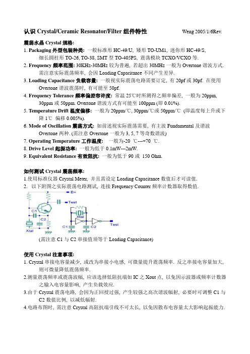
认识Crystal/Ceramic Resonator/Filter组件特性Weng 2005/1/6Rev.震荡水晶Crystal规格:1.Packaging外型包装种类:一般标准形HC-49/U, 矮形TO-UM1, 迷你形HC-49/S,细长圆柱形TO-26, TO-38, SMT型TO-405PS, 震荡模块TCXO/VCXO等.2. Frequency频率范围: 30KHz-30MHz较为普遍, 若超出30MHz一般为Overtone谐波方式.需注意实际震荡频率, 会因Loading Capacitance不同产生差异.3. Loading Capacitance负载容量: 一般视实际震荡电路需要订定, 有20pf或30pf. 在使用Overtone谐波震荡时, 有可能至50pf.4. Frequency Tolerance频率偏差容许度:常温25℃时所测得之频率偏差, 一般为20ppm,30ppm或50ppm. Overtone谐波方式有可能至100ppm (即0.01%).5. Temperature Drift温度偏移:一般为20ppm/℃, 30ppm/℃或50ppm/℃(即温度每上升或下降1℃偏移0.005%).6. Mode of Oscillation震荡方式:如前述视实际震荡需要, 有主波Fundamental及谐波Overtone两种. (需注意Overtone一般为3, 5, 7等奇数谐波)7. Operating Temperature工作温度:一般为-20 ℃---+70 ℃.8. Drive Level起振功率:一般为低于0.1mW---2mW.9. Equivalent Resistance有效阻抗:一般为低于90或150 Ohm.如何测试Crystal震荡频率:1.使用标准仪器Crystal Meter, 并且需设定Loading Capacitance数值后才可读值.2.以下附图之实际震荡电路测试, 连接Frequency Counter频率计数器取得数值.(需注意C1与C2串接值须等于Loading Capacitance)使用Crystal注意事项:1. Crystal串接电容量减少, 或改为串接小电感, 可微量提升震荡频率. 反之串接电容量加大,则可微量降低震荡频率.2.测量震荡频率或震荡波幅, 应该选择低阻抗端如IC之Xout点, 以免因示波器或频率计数器之输入电容量影响, 产生负载效应.3.由于Crystal震荡电路, 会因为正回授过强, 产生较强之高次谐波幅射, 必要时可调整C1与C2数值比例, 以减低幅射.4.电路布图时, 需注意Crystal高阻抗端引线不可太长, 以免因散布电容量太大影响起振能力.Ceramic Resonator规格:1.Packaging外型包装种类: 外型与一般Ceramic filter相同, 有2-Pin, 3-Pin及SMT型.2.Frequency频率范围:一般3.58MHz-50MHz较为普遍, SMT型16MHz-50 MHz3.Frequency Tolerance频率偏差容许度: 一般0.5%, 特定品0.3%.4.Temperature Drift温度偏移: 0.3% (-40 ℃---+85 ℃), 10 ppm/℃(-20 ℃---+85 ℃)5.Loading Capacitance负载容量: 一般30PF (4-6MHz), 20PF (8-10MHz), 15PF (16MHz),10P F(24MHz), 5PF (>30MHz).Specifying Quartz Crystals/appnotes.cfm/appnote_number/726This article explains in detail the specifications and characteristics of crystals and crystal oscillators. It is extremely useful as an aid in specifying crystals and working with crystal vendors. It covers every significant performance characteristics of crystals such as resonance frequency, resonance mode, load capacitance, series resistance, holder capacitance, motional inductance and capacitance, and drive level.Quartz crystals are available in a myriad of shapes and sizes, and can range widely in performance specifications. These specifications include resonance frequency, resonance mode, load capacitance, series resistance, holder capacitance, motional inductance and capacitance, and drive level. Understanding these parameters and how they relate to the crystal's performance will allow you to successfully specify crystals for your circuit application.A quartz crystal can be modeled as a series LRC circuit in parallel with a shunt capacitor. Figure 1 shows this generic circuit model.Figure 1. Generic crystal model (fundamental mode)Now let's look at each key performance specification in detail.Resonance FrequencyCrystals below 30MHz are often specified at the fundamental frequency, but above 30MHz they are typically specified as 3rd, 5th, or even 7th overtone (overtones occur only at odd multiples). It's important to know whether the oscillator is operating in fundamental or overtone mode. An overtone is similar in concept to a harmonic, with the exception that crystal oscillation overtones are not exact integer multiples of the fundamental. Selection of overtone is based upon using the lowest possible overtone that will result in a crystal fundamental frequency below 30MHz. The vendor calibrates a 3rd overtone crystal at the 3rd overtone, not the fundamental. For example, most crystal vendors will automatically give you a 3rd overtone 50MHz crystal if you don't specify fundamental mode or an overtone mode. If you plug a 50MHz 3rd overtone crystal into an oscillator that expects a fundamental-mode crystal, you are likely to have an oscillator running at 50/3 or 16.666MHz! If you don't know the frequency mode of your crystal, contact the designer or the manufacturer of the oscillator circuit.The reason crystal vendors provide overtone crystals is that the quartz material becomes thinner and thinner as frequency increases. Starting at about 30MHz, the quartz becomes so thin that it is hard to handle during the manufacturing process, and crystal vendors don't like to deal with thin crystals. One recent innovation in this area is the invention of inverted mesa crystals. Inverted mesa crystals can be manufactured with a thinner structure and thus can be reliably manufactured at higher fundamental-mode frequencies. This makes for less complex high-frequency oscillator designs and reduces component count by avoiding the need for external inductors/capacitors to induce the proper overtone oscillation mode from the crystal. Not all crystal vendors can provide inverted mesa technology; but, for the ones that can, they will be able to specify fundamental-mode crystals considerably higher than 30MHz. Remember that an overtone-mode crystal cannot be used in a fundamental-mode oscillator, and vice versa. It may oscillate but not at the correct frequency.Resonance ModeCrystals have two modes of resonance: parallel and series. All crystals exhibit both resonance modes. The oscillator circuit is calibrated for one or the other, but not both. For applications requiring no tighter than 100ppm frequency accuracy, this spec is usually not an issue. However, if you are attempting to control frequency (or time) to within 100ppm, the resonance-mode specification becomes important. The difference to the crystal vendor is in which mode the crystal is calibrated during manufacturing. The crystal vendor sets up an oscillator circuit with the crystal in a customer-specified series resonance or parallel resonance and calibrates the crystal. Figure 2 shows crystal impedance behavior versus frequency as well as the relative location of each resonance mode.Figure 2. Crystal impedance versus frequencyLoad CapacitanceLoad capacitance is an important specification when using parallel resonant oscillation mode. Referring to Figure 2, it can be seen that crystal parallel resonance mode is always above the series resonance frequency and is characterized by inductive reactance. In parallel resonance oscillation mode, the crystal's inductance (motional inductance) is in parallel with the oscillator's load capacitance, thereby forming an LC tank circuit. This LC determines the oscillator frequency. If your oscillator uses parallel resonance, the crystal vendor must know the load capacitance employed by the oscillator circuit. The load capacitance is simply the amount of external circuit capacitance in parallel with the crystal itself when it is placed in the oscillator circuit. The crystal vendor will then make sure that your crystal is calibrated at the factory using this same load capacitance. Vendors are flexible regarding load capacitance; ask them what range of load capacitance you can specify. Your oscillator should fall within the crystal vendor's acceptable range of load capacitance.With a series resonant crystal, you can ignore the load capacitance specification, because the motional inductance and motional capacitance of the crystal are the only LC components thatdetermine oscillation frequency.In Figure 2, the anti-resonance occurs when the net inductive component of the crystal model resonates with the crystal's internal holder capacitance. Anti-resonance is not used for oscillator designs.Series ResistanceSeries resistance is the effective resistive component in series with the LC model of the crystal itself (see Figure 1). Oscillator circuits can tolerate a certain degree of series resistance but not too much. A typical range is 25 ohms to 100 ohms for most crystals. The crystal vendor usually characterizes this resistance and specifies typical or maximum values for series resistance. Excessive crystal series resistance can lead to oscillator startup failure, so sufficient margin must be built into the oscillator design.An exception is 32.768KHz wristwatch crystals. Their series resistance can be in the tens of kilohms, so the oscillator circuit must be designed to accommodate this high series resistance. Failure to address this will result in a 32.768KHz oscillator that does not oscillate. Don't expect to use an oscillator designed for a 10MHz crystal with a 32.768KHz crystal; it won't work.Holder CapacitanceAll crystals have small electrodes that connect the crystal to the package pins. The electrodes form a shunt capacitance in parallel with the crystal's LC model, as shown in Figure 1. Depending on the crystal's size and package, the holder capacitance can vary. Typical values range from 2pF to 6pF. Some oscillators will not tolerate excessive holder capacitance. This is particularly true at higher frequencies as the reactance of the holder capacitance decreases. Make sure the crystal vendor's holder capacitance is within the allowable range for your oscillator. As a general rule, minimize the holder capacitance (the smaller, the better).Motional Inductance and CapacitanceMotional inductance and capacitance are specifications provided by the crystal vendor. They describe the L and C values that comprise the electrical LC model of the crystal. What is noteworthy about these values is the extreme ratio of L to C, which results in very large inductive and capacitive reactance values at the operating frequency. This is what gives a crystal its extraordinarily high "quality factor," also referred to as "Q" (Q being the ratio of energy stored to energy dissipated, also defined as the ratio of reactance to series resistance at the resonant frequency). For an LRC circuit, Q = 1/R * sq. rt. (L/C) (the derivation of this is beyond the scope of this article). A high Q is desirable. Higher Q values mean less frequency shift for a change in oscillator load capacitance and less shift due to other external factors such as oscillator supply voltage. Depending on your application, your oscillator circuit may or may not require specification of motional inductance and capacitance.Drive LevelThe power dissipated in the crystal must be limited or the quartz crystal can actually fail due to excessive mechanical vibration. Crystal characteristics also change with drive level due to nonlinear behavior. Analyze the oscillator design to determine the power dissipated in the crystal. Power dissipated is the product of crystal current squared times crystal series resistance. For a parallel resonant oscillator, the crystal current equals the RMS voltage across the load capacitor divided by the load capacitor's reactance at the oscillator frequency. For a series resonant crystal, the crystal current is the RMS voltage across the crystal divided by the crystal internal series resistance. The crystal manufacturer will specify maximum drive levels for a particular product line.Expect crystal usage to continue to increase as crystals find their way into more and more products that use microcontrollers, digital signal processors, and data converters. Crystal technology is also moving forward, resulting in better performance and lower costs. Though at first glance, crystals may seem simple elements that one merely plugs into the circuit, an analysis of the actual circuit model and an understanding of key parameters show them in a different light and also simplify the process of designing them into your next application. The following handy crystal specification worksheet will help you in specifying and ordering quartz crystals.Table 1. Crystal Specification Worksheet。

常用晶体管参数查询晶体管是一种用于放大、开关和调整电信号的电子元件,广泛应用于电子设备和通信系统中。
晶体管的各种参数对其性能影响很大,因此对于设计和选择晶体管的工程师来说,了解和查询常用晶体管参数非常重要。
下面将介绍几个常用的晶体管参数。
1. 最大工作频率(fmax):晶体管可以工作的最高频率。
这个参数对于高频通信和雷达应用非常重要,通常以GHz为单位。
2. 最大功率(Pmax):晶体管能够承受的最大功率。
这个参数通常以瓦特(W)为单位,并且与晶体管的封装和散热系统有关。
3.最大工作电压(VCEO):晶体管可以承受的最大集电极至发射极电压。
这个参数对于功率放大应用非常重要。
4. 最大工作电流(ICmax):晶体管可以承受的最大集电极电流。
这个参数对于功率放大和开关应用非常重要。
5. 饱和压降(VCEsat):晶体管在饱和状态下的集电极至发射极压降。
这个参数对于开关应用和数字逻辑电路非常重要。
6. 放大倍数(hfe或β):晶体管的放大倍数,即集电极电流与基极电流的比值。
这个参数对于放大应用非常重要。
7. 输入电阻(Rin):晶体管输入电阻,即基极电阻。
这个参数对于信号输入和电路匹配非常重要。
8. 输出电阻(Rout):晶体管输出电阻,即集电极电阻。
这个参数对于信号输出和电路匹配非常重要。
9.噪声系数(NF):晶体管的噪声性能,表示增益下降的程度。
这个参数对于接收机和低噪声放大器应用非常重要。
10.温度系数(TC):晶体管参数随温度变化的变化率。
这个参数对于在高温环境下的应用非常重要。

晶振知识大全(总17页) -CAL-FENGHAI.-(YICAI)-Company One1-CAL-本页仅作为文档封面,使用请直接删除晶振的定义: 晶振的英文名称为crystal. 石英晶体经精密切割磨削并镀上电极焊上引线做成,主要是为电路提供频率基准的元器件。
晶振的分类:1.按制作材料,分为石英晶振和陶瓷晶振。
石英晶振:利用石英晶体(二氧化硅的结晶体)的压电效应制成的一种谐振器件,它的基本结构大致是从一块石英晶体上按一定方位角切下薄片(简称为晶片,它可以是正方形、矩形或圆形等),在它的两个对应面上涂敷银层作为电极,在每个电极上各焊一根引线接到管脚上,再加上封装外壳就构成了石英晶体谐振器,简称为石英晶体或晶体、晶振。
其产品一般用金属外壳封装,也有用玻璃壳、陶瓷或塑料封装的。
陶瓷晶振:指用陶瓷外壳封装的晶振,跟石英晶振比起来精度要差一些,但成本也比较低,主要用在对频率精度要求不高的电子产品中。
陶瓷晶振就是晶体逆压电效应原理,陶瓷谐振器的工作原理就是既可以把电能转换为机械能,也可以把机械能转换为电能。
目前陶瓷谐振器的类型按照外形可以分为直插式和贴片式两中。
2. 从功能上分晶振分为无源晶振和有源晶振。
无源晶振即为石英晶体谐振器,而有源晶振即位石英晶体振荡器。
无源晶振只是个石英晶体片,使用时需匹配相应的电容、电感、电阻等外围电路才能工作,精度比晶振要低,但它不需要电源供电,有起振电路即可起振,一般有两个引脚,价格较低。
有源晶振内部含有石英晶体和匹配电容等外围电路,精度高、输出信号稳定,不需要设计外围电路、使用方便,但需要电源供电,有源晶振一般是四管脚封状,有电源、地线、振荡输出和一个空置端。
使用有源晶振时要特别注意,电源必须是稳压的且电源引线尽量短,并尽量与系统中使用晶振信号的芯片共地。
3、从封装形式上分有直插型(DIP)和贴片型(SMD)。
4、按谐振频率精度,分为高精度型、中精度型和普通型晶振。
5、按应用特性,分为串联谐振型晶振和并联谐振型晶振。

晶振指标参数介绍如下:
晶振(Crystal oscillator)是一种电子元器件,其指标参数主要包括以下几个方面:
1.频率(Frequency):晶振的频率通常用赫兹(Hz)表示,即每秒钟振荡的次数。
晶
振的频率决定了其在电子系统中的应用范围和精度。
2.稳定度(Stability):晶振的稳定度指其输出频率的变化范围,通常用单位百万分之一
(ppm)表示。
晶振的稳定度越高,其输出频率的变化范围就越小,输出频率就越稳定。
3.相位噪声(Phase noise):晶振的相位噪声指其输出频率随时间的变化,通常用分贝
(dBc/Hz)表示。
相位噪声越小,晶振输出的频率波动就越小,稳定性越好。
4.工作温度范围(Operating temperature range):晶振的工作温度范围指其能够正常
工作的温度范围,通常用摄氏度(℃)表示。
晶振的工作温度范围应该适应于所需应用环境的温度范围。
5.电源电压(Supply voltage):晶振的电源电压指其需要的电源电压,通常用伏特(V)
表示。
晶振的电源电压应该适应于所需应用环境的电源电压。
需要根据具体的应用需求来选择合适的晶振,以保证电路的性能和稳定性。
晶体管参数大全范文晶体管是现代电子设备中不可或缺的重要元件之一,它广泛用于各种电子电路中,从小型的家用电器到大型的计算机系统都离不开晶体管的应用。
在设计和选择晶体管时,我们需要了解一些重要的参数,以便正确地使用它们。
下面是一些常见的晶体管参数的详细介绍。
1.最大工作电压(VCEO):晶体管能够承受的最大工作电压。
超过这个电压,晶体管可能会损坏。
2.最大连续电流(IC):晶体管能够连续通过的最大电流。
当电流超过这个值时,晶体管可能会饱和或烧坏。
3.最大功率(P):晶体管能够承受的最大功率。
功率计算公式为P=VCE×IC,其中VCE为晶体管的电压降,IC为电流。
4.放大因子(β):晶体管输入电流与输出电流之间的比率。
即β=IC/IB,其中IB为输入基极电流。
5.漏电流(ICBO):当晶体管处于关闭状态时,流过集电极的电流。
这个参数应该尽可能小,以确保晶体管关闭时能达到较高的电阻。
6. 饱和电压(VCEsat):当晶体管处于饱和状态时的集电极和发射极之间的电压降。
这个参数应该尽可能小,以确保晶体管在饱和状态时提供最低的电压降。
7. 输入电阻(Rin):晶体管的输入端电阻。
这个参数应该尽量大,以减小输入信号对电路的影响。
8. 输出电阻(Rout):晶体管的输出端电阻。
这个参数应该尽量小,以提高输出信号的驱动能力。
9. 转移电导(gm):晶体管输出电流对输入电压的变化率。
转移电导越大,晶体管越容易放大信号。
10. 频率响应(ft):晶体管的最大工作频率。
超过这个频率,晶体管可能会出现频率衰减或信号失真的问题。
11.温度稳定性:晶体管在不同温度下的性能变化情况。
稳定性越好,晶体管的性能越可靠。
12.封装类型:晶体管的外壳类型。
常见的封装类型有TO-92、SOT-23、SOT-223等。
不同的封装类型适用于不同的应用场景。
总结:晶体管参数非常重要,它们直接影响到晶体管的性能和应用范围。
因此,在选择和使用晶体管时,我们应该仔细研究和理解这些参数,并根据具体的应用需求进行选择。
proteus晶振元件名称Proteus晶振元件名称晶振元件在电子设备中起着至关重要的作用,它是一种用于产生稳定频率的元件,被广泛应用于各种电子产品中。
在Proteus软件中,晶振元件也具有不同的名称和规格,下面将介绍几种常见的Proteus 晶振元件名称及其特点。
1. XTAL - 晶体振荡器XTAL是Proteus软件中常见的晶振元件名称,它代表晶体振荡器。
晶体振荡器是一种利用晶体的谐振性质产生稳定频率的元件。
在电子电路中,晶体振荡器常用于时钟信号的产生,确保电子设备能够按时运行。
2. CRYSTAL - 晶体振荡器CRYSTAL也是Proteus软件中常见的晶振元件名称,与XTAL类似,代表晶体振荡器。
晶体振荡器在电子设备中应用广泛,不仅用于时钟信号的产生,还可用于频率合成、通信系统等领域。
3. CRYSTAL OSCILLATOR - 晶体振荡器除了XTAL和CRYSTAL外,Proteus软件中还有一种晶振元件名称为CRYSTAL OSCILLATOR,即晶体振荡器。
晶体振荡器可分为被动晶振和主动晶振两种类型,被动晶振由晶体和振荡电路组成,主动晶振还包含放大电路。
4. XTAL OSCILLATOR - 晶体振荡器XTAL OSCILLATOR是Proteus软件中另一种常见的晶振元件名称,与CRYSTAL OSCILLATOR类似,代表晶体振荡器。
晶体振荡器的频率稳定性和精度较高,适用于对频率要求严格的电子设备中。
总的来说,Proteus软件中的晶振元件名称多样,代表着不同类型的晶体振荡器。
这些晶振元件在电子设备的设计和仿真中起着关键作用,能够提供稳定的时钟信号和频率源,确保电子设备的正常运行。
希望以上介绍能帮助大家更好地了解Proteus晶振元件的名称及其特点。
crystal在proteus中的名称Crystal在Proteus中的名称Crystal是一种非常常见的元件,它在电子电路中扮演着非常重要的角色。
在Proteus中,Crystal也是一种非常常见的元件,它被用来产生高精度的时钟信号,以确保电路的稳定性和可靠性。
在本文中,我们将详细介绍Crystal在Proteus中的名称以及它的作用。
在Proteus中,Crystal的名称为“XTAL”。
XTAL是Crystal的缩写,它代表着Crystal的英文单词“Crystal”。
在Proteus中,XTAL通常被用来产生高精度的时钟信号,以确保电路的稳定性和可靠性。
XTAL通常被用在微控制器、计算机、通信设备等高精度电子设备中,以确保它们的正常运行。
XTAL的工作原理非常简单。
它由两个相互振动的石英晶体组成,这两个晶体之间通过一个电容器相连。
当电压施加到电容器上时,晶体开始振动,产生高精度的时钟信号。
这个时钟信号可以被用来控制电路中的各种操作,例如计时、数据传输等。
在Proteus中,XTAL通常被用来模拟电路中的时钟信号。
它可以被连接到微控制器、计算机、通信设备等电子设备中,以确保它们的正常运行。
在Proteus中,XTAL的参数可以被设置,例如频率、电容器等。
这些参数可以被用来模拟不同的电子设备中的时钟信号,以确保电路的稳定性和可靠性。
XTAL是一种非常重要的元件,在Proteus中也是非常常见的。
它被用来产生高精度的时钟信号,以确保电路的稳定性和可靠性。
在Proteus中,XTAL的参数可以被设置,以模拟不同的电子设备中的时钟信号。
如果你是一名电子工程师或者学生,那么你一定会经常使用到XTAL这个元件。