
TL1240YQ1JCLR;中文规格书,Datasheet资料
- 格式:pdf
- 大小:84.97 KB
- 文档页数:2

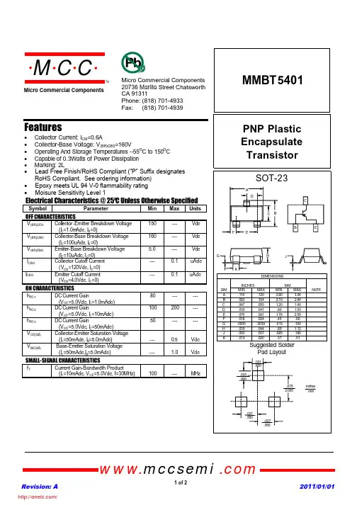
MMBT5401PNP Plastic Encapsulate TransistorFeatures• Collector Current:I CM =0.6A• Collector-Base Voltage:V (BR)CBO =160V• Operating And Storage Temperatures –55O C to 150O C • Capable of 0.3Watts of Power Dissipation • Marking:2LElectrical Characteristics @ 25OC Unless Otherwise SpecifiedSymbol ParameterMin Max Units OFF CHARACTERISTICSV (BR)CEO Coll e ctor -Emitter Breakdown Voltage (I C =1.0m Adc,I B =0)150--- Vdc V (BR)CBO Collector-Base Breakdown Voltage (I C =100uAdc,I E =0)160--- Vdc V (BR)EBO Emitter-Base Breakdown Voltage (I E =10uAdc,I C =0) 5.0--- VdcI CBO Collector Cutoff Current (V CB =120Vdc,I E =0)---0.1uAdcI EBOEmitter Cutoff Current (V EB =4.0Vdc,I C =0)---0.1uAdcON CHARACTERISTICSh FE-1DC Current Gain(V CE =5.0Vdc,I C =1.0mAdc)80------ h FE-2DC Current Gain(V CE =5.0Vdc,I C =10mAdc)100200--- h FE-3DC Current Gain(V CE =5.0Vdc,I C =50mAdc)50------V CE(sat)Collector-Emitter Saturation Voltage (I C =50mAdc,I B =5.0mAdc)---0.5Vdc V BE(sat)Base-Emitter Saturation Voltage (I C =50mAdc,I B =5.0mAdc)---1.0VdcSMALL-SIGNAL CHARACTERISTICSf TCurrent Gain-Bandwidth Product(I C =10mAdc,V CE =5.0Vdc, f=30MHz)100---MHzRevision: A 2011/01/01omp onents 20736Marilla Street Chatsworth! "# $ % ! "#Micro Commercial Componentswww.mccsemi .com1 of 2• Lead Free Finish/RoHS Compliant ("P" Suffix designates RoHS Compliant. See ordering information)• Epoxy meets UL 94 V-0 flammability rating • Moisure Sensitivity Level 1/Revision: A 2011/01/01Micro Commercial Componentswww.mccsemi .com2 of 23Ordering Information :***IMPORTANT NOTICE***Micro Commercial Components Corp. reserve s the right to make changes without further notice to any product herein to make corrections, modifications , enhancements , improvements , or other changes . Micro Commercial Components Corp . does not assume any liability arising out of the application or use of any product described herein; neither does it convey any license under its patent rights ,nor the rights of others . The user of products in such applications shall assume all risks of such use and will agree to hold Micro Commercial Components Corp . and all the companies whose products are represented on our website, harmless against all damages.***LIFE SUPPORT***MCC's products are not authorized for use as critical components in life support devices or systems without the express writtenapproval of Micro Commercial Components Corporation.***CUSTOMER AWARENESS***Counterfeiting of semiconductor parts is a growing problem in the industry. Micro Commercial Components (MCC) is taking strong measures to protect ourselves and our customers from the proliferation of counterfeit parts. MCC strongly encourages customers to purchase MCC parts either directly from MCC or from Authorized MCC Distributors who are listed by country on our web page cited below . Products customers buy either from MCC directly or from Authorized MCC Distributors are genuine parts, have full traceability, meet MCC's quality standards for handling and storage. MCC will not provide any warranty coverage or other assistance for parts bought from Unauthorized Sources. MCC is committed to combat this global problem and encourage our customers to do their part in stopping this practice by buying direct or from authorized distributors.DevicePackingPart Number-T PTape&Reel;3Kpcs/Reel/分销商库存信息: MICRO-COMMERICAL-CO MMBT5401-TP。
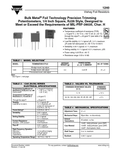
Document Number: 63053For any questions, contact: foil@1240Vishay Foil ResistorsBulk Metal ® Foil Technology Precision TrimmingPotentiometers, 1/4 Inch Square, RJ26 Style, Designed to Meet or Exceed the Requirements of MIL-PRF-39035, Char. HFEATURES•Temperature coefficient of resistance (TCR): ± 10 ppm/°C. (- 55 °C to + 150 °C ref. at + 25 °C);through the wiper 3); ± 25 ppm/°C (see table 2 for low values)•Load life stability: 0.1 % typical ΔR, 1.0 % maximum ΔR under full rated power at + 85 °C for 10000 h •Settability: 0.05 % typical; 0.1 % maximum•Setting stability: 0.1 % typical; 0.5 % maximum, ΔSS •Power rating: 0.25 W at + 85 °C •Resistance range: 5 Ω to 10 k ΩNote:* See Figure 1, next pageTABLE 1 - MODEL SELECTION *MODELTERMINATION STYLE AVERAGE WEIGHT (g)POWER RATING at + 85 °C AMBIENTNO. OF TURNS1240W-edge mount, top adjust0.40.25 W21 ± 2X-edge mount, side adjust P-horizontal mount, side adjustTABLE 2 -1240 (RJ26) SERIESELECTRICAL SPECIFICATIONSTemperature Coefficient of Resistance (TCR) 50 Ω to 10K End-to-end 2)± 10 ppm/°C maximum (- 55 °C to + 150 °C,+ 25 °C ref.)Temperature Coefficient of Resistance 5, 10 and 20 ΩThrough the wiper 3)± 20 ppm/°C ± 25 ppm/°CStabilityLoad life at 10000 h0.1 % typical ΔR 1.0 % maximum ΔR(under full rated power of 0.25 W at + 85 °C)Power Rating 4)0.25 W at + 85 °C Settability 0.05 % typical;0.1 % maximum Setting Stability 0.1 % typical;0.5 % maximum Contact Resistance Variation - CRV (noise)5) 3 Ω typical; 10 Ω maximum Hop-off0.25 % typical;1.0 % maximum High-Frequency Operation Rise time Inductance Capacitance1.0 ns without ringing 0.08 µH typical 0.5 pF typical Operating Temperature Range- 55 °C to + 150 °CTABLE 3 - VALUES VS. TOLERANCESSTANDARD RESISTANCE VALUES(in Ω)STANDARD TOLERANCE5, 10± 10 %20, 50, 100, 200, 500, 1K, 2K, 5K, 10K± 5 %TABLE 4 - MECHANICAL SPECIFICATIONSAdjustment Turns 21 ± 2Mechanical Stops Wiper idles - no discontinuity InternalTerminations All welded - no fluxCase Material1240X - diallyl-phthalate: green (DAP)1240W - diallyl-phthalate: green (DAP)1240P - thermoplastic: blackShaft Torque 3 oz. in. maximum Backlash0.005 % typical1240Vishay Foil ResistorsBulk Metal ® Foil Technology Precision Trimming Potentiometers, 1/4 Inch Square, RJ26 Style, Designed to Meet or Exceed the Requirements of MIL-PRF-39035, Char. H For any questions, contact: foil@Document Number: 63053Document Number: 63053For any questions, contact: foil@1240Bulk Metal ® Foil Technology Precision Trimming Potentiometers, 1/4 Inch Square, RJ26 Style, Designed to Meet or Exceed the Requirements of MIL-PRF-39035, Char. HVishay Foil Resistors Notes:1.Maximum is 1.0 % A.Q.L. standard for all specifications except TCR. (For TCR information, see notes 2 and 3.)2.Maximum TCR applies to the 3 σ (sigma) limit or 99.73 % of a production lot. (Measured end-to-end with wiper off the element.)3.Measurements of TCR through the wiper are influenced more by setting stability and the percentage of the total resistance in use (at the wiper) than by fundamental resistance change due to temperature alone. The parameter shown in Table 2 is a 2 s distribution typifying the behavior of the device when used with 40% or more of the total resistance in use.4.Derated linearly for full power at + 85 °C to zero (0) W at +150°C.See Figure 2 on previous page.5.Independent of resistance value. 3 W maximum available on special request.6.All ΔR’s are measured to the tolerance specified + 0.01 Ω.7.Whichever is greater.Special Available Options:Special markingBurn-in and screening operations.VISHAY TRIMMERS ARE INSPECTED100 % for:•Short-time overload(6.25 x rated power for 5 s on; and for 30 s off - 3 cycles)•Immersion•Resistance tolerance check •End resistance •Visual-mechanical•Dynamic tests for continuity, CRV By sample for:•TCR •DWVTABLE 5 - COMPARISONMIL-PRF-39035/3 CHARACTERISTIC H 6)MODEL 1240 MAXIMUM TEST GROUP I ConditioningContact resistance variation - CRV (noise)Immersion± 1.0 %± 3.0 % or 3 Ω7)No continuous stream of bubbles± 0.5 %3 Ω typical, 10 Ω maximum No continuous stream of bubbles TEST GROUP I aVisual and mechanicalActual effective electrical travel End resistanceDielectric withstanding voltage - DWV (atmospheric and barometric pressure)Insulation resistance Shaft torque Thermal shock Setting stability No failures 10 to 25 turns 2 % or 2 Ω7)Per MIL-STD-202, methods 301 and 105≥ 1000 M Ω3 oz. in. maximum± 1.0 %± 1.0 %No failures 21 ± 2 turns2 Ω for values ≤ 1 k Ω;5 Ω for values ≥ 2 k Ω;Per MIL-STD-202, methods 301 and 105> 1000 M Ω3 oz. in. maximum± 0.5 %± 0.5 %TEST GROUP II SolderabilityPer MIL-STD-202, method 208Per MIL-STD-202, method 208TEST GROUP IIIResistance temperature characteristic - TCR Moisture resistanceContact resistance variation - CRV (noise)± 0.005 % (± 50 ppm/°C)± 1.0 %3.0 % or 3 Ω7)± 0.001 % (± 10 ppm/°C)± 0.5 %3 Ω typical, 10 Ω maximum TEST GROUP IV Settability ShockSetting stability VibrationSetting stabilityContact resistance variation - CRV (noise)Salt spray± 1.0 %± 1.0 %± 1.0 %± 1.0 %± 1.0 %3.0 % or 3 Ω7)No corrosion ± 0.1 %± 0.5 %± 0.5 %± 0.5 %± 0.5 %3 Ω typical, 10 Ω maximumNo corrosion TEST GROUP V Solder heatLow-temperature operation Setting stabilityLow-temperature storage High-temperature exposure Setting stabilityContact resistance variation - CRV (noise)Integrity of shaft± 1.0 %± 1.0 %± 2.0 %± 1.0 %± 3.0 %± 2.0 %3 % or 3 Ω7)No loosening or breakage± 0.1 %± 0.5 %± 0.5 %± 0.5 %± 0.5 %± 0.5 %3 Ω typical, 10 Ω maximum No loosening or breakage TEST GROUP VIRotational life (200 cycles)Contact resistance variation - CRV (noise)T erminal strength ± 2.0 %3 % or 3 Ω7)2 lbs.± 2.0 %3 Ω typical, 10 Ω maximum2 lbs.TEST GROUP VIILife (2000 h) at + 85 °C Life (10000 h) at + 85 °C ± 3.0 %± 5.0 %± 0.1 % typical, ± 1.0 % maximum ± 0.1 % typical, ± 1.0 % maximumTEST GROUP VIII Solvent resistance No failuresNo failures1240Vishay Foil ResistorsBulk Metal ® Foil Technology Precision Trimming Potentiometers, 1/4 Inch Square, RJ26 Style, Designed to Meet or Exceed the Requirements of MIL-PRF-39035, Char. H For any questions, contact: foil@Document Number: 63053Note* Application engineering release: for non-standard requests, please contact application engineering.TABLE 6 - GLOBAL PART NUMBER INFORMATIONNEW GLOBAL PART NUMBER:Y4053500R000J0L (preferred part number format)DENOTES PRECISIONVALUE AER*YR = ΩK = k Ω0 = standard part, gold termination 1 - 999 = customPRODUCT CODE TOLERANCE PACKAGING 4053 = 1240W 5053 = 1240X 0053 = 1240PJ = ± 5 %K = ± 10 %L = bulk packFOR EXAMPLE: ABOVE GLOBAL ORDER Y4053 500R000 J 0 L:TYPE: 1240W VALUE: 500.0 ΩABSOLUTE TOLERANCE: ± 5.0 %AER: standard part, gold termination PACKAGING: bulk packHISTORICAL PART NUMBER:1240W 500R00J B (will continue to be used)1240W 500R00J B MODEL RESISTANCE VALUE TOLERANCE PACKAGING 1240W 1240X 1240P500R00 = 500.0 ΩJ = ± 5 %K = ± 10 %B = bulk pack05350R 00Y 4J 00LDisclaimer Legal Disclaimer NoticeVishayAll product specifications and data are subject to change without notice.Vishay Intertechnology, Inc., its affiliates, agents, and employees, and all persons acting on its or their behalf (collectively, “Vishay”), disclaim any and all liability for any errors, inaccuracies or incompleteness contained herein or in any other disclosure relating to any product.Vishay disclaims any and all liability arising out of the use or application of any product described herein or of any information provided herein to the maximum extent permitted by law. The product specifications do not expand or otherwise modify Vishay’s terms and conditions of purchase, including but not limited to the warranty expressed therein, which apply to these products.No license, express or implied, by estoppel or otherwise, to any intellectual property rights is granted by this document or by any conduct of Vishay.The products shown herein are not designed for use in medical, life-saving, or life-sustaining applications unless otherwise expressly indicated. Customers using or selling Vishay products not expressly indicated for use in such applications do so entirely at their own risk and agree to fully indemnify Vishay for any damages arising or resulting from such use or sale. Please contact authorized Vishay personnel to obtain written terms and conditions regarding products designed for such applications.Product names and markings noted herein may be trademarks of their respective owners.元器件交易网Document Number: 。

元器件交易网IMPORTANT NOTICETexas Instruments and its subsidiaries (TI) reserve the right to make changes to their products or to discontinueany product or service without notice, and advise customers to obtain the latest version of relevant informationto verify, before placing orders, that information being relied on is current and complete. All products are soldsubject to the terms and conditions of sale supplied at the time of order acknowledgement, including thosepertaining to warranty, patent infringement, and limitation of liability.TI warrants performance of its semiconductor products to the specifications applicable at the time of sale inaccordance with TI’s standard warranty. Testing and other quality control techniques are utilized to the extentTI deems necessary to support this warranty. Specific testing of all parameters of each device is not necessarilyperformed, except those mandated by government requirements.CERTAIN APPLICATIONS USING SEMICONDUCTOR PRODUCTS MAY INVOLVE POTENTIAL RISKS OFDEATH, PERSONAL INJURY, OR SEVERE PROPERTY OR ENVIRONMENTAL DAMAGE (“CRITICALAPPLICATIONS”). TI SEMICONDUCTOR PRODUCTS ARE NOT DESIGNED, AUTHORIZED, ORWARRANTED TO BE SUITABLE FOR USE IN LIFE-SUPPORT DEVICES OR SYSTEMS OR OTHERCRITICAL APPLICATIONS. INCLUSION OF TI PRODUCTS IN SUCH APPLICATIONS IS UNDERSTOOD TOBE FULLY AT THE CUSTOMER’S RISK.In order to minimize risks associated with the customer’s applications, adequate design and operatingsafeguards must be provided by the customer to minimize inherent or procedural hazards.TI assumes no liability for applications assistance or customer product design. TI does not warrant or representthat any license, either express or implied, is granted under any patent right, copyright, mask work right, or otherintellectual property right of TI covering or relating to any combination, machine, or process in which suchsemiconductor products or services might be or are used. TI’s publication of information regarding any thirdparty’s products or services does not constitute TI’s approval, warranty or endorsement thereof.Copyright © 1999, Texas Instruments Incorporated。