HMC5843-中文
- 格式:pdf
- 大小:445.10 KB
- 文档页数:19

/// -*- tab-width: 4; Mode: C++; c-basic-offset: 4; indent-tabs-mode: nil -*-#define THISFIRMWARE "ArduCopter V3.1-rc5"/*This program is free software: you can redistribute it and/or modifyit under the terms of the GNU General Public License as published bythe Free Software Foundation, either version 3 of the License, or(at your option) any later version.This program is distributed in the hope that it will be useful,but WITHOUT ANY WARRANTY; without even the implied warranty ofMERCHANTABILITY or FITNESS FOR A PARTICULAR PURPOSE. See theGNU General Public License for more details.You should have received a copy of the GNU General Public Licensealong with this program. If not, see </licenses/>.*//** ArduCopter Version 3.0* Creator: Jason Short* Lead Developer: Randy Mackay* Based on code and ideas from the Arducopter team: Pat Hickey, Jose Julio, Jani Hirvinen, Andrew Tridgell, Justin Beech, Adam Rivera, Jean-Louis Naudin, Roberto Navoni* Thanks to: Chris Anderson, Mike Smith, Jordi Munoz, Doug Weibel, James Goppert, Benjamin Pelletier, Robert Lefebvre, Marco Robustini** Special Thanks for Contributors (in alphabetical order by first name):** Adam M Rivera :Auto Compass Declination* Amilcar Lucas :Camera mount library* Andrew Tridgell :General development, Mavlink Support* Angel Fernandez :Alpha testing* Doug Weibel :Libraries* Christof Schmid :Alpha testing* Dani Saez :V Octo Support* Gregory Fletcher :Camera mount orientation math* Guntars :Arming safety suggestion* HappyKillmore :Mavlink GCS* Hein Hollander :Octo Support* Igor van Airde :Control Law optimization* Leonard Hall :Flight Dynamics, Throttle, Loiter and Navigation Controllers* Jonathan Challinger :Inertial Navigation* Jean-Louis Naudin :Auto Landing* Max Levine :Tri Support, Graphics* Jack Dunkle :Alpha testing* James Goppert :Mavlink Support* Jani Hiriven :Testing feedback* John Arne Birkeland :PPM Encoder* Jose Julio :Stabilization Control laws* Marco Robustini :Lead tester* Michael Oborne :Mission Planner GCS* Mike Smith :Libraries, Coding support* Oliver :Piezo support* Olivier Adler :PPM Encoder* Robert Lefebvre :Heli Support & LEDs* Sandro Benigno :Camera support** And much more so PLEASE PM me on DIYDRONES to add your contribution to the List** Requires modified "mrelax" version of Arduino, which can be found here:* /p/ardupilot-mega/downloads/list*////////////////////////////////////////////////////////////////////////////////// Header includes////////////////////////////////////////////////////////////////////////////////#include <math.h>#include <stdio.h>#include <stdarg.h>// Common dependencies#include <AP_Common.h>#include <AP_Progmem.h>#include <AP_Menu.h>#include <AP_Param.h>// AP_HAL#include <AP_HAL.h>#include <AP_HAL_AVR.h>#include <AP_HAL_AVR_SITL.h>#include <AP_HAL_PX4.h>#include <AP_HAL_FLYMAPLE.h>#include <AP_HAL_Linux.h>#include <AP_HAL_Empty.h>// Application dependencies#include <GCS_MAVLink.h> // MAVLink GCS definitions#include <AP_GPS.h> // ArduPilot GPS library#include <AP_GPS_Glitch.h> // 全球定位系统干扰保护库#include <DataFlash.h> // ArduPilot Mega Flash Memory Library#include <AP_ADC.h> // ArduPilot Mega Analog to Digital Converter Library#include <AP_ADC_AnalogSource.h>#include <AP_Baro.h>#include <AP_Compass.h> // ArduPilot Mega Magnetometer Library#include <AP_Math.h> // ArduPilot Mega Vector/Matrix math Library#include <AP_Curve.h> // Curve used to linearlise throttle pwm to thrust#include <AP_InertialSensor.h> // ArduPilot Mega Inertial Sensor (accel & gyro) Library #include <AP_AHRS.h>#include <APM_PI.h> // PI library#include <AC_PID.h> // PID library#include <RC_Channel.h> //遥控通道库#include <AP_Motors.h> // AP Motors library#include <AP_RangeFinder.h> // Range finder library#include <AP_OpticalFlow.h> // Optical Flow library#include <Filter.h> // Filter library#include <AP_Buffer.h> // APM FIFO Buffer#include <AP_Relay.h> // APM relay#include <AP_Camera.h> // Photo or video camera#include <AP_Mount.h> // Camera/Antenna mount#include <AP_Airspeed.h> // needed for AHRS build#include <AP_Vehicle.h> // needed for AHRS build#include <AP_InertialNav.h> // ArduPilot Mega inertial 导航 library#include <AC_WPNav.h> // ArduCopter waypoint navigation library#include <AP_Declination.h> // ArduPilot Mega Declination Helper Library#include <AC_Fence.h> // Arducopter Fence library#include <memcheck.h> // memory limit checker#include <SITL.h> // software in the loop support#include <AP_Scheduler.h> // 主循环调度程序#include <AP_RCMapper.h> // RC input mapping library#include <AP_Notify.h> // Notify library#include <AP_BattMonitor.h> // Battery monitor library#if SPRAYER == ENABLED#include <AC_Sprayer.h> // crop sprayer library// AP_HAL to Arduino compatibility layer#include "compat.h"// Configuration#include "defines.h"#include "config.h"#include "config_channels.h"// Local modules#include "Parameters.h"#include "GCS.h"//////////////////////////////////////////////////////////////////////////////// // cliSerial//////////////////////////////////////////////////////////////////////////////// // cliSerial isn't strictly necessary - it is an alias for hal.console. It may // be deprecated in favor of hal.console in later releases.static AP_HAL::BetterStream* cliSerial;// N.B. we need to keep a static declaration which isn't guarded by macros// at the top to cooperate with the prototype mangler.//////////////////////////////////////////////////////////////////////////////// // AP_HAL instance//////////////////////////////////////////////////////////////////////////////// const AP_HAL::HAL& hal = AP_HAL_BOARD_DRIVER;//////////////////////////////////////////////////////////////////////////////// // Parameters//////////////////////////////////////////////////////////////////////////////// //// Global parameters are all contained within the 'g' class.//static Parameters g;// main loop schedulerstatic AP_Scheduler scheduler;// AP_Notify instancestatic AP_Notify notify;//////////////////////////////////////////////////////////////////////////////// // prototypes//////////////////////////////////////////////////////////////////////////////// static void update_events(void);static void print_flight_mode(AP_HAL::BetterStream *port, uint8_t mode);//////////////////////////////////////////////////////////////////////////////// // Dataflash//////////////////////////////////////////////////////////////////////////////// #if CONFIG_HAL_BOARD == HAL_BOARD_APM2static DataFlash_APM2 DataFlash;#elif CONFIG_HAL_BOARD == HAL_BOARD_APM1static DataFlash_APM1 DataFlash;#elif CONFIG_HAL_BOARD == HAL_BOARD_AVR_SITL//static DataFlash_File DataFlash("/tmp/APMlogs");static DataFlash_SITL DataFlash;#elif CONFIG_HAL_BOARD == HAL_BOARD_PX4static DataFlash_File DataFlash("/fs/microsd/APM/logs");#elif CONFIG_HAL_BOARD == HAL_BOARD_LINUXstatic DataFlash_File DataFlash("logs");#elsestatic DataFlash_Empty DataFlash;#endif////////////////////////////////////////////////////////////////////////////////// the rate we run the main loop at////////////////////////////////////////////////////////////////////////////////static const AP_InertialSensor::Sample_rate ins_sample_rate = AP_InertialSensor::RATE_100HZ;////////////////////////////////////////////////////////////////////////////////// Sensors//////////////////////////////////////////////////////////////////////////////////// There are three basic options related to flight sensor selection.//// - Normal flight mode. Real sensors are used.// - HIL Attitude mode. Most sensors are disabled, as the HIL// protocol supplies attitude information directly.// - HIL Sensors mode. Synthetic sensors are configured that// supply data from the simulation.//// All GPS access should be through this pointer.static GPS *g_gps;static GPS_Glitch gps_glitch(g_gps);// flight modes convenience arraystatic AP_Int8 *flight_modes = &g.flight_mode1;#if HIL_MODE == HIL_MODE_DISABLED#if CONFIG_ADC == ENABLEDstatic AP_ADC_ADS7844 adc;#endif#if CONFIG_IMU_TYPE == CONFIG_IMU_MPU6000static AP_InertialSensor_MPU6000 ins;#elif CONFIG_IMU_TYPE == CONFIG_IMU_OILPANstatic AP_InertialSensor_Oilpan ins(&adc);#elif CONFIG_IMU_TYPE == CONFIG_IMU_SITLstatic AP_InertialSensor_HIL ins;#elif CONFIG_IMU_TYPE == CONFIG_IMU_PX4static AP_InertialSensor_PX4 ins;#elif CONFIG_IMU_TYPE == CONFIG_IMU_FLYMAPLEAP_InertialSensor_Flymaple ins;#elif CONFIG_IMU_TYPE == CONFIG_IMU_L3G4200DAP_InertialSensor_L3G4200D ins;#endif#if CONFIG_HAL_BOARD == HAL_BOARD_AVR_SITL// When building for SITL we use the HIL barometer and compass driversstatic AP_Baro_HIL barometer;static AP_Compass_HIL compass;static SITL sitl;#else// Otherwise, instantiate a real barometer and compass driver#if CONFIG_BARO == AP_BARO_BMP085static AP_Baro_BMP085 barometer;#elif CONFIG_BARO == AP_BARO_PX4static AP_Baro_PX4 barometer;#elif CONFIG_BARO == AP_BARO_MS5611#if CONFIG_MS5611_SERIAL == AP_BARO_MS5611_SPIstatic AP_Baro_MS5611 barometer(&AP_Baro_MS5611::spi);#elif CONFIG_MS5611_SERIAL == AP_BARO_MS5611_I2Cstatic AP_Baro_MS5611 barometer(&AP_Baro_MS5611::i2c);#else#error Unrecognized CONFIG_MS5611_SERIAL setting.#endif#endif#if CONFIG_HAL_BOARD == HAL_BOARD_PX4static AP_Compass_PX4 compass;#elsestatic AP_Compass_HMC5843 compass;#endif#endif// real GPS selection#if GPS_PROTOCOL == GPS_PROTOCOL_AUTOAP_GPS_Auto g_gps_driver(&g_gps);#elif GPS_PROTOCOL == GPS_PROTOCOL_NMEAAP_GPS_NMEA g_gps_driver;#elif GPS_PROTOCOL == GPS_PROTOCOL_SIRFAP_GPS_SIRF g_gps_driver;#elif GPS_PROTOCOL == GPS_PROTOCOL_UBLOXAP_GPS_UBLOX g_gps_driver;#elif GPS_PROTOCOL == GPS_PROTOCOL_MTKAP_GPS_MTK g_gps_driver;#elif GPS_PROTOCOL == GPS_PROTOCOL_MTK19AP_GPS_MTK19 g_gps_driver;#elif GPS_PROTOCOL == GPS_PROTOCOL_NONEAP_GPS_None g_gps_driver;#else#error Unrecognised GPS_PROTOCOL setting.#endif // GPS PROTOCOLstatic AP_AHRS_DCM ahrs(&ins, g_gps);#elif HIL_MODE == HIL_MODE_SENSORS// sensor emulatorsstatic AP_ADC_HIL adc;static AP_Baro_HIL barometer;static AP_Compass_HIL compass;static AP_GPS_HIL g_gps_driver;static AP_InertialSensor_HIL ins;static AP_AHRS_DCM ahrs(&ins, g_gps);#if CONFIG_HAL_BOARD == HAL_BOARD_AVR_SITL// When building for SITL we use the HIL barometer and compass drivers static SITL sitl;#endif#elif HIL_MODE == HIL_MODE_ATTITUDEstatic AP_ADC_HIL adc;static AP_InertialSensor_HIL ins;static AP_AHRS_HIL ahrs(&ins, g_gps);static AP_GPS_HIL g_gps_driver;static AP_Compass_HIL compass; // never usedstatic AP_Baro_HIL barometer;#if CONFIG_HAL_BOARD == HAL_BOARD_AVR_SITL// When building for SITL we use the HIL barometer and compass driversstatic SITL sitl;#endif#else#error Unrecognised HIL_MODE setting.#endif // HIL MODE////////////////////////////////////////////////////////////////////////////////// Optical flow sensor////////////////////////////////////////////////////////////////////////////////#if OPTFLOW == ENABLEDstatic AP_OpticalFlow_ADNS3080 optflow;#elsestatic AP_OpticalFlow optflow;#endif////////////////////////////////////////////////////////////////////////////////// GCS selection////////////////////////////////////////////////////////////////////////////////static GCS_MAVLINK gcs0;static GCS_MAVLINK gcs3;////////////////////////////////////////////////////////////////////////////////// SONAR selection//////////////////////////////////////////////////////////////////////////////////ModeFilterInt16_Size3 sonar_mode_filter(1);#if CONFIG_SONAR == ENABLEDstatic AP_HAL::AnalogSource *sonar_analog_source;static AP_RangeFinder_MaxsonarXL *sonar;#endif////////////////////////////////////////////////////////////////////////////////// User variables////////////////////////////////////////////////////////////////////////////////#ifdef USERHOOK_VARIABLES#include USERHOOK_VARIABLES#endif////////////////////////////////////////////////////////////////////////////////// Global variables/////////////////////////////////////////////////////////////////////////////////* Radio values* Channel assignments* 1 Ailerons (rudder if no ailerons)* 2 Elevator* 3 Throttle* 4 Rudder (if we have ailerons)* 5 Mode - 3 position switch* 6 User assignable* 7 trainer switch - sets throttle nominal (toggle switch), sets accels to Level (hold >1 second)* 8 TBD* Each Aux channel can be configured to have any of the available auxiliary functions assigned to it.* See libraries/RC_Channel/RC_Channel_aux.h for more information*///Documentation of GLobals:static union {struct {uint8_t home_is_set : 1; // 0uint8_t simple_mode : 2; // 1,2 // This is the state of simple mode : 0 = disabled ; 1 = SIMPLE ;2 = SUPERSIMPLEuint8_t pre_arm_rc_check : 1; // 3 // true if rc input pre-arm checks have been completed successfully uint8_t pre_arm_check : 1; // 4 // true if all pre-arm checks (rc, accel calibration, gps lock) have been performeduint8_t auto_armed : 1; // 5 // stops auto missions from beginning until throttle is raised uint8_t logging_started : 1; // 6 // true if dataflash logging has starteduint8_t do_flip : 1; // 7 // Used to enable flip codeuint8_t takeoff_complete : 1; // 8uint8_t land_complete : 1; // 9 // true if we have detected a landinguint8_t new_radio_frame : 1; // 10 // Set true if we have new PWM data to act on from the Radio uint8_t CH7_flag : 2; // 11,12 // ch7 aux switch : 0 is low or false, 1 is center or true, 2 is highuint8_t CH8_flag : 2; // 13,14 // ch8 aux switch : 0 is low or false, 1 is center or true, 2 is highuint8_t usb_connected : 1; // 15 // true if APM is powered from USB connectionuint8_t yaw_stopped : 1; // 16 // Used to manage the Yaw hold capabilitiesuint8_t disable_stab_rate_limit : 1; // 17 // disables limits rate request from the stability controlleruint8_t rc_receiver_present : 1; // 18 // true if we have an rc receiver present (i.e. if we've ever received an update};uint32_t value;} ap;////////////////////////////////////////////////////////////////////////////////// Radio////////////////////////////////////////////////////////////////////////////////// This is the state of the flight control system// There are multiple states defined such as STABILIZE, ACRO,static int8_t control_mode = STABILIZE;// Used to maintain the state of the previous control switch position// This is set to -1 when we need to re-read the switchstatic uint8_t oldSwitchPosition;static RCMapper rcmap;// receiver RSSIstatic uint8_t receiver_rssi;////////////////////////////////////////////////////////////////////////////////// Failsafe////////////////////////////////////////////////////////////////////////////////static struct {uint8_t rc_override_active : 1; // 0 // true if rc control are overwritten by ground stationuint8_t radio : 1; // 1 // A status flag for the radio failsafeuint8_t battery : 1; // 2 // A status flag for the battery failsafeuint8_t gps : 1; // 3 // A status flag for the gps failsafeuint8_t gcs : 1; // 4 // A status flag for the ground station failsafeint8_t radio_counter; // number of iterations with throttle below throttle_fs_valueuint32_t last_heartbeat_ms; // the time when the last HEARTBEAT message arrived from a GCS - used for triggering gcs failsafe} failsafe;////////////////////////////////////////////////////////////////////////////////// Motor Output////////////////////////////////////////////////////////////////////////////////#if FRAME_CONFIG == QUAD_FRAME#define MOTOR_CLASS AP_MotorsQuad#elif FRAME_CONFIG == TRI_FRAME#define MOTOR_CLASS AP_MotorsTri#elif FRAME_CONFIG == HEXA_FRAME#define MOTOR_CLASS AP_MotorsHexa#elif FRAME_CONFIG == Y6_FRAME#define MOTOR_CLASS AP_MotorsY6#elif FRAME_CONFIG == OCTA_FRAME#define MOTOR_CLASS AP_MotorsOcta#elif FRAME_CONFIG == OCTA_QUAD_FRAME#define MOTOR_CLASS AP_MotorsOctaQuad#elif FRAME_CONFIG == HELI_FRAME#define MOTOR_CLASS AP_MotorsHeli#else#error Unrecognised frame type#endif#if FRAME_CONFIG == HELI_FRAME // helicopter constructor requires more argumentsstatic MOTOR_CLASS motors(&g.rc_1, &g.rc_2, &g.rc_3, &g.rc_4, &g.rc_8, &g.heli_servo_1, &g.heli_servo_2,&g.heli_servo_3, &g.heli_servo_4);#elif FRAME_CONFIG == TRI_FRAME // tri constructor requires additional rc_7 argument to allow tail servo reversing static MOTOR_CLASS motors(&g.rc_1, &g.rc_2, &g.rc_3, &g.rc_4, &g.rc_7);#elsestatic MOTOR_CLASS motors(&g.rc_1, &g.rc_2, &g.rc_3, &g.rc_4);#endif////////////////////////////////////////////////////////////////////////////////// PIDs////////////////////////////////////////////////////////////////////////////////// This is a convienience accessor for the IMU roll rates. It's currently the raw IMU rates// and not the adjusted omega rates, but the name is stuckstatic Vector3f omega;// This is used to hold radio tuning values for in-flight CH6 tuningfloat tuning_value;// used to limit the rate that the pid controller output is logged so that it doesn't negatively affect performance static uint8_t pid_log_counter;////////////////////////////////////////////////////////////////////////////////// LED output////////////////////////////////////////////////////////////////////////////////// Blinking indicates GPS statusstatic uint8_t copter_leds_GPS_blink;// Blinking indicates battery statusstatic uint8_t copter_leds_motor_blink;// Navigation confirmation blinksstatic int8_t copter_leds_nav_blink;////////////////////////////////////////////////////////////////////////////////// GPS variables////////////////////////////////////////////////////////////////////////////////// This is used to scale GPS values for EEPROM storage// 10^7 times Decimal GPS means 1 == 1cm// This approximation makes calculations integer and it's easy to readstatic const float t7 = 10000000.0;// We use atan2 and other trig techniques to calaculate angles// We need to scale the longitude up to make these calcs work// to account for decreasing distance between lines of longitude away from the equatorstatic float scaleLongUp = 1;// Sometimes we need to remove the scaling for distance calcsstatic float scaleLongDown = 1;////////////////////////////////////////////////////////////////////////////////// Location & Navigation////////////////////////////////////////////////////////////////////////////////// This is the angle from the copter to the next waypoint in centi-degreesstatic int32_t wp_bearing;// The original bearing to the next waypoint. used to point the nose of the copter at the next waypoint static int32_t original_wp_bearing;// The location of home in relation to the copter in centi-degreesstatic int32_t home_bearing;// distance between plane and home in cmstatic int32_t home_distance;// distance between plane and next waypoint in cm.static uint32_t wp_distance;// navigation mode - options include NAV_NONE, NAV_LOITER, NAV_CIRCLE, NAV_WPstatic uint8_t nav_mode;// Register containing the index of the current navigation command in the mission scriptstatic int16_t command_nav_index;// Register containing the index of the previous navigation command in the mission script// Used to manage the execution of conditional commandsstatic uint8_t prev_nav_index;// Register containing the index of the current conditional command in the mission scriptstatic uint8_t command_cond_index;// Used to track the required WP navigation information// options include// NAV_ALTITUDE - have we reached the desired altitude?// NAV_LOCATION - have we reached the desired location?// NAV_DELAY - have we waited at the waypoint the desired time?static float lon_error, lat_error; // Used to report how many cm we are from the next waypoint or loiter target positionstatic int16_t control_roll;static int16_t control_pitch;static uint8_t rtl_state; // records state of rtl (initial climb, returning home, etc)static uint8_t land_state; // records state of land (flying to location, descending)////////////////////////////////////////////////////////////////////////////////// Orientation(方向)////////////////////////////////////////////////////////////////////////////////// Convienience accessors for commonly used trig functions. These values are generated// by the DCM through a few simple equations. They are used throughout the code where cos and sin// would normally be used.// The cos values are defaulted to 1 to get a decent initial value for a level statestatic float cos_roll_x = 1.0;static float cos_pitch_x = 1.0;static float cos_yaw = 1.0;static float sin_yaw;static float sin_roll;static float sin_pitch;////////////////////////////////////////////////////////////////////////////////// SIMPLE Mode////////////////////////////////////////////////////////////////////////////////// Used to track the orientation of the copter for Simple mode. This value is reset at each arming// or in SuperSimple mode when the copter leaves a 20m radius from home.static float simple_cos_yaw = 1.0;static float simple_sin_yaw;static int32_t super_simple_last_bearing;static float super_simple_cos_yaw = 1.0;static float super_simple_sin_yaw;// Stores initial bearing when armed - initial simple bearing is modified in super simple mode so not suitable static int32_t initial_armed_bearing;////////////////////////////////////////////////////////////////////////////////// Rate contoller targets////////////////////////////////////////////////////////////////////////////////static uint8_t rate_targets_frame = EARTH_FRAME; // indicates whether rate targets provided in earth or body framestatic int32_t roll_rate_target_ef;static int32_t pitch_rate_target_ef;static int32_t yaw_rate_target_ef;static int32_t roll_rate_target_bf; // body frame roll rate targetstatic int32_t pitch_rate_target_bf; // body frame pitch rate targetstatic int32_t yaw_rate_target_bf; // body frame yaw rate target////////////////////////////////////////////////////////////////////////////////// Throttle(风门,调节) variables////////////////////////////////////////////////////////////////////////////////static int16_t throttle_accel_target_ef; // earth frame throttle acceleration targetstatic bool throttle_accel_controller_active; // true when accel based throttle controller is active, false when higher level throttle controllers are providing throttle output directlystatic float throttle_avg; // g.throttle_cruise as a floatstatic int16_t desired_climb_rate; // pilot desired climb rate - for logging purposes onlystatic float target_alt_for_reporting; // target altitude in cm for reporting (logs and ground station)////////////////////////////////////////////////////////////////////////////////// ACRO(高) Mode////////////////////////////////////////////////////////////////////////////////// Used to control Axis lockstatic int32_t acro_roll; // desired roll angle while sport modestatic int32_t acro_roll_rate; // desired roll rate while in acro modestatic int32_t acro_pitch; // desired pitch angle while sport modestatic int32_t acro_pitch_rate; // desired pitch rate while acro modestatic int32_t acro_yaw_rate; // desired yaw rate while acro modestatic float acro_level_mix; // scales back roll, pitch and yaw inversely proportional to input from pilot// Filters#if FRAME_CONFIG == HELI_FRAME//static LowPassFilterFloat rate_roll_filter; // Rate Roll filter//static LowPassFilterFloat rate_pitch_filter; // Rate Pitch filter#endif // HELI_FRAME////////////////////////////////////////////////////////////////////////////////// Circle Mode / Loiter(走停) control////////////////////////////////////////////////////////////////////////////////Vector3f circle_center; // circle position expressed in cm from home location. x = lat, y = lon// angle from the circle center to the copter's desired location. Incremented at circle_rate / secondstatic float circle_angle;// the total angle (in radians) travelledstatic float circle_angle_total;// deg : how many times to circle as specified by mission commandstatic uint8_t circle_desired_rotations;static float circle_angular_acceleration; // circle mode's angular accelerationstatic float circle_angular_velocity; // circle mode's angular velocitystatic float circle_angular_velocity_max; // circle mode's max angular velocity// How long we should stay in Loiter Mode for mission scripting (time in seconds)static uint16_t loiter_time_max;// How long have we been loitering - The start time in millisstatic uint32_t loiter_time;////////////////////////////////////////////////////////////////////////////////// CH7 and CH8 save waypoint(航路点) control////////////////////////////////////////////////////////////////////////////////// This register tracks the current Mission Command index when writing// a mission using Ch7 or Ch8 aux switches in flightstatic int8_t aux_switch_wp_index;////////////////////////////////////////////////////////////////////////////////// Battery Sensors////////////////////////////////////////////////////////////////////////////////static AP_BattMonitor battery;////////////////////////////////////////////////////////////////////////////////// Altitude////////////////////////////////////////////////////////////////////////////////// The (throttle) controller desired altitude in cmstatic float controller_desired_alt;// The cm we are off in altitude from next_WP.alt – Positive value means we are below the WP static int32_t altitude_error;// The cm/s we are moving up or down based on filtered data - Positive = UPstatic int16_t climb_rate;// The altitude as reported by Sonar in cm – Values are 20 to 700 generally.static int16_t sonar_alt;static uint8_t sonar_alt_health; // true if we can trust the altitude from the sonarstatic float target_sonar_alt; // desired altitude in cm above the ground// The altitude as reported by Baro in cm – Values can be quite highstatic int32_t baro_alt;static int16_t saved_toy_throttle;////////////////////////////////////////////////////////////////////////////////// flight modes////////////////////////////////////////////////////////////////////////////////// Flight modes are combinations of Roll/Pitch, Yaw and Throttle control modes// Each Flight mode is a unique combination of these modes//// The current desired control scheme for Yawstatic uint8_t yaw_mode;// The current desired control scheme for roll and pitch / navigationstatic uint8_t roll_pitch_mode;// The current desired control scheme for altitude holdstatic uint8_t throttle_mode;////////////////////////////////////////////////////////////////////////////////// flight specific////////////////////////////////////////////////////////////////////////////////// An additional throttle added to keep the copter at the same altitude when banking。
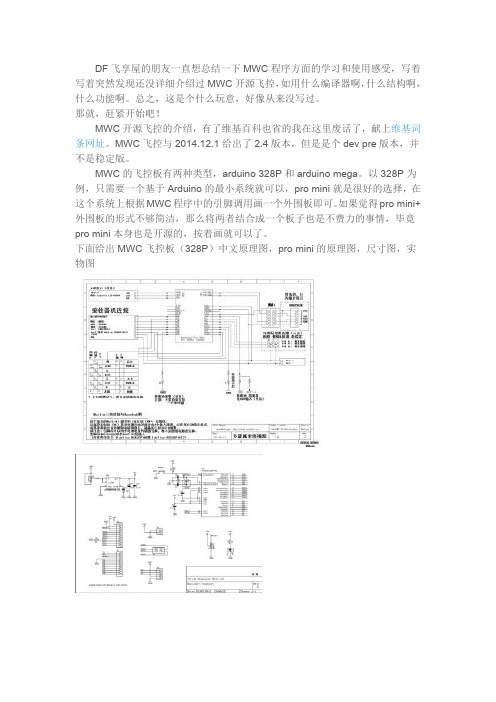
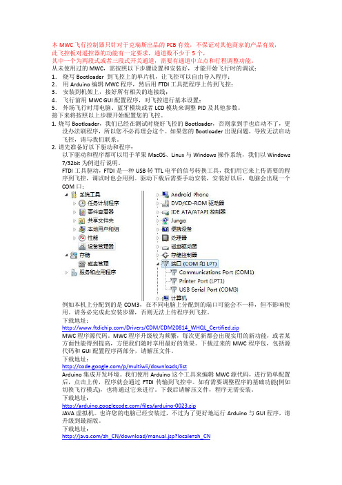
本MWC飞行控制器只针对于克瑞斯出品的PCB有效,不保证对其他商家的产品有效,此飞控板对遥控器的功能有一定要求,通道数不少于5个,其中一个为两段式或者三段式开关通道,需要有通道中立点和行程调整功能。
从未使用过的MWC,需按照以下步骤设置和安装好,才能开始飞行时的调试:1.烧写Bootloader 到飞控上的单片机,让飞控可以自由导入程序;2.用Arduino编辑MWC程序,然后用FTDI工具把程序上传到飞控;3.安装到机架上,接好所有相关的连接线;4.飞行前用MWC GUI配置程序,对飞控进行基本设置;5.外场飞行时用电脑、蓝牙模块或者LCD模块来调整PID及其他参数。
接下来将按照以上步骤开始配置您的飞控。
1.烧写Bootloader,我们已经在测试时烧好飞控的Bootloader,否则拿到手也启动不了,更没办法刷程序,所以您不必再理会这个。
如果您的Bootloader出现问题,导致无法启动飞控,请与我们联系。
2.请先准备好以下驱动和程序:以下驱动和程序都可以用于苹果MacOS、Linux与Windows操作系统,我们以Windows 7/32bit为例进行说明。
FTDI工具驱动,FTDI是一种USB转TTL电平的信号转换工具,我们用它来上传需要的程序到飞控,调试时也会用到。
驱动下载后需要手动安装,安装好以后,电脑会出现一个COM口:例如本机上分配到的是COM3,在不同电脑上分配到的端口可能会不一样,但不影响使用。
请务必完成此安装步骤,否则无法上传程序到飞控。
下载地址:/Drivers/CDM/CDM20814_WHQL_Certified.zipMWC程序源代码。
MWC程序升级较为频繁,每次更新都会出现实用的新功能,或者某方面性能得到提高,方便我们随时享用最好的效果。
下载过来的MWC程序包,包括源代码和GUI配置程序两部分,请解压文件。
下载地址:/p/multiwii/downloads/listArduino集成开发环境。


2. 使用HMC5883L能不能不用加速度传感器就能计算出航向?是的,不用加速度传感器就可以计算出航向。
但是,传感器必须保证是水平的,也就是,俯仰角与滚转角都为零。
这样,在水平面上的的三个轴中只有两个会被用到。
3.如何通过软件设置来识别板上应用的传感器是为HMC5843还是HMC5883L?我们不能通过其相同的识别寄存次来识别传感器的类型,但是可以通过下述方式进行识别:1)向配置寄存器A写入“01100000”;然后再进行读取;2)如果其反馈值还是为“01100000”,则该传感器为HMC5883L,反之.4. 为什么需要加速度传感器?如果罗盘不是水平的,就需要加速度传感器来纠正由于倾斜引起的误差。
或者,Honeywell提供了一体化解决方案HMC6343作为另外一种选择。
HMC6343内置3轴加速度传感器,具备倾斜补偿的航向输出,封装在9×9×1.9mm的芯片中。
5.HMC5883L Set/Reset回路所起到的作用是什么?该回路是Honeywell的专利设计,其在每次数据测量之前能够进行一个自动消磁的作用,以消除设备本身存在的offset,从而实现传感器在一个“纯净”的磁场进行测试.6.HMC5883L能够降低“噪音”干扰吗?是的,该款产品内部有取点取平均值的功能-它能够取值2,4,8个点的读数进行平均后再输出从而降低“噪音”的影响并且不会对高频率的信号识别产生影响;如下图分析所示:CONFIDENTIAL | Navigation Hong Kong Limited. All Rights Reserved7.如何判定传感器的好坏?可以通过设置HMC5883L的寄存器以启动传感器self-test的功能从而实现对于传感器好坏的判定.设置自测条件:Gain=5,正偏置模式,单一测量状态;获得数据结果:三轴所读取数据在243到575.8.如果未设置self-test模块的启动,如何判定传感器的好坏?如果未进行自测,那么可以从传感器所采集的数据来进行分析但首先要将各个轴的Gain值进行调整测试采集,如果传感器一直所采集的数据接近为零,则说明该传感器已经损坏或者焊锡出现虚焊和假焊现象.9.如何判定HMC5883L在PCB板上的位置是否可行的?将已经布局在板上的传感器采集到的原始数据转换为十进制的数据进行分析,看各轴数据的分布形状是否呈椭圆或者近似圆的分布.10.PCB layout时应该注意的方面有哪些?在传感器周围不应该有比较大的带磁物质或者通过大电流的线路,对于蜂鸣器以及含铁物件尽量保持比较远的距离.对于线宽间距设计建议如下:1. Bottom Layer –a. Increase the distance between HMC5883 and the adjacentcomponents. If possible, keep at least 2~3 mm away.b. Route pin 2 VDD trace away from the sensor (>1mm away).c. Increase pin 10 to C1 cap trace width (~0.3 mm).d. Increase pin 8 and 12 to C2 trace width (~0.3 mm).2. Layer 9 –a. Re-route traces for VDDIO and Set/Reset to go around thesensor. There should be no current carrying trace directlyunder the sensor in any layer.b. If this is power or ground plane, remove copper area directlyunder the sensor. This is to reduce any possible currentgenerated magnetic noise.CONFIDENTIAL | Navigation Hong Kong Limited. All Rights Reserveddirectly the sensor. This is to reduce any possible currentgenerated magnetic noise.3. Layer 5~8 – If this is power or ground plane, remove copperarea directly under the sensor. This is to reduce any possiblecurrent generated magnetic noise.4. Layer 4 –Re-route traces to go around the sensor. Same reasonas9a.5. Layer 2~3 – Same as layer 5~8.6. Top Layer – Remove components and traces directly under thesensor. There should be no ferrous material and currentcarrying traces directly under the sensor in any layer.11. HMC5883L是否支持手动焊接?HMC5883L并不推荐手工焊接,如必须使用,需注意下述两方面:1)锡膏最高温度不能超过315℃,IC不能加热时间过长;2)如果IC未保持在持续的干燥环境下,那么在封装之前必须进行烘烤,因为IC对湿度比较灵敏(MSL3)建议使用最高温度为260℃的Reflow流程进行焊接。
74HC573八进制3态非反转透明锁存器高性能硅门CMOS器件SL74HC573跟LS/AL573的管脚一样。
器件的输入是和标准CMOS输出兼容的;加上拉电阻,他们能和LS/ALSTTL输出兼容。
当锁存使能端为高时,这些器件的锁存对于数据是透明的(也就是说输出同步)。
当锁存使能变低时,符合建立时间和保持时间的数据会被锁存。
×输出能直接接到CMOS,NMOS和TTL接口上×操作电压范围:2.0V~6.0V×低输入电流:1.0uA×CMOS器件的高噪声抵抗特性管腿安排:功能表:输入输出输出使能锁存使能D Q L H H HL H L LL L X 不变H X X ZX=不用关心Z=高阻抗74HC573*最大值范围是指超过这个值,将损害器件。
操作最好在下面的推荐操作条件下。
+额定功率的下降——PDIP:-10mW/℃,65℃~125℃SOIC:-7 mW/℃,65℃~125℃这个器件带有保护电路,以免被高的静态电压或电场损坏。
然而,对于高阻抗电路,必须要采取预防以免工作在任何高于最大值范围的条件下工作。
V IN和V OUT 应该被约束在GND≤(V IN或V OUT)≤VCC。
不用的输入管腿必须连接总是连接到一个适合的逻辑电压电平(也就是GND 或者V CC)。
不用的输出管腿必须悬空。
AC电子特性(CL=50pF,输入tr=tf=6.0ns):符号参数VCCV 限制条件单位25℃~-55℃≤85≤125℃℃t SU 输入D到锁存使能最小建立时间(图4)2.04.56.05010965 7513 1511 13nst h 锁存使能到输入D最小保持时间(图4)2.04.56.05555 55 55 5nst W 锁存使能的最小脉宽(图2) 2.04.56.075151395 11019 2216 19nst r,t f 最大输入上升沿和下降沿时序(图1)2.04.56.010005004001000 1000500 500400 400nst PZH,t PZL 输出使能到Q最大延迟(图 3和图6)2.04.56.0150302619048332254538nst TLH,t THL 任何输出的最大输出延迟(图1和图5)2.04.56.0601210751513901815nsC IN 最大输入电容-10 10 10 pF C OUT 最大三态输出电容(在高阻态下的输出)-15 15 15 pFC PD 功耗电容(使能所有输出)用于确定没有负载时的动态功耗:典型在25℃,VCC=5V条件下pF23时序要求(C L=50pF,输入):74HC573逻辑74HC573。
生物磁场强度测定仪作者:徐哲刘姣张祥雪来源:《现代电子技术》2013年第12期摘要:生物磁场强度测定仪用于测定趋磁细菌产生的磁场,其硬件部分包含了磁场传感器、微控制器、显示部件、输入部件和实时时钟等,微控制器通过对磁场传感器配套的ASIC 进行读取获得当前方向磁场的强度,通过一定的运算后由直观的人机界面显示出来,并可通过微控制器的串口和上位机建立连接进行数据的传输。
该系统用于磁场强度的测量可达到0.01 G,功耗小,显示直观。
关键词:磁场强度; HMC5843;趋磁细菌; STC89C516RD+中图分类号: TN911⁃34 文献标识码: A 文章编号: 1004⁃373X(2013)12⁃0029⁃02地震往往给个人和社会带来严重的损失,如何准确地预测地震,减小地震造成的危害,一直是亟待解决的问题。
但是就现在来说,不管国内还是国际上,地震预测仪器的研发仍在探索阶段。
用于测定趋磁细菌磁场强度的生物磁场测定仪是一个典型的单片机系统。
地球磁场的磁场强度很低,利用趋磁细菌的生物特性可以测量和放大地磁场信号有利于研究地震前异常地磁场的变化,以便将其更加广泛的应用。
1 生物磁场强度测定仪1.1 系统框图及设计原理整个系统中前端的磁阻传感器负责测量趋磁细菌磁场的大小并将磁场的变化转化为微弱的电流的变化,专用集成电路负责把磁阻传感器变化的电流(模拟量)转换成MCU可以识别的数字量,然后通过芯片内部的I2C总线上传给MCU。
MCU将表征当前磁场大小的数字量通过LCD进行方位显示,同时数据可以通过串口的形式发送到上位机。
使用单片机进行开发,整个系统的可扩展性比较强。
1.2 磁场信号的采集与处理该部分主要完成对磁场的测量、A/D转换以及对数据的封包。
磁场测量模组由霍尼威尔公司高可靠性的磁阻传感器及其专用集成电路组成,集成度非常高,三轴磁阻传感器和其开发的专用集成电路封装在同一个插件中[1]。
霍尼威尔HMC5843磁阻传感器电路是三重传感器并应用特殊辅助电路用来测量磁场。