【VIP专享】SMC流体阀综合介绍
- 格式:pdf
- 大小:990.63 KB
- 文档页数:24

SMCITV系列电气比例阀ITV3050-314CL使用注意事项SMC电气比例阀ITV3050系列正品保障;原装正品SMC电气比例阀ITV3050系列到货上海电气比例阀ITV1000·2000·3000系列;SMC电气比例阀ITV3050系列正品保障SMC电气比例阀是一种新型的液压控制装置。
在普通压力阀、流量阀和方向阀上,用比例电磁铁替代原有的控制部分,按输入的电气信号连续地、按比例地对油流的压力、流量或方向进行远距离控制。
一般具有压力补偿性能,输出压力和流量可以不受负载变化的影响。
该比例阀是一种按输入的电信号连续地、按比例地控制液压系统的液流方向、流量和压力的阀类。
普通阀只能通过预调的方式对液流的压力、流量进行定值控制。
但是当设备机构在工作过程中要求对液压系统的压力、流量参数进行调节或连续控制,例如,要求工作台在工作进给时按慢、快、慢连续变化的速度实现进给,或按一定精度模拟某个控制曲线实现旅力控制,普通液压阀则实现不了。
比例阀的输出流量与气体性质,有效通气面积,阀门前后两端的气压压差有关,通过比例阀的气体绝大部分为氧气和空气(N2,O2N_2,O_2N2?,O2?),均为双原子气体分子,气体动力学性质基本相同,在模型中可以不用考虑气体自身性质的影响。
动作原理输入信号增大时,1供气电磁阀变为ON,2排气电磁阀变为OFF。
因此,供给压力通过1供气电磁阀作用在3先导室。
并且,3先导室的压力上升,作用在4膜片上面。
由此结果,与4膜片连动的5供气阀打开,一部分供给压力成为输出压力。
此输出压力,通过7压力传感器反馈到8控制回路。
在此,会进行压力调节,直至输出压力与输入信号成比例,因此,可以稳定地得到与输入信号成比例的输出压力。
高速响应型托架同包出厂。
无负载时的压力响应,响应时间约为0.1sec。
取决于使用环境,非保证值。
输入信号0%时,控制排气电磁阀使输出压力为零。
这种情况下可能会产生噪音,但并非异常。
SMC 先导式精密减压阀介绍
用压缩空气的作用力代替调压弹簧力以改变出口压力的阀,称为先导式减压阀。
它调压时操作轻便,流量特性好,稳压精度高,压力特性也好,适用于通径较大的减压阀。
先导式减压阀调压用的压缩空气,一般是由小型直动式减压阀供给的。
若将这个小型直动式减压阀与主阀合成一体,则称为内部先导式减压阀。
若将它与主阀分离,则称为外部先导式减压阀,它可实现远距离控制。
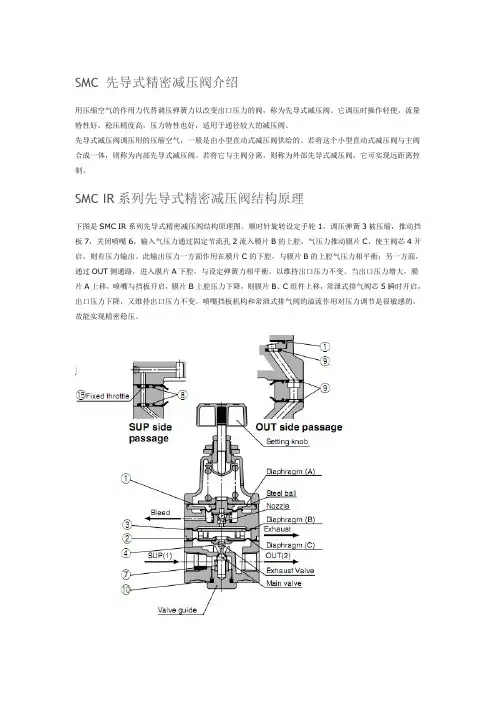
SMC IR系列先导式精密减压阀结构原理
下图是SMC IR系列先导式精密减压阀结构原理图。
顺时针旋转设定手轮1,调压弹簧3被压缩,推动挡板7,关闭喷嘴6,输入气压力通过固定节流孔2流入膜片B的上腔,气压力推动膜片C,使主阀芯4开启,则有压力输出。
此输出压力一方面作用在膜片C的下腔,与膜片B的上腔气压力相平衡;另一方面,通过OUT侧通路,进入膜片A下腔,与设定弹簧力相平衡,以维持出口压力不变。
当出口压力增大,膜片A上移,喷嘴与挡板开启,膜片B上腔压力下降,则膜片B、C组件上移,常泄式排气阀芯5瞬时开启,出口压力下降,又维持出口压力不变。
喷嘴挡板机构和常泄式排气阀的溢流作用对压力调节是很敏感的,故能实现精密稳压。
SMC IR系列先导式精密减压阀技术参数
SMC IR系列先导式精密减压阀使用注意
1)普通型减压阀,出口压力不要超过进口压力的85%;精密减压阀,出口要压力不要超过进口压力的90%。
输出压力不得超过设定压力的最大值。
2)连接配管要充分吹洗。
3)空气的流动方向按箭头方向安装,不得装反。
4)使用塑料材质的减压阀,应避免阳光直射。
阀门的三个基本参数阀门是工业生产中常见的一种用来控制流体的装置。
它的三个基本参数是:阀门口径、阀门类型和阀门材质。
本文将分别介绍这三个基本参数的作用和特点。
一、阀门口径阀门口径是指阀门内部流体通道的直径,通常使用毫米(mm)作为单位进行表示。
阀门口径的大小决定了阀门的流量和阻力。
一般来说,口径越大,阀门的流量就越大,但同时也会带来更大的压力损失。
因此,在选择阀门时需要根据具体的工况条件和流量需求来确定合适的口径。
阀门口径的选择应考虑以下几个方面:1. 流体性质:不同的流体具有不同的流动特性,有些流体对管道的阻力较大,因此需要选择较大口径的阀门来减小阻力损失。
2. 流量要求:根据流量要求选择合适的阀门口径,以保证流体的正常运行和工艺的顺利进行。
3. 管道条件:管道尺寸和阀门口径应相匹配,以确保流体的顺畅流动。
二、阀门类型阀门的类型多种多样,根据不同的工况和使用要求,可以选择不同类型的阀门。
常见的阀门类型包括截止阀、球阀、蝶阀、调节阀等。
1. 截止阀:截止阀主要用于切断或接通管道中的流体,具有良好的密封性能和较大的阻力。
常用于需要严格控制流体流量和压力的场合。
2. 球阀:球阀具有结构简单、操作方便、密封性能好等特点。
它的流体通道是一个球体,通过旋转球体来实现流体的开启和关闭。
3. 蝶阀:蝶阀的结构简单、体积小、重量轻。
它的流体通道是一个圆盘,通过旋转圆盘来控制流体的流量和压力。
4. 调节阀:调节阀主要用于调节流体的流量和压力,可以根据需要调整阀门的开度来控制流体的通畅程度。
不同类型的阀门适用于不同的工况和需求,选择合适的阀门类型可以提高生产效率和流体控制的精度。
三、阀门材质阀门的材质是指阀门主要构件的材料,它直接影响到阀门的强度、耐腐蚀性和使用寿命。
常见的阀门材质包括铸铁、不锈钢、黄铜等。
1. 铸铁:铸铁阀门具有较高的强度和耐腐蚀性,适用于一般工况下的流体控制。
2. 不锈钢:不锈钢阀门具有良好的耐腐蚀性和高温性能,适用于化工、石油、食品等工业领域。
SMC比例阀ITV使用说明书SMC比例阀ITV是一种常见的电气控制设备,被广泛应用于各种液压、气压、液压冷却系统和传动机构的控制,具有精度高、稳定性好、可靠性高等优点,广泛应用于机械、化工、冶金、石油、造船等行业。
下面,我们来详细了解一下SMC比例阀ITV使用说明书。
1. SMC比例阀ITV应用范围SMC比例阀ITV适用于中、高压液压系统及气动元件控制、温度控制及其他液压系统自动控制等领域。
2. SMC比例阀ITV的结构SMC比例阀ITV主要由壳体、底板、控制电路板、控制电磁铁、直线电位计、磁芯、机械连杆等组成。
3. SMC比例阀ITV的性能特点SMC比例阀ITV具有以下性能特点:(1)在设定控制值后,SMC比例阀ITV的输出压力或流量在一定范围内受外界环境影响较小,具有较好的稳定性。
(2)SMC比例阀ITV作为执行机构的作用,根据电信号控制电磁阀的开闭,从而调节流量或压力大小,并将调节结果反馈电路板的直线电位计上,实现自动控制。
(3)SMC比例阀ITV经过特殊设计,具有较好的液体、气体逸散性能,能长时间稳定工作。
(4)SMC比例阀ITV在工作中噪音低,效率高,运行寿命长。
4. SMC比例阀ITV的使用方法(1)SMC比例阀ITV应由专业人员安装、调试和维护,确保设备的正常运行。
(2)SMC比例阀ITV应正确接入电源和信号线,接线端子应固定牢固,并能承受电流和电压的要求。
(3)SMC比例阀ITV的漏油口应密封牢固,避免液体、气体泄漏。
(4)SMC比例阀ITV使用时应注意控制电路板和电磁铁的保护,避免电路板受潮、受热,电磁铁烧毁等事故的发生。
(5)SMC比例阀ITV的使用寿命与其实际使用环境、频率、周围温度、使用状态等因素密切相关。
因此应定期进行保养或更换配件,以确保其正常运行。
5. 总结SMC比例阀ITV作为一种常见的电气控制设备,在液压、气压等行业中具有广泛的应用。
本文从SMC比例阀ITV的应用范围、结构、性能特点、使用方法等方面进行了详细介绍。
Doc. no.XM-OMP0001-AHigh Vacuum Angle Valve / Straight ValveXMA/XYA SeriesThank you for purchasing SMC product.For appropriate operation of this product, please read this operation manual thoroughly to understand.Also, refer to the drawing, product information for structure and specification of this product, Confirm operating environment is within specifications.Keep this operation manual with care so that it can be usedat any time.Contents of this operation manual is subject to change without notice.Safety Instructions - - - - - - - - - - - - - - - - - - - - - - - - - - - - 2 1. Product Specific Precautions 1 - - - - - - - - - - - - - - - - - - - - - - - - - - - - 4(Precautions on Design, Selection, Mounting, Piping, Maintenance)2. Product Specific Precautions 2 - - - - - - - - - - - - - - - - - - - - - - - - - - - - 6(Maintenance parts)3. Specifications - - - - - - - - - - - - - - - - - - - - - - - - - - - - 74. Construction / Dimensions - - - - - - - - - - - - - - - - - - - - - - - - - - - - 85. Warranty period and guaranteed range - - - - - - - - - - - - - - - - - - - - - - - - - - - - 106.Parts replacement procedure - - - - - - - - - - - - - - - - - - - - - - - - - - - - 11Safety InstructionsThese safety instructions are intended to prevent hazardous situations and/or equipment damage. These instructions indicate the level of potential hazard with the labels of “Caution,” “Warning” or “Danger.”They are all important notes for safety and must be followed in addition to International Standards (ISO/IEC)*1), and other safety regulations.*1) ISO 4414: Pneumatic fluid power -- General rules relating to systems ISO 4413: Hydraulic fluid power -- General rules relating to systemsIEC 60204-1: Safety of machinery -- Electrical equipment of machines (Part 1: General requirements) ISO 10218-1992: Manipulating industrial robots -- SafetyCaution Caution indicates a hazard with a low level of risk which, if not avoided, could resultin minor or moderate injury.Warning Warning indicates a hazard with a medium level of risk which, if not avoided, could result in death or serious injury. DangerDanger indicates a hazard with a high level of risk which, if not avoided, will resultin death or serious injury .Safety InstructionsLimited warranty and Disclaimer/Compliance RequirementsThe product used is subject to the following “Limited warranty and Disclaimer” and “Compliance Requirements”.Read and accept them before using the product.Common Specific Precautions 1 Be sure to read before handling.●All models1. T he body material is SCS13, the bellows is SUS316L, and other metal seal material isSUS304. Standard seal material in the vacuum section is FKM that can be changed to the other materials (please refer “How to Order”). Use fluids those are compatible with using materials after confirming.2. S elect materials for the actuation pressure piping, and heat resistance for fittings that aresuitable for the applicable operating temperatures.●Models with auto switch1. T he switch section should be kept at the temperature no greater than 60 o C.●All models1. W hen controlling valve responsiveness, take note of the size and length of piping, as well asthe flow rate characteristics of the actuating solenoid valve.2. A ctuating press should be kept within the specified range. 0.4MPa to 0.5MPa is recommended.3. U se within the limits of the operating pressure range.●High temperature types1. I n the case of gases which cause a large amount of deposits, heat the valve body to preventdeposits in the valve.● All models1. I n high humidity environments, keep valves packed until the time of installation.2. I n case with switches, secure the lead wires so that they have sufficient slack, without anyunreasonable force applied to them.3. P erform piping so that excessive force is not applied to the flange sections. In case there isvibration of heavy objects or attachments, secure them so that torque is not applied directly to the flanges.4. V ibration resistance allows for normal operation of up to 30 m/s2(45 to 250Hz), butcontinuous vibration may cause a decline in durability.Arrange piping to avoid excessive vibration or impacts.● High temperature types; (Temperature specifications/H0)1. W hen a valve is to be heated, only the body section should be heated, excluding the bonnetsection.1. B efore mounting, clean the surface of the flange seal and the O-ring with ethanol, etc.2. T here is an indentation of 0.1 to 0.2mm in order to protect the flange seal surface, and itshould be handled so that the seal surface is not damaged in any way.If the fluid or reaction product (deposit) may cause the valve to become unsafe, the valve should be disassembled, cleaned and re-assembled by an operator who has sufficient knowledge and experience (e.g. a specialist).Caution1. When removing deposits from the a valve, take care not to damage any part of its parts.2. Replace the bonnet assembly and the O-ring when the end of its service life is approached. *For details regarding endurance cycles, please reference Section 5 of this Operation manual titled Period and scope of warranty . ( pages 10 )3. If damage is suspected prior to the end of the service life, perform early maintenance.4. SMC specified parts should be used for service. Refer to the Construction / Maintenance parts table.5. When removing the valve seal and external seal, take care not to damage the sealing surfaces. When installing the valve seal and external seal, be sure that the O-ring is not twisted. (Refer to Section 6 Parts Replacement Procedure (pages 11 to 13) for details.)Common Specific Precautions 2 Be sure to read before handlingOnly SMC specified parts should be used. Please refer to operation manual.The bonnet assembly should also be replaced when changing the seal material. Due to the different materials used, changing only the seal may prove inadequate.the magnet for auto switch is necessary, add “-M9//” a t the suffix of the part number. (Not available for hightemperature models)Note2) An auto switch for high temperature is available with a different part number.Note3) List the optional seal material symbol after the model number, except for the standard seal material (FKM: compound No. 1349-80).Note4) The bonnet assembly includes the valve seal.number, except for the standard seal material (FKM: compound no. 1349-80).Note2) Refer to the Construction on the page 9 for the construction numbers.Note3) Please contact SMC if you would like to change the material of the valve seal from ULTIC ARMOR to another material, or from another material to ULTIC ARMOR.Note1) Due to the different materials used, changing only the seal may prove inadequate.Note2) Barrel Perfluoro R is a registered trademark of MATSUMURA OIL Co.,Ltd.Kalrez R is a registered trademark of Dupont Co.,Ltd.Chemraz R is a registered trademark of Greene, Tweed & Co.,ULTIC ARMOR R is a registered trademark of NIPPON VALQUA INDUSTRIES, LTD.Note3) MITSUBISHI CABLE INDUSTRIES, LTD.3. SpecificationsNote1) XYA-16 is not available due to the interference of the flange shapeNote2) The conductance is “molecular flow” measured with an elbow pipe which has the same dimension with each flange.Note3) Air consumed by a reciprocating motion of a cylinder.Note4) Figures in ( ) indicates the weight of CF , conflate fittings.4-1. Construction))(保守部品))AAφGHBCCDφGHBEAφFd(K Flange )φFn (KF Flange )45°XMA Series /Angle ValveXYA Series / Straight ValveThe guaranteed period covers the period which finishes the earliest among 2 million operating cycles [with our durability test conditions], 18 months after shipping from us, and 12 months after starting the use of the product at your place or your c ustomer’s place.If the specification is not kept, or any non-conformance derived from mounting or replace of a device, an assembly, or an O-ring at your place occurs, the guarantee cannot be applied.Note)) The product durability is varied depending on the operating conditions (such as a use with large flow rate).If any failure occurs due to our fault during the guaranteed period, we will guarantee the non-conformance by delivering a substitute in the worst case. However, responsibility of any damage which is led by the product failure is not taken by us.Result of durability test (with the circuit shown on the right)Internal/ external leakage and operation were checked by opening and closing a valve in internally evacuated condition at ordinary temperature (room temperature).It was confirmed that this product satisfied the specification up to 2 million cycles.The test was performed with FKM, the standard sealing material.<Reference>The pumping direction is not limited, but if the pumping creates a flow stream, the durability of the product could be impaired.Therefore, the pumping direction shown on the right figure (bellows side pumping) is recommended. Also, the operating conditions should be checked beforehand because it affects the life.Vacuum pumpBellows side Valve sideChamberRecommended direction of exhaust6-1. PrecautionsBe sure to follow [1. Precautions 1] when disassembling the product for maintenance. Along with the precautions above, comply with the following precautions too.Warning∙If it is expected that product materials may get stuck to the product, ensure safety isassured before handling. It is recommended to wear gloves and a mask.∙Pay attention to the handling of components according to the procedure in the next itemonwards. Do not apply excessive force or impact. This will not only damage the productbut also decrease its performance and life expectancy.∙It is not possible to disassemble the bonnet assembly of this product. If the componentsand assembly are damaged, or damage is expected, exchange the bonnet assemblyitself.∙Do not disassemble the parts that are not explained in this operation manual. Theperformance and life may decrease. Also, it may cause danger.3Bolt124Bottomofdischarge gas.Mounting surface ofO ringBodyO ringO ringBodyBellows holder 1Pilot portBodyBonnet assembly234ValvesSizeX*A-251st Printing :PV 4-14-1, Sotokanda, Chiyoda-ku, Tokyo 101-0021 JAPANTel: + 81 3 5207 8249 Fax: +81 3 5298 5362URL Note: Specifications are subject to change without prior notice and any obligation on the part of the manufacturer.© 2012 SMC Corporation All Rights Reserved。
1.概述SMC系列阀门电动装置是Limitorque阀门电动装置的主体,其技术是Limitorque技术的精华和集中体现。
由SMC系列可派生出若干形式的电动装置产品。
由于被驱动控制的阀门形式不同,Limitorque电动装置亦分为两种基本形式:第一种用于控制多回转阀门,如闸阀、截止阀、隔膜阀等。
第二种用于控制部分回转阀门,如球阀、蝶阀、旋塞阀等。
在部分回转电动装置产品中通常又细分为组合式(亦称叠加式)和独立式(亦称整体式)两种结构型式。
组合式是一级多回转产品和二级减速器的组合,独立式则是将整个减速系统设置在同一个主箱体中。
实践证明,独立式部分回转电动装置是一个经济型产品,它虽然体积相对小,但组合式的很多优势它并不具备。
所以在控制性能要求较高的工况条件多首选组合式产品。
Limitorque电动装置属于高档次的产品,因而其部分回转产品多为组合式。
实际上,在多回转电动装置结构上亦有组合式的情况,最典型的是SMC系列与BA系列减速器的组合,这些会在下面详细介绍。
1.1SNC系列多回转阀门电动装置:SMC系列做为一种多回转产品,它所控制的阀门工作时阀瓣做直线运动,如最常见的楔式闸阀,平板闸阀、截止阀等等。
多回转电动装置的工作特点是:输出轴(亦称驱动空心轴)工作时做多圈回转并驱动阀杆螺母或阀杆旋转,进而带动阀瓣做上下往返运动完成阀门的启闭。
(设阀杆轴线垂至于地面)SMC系列电动装置的输出轴为上下贯通,以保证明杆阀门的阀杆通过或进入。
电动装置单行程旋转的圈数取决于阀门的口径和阀杆丝杆部分的参数。
多回转阀门可由电动装置完成行程控制关闭或转矩控制关闭,也可将两种控制形式配合使用。
SMC系列产品具有可靠的行程、转矩控制性能。
从Limitorque的直译“ 转矩限制”,我们可见输出转矩值是一个产品的重要参数。
根据输出转矩的不同又形成了产品的不同结构型式及尺寸,即不同的机座号。
SMC系列多回转电动装置共有9个机座号,它们是SMC-04~SMC~5。
SMC减压阀工作原理和型号介绍
一.SMC减压阀工作原理
1.顺时针调节手轮,调压弹簧被压缩,推动膜片组件下移,通过阀杆,打开阀芯,则入口气压力
经阀芯节流降压,压力输出;
2.出口压力气体经反馈管进入膜片下腔,在膜片产生一个向上的推力。
当此推力与调压弹簧力平
衡时,出口压力便稳定一定在值。
二.SMC减压阀特点
1.体积小,重量轻。
2.比传统的精密减压阀IR200输出流量大。
3. 比传统的精密减压阀IR200溢流流量大。
4.压力设定精确。
5.调节螺钉的齿间距由传统的0.75mm改为0.5mm。
6. 安装方便,可用托架独立安装或与现在的模块式过滤组合元件AF及AFM直接安装。
7.标准型也带面板安装。
8.先导排气口与主排气口分开。
9. 可在洁净房使用(特注产品)。
三.我们一起来看看ARJ1020F微型减压阀
特长:小型、轻量(16g) ;低开启压力0.02MPa;标准规格带逆流功能;集装板(可选项);
型号有:
ARJ310-01
ARJ310-01-1
ARJ310F-01-04
ARJ310F-01-06
ARJ310F-01BG041
10ARJ210M5BG241
ARJ1020F-M5-04
ARJ1020F-M5-041
ARJ1020F-M5-06
ARJ1020F-M5-061
ARJ210-M5
ARJ210-M5-1
ARJ210-M5-S
ARJ210-M5-X215
ARJM10-10 ARJM10-4。
SMC气控阀相关知识SMC气控阀从原理上分为三大类:1)直动式SMC气控阀:原理:通电时,电磁线圈产生电磁力把关闭件从阀座上提起,阀门打开;断电时,电磁力消失,弹簧把关闭件压在阀座上,阀门关闭。
特点:在真空、负压、零压时能正常工作,但通径一般不超过25mm。
2)分布直动式SMC气控阀:原理:它是一种直动和先导式相结合的原理,当入口与出口没有压差时,通电后,电磁力直接把先导小阀和主阀关闭件依次向上提起,阀门打开。
当入口与出口达到启动压差时,通电后,电磁力先导小阀,主阀下腔压力上升,上腔压力下降,从而利用压差把主阀向上推开;断电时,先导阀利用弹簧力或介质压力推动关闭件,向下移动,使阀门关闭。
特点:在零压差或真空、高压时亦能可动作,但功率较大,要求必须水平安装。
3)先导式SMC气控阀:原理:通电时,电磁力把先导孔打开,上腔室压力迅速下降,在关闭件周围形成上低下高的压差,流体压力推动关闭件向上移动,阀门打开;断电时,弹簧力把先导孔关闭,入口压力通过旁通孔迅速腔室在关阀件周围形成下低上高的压差,流体压力推动关闭件向下移动,关闭阀门。
特点:流体压力范围上限较高,可任意安装(需定制)但必须满足流体压差条件。
SMC气控阀是用电磁控制的工业设备,是用来控制流体的自动化基础元件,属于执行器,而气动SMC气控阀是其中的一种,是通过控制阀体的移动来档住或漏出不同的排油的孔,而进油孔是常开的,液压油就会进入不同的排油管,然后通过气动SMC气控阀的油的压力来推动油缸的活塞,这样通过控制气动SMC气控阀的电磁铁的电流就控制了整个SMC气控阀的机械运动。
SMC气控阀一般阀芯振动原因大致如下:SMC气控阀调节器输出信号不稳定。
快速的忽高忽低的变化,此时如阀门定位器灵敏度太高,则调节器输出微小的变化或飘移,就会立即转换成定位器输出信号很大。
致使阀振荡。
SMC气控阀的磨擦力太小,如调节阀的填料装得太少,或压盖没拧紧,外界输入信号有微小的变化或飘移,会立即传递给阀芯,使阀芯振动,并发出咯咯的响声。
文件No.:AR ※-OMF0022-B○ 使用产品之前请务必阅读此使用说明书。
○ 请仔细阅读安全注意事项。
○ 为了今后方便使用,请妥善保管使用说明书。
AR25K-(F,N)02~(F,N)03(B,E,G,H)(-1,N,R,Y,Z)产品名称:带逆流功能的减压阀代表型号:AR20K-(F,N)01~(F,N)02(B,E,G,H)(-1,N,R,Y,Z)AR40K-(F,N)02~(F,N)04(B,E,G,H)(-1,N,R,Y,Z)AR40K-(F,N)06(B,E,G,H)(-1,N,R,Y,Z)使 用 说 明 书AR50K-(F,N)06~(F,N)10(B,E,G)(-1,N,R,Y,Z)AR30K-(F,N)02~(F,N)03(B,E,G,H)(-1,N,R,Y,Z)AR60K-(F,N)10(B,E,G)(-1,N,R,Y,Z)目录页1、安全注意事项 1—32、用途43、规格44、型号表示方法45、故障及对策56、构造图/零件清单67、更换操作要领 7—98、分解图 10—119、外观尺寸12SMC(中国)有限公司地址:北京市经济技术开发区兴盛街甲2号 (100176)网址:2、用途 本产品用于气路中的压力控制。
内部设有逆流功能,当入口压力与出口压力相比,下降到规定量时,出口压力将向入口侧开放。
3、型号AR20K AR25K AR30K AR40K AR40K-06AR50KAR60K 管连接口径1/8、1/41/4、3/81/4、3/81/4、3/8、1/23/43/4、11使用流体保证耐压力最高使用压力注1)设定压力范围注2)压力表连接口径环境温度及使用流体温度构造质量0.26kg 0.21kg 0.29kg 0.44kg0.47kg 1.17kg 1.22kg注1) 使1次侧压力比设定压力高0.05MPa以上。
注2) 带四方形埋入式压力计时,没有压力计连接用螺钉。
4、型号表示方法型式空气1.5MPa 1.0MPa -5~60℃(无冻结)溢流型0.05~0.85MPa1/81/4设定压力+0.05MPa{只在溢流流量为0.1L/min (ANR) 时}溢流压力5.故障与对策区分现象压力不能调整1.流向错误。
smc增压阀原理
SMC增压阀是一种用来控制流体压力的装置,其工作原理基
于调整阀门开度来控制流体经过增压阀的流量,从而达到所需的压力。
SMC增压阀的主要部件包括阀体、阀芯、弹簧、调节螺钉和
密封件。
当液体流经增压阀时,流体的压力作用在阀芯上,阀芯受到压力力的作用而向上移动。
阀芯的移动导致阀门开度的变化,从而控制流体流量。
增压阀的弹簧起到平衡压力的作用,通过调节螺钉可以改变弹簧的张力,从而调整增压阀的工作压力。
当系统中的压力低于设定值时,阀芯下降,阀门开度增大,流体通过增压阀的流量增加,系统压力随之升高。
反之,当系统压力高于设定值时,阀芯上升,阀门开度减小,流体通过增压阀的流量减少,系统压力随之降低。
SMC增压阀的主要特点是具有快速响应、稳定性好、调节范
围广等优点。
其适用于液压系统、空气压缩系统和工业自动化设备等领域。
SMC电磁阀结构组成电磁阀(Electromagnetic valve)是一种利用电磁效应控制液体或气体流动的装置。
它由电磁阀芯组件、阀体组件、弹簧组件、密封件组件以及电磁铁组件等几个部分组成。
下面将详细介绍SMC电磁阀的结构组成。
1.电磁阀芯组件:电磁阀芯是电磁阀的核心部件,它由导磁片、阀座、阀体、弹簧等组成。
导磁片是铁磁材料,可受电磁线圈的激励磁化,在电磁力的作用下,与阀座接触或离开,实现控制介质通断的功能。
2.阀体组件:阀体是电磁阀的外壳,它的材料通常是铸铁、铸钢或不锈钢等。
阀体内部有阀座、阀座孔、阀门孔等构件,通过不同的控制方式,能实现不同介质的控制。
3.弹簧组件:弹簧是电磁阀的重要辅助部件,它的作用是将电磁阀芯定位或复位,保证电磁阀在工作或停止工作时能够准确地闭合或打开。
4.密封件组件:电磁阀的密封件组件主要包括密封圈、密封垫、密封圈等,用于防止介质的泄漏,保证电磁阀的正常工作。
5.电磁铁组件:电磁铁是电磁阀的动力源,通过电磁线圈产生磁场,激活导磁片,实现电磁阀的开启或关闭。
SMC电磁阀作为一种常用的气动元件,广泛应用于各个行业的自动化系统中。
它的优点是结构简单,体积小,重量轻,响应快,寿命长,可靠性高,运行稳定等。
根据需要,SMC电磁阀还可以具备电磁启动、防爆、长寿命等特殊功能。
以上是SMC电磁阀的结构组成,它们共同协作,确保电磁阀的正常工作。
在实际应用中,还需要合理选择电磁阀的型号、规格和安装位置,以满足不同的控制需求。
电磁阀的优化设计和使用条件的合理控制都能够有效提高电磁阀的工作效率,延长其使用寿命。
SMC比例阀使用SMC比例阀(Proportional Valve)是一种通过改变控制信号的大小,来调节阀的开启程度的电动阀门。
它广泛应用于工业自动化控制系统中,通过精确调节液压系统中的液压流量和压力,实现对执行器的精确控制。
1.控制信号:通过输入模拟电压或电流信号来控制比例阀的开度。
控制信号通常是由PLC或其他系统发出的,可以根据系统需要进行调整。
2.增益调节:通过调整比例阀的增益参数来控制阀的灵敏度和响应速度。
增益调节可以根据具体的应用要求进行调整,以达到最佳的控制效果。
3.电磁线圈:比例阀通过电磁线圈来控制阀门的开启程度。
当电磁线圈通电时,产生的磁场会改变阀门或阀门芯的位置,从而调节液压系统中的流量和压力。
1.精确控制:通过改变控制信号的大小,可以实现对阀门的精确控制。
这样可以确保执行器的工作效果和准确性,提高系统的稳定性和可靠性。
2.高响应速度:比例阀的开启和关闭速度可以非常快,从而实现对执行器的快速控制。
这对一些需要快速响应的应用非常重要,例如机械加工、成型和包装等。
3.灵活性:比例阀的控制信号可以通过调节电压或电流来实现,这使得它适用于各种不同类型的控制系统。
通过简单的参数调整,可以适应不同应用场景的需求。
4.可靠性:SMC比例阀采用优质的材料和精密的制造工艺,具有良好的耐磨损性和耐腐蚀性。
这使得比例阀具有较长的使用寿命和较高的可靠性。
1.工业自动化:比例阀在工业自动化领域中被广泛应用,用于控制液压系统中的流量和压力。
比例阀可以准确地控制机械运动、液压夹紧、液压顶升等操作。
2.机床加工:比例阀可以用于控制机械加工中的气动和液压系统,如切削、冲压、成型等。
通过控制流量和压力,可以实现加工过程中的精确控制和调节。
3.包装和物流:比例阀可以被应用在包装和物流系统中,用于控制输送带、装置的运动和速度。
通过精确控制流量和压力,可以确保产品的稳定输出和准确分拣。
4.冶金和矿业:比例阀在冶金和矿业领域中被广泛应用,用于控制冶金炉、矿石输送等。
S M C比例阀工作原理标准化管理处编码[BBX968T-XBB8968-NNJ668-MM9N]SMC比例阀工作原理[SMC ITV系列电气比例阀] 电气比例阀通过电信号控制气压力,可以实现气压力的连续、无级调节,能实现远程控制和程序控制,对于需要对气压力进行连续或者无级调节的场合,特别适用于电气比例阀。
对于SMC ITV系列电气比例阀有以下特点:1、灵敏度高、性能好。
保护等级为IP65.电缆方向有直线型和直角型。
2、SMC ITV0000系列为薄型(仅15mm),轻(100g)。
最多可集装至10位。
响应快(无负载时为)。
快换接头链接。
带错误显示灯(LED)。
3、SMC ITV2000/ITV3000系列为正压型,设定压力范围有三档。
在平衡状态时耗气量为0.在不加压状态下,可进行零位调整和满位调整。
在加压状态下若断电,能暂时保持输出压力不变。
有两种监控方式(模拟输出、开关输出)可供选择。
4、SMC ITV系列电气比例阀配线方法把电缆接到本体插座上应按SMC ITV系列电器使用说明书上的配线图进行配线。
配线一旦失误,阀可能损坏。
另外,DC电源应使用容量足够、电压波动小的电源。
5、SMC ITV系列电气比例阀特性曲线参见SMC ITV系列电气比例阀样本6、SMC ITV系列电气比例阀使用注意事项1)SMC ITV电气比例阀之前,应设置5μm以下过滤精度和油雾分离器,保证气源处理系统达到SMC压缩空气清净化系统第④系列的要求,向ITV比例阀提供清洁干燥的压缩空气,以便能达到ITV电气比例阀应有的各种特性。
2)SMC ITV电气比例阀之前,不得装油雾器。
3)SMC ITV电气比例阀在加压状态下切断电源,出口侧压力能暂时保持,但不能一直保持。
*SMC ITV电气比例阀其它使用注意事项,请参见SMC ITV系列电器使用说明书。
SMC ITV系列电气比例阀型号列表SMC ITV系列电气比例阀样本SMC ITV系列电气比例阀使用说明书SMC ITV电气比例阀配线图2、SMC ITV系列电气比例阀动作原理[SMC ITV系列电气比例阀动作原理图]SMC ITV2000/ITV3000系列电气比例阀动作原理图1-供气先导阀 2-膜片 3-排气阀 4-供气阀芯 5-先导室 6-压力传感器 7-排气先导阀8-控制回路[SMC ITV系列电气比例阀控制框图]SMC ITV2000/ITV3000系列电气比例阀控制框图SMC ITV2000/ITV3000系列电气比例阀动作原理图控制框图如上所示。
SMC比例阀使用SMC比例阀是一种常见的调节阀,可用于流体控制和流量调节。
它通过改变阀芯的开度来控制流体的流量和压力,具有精确的控制能力和快速的响应速度。
在工业自动化领域中,SMC比例阀广泛应用于气液控制系统、气动传动系统和流体工程领域中。
一、SMC比例阀的原理与结构1.电磁铁:通过控制电磁线圈的电流来改变阀芯的位置。
2.阀芯:阀芯是一个可移动的金属柱,通过电磁铁的作用进行上下移动,改变阀体的开口大小。
3.阀体:由进口、出口和通道组成,流体通过通道进入阀体,进而通过阀芯的开口来控制流量和压力。
二、SMC比例阀的工作原理1.控制信号输入:通过调节电磁铁的电流来控制阀芯的位置。
通常,比例阀接收的是一个电压信号(通常是0-10V或4-20mA信号),该信号可控制阀芯的位置从而改变阀体的开口大小。
2.阀芯位置调节:电磁铁的电流改变会导致阀芯的位置改变。
当电流较小时,阀芯下移,导致阀体的开口减小;当电流较大时,阀芯上移,导致阀体的开口增大。
3.流量调节:通过改变阀体的开口大小来调节流体的流量。
阀体开口增大时,流体通过阀体的面积也增大,流量也相应增加;反之,阀体开口减小,流体流量减小。
4.压力调节:SMC比例阀还可以通过改变流体通过阀体的速度来调节流体的压力。
流体通过阀体开口较小时,速度增大,压力也相应增大;流体通过阀体开口较大时,速度减小,压力也相应减小。
三、SMC比例阀的应用领域1.气液控制系统:SMC比例阀广泛应用于气液控制系统中,用于调节流体的流量、压力和温度。
它可以精确地控制气液的比例,适用于自动化生产线、机械设备等领域。
2.气动传动系统:SMC比例阀在气动传动系统中起到了重要的作用。
它通过调节气压来控制气缸或执行器的运动速度和力量,实现对气动传动过程的精确控制。
3.流体工程:SMC比例阀的流体调节能力和精度使其被广泛应用于液压系统、润滑系统、加热、冷却系统等领域中。
它可以根据不同工况对流量和压力进行即时调节,保证系统的正常运行。