
LP097X02-SLF6
- 格式:pdf
- 大小:4.91 MB
- 文档页数:26

Milliflex® PLUS PumpMXPPLUS01MXPPLUS02MXPPLUS03Security Code InstructionsIntroductionTo prevent unauthorized calibration of the weight-measurement function in theMilliflex® PLUS Pump, access to the calibration function requires the use of a security code. To maintain security, the code has been provided on this separate instruction sheet, supplied at the time of purchase.This security code instruction sheet should be secured in an appropriate location. The code should be supplied only to authorized personnel, as required.Entry of the security code will be required at the beginning of the calibration process. For further information, see the section on Calibration of the Weight-Measurement Function in the Milliflex PLUS Pump User Guide.Instructions1.After initial power-up, when the display shows Tare, use the down arrow to scrolldown to Configuration.2.Press the down arrow until the display shows Validation.3.Press OK. The display shows:WeightCalibration4.Press OK. The display shows:Enter codeor press C5.Press the START button three times, and then press OK. The display shows:Calibration DateDD MMM YY(After the first calibration, the system shows the most recent calibration date.)6.Proceed with the calibration of the weight-measurement function, as described inthe User Guide.Millipore and Milliflex are registeredtrademarks of Millipore Corporation.© 2003 Millipore Corporation.All rights reserved.P36510, Rev. A, 4/03。

® Touch Reliable• Proven, quality components.• Superior durability with modular design to ensure optimal integration and use of parts.• W-fin cooler for dependable performance in harsh environments.Savvy small and medium-sized businesses keep their energy use low and their bottom line positive. Atlas Copco GA 7-37 VSD iPM compressors ensure thoseenergy savings and much more. Supremely powerful and reliable, an Atlas Copco VSD iPM compressor is the ideal production floor companion.W-fin cooling system• W-fin cooler is dependable in harsh conditions• Axial fan enhances cooler performance4Robust oil filter/separator• Integrated bypass valve with the oil filter • Easy maintenance5Unique inverter• Unique inverter design for air compressors • Self-adjusting control in abnormal conditions7Elektronikon ® Touch controller• Integrated smart algorithms reduce system pressure and energy consumption• Warning indications, maintenance scheduling and online status visualization• Graphic display of key parameters (day, week, month) and 32 language settings6Interior Permanent Magnet (iPM) motor• Very high efficiency: equals IE4 standards • Compact, customized design for optimal cooling by oil• IP56 protection for GA 7-22 VSD iPM; IP66 for GA 30-37 VSD iPM.• No cooling air flow required • Oil-lubricated motor1Element• Made by Atlas Copco • Robust and silent • High efficiency2Direct drive• No gears or belts• Compact: footprint down 30%3412367Only the pioneer of Variable Speed Drive compressors can give you real VSD energy savings.Thanks to its innovative drivetrain and high-tech Neos inverter, an Atlas Copco GA 45-90 VSD iPM gives you energy savings of up to 35% for a more sustainable production and significantly lower operational costs.Classic cooling system• Separate oil/air cooler• W-fin cooler is dependable in harsh conditions • Axial fan enhances cooler performance • Lower temperature ensures efficient operation4Robust oil filter/separator• Integrated bypass valve with the oil filter• Optimized spin-on design • Easy access and maintenance5Innovative Neos Inverter• Atlas Copco’s in-house designed inverter, now also controls iPM motors• IP5x protection• Robust aluminum enclosure for trouble-free operation in the harshest conditions• Fewer components: compact, simple and user-friendly7Elektronikon ® Touch controller• High-tech controller with warning indications,compressor shutdown and maintenance scheduling • Standard SMART LINK remote monitoring to maximize air system performance and energy savings • Optional multiple compressor control (2, 4 or 6 compressors)6Interior Permanent Magnet (iPM) motor• Very high efficiency: equals IE4 standards • Compact, customized design for optimal oil cooling• IP66, insulation class F, B rise • No cooling air flow required • Oil-lubricated motor1Element• Made by Atlas Copco • Robust and silent• High efficiency2Premium drive type• Reliable direct drive for GA 45-75 VSD iPM• Newly developed gear drive for GA 90 VSD iPM ensures easy maintenance • Oil-cooled, pressure-tight312345674LINK brings real-time monitoring of yourcompressor’s operational parameters to your computer • Performance data and insights identify opportunities • Maintenance and service alerts.• Online resource center with manuals, documentation and technical information.Elektronikon ® Touch• Ease of use: 4.3-inch high-definition color display with clear pictograms and service indicator.• Reliable: user-friendly, multilingual user interface and durable keyboard.• Flexible: four different week schedules for 10 consecutive weeks.• Internet-based compressor visualization with a simpleHLWTechnical specifications GA 7-90 VSD iPMInlet filterOil stop valve Screw element Inlet valveAir/oil vessel separator Thermostatic bypass valve Oil filterSafety valveMinimum pressure valve Solenoid valve After cooler Fan Oil cooler12345678910111213Wet compressed air Intake air Air/oil mixture Dry compressed air Oil* Unit performance measured according to ISO 1217 ed. 4 2009, annex E, latest edition.** Mean noise level measured at a distance of 1 m according to ISO 2151: 2004 using ISO 9614/2 (sound intensity method); tolerance 3 dB(A).Reference conditions:- Absolute inlet pressure 1 bar/14.5 psi.- Intake air temperature 20°C/68°F.FAD is measured at the following effective working pressures: - 4 bar(e)- 7 bar(e)- 10 bar(e)- 12.5 bar(e)Maximum working pressure: 13 bar(e)/188 psigFlow chart GA 7-37 VSD iPMInlet filterSpring inlet valve Screw element Air/oil vessel separator Oil separatorOil filter MotorOil cooler After cooler FanSolenoid valve12345678910111213Wet compressed air Intake air Air/oil mixture Dry compressed air Oil2935 0816 48 ©2022, A t l a s C o p c o . A l l r i g h t s r e s e r v e d . D e s i g n s a n d s p e c i fi c a t i o n s a r e s u b j e c t t o c h a n g e w i t h o u t n o t i c e o r o b l i g a t i R e a d a l l s a f e t y i n s t r u c t i o n s i n t h e m a n u a l b e f o r e u s a g e .。
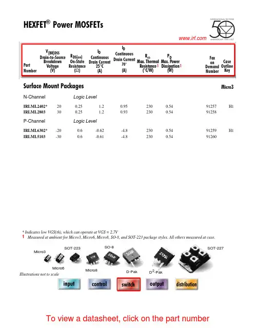
I DContinuous Drain Current(A)70°Micro3Surface Mount PackagesV (BR)DSSDrain-to-Source Breakdown Voltage (V)R DS(on)On-State Resistance ()ΩI D Continuous Drain Current 25°C(A)R ΘMax.Thermal Resistance (°C/W)1FaxonDemand Number Case Outline KeyPartNumberPD Max.PowerDissipation (W)N-ChannelLogic LevelIRLML2402*912570.54200.25 1.20.95230H1IRLML2803912580.54300.251.20.93230P-ChannelLogic LevelIRLML6302*912590.54-200.6-0.62-4.8230H1IRLML5103912600.54-300.6-0.61-4.8230* Indicates low VGS(th), which can operate at VGS = 2.7VMeasured at ambient for Micro3, Micro6, Micro8, SO-8, and SOT-223 package styles. All others measured at case.1Micro3SO-8D-PakD -PakSOT-227Micro6SOT-223Micro82 Illustrations not to scaleI DContinuous Drain Current(A)70°Micro6Surface Mount PackagesV (BR)DSSDrain-to-Source Breakdown Voltage (V)R DS(on)On-State Resistance ()ΩI D Continuous Drain Current 25°C(A)R ΘMax.Thermal Resistance (°C/W)1FaxonDemand Number Case Outline KeyPartNumberPD Max.PowerDissipation (W)N-ChannelLogic LevelIRLMS1902915401.7200.10 3.2 2.675H2IRLMS1503915081.7300.103.22.675P-ChannelLogic LevelIRLMS6702*914141.7-200.20-2.3-1.975H2IRLMS5703914131.7-300.20-2.3-1.975* Indicates low VGS(th), which can operate at VGS = 2.7VMeasured at ambient for Micro3, Micro6, Micro8, SO-8, and SOT-223 package styles. All others measured at case.1Micro3SO-8D-PakD -PakSOT-227Micro6SOT-223Micro82 Illustrations not to scaleI DContinuous Drain Current(A)70°Micro8Surface Mount PackagesV (BR)DSSDrain-to-Source Breakdown Voltage (V)R DS(on)On-State Resistance ()ΩI D Continuous Drain Current 25°C(A)R ΘMax.Thermal Resistance (°C/W)1FaxonDemand Number Case Outline KeyPart NumberP D Max.PowerDissipation (W)N-Channel Logic LevelIRF7601* 912611.820 0.035 5.7 4.6 70 H3IRF7603 912621.830 0.035 5.6 4.5 70Dual N-Channel Logic LevelIRF7501* 912651.220 0.135 2.4 1.9 100 H3IRF7503 912661.2530 0.135 2.4 1.9 100P-Channel Logic LevelIRF7604* 912631.8-20 0.09 -3.6 -2.9 70 H3IRF7606 912641.8-30 0.09 -3.6 -2.9 70Dual P-Channel Logic LevelIRF7504* 912671.25-20 0.27 -1.7 -1.4 100 H3IRF7506 912681.25-30 0.27 -1.7 -1.4 100Dual N- and P-Channel Logic LevelIRF7507* 912691.2520 0.1352.4 1.9 100 H3-20 0.27 -1.7 -1.4IRF7509 912701.2530 0.135 2.4 1.9 100-30 0.27 -1.7 -1.4* Indicates low VGS(th), which can operate at VGS = 2.7VMeasured at ambient for Micro3, Micro6, Micro8, SO-8, and SOT-223 package styles. All others measured at case.1Micro3SO-8D-Pak D -PakSOT-227Micro6SOT-223Micro8 2 Illustrations not to scaleI DContinuous Drain Current(A)70°SO-8Surface Mount PackagesV (BR)DSSDrain-to-Source Breakdown Voltage (V)R DS(on)On-State Resistance ()ΩI D Continuous Drain Current 25°C(A)R ΘMax.Thermal Resistance (°C/W)1FaxonDemand Number Case Outline KeyPart Number P D Max.PowerDissipation (W)N-ChannelIRF7413913302.5300.011139.250H4IRF7413A 916132.5300.0135128.450IRF9410915622.5300.0375.850Dual N-ChannelIRF7311914352.0200.029 6.6 5.362.5H4IRF7313914802.0300.029 6.5 5.262.5IRF7333917002.0300.10 3.5 2.862.5917002.0300.050 4.9 3.962.5IRF9956915592.0300.103.52.862.5Dual P-ChannelIRF7314914352.0-200.058-5.3-4.362.5H4IRF7316915052.0-300.058-4.9-3.962.5IRF9953915602.0-300.25-2.3-1.862.5* Indicates low VGS(th), which can operate at VGS = 2.7VMeasured at ambient for Micro3, Micro6, Micro8, SO-8, and SOT-223 package styles. All others measured at case.1Micro3SO-8D-PakD -PakSOT-227Micro6SOT-223Micro82 Illustrations not to scaleI DContinuous Drain Current(A)70°SO-8Surface Mount PackagesV (BR)DSSDrain-to-Source Breakdown Voltage (V)R DS(on)On-State Resistance ()ΩI D Continuous Drain Current 25°C(A)RΘMax.ThermalResistance(°C/W)1FaxonDemand Number Case Outline KeyPart NumberP D Max.PowerDissipation (W)Dual N- and P-ChannelIRF7317 915682.020 0.029 6.6 5.3 62.5 H42.0-20 0.058 -5.3 -4.3 62.5IRF9952 915622.030 0.103.5 2.8 62.5915622.0-30 0.25 -2.3 -1.8 62.5IRF7319 916062.030 0.029 6.5 5.2 62.52.0-30 0.058 -4.9 -3.9 62.5* Indicates low VGS(th), which can operate at VGS = 2.7VMeasured at ambient for Micro3, Micro6, Micro8, SO-8, and SOT-223 package styles. All others measured at case.1Micro3SO-8D-Pak D -PakSOT-227Micro6SOT-223Micro8 2 Illustrations not to scaleI DContinuous Drain Current(A)70°SO-8Surface Mount PackagesV (BR)DSSDrain-to-Source Breakdown Voltage (V)R DS(on)On-State Resistance ()ΩI D Continuous Drain Current 25°C(A)R ΘMax.Thermal Resistance (°C/W)1FaxonDemand Number Case Outline KeyPart Number P D Max.PowerDissipation (W)N-ChannelLogic LevelIRF7401912442.5200.0228.77.050H4IRF7201911002.5300.0307.0 5.650IRF7403912452.5300.0228.55.450Dual N-ChannelLogic LevelIRF7101908712.0200.10 3.5 2.362.5H4IRF7301912382.0200.050 5.2 4.162.5IRF7303912392.0300.050 4.9 3.962.5IRF7103910952.0500.1303.02.362.5P-ChannelLogic LevelIRF7204911032.5-200.060-5.3-4.250H4IRF7404912462.5-200.040-6.7-5.450IRF7205911042.5-300.070-4.6-3.750IRF7406912472.5-300.045-5.8-3.750IRF7416913562.5-300.02-10-7.150* Indicates low VGS(th), which can operate at VGS = 2.7VMeasured at ambient for Micro3, Micro6, Micro8, SO-8, and SOT-223 package styles. All others measured at case.1Micro3SO-8D-PakD -PakSOT-227Micro6SOT-223Micro82 Illustrations not to scaleI DContinuous Drain Current(A)70°SO-8Surface Mount PackagesV (BR)DSSDrain-to-Source Breakdown Voltage (V)R DS(on)On-State Resistance ()ΩI D Continuous Drain Current 25°C(A)R ΘMax.Thermal Resistance (°C/W)1FaxonDemand Number Case Outline KeyPart Number P D Max.PowerDissipation (W)Dual P-ChannelLogic LevelIRF7104910962.0-200.250-2.3-1.862.5H4IRF7304912402.0-200.090-4.3-3.462.5IRF7306912412.0-300.10-3.6-2.962.5Dual N- and P-Channe Logic LevelIRF7307912421.4200.050 4.3 3.490H4-200.090-3.6-2.9IRF7105910972.0250.1093.5 2.862.52-250.25-2.3-1.862IRF7309912432.0300.050 4.9 3.962.5-300.10-3.6-2.9* Indicates low VGS(th), which can operate at VGS = 2.7VMeasured at ambient for Micro3, Micro6, Micro8, SO-8, and SOT-223 package styles. All others measured at case.1Micro3SO-8D-PakD -PakSOT-227Micro6SOT-223Micro82 Illustrations not to scaleI DContinuous Drain Current(A)70°SOT-223Surface Mount PackagesV (BR)DSSDrain-to-Source Breakdown Voltage (V)R DS(on)On-State Resistance ()ΩI D Continuous Drain Current 25°C(A)R ΘMax.Thermal Resistance (°C/W)1FaxonDemand Number Case Outline KeyPart Number P D Max.PowerDissipation (W)N-ChannelIRFL4105913812.1550.045 3.7 3.060H6IRFL110908612.01000.54 1.50.9660IRFL4310913682.11000.20 1.6 1.360IRFL21090868 2.02001.50.960.660IRFL214908622.02502.00.790.560P-ChannelIRFL9110908642.0-1001.2-1.1-0.6960H6N-ChannelLogic LevelIRLL3303913792.1300.031 4.6 3.760H6IRLL014N 914992.1550.14 2.0 1.660IRLL2705913802.1550.043.83.060* Indicates low VGS(th), which can operate at VGS = 2.7VMeasured at ambient for Micro3, Micro6, Micro8, SO-8, and SOT-223 package styles. All others measured at case.1Micro3SO-8D-PakD -PakSOT-227Micro6SOT-223Micro82 Illustrations not to scaleI DContinuous Drain Current(A)100°D-PakSurface Mount PackagesV (BR)DSSDrain-to-Source Breakdown Voltage (V)R DS(on)On-State Resistance ()ΩI D Continuous Drain Current 25°C(A)R ΘMax.Thermal Resistance (°C/W)1FaxonDemand Number Case Outline KeyPart Number P D Max.PowerDissipation (W)N-ChannelIRFR33039164257300.0313321 2.2H7IRFR024N9133638550.0751610 3.3IRFR41059130248550.0452516 2.7IRFR12059131869550.0273723 1.8IRFR11090524251000.54 4.3 2.75IRFR120N 91365391000.219.1 5.8 3.2IRFR391091364521000.11159.5 2.4IRFR2109052625200 1.5 2.6 1.75IRFR22090525422000.8 4.833IRFR21490703252502 2.2 1.45IRFR2249060042250 1.1 3.8 2.43IRFR3109059725400 3.6 1.7 1.15IRFR3209059842400 1.8 3.123IRFR42090599425003 2.4 1.53IRFRC2090637426004.421.33* Indicates low VGS(th), which can operate at VGS = 2.7VMeasured at ambient for Micro3, Micro6, Micro8, SO-8, and SOT-223 package styles. All others measured at case.1Micro3SO-8D-PakD -PakSOT-227Micro6SOT-223Micro82 Illustrations not to scaleI DContinuous Drain Current(A)100°D-PakSurface Mount PackagesV (BR)DSSDrain-to-Source Breakdown Voltage (V)R DS(on)On-State Resistance ()ΩI D Continuous Drain Current 25°C(A)R ΘMax.Thermal Resistance (°C/W)1FaxonDemand Number Case Outline KeyPart Number P D Max.PowerDissipation (W)P-ChannelIRFR55059161057-550.11-18-11 2.2H7IRFR53059140289-550.065-28-18 1.4IRFR90149065425-600.5-5.1-3.25IRFR90249065542-600.28-8.8-5.63IRFR91109051925-100 1.2-3.1-25IRFR91209052042-1000.6-5.6-3.63IRFR9120N 9150739-1000.48-6.5-4.1 3.2IRFR92109052125-2003-1.9-1.25IRFR92209052242-200 1.5-3.6-2.33IRFR92149165850-250 3.0-2.7-1.7 2.5IRFR93109166350-4007.0-1.8-1.12.5* Indicates low VGS(th), which can operate at VGS = 2.7VMeasured at ambient for Micro3, Micro6, Micro8, SO-8, and SOT-223 package styles. All others measured at case.1Micro3SO-8D-PakD -PakSOT-227Micro6SOT-223Micro82 Illustrations not to scaleI DContinuous Drain Current(A)100°D-PakSurface Mount PackagesV (BR)DSSDrain-to-Source Breakdown Voltage (V)R DS(on)On-State Resistance ()ΩI D Continuous Drain Current 25°C(A)R ΘMax.Thermal Resistance (°C/W)1FaxonDemand Number Case Outline KeyPart Number P D Max.PowerDissipation (W)N-ChannelLogic LevelIRLR27039133538300.0452214 3.3H7IRLR33039131657300.0313321 2.2IRLR31039133369300.0194629 1.8IRLR024N 9136338550.0651711 3.3IRLR27059131746550.042415 2.7IRLR29059133469550.0273623 1.8IRLR120N 91541391000.18511 6.9 3.2IRLR341091607521000.10159.52.4* Indicates low VGS(th), which can operate at VGS = 2.7VMeasured at ambient for Micro3, Micro6, Micro8, SO-8, and SOT-223 package styles. All others measured at case.1Micro3SO-8D-PakD -PakSOT-227Micro6SOT-223Micro82 Illustrations not to scaleI DContinuous Drain Current(A)100°D 2PakSurface Mount PackagesV (BR)DSSDrain-to-Source Breakdown Voltage (V)R DS(on)On-State Resistance ()ΩI D Continuous Drain Current 25°C(A)R ΘMax.Thermal Resistance (°C/W)1FaxonDemand Number Case Outline KeyPart NumberP D Max.PowerDissipation (W)N-ChannelIRFZ24NS 913554555 0.07 17 12 3.3 H10IRFZ34NS 913116855 0.04 29 20 2.2IRFZ44NS 9131511055 0.022 49 35 1.4IRFZ46NS 9130512055 0.020 53 37 1.3IRFZ48NS 9140814055 0.016 64 45 1.1IRF1010NS 913723.855 0.011 84 60 40IRF3205S 9130420055 0.008 110 80 0.75IRFZ44ES 9171411060 0.023 48 34 1.4IRF1010ES 9172017060 0.012 83 59 0.90IRF2807S 9151815075 0.013 71 50 1.0IRF520NS 9134047100 0.2 9.5 6.7 3.2IRF530NS 9135263100 0.11 15 11 2.4IRF540NS 91342110100 0.052 27 19 1.6IRF1310NS 91514120100 0.036 36 25 1.3IRF3710S 91310150100 0.028 46 33 1.0IRF3315S 9161794150 0.082 21 15 1.6IRF3415S 91509150150 0.042 37 26 1.0IRFBC20S 9.101450600 4.4 2.2 1.4 2.5IRFBC30S 9101574600 2.2 3.6 2.3 1.7IRFBC40S 91016130600 1.2 6.2 3.9 1.0* Indicates low VGS(th), which can operate at VGS = 2.7VMeasured at ambient for Micro3, Micro6, Micro8, SO-8, and SOT-223 package styles. All others measured at case.1Micro3SO-8D-Pak D -PakSOT-227Micro6SOT-223Micro8 2 Illustrations not to scaleI DContinuous Drain Current(A)100°D 2PakSurface Mount PackagesV (BR)DSSDrain-to-Source Breakdown Voltage (V)R DS(on)On-State Resistance ()ΩI D Continuous Drain Current 25°C(A)R ΘMax.Thermal Resistance (°C/W)1FaxonDemandNumberCase Outline KeyPart NumberP D Max.PowerDissipation (W)IRFBF20S 9166554900 8.0 1.7 1.1 2.3 H10P-ChannelIRF5305S 91386110-55 0.06 -31 -22 1.4 H10IRF4905S 914783.8-55 0.02 -74 -52 40IRF9520NS 9152247-100 0.48 -6.7 -4.8 3.2IRF9530NS 9152375-100 0.20 -14 -9.9 2.0IRF9540NS 9148394-100 0.117 -19 -13 1.6IRF5210S 91405150-100 0.06 -35 -25 1.0* Indicates low VGS(th), which can operate at VGS = 2.7VMeasured at ambient for Micro3, Micro6, Micro8, SO-8, and SOT-223 package styles. All others measured at case.1Micro3SO-8D-Pak D -PakSOT-227Micro6SOT-223Micro8 2 Illustrations not to scaleI DContinuous Drain Current(A)100°D 2PakSurface Mount PackagesV (BR)DSSDrain-to-Source Breakdown Voltage (V)R DS(on)On-State Resistance ()ΩI D Continuous Drain Current 25°C(A)R ΘMax.Thermal Resistance (°C/W)1FaxonDemand Number Case Outline KeyPart NumberP D Max.PowerDissipation (W)N-Channel Logic LevelIRL3302S 916925720 0.020 39 25 2.2 H10IRL3202S916756920 0.016 48 30 1.8IRL3102S 916918920 0.013 61 39 1.4IRL3402S 9169311020 0.01 85 54 1.1IRL3502S 9167614020 0.007 110 67 0.89IRL2703S 913604530 0.04 24 17 3.3IRL3303S 913236830 0.026 38 27 2.2IRL3103S 9133811030 0.014 64 45 1.4IRL2203NS 9136717030 0.007 116 82 0.90IRL3803S 9131920030 0.006 140 98 0.75IRLZ24NS 913584555 0.06 18 13 3.3IRLZ34NS 913086855 0.035 30 21 2.2IRLZ44NS 9134711055 0.022 47 33 1.4IRL3705NS 9150217055 0.01 89 63 0.90IRL2505S 9132620055 0.008 104 74 0.75IRLZ44S 9090615060 0.028 50 36 1.0IRL530NS 9134963100 0.1 15 11 2.4IRL2910S 91376150100 0.026 48 34 1.0* Indicates low VGS(th), which can operate at VGS = 2.7VMeasured at ambient for Micro3, Micro6, Micro8, SO-8, and SOT-223 package styles. All others measured at case.1Micro3SO-8D-Pak D -PakSOT-227Micro6SOT-223Micro8 2 Illustrations not to scaleI DContinuous Drain Current(A)100°SOT-227Surface Mount PackagesV (BR)DSSDrain-to-Source Breakdown Voltage (V)R DS(on)On-State Resistance ()ΩI D Continuous DrainCurrent 25°C(A)RΘMax.Thermal Resistance (°C/W)1FaxonDemand Number Case Outline KeyPart Number P D Max.PowerDissipation (W)N-ChannelFully Isolated Low ChargeFA38SA50LC 916155005000.1338240.25H21FA57SA50LC916506255000.0857360.20* Indicates low VGS(th), which can operate at VGS = 2.7VMeasured at ambient for Micro3, Micro6, Micro8, SO-8, and SOT-223 package styles. All others measured at case.1Micro3SO-8D-PakD -PakSOT-227Micro6SOT-223Micro82 Illustrations not to scaleI DContinuous Drain Current(A)100°I-PakThrough-Hole PackagesV (BR)DSSDrain-to-Source Breakdown Voltage (V)R DS(on)On-State Resistance ()ΩI D Continuous Drain Current 25°C(A)R ΘMax.Thermal Resistance (°C/W)1FaxonDemand Number Case Outline KeyPart Number P D Max.PowerDissipation (W)N-ChannelIRFU33039164257300.0313321 2.2H8IRFU024N 9133638550.0751610 3.3IRFU41059130248550.0452519 2.7IRFU12059131869550.0273723 1.8IRFU11090524251000.54 4.3 2.7 5.0IRFU120N 91365391000.219.1 5.8 3.2IRFU391091364521000.11159.5 2.4IRFU2109052625200 1.5 2.6 1.7 5.0IRFU22090525422000.80 4.8 3.0 3.0IRFU2149070325250 2.0 2.2 1.4 5.0IRFU2249060042250 1.1 3.8 2.4 3.0IRFU3109059725400 3.6 1.7 1.1 5.0IRFU3209059842400 1.8 3.1 2.0 3.0IRFU4209059942500 3.0 2.4 1.5 3.0IRFUC2090637426004.42.01.33.0I-PakTO-220 FullPakTO-262TO-247HEXDIPTO-220AB Illustrations not to scale** Not ratedI DContinuous Drain Current(A)100°I-PakThrough-Hole PackagesV (BR)DSSDrain-to-Source Breakdown Voltage (V)R DS(on)On-State Resistance ()ΩI D Continuous Drain Current 25°C(A)R ΘMax.Thermal Resistance (°C/W)1FaxonDemand Number Case Outline KeyPart Number P D Max.PowerDissipation (W)P-ChannelIRFU55059161057-550.11-18-11 2.2H8IRFU53059140289-550.065-28-18 1.4IRFU90149065425-600.50-5.1-3.2 5.0IRFU90249065542-600.28-8.8-5.6 3.0IRFU91109051925-100 1.2-3.1-2.0 5.0IRFU91209052042-1000.60-5.6-3.6 3.0IRFU9120N 9150739-1000.48-6.5-4.1 3.2IRFU92109052125-200 3.0-1.9-1.2 5.0IRFU92209052242-200 1.5-3.6-2.3 3.0IRFU92149165850-2503.0-2.7-1.7 2.5IRFU93109166350-4007.0-1.8-1.12.5N-ChannelLogic LevelIRLU27039133538300.0452214 3.3H8IRLU33039131657300.0313321 2.2IRLU31039133369300.0194629 1.8IRLU024N 9136338550.0651711 3.3IRLU27059131746550.04241715IRLU29059133469550.0273623 1.8IRLU120N 91541391000.18511 6.9 3.2IRLU341091607521000.10159.52.4I-PakTO-220 FullPakTO-262TO-247HEXDIPTO-220AB Illustrations not to scale** Not ratedI DContinuous Drain Current(A)100°HEXDIPThrough-Hole PackagesV (BR)DSSDrain-to-Source Breakdown Voltage (V)R DS(on)On-State Resistance ()ΩI D Continuous Drain Current 25°C(A)R ΘMax.Thermal Resistance (°C/W)1FaxonDemand Number Case Outline KeyPart Number P D Max.PowerDissipation (W)N-ChannelIRFD014907001.3600.2 1.7 1.2120H9IRFD024906991.3600.1 2.5 1.8120IRFD110903281.31000.54 1.00.71120IRFD120903851.31000.27 1.30.94120IRFD210903861.3200 1.50.60.38120IRFD220904171.32000.80.80.50120IRFD214912711.3250 2.00.570.32120IRFD224912721.3250 1.10.760.43120IRFD310912251.3400 3.60.420.23120IRFD320912261.3400 1.80.600.33120IRFD420912271.3500 3.00.460.26120IRFDC20912281.36004.40.320.21120I-PakTO-220 FullPakTO-262TO-247HEXDIPTO-220AB Illustrations not to scale** Not ratedI D Continuous Drain Current (A)100°TO-220Qg TotalGate Charge(nC)Through-Hole PackagesV (BR)DSSDrain-to-Source Breakdown Voltage (V)R DS(on)On-State Resistance ()ΩI D Continuous Drain Current 25°C (A)R ΘMax.Thermal Resistance(°C/W)1Faxon Demand Number Case OutlineKeyPart Number P D Max.Power Dissipation (W)N-ChannelLow ChargeIRF737LC91314743000.75 6.1** 1.7 3.9H11IRF740LC 910681254000.5510** 1.039IRF840LC 910691255000.858.0** 1.039IRFBC40LC910701256001.26.2**1.039I-PakTO-220 FullPakTO-262TO-247HEXDIPTO-220AB Illustrations not to scale** Not ratedI DContinuous Drain Current(A)100°TO-220ABThrough-Hole PackagesV (BR)DSSDrain-to-Source Breakdown Voltage (V)R DS(on)On-State Resistance ()ΩI D Continuous Drain Current 25°C(A)R ΘMax.Thermal Resistance (°C/W)1FaxonDemand Number Case Outline KeyPart Number P D Max.PowerDissipation (W)N-ChannelIRFZ24N 9135445550.071712 3.3H12IRFZ34N9127656550.042618 2.7IRFZ44N 9130383550.0244129 1.8IRFZ46N 9127788550.024633 1.7IRFZ48N 9140694550.0165337 1.6IRF1010N 91278130550.0127251 1.2IRF320591279150550.0089869 1.0IRFZ34E 9167268600.0422820 2.2IRFZ44E 91671110600.0234834 1.4IRF1010E 91670170600.01281570.90IRF280791517150750.0137150 1.0IRF520N 91339471000.209.5 6.79.5IRF530N 91351601000.111511 2.4IRF540N 91341941000.0522719 1.6IRF1310N 916111201000.0363625 1.3IRF3710913091501000.0284633 1.0IRF331591623941500.0822115 1.6IRF3415914771501500.0423726 1.0IRFBC209062350600 4.4 2.2 1.4 2.5IRFBC309048274600 2.2 3.6 2.3 1.7IRFBC4090506125600 1.2 6.2 3.9 1.0IRFBE2090610548006.51.81.22.3I-PakTO-220 FullPakTO-262TO-247HEXDIPTO-220AB Illustrations not to scale** Not ratedI DContinuous Drain Current(A)100°TO-220ABThrough-Hole PackagesV (BR)DSSDrain-to-Source Breakdown Voltage (V)R DS(on)On-State Resistance ()ΩI D Continuous Drain Current 25°C(A)R ΘMax.Thermal Resistance (°C/W)1FaxonDemand Number Case Outline KeyPart Number P D Max.PowerDissipation (W)IRFBE3090613125800 3.0 4.1 2.6 2.0H12IRFBF3090616125900 3.7 3.6 2.3 1.0IRFBG209060454100011 1.40.86 2.3IRFBG309062012510005.03.12.01.0P-ChannelIRF9Z24N 9148445-550.175-12-8.53.3H12IRF9Z34N 9148556-550.10-17-12 2.7IRF530591385110-550.06-31-22 1.4IRF490591280150-550.02-64-45 1.0IRF9530N 9148275-1000.20-13-9.2 2.0IRF9540N 9143794-1000.117-19-13 1.6IRF521091434150-1000.06-35-25 1.0IRF62159147983-1500.29-11-7.81.8I-PakTO-220 FullPakTO-262TO-247HEXDIPTO-220AB Illustrations not to scale** Not ratedI DContinuous Drain Current(A)100°TO-220ABThrough-Hole PackagesV (BR)DSSDrain-to-Source Breakdown Voltage (V)R DS(on)On-State Resistance ()ΩI D Continuous Drain Current 25°C(A)R ΘMax.Thermal Resistance (°C/W)1FaxonDemand Number Case Outline KeyPart NumberP D Max.PowerDissipation (W)N-Channel Logic LevelIRL3302 916965720 0.020 39 25 2.2 H12IRL3202 916956920 0.016 48 30 1.8IRL3102 916948920 0.013 61 39 1.4IRL3402 9169711020 0.01 85 54 1.1IRL3502 9169814020 0.007 110 67 0.89IRL2703 913594530 0.04 24 17 3.3IRL3303 913225630 0.026 34 24 2.7IRL3103 913378330 0.014 56 40 1.8IRL2203N 9136613030 0.007 100 71 1.230 0.007 61 43 3.2IRL3803 9130115030 0.006 120 83 1.0IRLZ24N 913574555 0.06 18 13 3.3IRLZ34N 913075655 0.035 27 19 2.7IRLZ44N 913468355 0.022 41 29 1.8IRL3705N 9137013055 0.01 77 54 1.2IRL2505 9132520055 0.008 104 74 0.75IRL520N 9149447100 0.18 10 7.1 3.2IRL530N 9134863100 0.10 15 11 2.4IRL540N 9149594100 0.044 30 21 1.6IRL2910 91375150100 0.026 48 34 1.0I-PakTO-220 FullPakTO-262TO-247HEXDIPTO-220AB Illustrations not to scale** Not ratedI D Continuous Drain Current (A)100°TO-220 FullPak (Fully Isolated)Qg TotalGate Charge(nC)Through-Hole PackagesV (BR)DSSDrain-to-Source Breakdown Voltage (V)R DS(on)On-State Resistance ()ΩI D Continuous DrainCurrent 25°C(A)R ΘMax.Thermal Resistance (°C/W)1Fax on Demand Number Case OutlineKeyPart Number P D Max.Power Dissipation (W)N-ChannelLow ChargeIRFI740GLC91209404000.55 6.0** 3.139H13IRFI840GLC 91208405000.85 4.8** 3.139IRFIBC40GLC91211406001.24.0**3.139I-PakTO-220 FullPakTO-262TO-247HEXDIPTO-220AB Illustrations not to scale** Not ratedI DContinuous Drain Current(A)100°TO-220 FullPak (Fully Isolated)Through-Hole PackagesV (BR)DSSDrain-to-Source Breakdown Voltage (V)R DS(on)On-State Resistance ()ΩI D Continuous Drain Current 25°C(A)R ΘMax.Thermal Resistance (°C/W)1FaxonDemand Number Case Outline KeyPart Number P D Max.PowerDissipation (W)N-ChannelIRFIZ24N 9150126550.07139.2 5.8H14IRFIZ34N9148931550.041913 4.8IRFIZ44N 9140338550.02428200.024IRFIZ46N 9130640550.023122 3.8IRFIZ48N 9140742550.0163625 3.6IRFI1010N 9137347550.0124431 3.2IRFI32059137448550.0085640 3.1IRFIZ24E 9167329600.071149.6 5.2IRFIZ34E 9167437600.0422115 4.1IRFI510G 90829271000.54 4.5 3.2 5.5IRFI520N 91362271000.207.2 5.1 5.5IRFI530N 91353331000.11117.8 4.5IRFI540N 91361421000.0521813 3.6IRFI1310N 91611451000.0362216 3.3IRFI371091387481000.0252820 3.1IRFI620G 90832302000.8 4.1 2.6 4.1IRFI630G 90652322000.4 5.9 3.7 3.6IRFI640G 90649402000.189.8 6.2 3.1IRFI614G 9083123250 2.0 2.1 1.3 5.5IRFI624G 9083330250 1.1 3.4 2.2 4.1IRFI634G 90738322500.45 5.6 3.5 3.6IRFI644G 90739402500.287.953.1I-PakTO-220 FullPakTO-262TO-247HEXDIPTO-220AB Illustrations not to scale** Not ratedI DContinuous Drain Current(A)100°TO-220 FullPak (Fully Isolated)Through-Hole PackagesV (BR)DSSDrain-to-Source Breakdown Voltage (V)R DS(on)On-State Resistance ()ΩI D Continuous Drain Current 25°C(A)R ΘMax.Thermal Resistance (°C/W)1FaxonDemand Number Case Outline KeyPart Number P D Max.PowerDissipation (W)IRFI720G 9083430400 1.8 2.6 1.7 4.1H14IRFI730G 9065032400 1.0 3.7 2.3 3.6IRFI740G 90651404000.55 5.4 3.4 3.1IRFI734G 9100135450 1.2 3.4 2.1 3.6IRFI744G 91002404500.63 4.9 3.1 3.1IRFI820G 9064130500 3.0 2.1 1.3 4.1IRFI830G 9064632500 1.5 3.12 3.6IRFI840G 90642405000.85 4.6 2.9 3.1IRFIBC20G 90850306004.41.71.1 4.1IRFIBC30G 90851356002.2 2.5 1.63.6IRFIBC40G 9085240600 1.2 3.5 2.2 3.1IRFIBE20G 9085330800 6.5 1.4.86 4.1IRFIBE30G 9085435800 3.0 2.1 1.4 3.6IRFIBF20G 90855309008.0 1.2.79 4.1IRFIBF30G90856359003.71.91.23.6P-ChannelIRFI9Z24N 9152929-550.175-9.5-6.7 5.2H14IRFI9Z34N 9153037-550.10-14-10 4.1IRFI49059152663-550.02-41-29 2.4IRFI9540G 9083742-1000.117-13-9.2 3.6IRFI9540N 9148742-1000.117-13-9.2 3.6IRFI52109140448-1000.06-20-14 3.1IRFI9634G 9148835-2501.0-4.1-2.63.6I-PakTO-220 FullPakTO-262TO-247HEXDIPTO-220AB Illustrations not to scale** Not ratedI DContinuous Drain Current(A)100°TO-220 FullPak (Fully Isolated)Through-Hole PackagesV (BR)DSSDrain-to-Source Breakdown Voltage (V)R DS(on)On-State Resistance ()ΩI D Continuous Drain Current 25°C(A)R ΘMax.Thermal Resistance (°C/W)1FaxonDemand Number Case Outline KeyPart Number P D Max.PowerDissipation (W)N-ChannelLogic LevelIRLI2203N 9137847300.0076143 3.2H14IRLI38039132048300.0066747 3.1IRLIZ24N 9134426550.06149.9 5.8IRLIZ34N 9132931550.0352014 4.8IRLIZ44N 9149838550.0222820 4.0IRLI3705N 9136947550.014733 3.2IRLI25059132763550.00858412.4IRLI520N 91496271000.187.7 5.4 5.5IRLI530N 91350331000.10117.8 4.5IRLI540N 91497421000.04420143.6IRLI291091384481000.02627193.1P-ChannelLogic LevelIRFI9520G 9083537-1000.6-5.2-3.6 4.1H14IRFI9530G 9083638-1000.03-7.7-5.4 3.6IRFI9620G 9087430-200 1.5-3.0-1.9 4.1IRFI9630G 9083840-2000.8-4.3-2.7 3.6IRFI9640G9083940-2000.5-6.1-3.93.1I-PakTO-220 FullPakTO-262TO-247HEXDIPTO-220AB Illustrations not to scale** Not ratedI D Continuous Drain Current (A)100°TO-247Qg TotalGate Charge(nC)Through-Hole PackagesV (BR)DSSDrain-to-Source Breakdown Voltage (V)R DS(on)On-State Resistance ()ΩI D Continuous Drain Current 25°C (A)R ΘMax.Thermal Resistance (°C/W)1Fax on Demand Number Case OutlineKeyPart Number P D Max.Power Dissipation (W)1N-ChannelLow ChargeIRFP350LC912291904000.3018**0.6570H16IRFP360LC 912302804000.2023**0.4598IRFP450LC 912311905000.4016**0.6570IRFP460LC 912322805000.2720**0.4598IRFPC50LC 912331906000.6013**0.6570IRFPC60LC912342806000.4016**0.4598I-PakTO-220 FullPakTO-262TO-247HEXDIPTO-220AB Illustrations not to scale** Not rated。

Agilent Technologies5000, 6000 and 7000 Series Infi niiVision Oscilloscope Probes and AccessoriesSelection Guide Data SheetTable of ContentsProbe Compatibility Table ......................................................................2Passive Probes .........................................................................................3High-voltage Passive Probes .................................................................4Active Differential Probes ......................................................................5Active Single-ended Probes ...................................................................8Mixed Signal Oscilloscope Logic Probes ...........................................11Current Probes .......................................................................................13Wedge Probe Adapters .........................................................................15PC Connectivity ......................................................................................16 Agilent IntuiLink Software ................................................................16Miscellaneous Accessories .................................................................17 Testmobile ...........................................................................................17 Carrying Cases ....................................................................................17 Rackmount Kit .....................................................................................17Warranty Information (Remove All Doubt) .........................Back cover Contact Agilent.........................................................................Back coverProbe Compatibility TableFor ordering information when replacing your probe or probe accessory: Refer directly to the page number listed in the table of contents for your probe model.To assist you in selecting the proper probe for your application: Use our probe compatibility table below to find the probes that are recommended for use with your 5000, 6000, and 7000 Series InfiniiVision oscilloscope.The 1130A probe amplifi er supports both single- and differential-ended measurements. Higher bandwidth Infi niiMax probe model 1131A, 1132A, and 1134A are also supported by 5000, 6000, and 7000 Series 300 MHz - 1 GHz models.The 1157A and 1158A are also supported by all 5000, 6000, and 7000 Series 300 MHz - 1 GHz models.Recommended for MSO6000A, and MSO7000A, MSOs only.These Infi niium active probes are not supported by 5000, 6000, and 7000 Series – 1152A, 1153A, 1154A, 1155A, 1159A, 1168A, and 1169A.1.2.3.4.5 5Passive probes page 3N2863A 10:1 300 MHz (included in 5000 Series 100/300 MHz)RecommendedCompatibleCompatibleCompatible10070C 1:1 20 MHzRecommended Recommended Recommended Recommended 10073C 10:1 500 MHz(included in 6000 Series 300 MHz - 1 GHz and 5000 Series 500 MHz)CompatibleRecommendedCompatibleRecommended10074C 10:1 150 MHz(included in 6000 Series 100 MHz)Recommended Compatible Recommended Compatible High-voltagepassive probes page 410076A 4 kV Recommended Recommended Recommended Recommended N2771A 30 kV Recommended Recommended Recommended Recommended Active differential probes page 51130A 1.5 GHz 1Compatible Recommended Incompatible Recommended N2772A 20 MHz (use with N2773A)Recommended Recommended Recommended Recommended 1141A 200 MHz (use with 1142A)Compatible Recommended Compatible Recommended Activesingle-ended probes page 81156A 1.5 GHz 2Compatible Recommended Incompatible Recommended 1144A 800 MHz (use with 1142A)IncompatibleRecommended Incompatible Recommended 1145A 750 MHz 2-ch (use with 1142A)Incompatible Recommended Incompatible Recommended Mixed signal oscilloscope logic probes 3 page 1101650-61607 16-channel Incompatible Incompatible Recommended Recommended 54620-68701 2x8-channel (included in MSO6000A)IncompatibleIncompatibleRecommendedRecommendedCurrent probes page 131146A 100 kHzRecommended Recommended Recommended Recommended N2780A 2 MHz (use with N2779A)Recommended Recommended Recommended Recommended N2781A 10 MHz (use with N2779A)Recommended Recommended Recommended Recommended N2782A 50 MHz (use with N2779A)Recommended Recommended Recommended Recommended N2783A 100 MHz (use with N2779A)Recommended Recommended Recommended Recommended 1147A 50 MHzRecommendedRecommendedIncompatibleRecommendedDesigned for optimal performance with your Agilent 5000, 6000, and 7000 Series scope 1:1 and 10:1 attenuation 20 MHz to 500 MHzRugged, high-quality probes at a reasonable priceAgilent 10070-family passive probes are-a great choice if you’re looking for high quality at a very reasonable price. These general-purpose probes are designed specifically to give you optimal performance with your 5000, 6000 and 7000 Series oscilloscopes. Ruggedized for general-purposemeasurements, they feature a durable cable and a solid stainless steel probe body encased with a hard, fracture-resistant plastic. They’re designed and tested to ensure the probes operate in the toughest of conditions The N2863A low-cost passive probe provides a 10:1 attenuation and features a high input resistance of 10 MΩ.•••Passive Probes10074C passive probeHigh-voltage Passive Probes10076A passive probeN2771A high-voltage probe10076A derating curveHigh-frequeny Active Differential ProbeAgilent 1130A Infi niiMax High-performance Active Probe System1.5 GHz InfiniiMax probe system InfiniiMax probe amplifier supports both differential- and single-ended measurements for a more cost-effective solution Unrivaled InfiniiMax probing accessories support browsing, solder-in, and socketed use models at the maximum performance available Compatible with 5000, 6000 and 7000 Series oscilloscopes (except for 6000 series 100 MHz models)The 1.5-GHz 1130A InfiniiMax probe amplifier is a perfect complement to the 6000 Series 1-GHz models. Its 1.5-GHz bandwidth, extremely low input capacitance (0.32-pF), high common mode rejection and thepatented resistor probe tip technology provide ultra low loading of the DUT and superior signal fidelity.Agilent’s innovative InfiniiMax 1130A differential probe is the easiest-to-use, and highest performance probing system available for high-speed digital design, and represent a new industry standard for accuracy, flexibility and reliability. Designers can achieve 1-GHz system bandwidth in conjunction with 1-GHz 6000 and 7000 Series oscilloscopes even when manually browsing with the probe or making hands-off measurements. Optional solder-in probe heads and solder-in sockets as well as browser configuration provide full bandwidth at the probe tip.••••Agilent 1130A Infi niiMax probe offers you the highest performance available for measuring differential and single-ended signals.High-frequeny Active Differential Probe (continued)Agilent 1130A Infi niiMax High-Performance Active Probe SystemFor more comprehensive information about 1130A Infi niiMax probe amplifi er and its accessories, refer to the Agilent Infi niium Osclloscope Probes, Accessories, and Options data sheet with Agilent literature number 5968-7141EN.Active Differential ProbesDerating of each input for the N2772AN2772 20 MHz differential probeHigh-frequency Active Single-ended ProbeAgilent 1156A High-bandwidth Active Single-ended Voltage1.5 GHz probe bandwidth; < 233 ps rise/fall time 100 kΩ, 0.8 pF non-resonant input impedance Small size for easier probing Compatible with 5000, 6000 and 7000 Series (except for 6000 Series 100 MHz models)The Agilent 1156A is a 1.5-GHz active probe for use withAgilent InfiniiVision or Infiniium oscilloscopes. Its high bandwidth (1.5-GHz), low input capacitance (<-0.8-pF) and high input resistance (100 kΩ) input minimizes ultra low loading of the DUT, making it ideal for the companion for the 5000, 6000 or 7000 Series oscilloscopes. When used with the 5000, 6000 or 7000 Series, the 1156A offers you a full bandwidth of the scope to the probe tip, giving you the accurate insight into your hi-speed device.Incorporating the most advanced mechanical and electrical design technologies, the 1156A provide smaller, lighter and more rugged probe tip that enable direct and easy access to fine pitch ICs and components. With the 1156A probe, a damping resistor is placed as close as possible to the point being probed, which keeps the input impedance from resonating low, and it also allows a flat frequency resonance across the entire bandwidth of the probe. The 1156A is designed to withstand 40-V peak AC input and > –5-kV of ESD, so it will function reliably in adverse condition.••••For more comprehensive information about 1156A active probe, refer to the Agilent 1156/57/58A ActiveProbes Product Overview with Agilent literature number 5988-3361EN.Agilent 1156A active probe with accessoriesActive Single-ended ProbesUp to 800-MHz bandwidth 10:1 attenuationCompatible with 5000, 6000, and 7000 Series 300-MHz - 1-GHz oscilloscopesAgilent 1144A active probeThe 1144A features 800-MHzbandwidth, 1-MΩ input resistance, 2-pF input capacitance, 10:1attenuation and ±40-Vdc + peak ac maximum input voltage. An FET at the input allows a high input resistance and low input capacitance which minimizes the loading of the circuit under test. The output impedance of the probe is 50-Ω which allows the probe cable to be extended with a 50-Ω coaxial cable. To use this probe with 5000, 6000 or 7000 Series oscilloscope, the 1142A power supply is required. The 01144-61604 adapter can be used with the power supply to provide power for two channels of active probing.•••1144A active probeSpecifi cations for 1144A active probeBandwidth ≥ 800 MHz Risetime (calculated)≤ 440 psAttenuation ratio10:1, ±2% (when connected to an instrument input of 50 ohm, ±0.5%)Input resistance 1 MΩ, ±5%Maximum input voltage ±40 V (dc + peak ac)Inputcapacitance* 2 pF (typical)Input dynamic range*0 to ±7.0 VMaximumnumber of probes supported by 5000/6000/7000 Series 4Powerrequirementsdc ±12 V to ±15 V ±5%(at approximately 75 mA each supply)Weight Net Probe body Shipping Approximately 180 g (6.5 oz)35 g (~1.25 oz)Approximately 0.8 kg (1.75 lb)Temperature Operating Non-operating 0 to 55 °C (32 to 131 °F)–40 to +70 °C (–40 to +158 °F)Humidity OperatingNon-operatingUp to 95% relative humidity (non-condensing) at 40 °C (104 °F)Up to 90% relative humidity at 65 °C (149 °F)Altitude Operating Non-operatingUp to 4,600 meters (15,000 ft)Up to 15,300 meters (50,000 ft)Active Single-ended Probes (continued)Agilent 1145A 2-channel active probeThe two-channel 1145A low-mass active probe has a probe tip that weighs less than 1-gram making it ideal for attaching to find pitch ICs and probing surface mount components. The probe combines high bandwidth (750-MHz), low input capacitance (2-pF) and high input resistance (1-MΩ). A versatile set of accessories are provided and when used in conjunction with the Wedge adapter, the 1145A provides a hands-free solution for probing 0.5-mm and 0.65-mm IC packages. To use this probe with 5000, 6000 or 7000 Series or oscilloscope, the 1142A power supply is required.1145A active probeSpecifi cations for 1145A active probeBandwidth 750 MHz Risetime (calculated)470 ps Attenuation ratio 10:1, ±3%Input resistance 1 MΩ, ±2%Maximum input voltage ±40 Vdc + peak ac Inputcapacitance* 2 pF (typical)Input dynamic range*0 to ±6.0 VMaximumnumber of probes supported by 5000/6000/7000 Series2Mixed Signal Oscilloscope Logic Probes01650-61607 logic probe54620-68701 logic probeMixed Signal Oscilloscope Logic Probes (continued)The 6000 and 7000 Series MSO digital channels were architected to be compatible with a wide variety of probing accessories developed over 20 years for logic analyzers. There’s a good chance that the logic analyzer accessories you already own work with your MSO. With the addition of an optional 40-pin cable, 01650-61607, the MSO accepts numerous logic analyzer accessories:E5346A 34-channel Mictor connector probe E5385A 34-channel Samtec connector E5383A 16-channel flying lead set 01650-63203 16-channeltermination adaptor (also available as a bundle of both the termination adapter and the 40-pin cable with PN 10085-68701) E5404A 34-channel soft touch pro connectorless probe E5394A 34-channel soft touch connectorless probe E5396A 16-channel soft touch connectorless probe Any other accessory that connects to a logic analyzer via a 40-pin cable••••••••For logic accessories of greater channel width than MSO digital channels (> 16 channels), there are two use models.Route up to sixteen signals to the probe and don’t use the additional probe channels. Route up to 32 signals to the probe and measure ½ of them at a time. Simply plug the 40-pin cable to the other side of the probe to see the other ½ of the signals.••E5346A 34-channel Mictor connectorprobeE5385A 34-channel Samtec connectorprobeE5396A 16-channel soft touchconnectorless probeCurrent ProbesUp to 100 MHz bandwidth and 500 Arms current Hybrid technology to measure ac and dc Compatible with any 1 MΩ scope inputAccurate currentmeasurements without breaking the circuitCompatible with any scope or voltage measuring instruments with BNC input, the 1146A and N2780A Series current probes offer accurate and reliable solutions for measuring dc and ac currents. The probes use a hybrid technology that includes a Hall effect sensor, which senses the dc current and a current transformer, which senses the ac current, making it unnecessary to make an electrical connection to the circuit.1146A 100 kHz current probeThe 1146A ac/dc current probe provides accurate display and measurement of currents from100 mA to 100 Arms, dc to 100-kHz, without breaking into the circuit. A battery level indicator and overload indicator help ensure proper readings. It connects directly to the scope through a 2 m coaxial cable with an insulated BNC.•••N2780A Series current probes with N2779A power supply1147A 50-MHz current probe with AutoProbe interfaceThe 1147A is a wide bandwidth, dc to 50-MHz current probe. The probe offers flat frequency response across the entire dc to 50-MHzbandwidth, low noise (< –2.5-mArms) and low circuit insertion loss. The 1147A probe is compatible with the AutoProbe interface, which completely configures the oscilloscope for the probe when used with the 5000/7000 Series and 300-MHz - 1-GHz 6000 Series scope. Probe power is provided by the scope, so there is no need for an external power supply.N2780A/81A/82A/83A 2-MHz/10-MHz/50-MHz/100-MHz current probeThe N2780A Series current probes are high bandwidth, active current probes, featuring flat bandwidth, low noise (< –2.5-mArms) and low circuit insertion loss. In conjunction with the power supply (model N2779A), this probe can be used with anyoscilloscope having a high-impedance BNC input. The companion power supply N2779A (3x 12 Vdc output) lets you connect three N2779As to asingle power supply.1146A 100 kHz current probe1147A 50-MHz current probe with AutoProbe interfaceCurrent Probes (continued)For more information about the N2780A Series current probes, refer to the Agilent N2780A Series current probe data sheet, Agilent literature number 5989-6432EN.Characteristics marked with asterisks are specifi ed performance. Others are typical characteristics.*Wedge Probe AdaptersEasy connection to surface mount ICs Safe, with no chance of shorting Mechanically non-invasive contact 3-, 8-, and 16-signal versions Supports 0.5 mm and 0.65-mm TQFP and PQFP packagesProblem-free probingThe Agilent Wedge Probe Adapter eliminates many of the frustrations associated with probing surface mount components. If you’ve ever accidentally shorted IC pins together, experienced electrical and/ormechanical problems with soldering small wires onto leads, or gotten frustrated juggling multiple probes while you’re trying to operate your scope, the Wedge was designed with you in mind.Make the inaccessible accessibleWhen you use the Wedge, you don’t have to worry about shorting IC pins together on a delicate component – or worse yet on an irreplaceable prototype. The Wedge is easy to insert and it stays put. There’s no need to solder small wires onto leads. The Wedge is mechanically non-invasive, so you won’t damage the legs of the IC. Instead, you’ll have easy access to hard-to-reach components.Electrical reliabilityThe Wedge makes two contact points with each leg of the IC. This redundant physical connection increases the electrical reliability of the connection. And the Wedge’s low capacitance and inductance provides superior performance to many other alternatives.•••••PC ConnectivityGet scope data into your PC with Agilent IntuiLink without programmingIdeal for documentation and archivingWorks in familiar Microsoft ® Excel and Word environments Leverage the power of Excel for data analysis and advanced graphing ActiveX controls provided for more flexible scope programming Compatible with 5000, 6000 and 7000 Series To simplify the task of transferring images and waveform data to your PC, Agilent IntuiLink software is offered free for all 5000, 6000 and 7000 Series scopes. IntuiLink Toolbar provides easy access to the scope data and images from within your standard PC applications. You work in a familiar environment at all times, using PC applications such as Microsoft Excel or Word to analyze, interpret, display, print, and document the data you get from the scope. The IntuiLink toolbar makes it easy, providing a simple way to download data and screenshots into a spreadsheet or document. You can also save the scope settings and retrieve them later to reproduce difficult setups like glitch capture and complex triggering.•••••Simple transfer of images and data with IntuiLink ToolbarMinimum operating system requirements:Windows ® 95/98, or Me Windows NT ® 4.0 (with Service Pack 4 or greater, obtain at )Windows 2000Windows XPMinimum MS Offi ce application requirements:Microsoft Office 2000 (Word or Excel) or Microsoft Office XP Microsoft Office 2003IntuiLink Data Capture software for transferring megabytes of data to PCThe IntuiLink Data Capture is astandalone software for downloading waveform data and screen image from 5000, 6000 or 7000 Oscilloscopes to the PC via USB,•••••••N2760A Soft carrying case for the 5000 Series N2916B Rackmount Kit for 5000/6000 SeriesN2917B Hard carrying case for the 5000 and 6000 SeriesProbe positionersEasy-to-manipulate probe arms for hands-free browsing One- or two-articulated arms with stable high-mass base Quick and stable XY positioning Weight stabilization technique in probe holder keeps constant pressure at the probing point Compatible with most scope probes Applications: Hands-free browsing for electronic components on PC board The N2784A and N2785A probe positioners provide quick and stable X-Y positioning for PC boards and devices that require hands-free probing.Unlike other probe positioners that require multiple adjustments to lock the probe holder into position, the N2784A and N2785A need only the “lift and drop” motion to put the probe in place. The weight stabilization technique used inthese probe holders keeps constant pressure at the probing point so the probe tip stays in position even when the target board is bumped. The N2784A and N2785A arecompatible with most Agilent scope probes including InfiniiMax single-ended or differential probe. They are also compatible with various probes manufactured by other vendors. The N2784A comes with a single positioning arm while the N2785A comes with two positioning arms.••••••Ordering information N2784A 1-arm probe positioner 1N2785A2-arm probe positioner1Includes 3x magnifying glass, arm strap, cable tie, probe rest and manual.N2784A one-arm probe positionerN2785A Two-arm probe positionerAgilent Technologies OscilloscopesMultiple form factors from 20 MHz to >90 GHz | Industry leading specs | Powerful applications© Agilent Technologies, Inc. 2008Printed in USA, November 13, 20085968-8153ENMicrosoft, Windows and Windows NT are U.S. registered trademarks of Microsoft Corporation.Product specifi cations and descriptions in this document subject to change without notice.。