
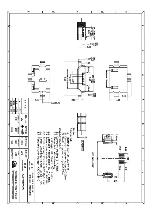
MICRO USB 5S 沉板1.0 2D无卷边
- 格式:pdf
- 大小:115.21 KB
- 文档页数:1

QY-9315S 主板硬件说明书版 本 号:V 1.1杭州启扬智能科技有限公司出品杭州启扬智能科技有限公司版权所有2008年7月杭州启扬智能科技有限公司目 录一、前言 (3)1、 公司简介........................................3 2、 QY-9315S 主板的使用建议. (3)二、系统组成 (4)2.1、主板资源.........................................4 2.2、主板接口及定义. (5)2.2.1、主板接口 (5)2.2.2、主板接口定义 (7)2.2.3、指示灯说明 (11)2.2.4、跳线说明....................................11 2.3、主板规格. (12)三、光盘...............................................14 四、软件描述.........................................14 五、附注. (14)杭州启扬智能科技有限公司一、 前言1、 公司简介:杭州启扬智能科技有限公司位于美丽的西子湖畔,是一家集研发、生产、销售为一体的高新技术产业。
公司致力于成为嵌入式解决方案的专业提供商,为嵌入式应用领域客户提供软硬件开发工具、嵌入式系统完整解决方案。
产品范围主要包括:Cirrus Logic EP9315系列ARM 主板/核心板、ATMEL 系列ARM 主板/核心板音/视频通用开发平台可运行Linux2.4/2.6、WinCE 4.2/5.0/6.0操作系统,并可根据客户需求开发各种功能组合的嵌入式硬件系统。
应用领域涉及:网络视频监控、网络视频点播、车载娱乐系统、手持娱乐系统客户的需求是公司发展的动力,公司将不断完善自身,与客户互助互惠,共同发展。
2、 QY-9315S 工业主板的使用建议:1) 使用主板之前,请务必首先阅读本说明书;2) 了解主板的基本结构和组成,包括硬件资源的分配,主板的各个引脚定义等等;3) 如果您需要在Linux 系统下进行设计开发,对主板进行程序烧录,除本文档外,还建议阅读另一篇文档《QY-9315S Linux 用户手册》;4) 如果您需要在WinCE 系统下进行设计开发,对主板进行程序烧录,除 本文档外,还建议阅读另一篇文档《QY-9315S WinCE 用户手册》;杭州启扬智能科技有限公司二、系统组成2.1、主板资源:QY-9315S 工业主板由单板结构构成。

MD0011-016PreliminaryPage 1 of 19The MICROS Wireless Bump Bar MWBB-10 and MWBB-20 User’s Guide This document describes the Micros Wireless Bump Bar (MWBB), a follow on to the popular Micros bump bar available in both 10 key and 20 key configurations. Topics include an overview, feature list, installation considerations, operation and dimensional drawings of the 10 key and 20 key mounting brackets.Overview (2)Battery Installation (4)Dongle Installation (5)Installation Considerations (6)Operation (7)Low Battery Indicator (8)Configuration Mode (8)Pairing Procedure (11)Opening the MWBB (12)MWBB FRUs (14)Specification Summary (17)MWBB-10 and MWBB-10 Bracket Dimensional Drawing (18)MBB-20 and MWBB-20 Bracket Dimensional Drawing....................................19OverviewThe new Wireless Bump Bars retain the same extruded aluminum housing and sealedend caps for protection from the kitchen environment. The MWBB-10 and MWBB-20use the same Duraswitch magnetic keys rated for up to 30 million operations.The wireless capability frees the Bump Bar from the issues of routing cables andextension cables, and the possible loss of functionality resulting from a damaged orcut USB interface cable.The AAA alkaline batteries will provide at least 3 months of operation.In addition, the wireless bump bars feature:•WirelessUSB Protocol 2.2•Keypress Confirmation LED•Flexible mounting orientation with supplied quick release brackets•Future optional belt clip will be available for the MWBB-10 Bump Bar•Low Battery Indicator.The included mounting bracket secures the bump bar to any counter surface andfeatures a thumbscrew lock for quick service. Each bump bar also features rubber feetto keep the unit stationary on a counter. The MWBB-10 will support an optional beltclip for portable use.The MWBB-10 and MWBB-20 kits include the USB dongle, mounting bracket andbatteries. The wireless bump bar and dongles are paired to the same 5-byte ID at thefactory. Install the batteries and connect the USB dongle to the KDS controller and it’sready to go.The 5-byte dongle ID is fixed. With over 64000 unique IDs possible, it is unlikely thatadjacent bump bars will interfere with one another.The Wireless Bump Bar can be paired to any Wireless Dongle by entering a sequenceof keystrokes at the Bump Bar. This can be used when either the bump bar or dongle isreplaced or in cases where the two bump bars communicate with the same dongle.A procedure changing the bump bar pairing can be found in the operation section ofthis document.Refer to the MICROS Wireless Bump Bar PMA for more information about KDSmounting options.Dimensional drawings for each mounting bracket can be found at the end of thisdocument.MD0011-016PreliminaryPage 2 of 19MD0011-016PreliminaryPage 3 of 19MICROS Wireless Bump Bar Kit ContentsThe MWBB-10 and MWBB-20 kits are shown in the Figure below.Figure 1: The MWBB-10 and MWBB-20 Kit ContentsEach kit includes a Dongle and Bump Bar paired with unique 5-byte IDs. To changethe Bump Bar ID, see page 11.MD0011-016PreliminaryPage 4 of 19Battery InstallationRefer to Figure 2 to remove the end cap and install the AAA batteries.When replacing the batteries, always use Alkaline AAA type batteries.Figure 2: Installing the BatteriesMD0011-016PreliminaryPage 5 of 19Dongle InstallationFigure 3 shows the MWBB Dongle attached to a USB input of the MICROS KDS controller.Figure 3: Installing the Wireless Bump Bar USB DongleTo the operating system, the MWBB Dongle appears as an USB Human InterfaceDevice (HID).Installation ConsiderationsBefore installing the mounting bracket(s) consider the following site related issues toensure the best possible functionality from the MWBB in an active RF environment.RangeDistances of up to 30 feet are possible when the dongle and bump bar are within‘line-of-sight’ of each other, with no obstructions in the path of the RF signals.As the number and type of obstructions between the dongle and bump barincrease, the range decreases. See the Classification of RF Obstructions sectionbelow for more detail.For best results, the bump bar should be positioned so that the black acrylic capalong the top edge is oriented towards the dongle.Classification of RF ObstructionsRF signals will encounter two types of obstructions that either weaken or reflectthe signal, depending on its material composition.The first type of obstruction is one that allows the signal to pass through, butattenuates, or weakens it. Some examples include walls constructed of wood,drywall, people, and concrete block. The amount of attenuation is proportional tothe total thickness of materials that must be penetrated by the RF signal travelingthe line-of-sight path.The second type of obstruction is one that reflects the RF signals, allowing little ornone to pass through. The reflected RF energy can cause interference even whenthe dongle and bump bar are located within line-of-sight. Any type of metallicsubstance falls into this category. This includes objects such as stainless steel foodpreparation areas, walk-in freezers, steel doors, and steel support beams.Local RF InterferenceThe RF signals emitted by the MWBB are located in the unlicensed 2.40 - 2.50GHz Industrial, ISM band. Nearby occupants of this band include microwaveovens (2.485 GHz), 802.11 b/g WiFi, cordless phones, IEEE 802.15.4 (WPAN),ZigBee, and other personal area networks. The MWBB should be located as farfrom these devices as possible.The greater the distance between the dongle and the bump bar, plus the greater thenumber of obstructions between the two devices may allow extraneous RFdevices to impact the operation of the bump bar.In cases where the site is too noisy in terms of RF interference, MICROSrecommends the use of the MBB-10 and MBB-20 wired Bump Bars.To install the bump bar mounting brackets, refer to the dimensional drawings at theend of this document.MD0011-016PreliminaryPage 6 of 19MD0011-016PreliminaryPage 7 of 19OperationFigure 4 points out the location of the Keystroke Confirmation LED and low battery indicator.Figure 4: Bump Bar Operator FeaturesKeystroke Confirmation LEDWhen a key is pressed, the Keystroke Confirmation LED turns on to provide visual confirmation that the keystroke was accepted by the Wireless Dongle.When the Wireless Dongle and Bump Bar are within range, the confirmation is immediate, with no delay between pressing the key and receiving the visual confirmation.If a delay between pressing a button and the LED flashing occurs, check the following.• A dongle paired to the same Bump Bar 5-byte ID is not installed in the KDScontroller.•The paired Dongle and Bump Bar are out of range, possibly due toobstructions or interference.•Weak or dead batteries. Check the Bump Bar low battery indicator on the nextpage. NOTICE: The LED brightness and speaker volume adjustments availablein the MICROS Wired Bump Bar are not available in the Wireless version.MD0011-016PreliminaryPage 8 of 19Low Battery IndicatorThe Low Battery indicator appears on the lens as shown in the illustration below. The Low Battery Indicator starts blinking when the battery voltage reaches 2.2V . •When the Low Battery Indicator is flashing Amber, replace the batteries.Figure 5: Low Battery Indicator Icon•If the Low Battery Indicator displays Red, the MWBB may not operate. The Red LED indicates the battery voltage is 2.0V .•When replacing batteries use AAA Alkaline Batteries Only .Configuration ModeThe Configuration Mode is enabled from the Keypad and allows you to configure settings such as Upper/Lower Case characters, Normal/Reverse Character Orientation, and selecting 2x5 or 2x10 operation. After changing a parameter, the Bump Bar exits Configuration Mode and turns off the Keystroke LED. To pair a Wireless Bump Bar to a different Wireless Dongle, see page 11.Lower Case CharactersSets all alpha characters to lower case at the selected orientation as shown below Figure 6.Figure 6: Lower Case Character ExampleTo select lower case characters:•Simultaneously press and hold the [1], [A], and [3] keys until the KeystrokeLED turns solid, then press [2], [1]. The Keystroke LED turns off.Upper Case CharactersSets all alpha characters at the selected orientation as shown in Figure 7.Figure 7: Upper Case Character ExampleTo select upper case characters:•Simultaneously press and hold the [1], [A], and [3] keys until the Keystroke LED turns solid, then press [2], [2]. The Keystroke LED turns off.Normal Character OrientationIn the Normal position, numeric characters appear in the top row, ascending from left to right. Alpha characters appear in the bottom row ascending from left to right as shown in Figure 8.Figure 8: Normal Character Orientation ExampleTo select Normal Character Orientation:•Simultaneously press and hold the [1], [A], and [3] keys until the Keystroke LED turns solid, then press [3], [1]. The Keystroke LED turns off.MD0011-016PreliminaryPage 9 of 19MD0011-016PreliminaryPage 10 of 19Reverse Character OrientationFor greater flexibility when mounting the Wireless Bump Bar, reverse character orientation places alpha and numeric keys in descending order from left to right as shown in Figure 9.Figure 9: Reverse Character Orientation ExampleTo select reverse character orientation:•Simultaneously press and hold the [1], [A], and [3] keys until the KeystrokeLED turns solid, then press [3], [2]. The Keystroke LED turns off.Keypad TypeThe MWBB-10 (2x5) and MWBB-20 (2x10) Bump Bars use the same control board and firmware. The Keypad Type selection determines if the control board supports a 2x5 or 2x10 keypad and is normally set at the factory.To select a 2x5 keypad:•Simultaneously press and hold the [1], [A], and [3] keys until the KeystrokeLED turns solid, then press [4], [1]. The Keystroke LED turns off.To select a 2x10 keypad:•Simultaneously press and hold the [1], [A], and [3] keys until the KeystrokeLED turns solid, then press [4], [2]. The Keystroke LED turns off.LED TestThe LED Test is used at the factory to exercise the Wireless Bump Bar LEDs. To run the LED Test:•Simultaneously press and hold the [1], [A], and [3] keys until the KeystrokeLED turns solid, then press [e].•The LED Test turns on the Keystroke and Battery Low Indicator.MD0011-016PreliminaryPage 11 of 19Pairing ProcedureThe MWBB Dongle and Bump Bar are paired to the same 5-Byte ID at the factory. Figure 6 shows an example of the ID labels placed on the Bump Bar and Dongle. Figure 10: Dongle and Wireless Bump Bar ID labels /w 5-Byte IDThe Wireless Dongle ID is fixed. However, the Wireless Bump Bar ID can be changed to pair with any Wireless Dongle ID. The procedure below describes how to change a Wireless Bump Bar ID to ‘ee21d’. For standard alphanumeric key locations, see Figure 11, below.•Simultaneously press and hold the [1], [A], and [3] keys until the KeystrokeLED turns solid, release, then press the [1] key.•The Confirmation LED remains on indicate the unit is ready for the 5-Byte ID.•Enter the Dongle 5-Byte ID. For example, [e], [e], [2], [1], and [d].•The Confirmation LED blinks as each character is entered, then turns offafter the 5th byte to indicate acceptance of the new ID Code.Figure 11: Wireless Bump Bar Alphanumeric Key Locations (Normal Orientation)MD0011-016PreliminaryPage 12 of 19Opening the MWBBThis section describes how to open the MWBB-10 or MWBB-20 and access theinternal components. The controller board does not contain user configurable jumpers or switches.Remove the Controller Board1.Remove the Batteries before opening the unit.2.Remove the pair of screws from the right side end-cap.The upper half of Figure 12, below shows the right side end-cap removed.The controller board is fitted in slots at the front and rear. The light pipe is part of the Low Battery Indicator.3.Avoid pulling on the Keypad Cable. Pull the board out far enough to accessthe cables as shown in the Figure below.Figure 12: Accessing the MWBB Controller BoardMD0011-016PreliminaryPage 13 of 194.To remove the Keypad Cable, be sure to position CN2 as shown on the leftside of Figure 13, below.Figure 13: Removing/Installing the Keypad Ribbon Cable5.Remove the Battery Cable from CN1.Install the Controller Board1.Refer to the top half of Figure 12 and position the board in the front and rearslots.2.Connect the Keypad Cable to CN2 and the battery holder cable to CN1.3.Place the controller board in the grooves located at the front and rear of thecase, then start to slide the board into the case.4.When installing the board, make sure the Keypad Cable does not becomebunched up around CN2. The upper half of Figure 12 shows the correct board position.Battery HolderFigure 14 shows how the battery holder is attached to the controller board through a short extension cable.Figure 14: Battery Holder and Extension CableMD0011-016PreliminaryPage 14 of 19MWBB FRUsThis section contains the FRUs available for the MWBB-10 and MWBB-20.Control Board, Wireless Bump Bar - PN 700634-201Wireless Bump Bar Controller Board XBRG29 (/w Firmware) used for the MWBB-10 or MWBB-20.Figure 15: Replacement MWBB Control BoardBattery Holder, Wireless Bump Bar - PN 700538-015Includes 2xAAA Battery Holder and Extension Cable.Figure 16: Replacement Battery Holder and Extension CableMD0011-016PreliminaryPage 15 of 19USB Receiver (Dongle), Wireless Bump Bar - PN 700879-205Replacement Wireless Bump Bar Dongle. Device ID shown for reference only. Figure 17: Replacement Wireless Bump Bar USB DongleEnd Caps - Wireless Bump Bar - PN 000160-020Replacement End Caps for the Wireless Bump Bar. Please note that the battery side end cap will undergo modifications to allow a coin to be used to replace the batteries.Figure 18: Replacement Wireless Bump Bar End CapsMD0011-016PreliminaryPage 16 of 19Bracket, MICROS 10-Key Bump BarMounting Bracket for both the 10 key MICROS wired and wireless bump bars.Figure 19: 10 Key Mounting BracketBracket, MICROS 20-Key Bump BarMounting Bracket for both the 20 key MICROS wired and wireless bump bars. Hole centers are compatible with current 3rd party KDS hardware.Figure 20: 20 Key Mounting BracketMD0011-016PreliminaryPage 17 of 19Specification Summary SpecificationsKeyswitch Type 2x5 or 2x10 Duraswitch PushGate ® keys rated to 30 millionactuations.Connectivity WirelessUSB Protocol 2.2 (2.4GHz).Batteries2 AAA Alkaline Batteries IP (IngressProtection)Rating55Dimensions(w/bracket) MWBB-10: 6.22”W x 2.87”D x 1.25”H (158mm x 73mm x 32mm)MWBB-20: 9.38”W x 2.87”D x 1.25”H (238mm x 73mm x32mm)Weight(w/bracket andbatteries)MWBB-10: 0.90 lbs. (0.41 kg) MWBB-20: 1.25 lbs. (0.57 kg) Environmental Operating Temperature: 0°C to 55°C (32°F to 131°F) Storage Temperature: -25°C to 80°C (-13°F to 176°F)Humidity: 90% relative humidity max.MD0011-016PreliminaryPage 18 of 19MWBB-10 and MWBB-10 Bracket Dimensional DrawingMD0011-016PreliminaryPage 19 of 19MBB-20 and MWBB-20 Bracket Dimensional Drawing。

DISCRETE WIRE/discretewire/micromate SYSTEMSMICRO MATE™ 1.00 mm PITCH SYSTEMS• Cable-to-board, cable-to-cable and cable-to-panel• Low profile design down to 3.2 mm• 28 and 30 AWG wire options in PVC or Teflon™ fluoropolymer wire• Up to 40 total crimp-style dual leaf contacts• Socket or terminal, single or double row• Rugged positive latching for increased retention•Vertical and right-angle mating headersComponents (ISS1, ISD1/CC09;IST1, IDT1, ISP1, IDP1/TC37)and tooling available:visit /toolingMICRO TM 2.7A m p s M A XS1SS/T1M, S1SDT/T1M/discretewireTIGER EYE™DISCRETE WIRE SYSTEMS• 0.80 mm, 1.27 mm and 2.00 mm pitch• 24 to 32 AWG in PVC or Teflon™ fluoropolymer wire; color coded wire available • Single or double ended assemblies • Up to 100 total positions• Shrouded, polarized and keyed for more rugged applications • Retention latching option for higher withdrawal forces • Optional screw downs• Crimp for automotive applications in development for 1.27 mm pitch (SFSD/FFSD) assemblies; contact*************************Hand tools available for low volume and semi-automatic mini applicators for self assembly; visit /toolingComponents available for build-it-yourselfdesign and application flexibility;please see chart aboveIDC cable assemblies with ruggedstrain relief and mating shrouded headers;visit/idc3.8AmpsM A XS2SD/T2MSESDT/TEM-L1SFSST/TFM/discretewireMINI MATE ® DISCRETE WIRE SYSTEMS• .100" (2.54 mm) pitch• Individually shrouded contacts • 2 to 50 total positions • Single and double row• 20 to 30 AWG PVC or Teflon™ fluoropolymer wire; color coded available • Keyed polarization• Rugged metal or plastic latching • Vertical or right-angle mating header• Sealed version on roadmap for harsh environmentsPOWER MATE ® DISCRETE WIRE SYSTEMS• .165" (4.19 mm) pitch• Individually shrouded contacts • 2 to 30 total positions • Single and double row• 16 to 24 AWG PVC or Teflon™ fluoropolymer wire • Keyed polarization • Rugged plastic latching • Single or double ended•Vertical or right-angle mating headerComponents (IPD1/CC79L/CC79R) and tooling available for application flexibility; visit/toolingComponents (IPBD/CC69L/CC69R) and tooling available; visit /tooling4.8AmpsMMSDT/IPL1MMSS/IPL1-RAPMSD/IPBTPMSST/IPBT-RA10.4AmpsM A X/discretewiremPOWER ® ULTRA MICRO POWER SYSTEMS• Micro 2.00 mm pitch cable-to-board and cable-to-cable solutions• Simplifies board layout and delivers power directly to active components • 2 – 10 total power blades• 16 and 18 AWG wire; color coded available • Plastic top latching or metal side latching options • Tin or 10 µ" Gold plated power blades; 30 µ" Gold plating available to meet specific regulations • PVC or high-temp Teflon™ fluoropolymer wire • Vertical and right-angle mating headers with optional weld tabsPOWERSTRIP™HIGH-POWER SYSTEMS• 5.00 mm and 6.35 mm pitch • 2 to 8 total dual blade contacts• 30 Amp signal/power combo with 4 total power, and 16 or 24 Tiger Eye™ signal positions • 10 – 16 AWG wire• Polarized with a rugged latching system • Single or double ended•Vertical and right-angle mating headersComponents (IMPCC/IMPC/CC489, IMPEC/IMPE/TC146) and tooling available for self assembly; visit/toolingComponents (IMS5/CC46L/CC46R, IMSC5/CC81L/CC81R,IPS6/CC10L/CC10R) and tooling available for flexible applications; visit /tooling1840AmpsM A XUMPE/UMPIUMPCT/UMPT-RAMPCC/MPTCMPSS/MPTRUGGEDIZING OPTIONSWELD TABSSignificantly increaseshear resistance ofconnector to PCBSHIELDING360° shielding reduces EMIGUIDE POSTSEasy and secure matingSCREW DOWNSSecure mechanicalattachment to the boardBOARD LOCKSBoards are mechanicallylocked togetherRETENTION PINSIncrease unmating forceby up to 50%FRICTION LOCKSMetal or plasticfriction locks increaseretention/withdrawal forcePOSITIVE LATCHINGManually activated latchesincrease unmating force byup to 200%• Designed forSignal Integrity• SuperiorImpedance Control• Reduced BroadsideCoupling• High-reliability• Four Points ofContact• Extreme MatingCycles• Best Cost• Reliable Performance• Post & Beam Contact• Mating/Alignment“Friendly”• Cost-effective• Micro Pitch• Dual Wipe Contact• Pass-throughApplications• Ultra-low Profile• High-reliability• High Mating Cycles• Multi-finger ContactCONTACT SYSTEMSMICRO-HYPERBOLOID/contact-systemsWILLINGNESS, SUPPORT AND EXPERTISEIndustry-Leading Customer Service • Quotes and samples in 24 hours • Prototype and processing assistance • Dedicated Application Specific Product engineers and techniciansFlexible, In-House Manufacturing • Global Operations, including multiple cable fabrication & assembly facilities • Quick-turn samples and prototypes • Custom & modified product supportSignal Integrity Expertise• Industry-leading engineering support for high-performance system design • Full system optimization assistance, including simulation, testing, analysis and evaluation/custom© 2023, SAMTEC, INC.。

7-Port Industrial USB 2.0 Hub with ESD & 350W Surge ProtectionProduct ID: ST7200USBMThis TAA compliant 7-port industrial USB 2.0 hub gives you the scalability you need in harsh industrial environments, product and repair labs, conference rooms or office workstations. Withits rugged industrial grade metal housing, it is designed to meet the advanced requirements of connecting a high number of devices in factories and office environments.Perfect for Harsh EnvironmentsThis industrial USB hub delivers reliable performance with a metal, heavy-duty housing. It supports wide-range 7-24V DC terminal block input, giving you the flexibility to power the hub as required, based on your own power input capabilities.Perfect for factory environments, the rugged hub also supports a wide operating temperature range (0°C to 55°C) and offers surge and ESD protection to each USB port, which can help prevent damage to your connected devices.Connect More USB DevicesDesigned for a high volume of connections, this robust USB 2.0 hub offers 7 connection ports, for connecting more USB devices and peripherals.Locate the Hub Where You Need It MostWith versatile installation options, you can install the hub where it’s best suited for your environment. With built-in mounting brackets and included DIN mount rails, you can securely mount the USB 2.0 hub to most surfaces such as a wall, under a desk or rack. offers an external power adapter, ITB20D3250, sold separately. The universal DC power adapter can be used as an alternative, back up or replacement power supply for ’s line of industrial USB hubs.Works with Older USB DevicesThe rugged USB hub supports the full 480 Mbps bandwidth of USB 2.0 and is backward compatible with previous USB devices.The ST7200USBM is backed by a 2-year warranty and free lifetime technical support.Certifications, Reports and Compatibility Applications•Ideal for tough conditions that are subject to large temperaturevariances, or where there’s a risk of physical damage•Great for industrial and manufacturing environments where only terminal block connection is preferred•Connect a variety of USB devices such as industrial printers or cameras, plus fast-charge your smartphone and tablet•Mount to a wall near or under a desk surface in a Lab, Service Repair area or office area connecting multiple USB peripherals•Use in a conference or meeting room utilizing multiple USBperipherals or for charging several mobile devicesFeatures•Protects your connected devices with 15kV Air and 8kV Contact ESD protection•Surge protection of 350W on the downstream and upstream USB ports•Mount industrial USB 2.0 hub where required with built-in mounting brackets or included DIN rails•Offers flexible, wide-range power inputs with a 7-24V DC terminalblock•Adds seven USB 2.0 ports from a single USB connectionWarranty 2 YearsHardware Bus Type USB 2.0Chipset ID Terminus - FE2.1Industry Standards USB 2.0Interface USB 2.0Ports7Performance ESD Protection+/-15kV (Air)+/-8kV (Contact)Maximum Data Transfer Rate Up to 480MbpsMTBF170,227 HoursSurge Protection350W on the DFP and UFPConnector(s)External Ports 1 - Terminal Block (2 Wire)1 - USB B (4 pin) Female7 - USB Type-A (4 pin) USB 2.0 Female Software OS Compatibility OS independent; No software or drivers required System and Cable Requirements Any computer with a USB 2.0 portSpecial Notes /RequirementsIndicators LED Indicators 1 - PowerPower Input Voltage7 ~ 24 DCPower Source Terminal BlockEnvironmental Humidity5~95% RHOperating Temperature0°C to 55°C (32°F to 131°F)Storage Temperature-20°C to 85°C (-4°F to 185°F)Color BlackPhysicalCharacteristicsMaterial SteelProduct Height 1.4 in [3.6 cm]Product Length 5.2 in [13.3 cm]Product Width 2.4 in [61.5 mm]Weight of Product10 oz [283 g]PackagingPackage Height 2 in [51 mm]InformationPackage Length 5.9 in [15.1 cm]Package Width8.5 in [21.6 cm]Shipping (Package) Weight17.2 oz [488 g]What's in the Box Included in Package 1 - USB 2.0 Hub2 - DIN rail mounting bracket1 - 6 ft [1.8 m] USB-B w/screw lock to USB-A cable1 - Screw kit1 - Instruction ManualProduct appearance and specifications are subject to change without notice.。