机械工艺夹具毕业设计50气缸套法兰耳零件的工艺规程及钻4-12孔的工装夹具设计
- 格式:doc
- 大小:483.50 KB
- 文档页数:27

Title The flange plate processing technology and fixture designAbstractThe design is based on the body parts of the processing order of the processes and some special fixture design. Body parts of the main plane of the surface and pore system. In general, the plane guarantee processing precision than that of holes machining precision easy. Therefore, this design follows the surface after the first hole principle. Plane with holes and the processing clearly divided into roughing and finishing stages of holes to ensure machining accuracy. Datum selection box input shaft and the output shaft of the supporting hole as a rough benchmark, with top with two holes as a precision technology reference. Main processes arrangements to support holes for positioning and processing the top plane, and then the top plane and the supporting hole location hole processing technology. In addition to the follow-up processes individual processes are made of the top plane and technological hole location hole and plane processing. Supported hole processing using the method of coordinate boring. The whole process of processing machine combinations were selected. Selection of special fixture fixture, clamping means more choice of pneumatic clamping, clamping reliable, institutions can not be locked, so the production efficiency is high, suitable for large batch, line processing, can meet the design requirements.Keywords Frange plate; fixture;, design1 (1)1.1 (2)1.1.1 (2)1.1.2 (2)1.2 (3)1.3 (3)1.3.1 (3)1.3.2 (3)1.4 (3)1.5 (5)1.6 (6)1.7 (6)2 4- 10 (16)2.1 (16)2.2 (17)2.2.1 (17)2.2.2 (17)2.3 (18)2.4 (19)2.5 (19) (21) (22) (24)11.11.1.111.1.21 42 mRa2.32 10 4- 10 mRa2.31.21.31.3.1121.3.21.4c 9080 0.4%—1.1% 0.25%—0.5% mg 20010203040 87506070 82804- 10 90 100102030 4- 10 4050 87607080 829010010203040 87506070 8280 4- 10901001.5(1)HT200(2)2.2-5 HT200 HB 170—24121 3.2.23mm 4.3~7.1 mm 0.2 3.2.27 mm 28.02.3.59 mm 1 CT7 2.3.9 mm 6.11.6mm 1000mm [2] 6—7 CA6140 [2] 4—3 [2]1.71020.HT200 CA6140YG61.1 CA6140 200mm 1.30 H B =mm mm 2516 mm 5.4 0V =012 0 =06 v K =090 'v K =010 s =00 s r =mm 8.0pa mm 2f1.4mm 16mm 25 p a mm 4 100 400 f =0.5 1.0r mmCA6140 4.2—9f =0.7rmm 1—30 CA6140 max F =3530N1.21 174 207HBS p a mm 4 f 75.0 r mm r K =045 R F =950Nf F roFf K =1.0 sFf K =1.0 krFf K =1.17 1.29—2f F =95017.1 =1111.5N1-2f =r mm 7.01.9mm 5.1 T =min 60V1.11 6YG 200 219HBS p a mm 4 f r mm 75.0 V =min 63mtv K =1.0 mv K =0.92 sv K 0.8 Tv K =1.0 Kv K =1.0 1.28'0V =t V v K =63 0.10.184.092.00.10.1 1-3min48m n =D V c '1000=127481000 =120min r 1-4 CA61400n =125minr c VcV =1000c Dn =1000125127 min50m 1-51.25 HBS =160 245 p a mm 3 f r mm 75.0 min 50m VC P =KW7.1 krPc k =0.73 Pc r K 0=0.9CP =1.773.0 =1.2KW 1-61.30 n =min 125r E P =KW 9.5 C P E P C620—1p a =3.75mm f =r mm 7.0 n =min 125r =s r 08.2 V =min 50m 30 87YG61.1 C6140 200mm 1.30 H B =mm mm 2516 mm 5.4 0V =012 0 =06 v K =090 'v K =010 s =00 s r =mm 8.0pa mm 5.2p a =25.2=mm 25.1 f1.4mm 16mm 25 p a mm 4 100 400 f =0.5 1.0rmm CA6140 4.2—9f =0.7rmm1—30 CA6140 max F =3530N1.21 174 207HBS p a mm 4 f 75.0 r mm r K =045 R F =950Nf F roFf K =1.0 sFf K =1.0 krFf K =1.17 1.29—2f F =95017.1 =1111.5Nf =r mm 7.01.9mm 5.1 T =min 60V1.11 15YT 200 219HBS p a mm 4 f r mm 75.0 V =min 63mtv K =1.0 mv K =0.92 sv K 0.8 Tv K =1.0 Kv K =1.0 1.28'0V =t V v K =63 0.10.184.092.00.10.1 3-12min 48m n =D V c '1000=127100048 =120minr 3-13 CA61400n =125minr c VcV =1000c Dn =1000125127 min50m 3-141.25 HBS =160 245 p a mm 3 f r mm 75.0 min 50m VC P =kw7.1 krPc k =0.73 Pc r K 0=0.9C P =1.773.0 =1.2kw1.30 n =min 125r E P =kw 9.5 C P E P CA6140p a =1.25mm f =r mm 7.0 n =min 125r =s r 08.2 V =min 50m .nfl t3-15 L =l +y + l =mm127 1.26 y + =mm 1 L =126+1=mm128m t =7.0125127 =min 4.1 40YG61.1 C6140 200mm 1.30 H B =mm mm 2516 mm 5.4 0V =012 0 =06 v K =090 'v K =010 s =00 s r =mm 8.0pa mm 5.2p a =25.2=mm 25.1 f1.4mm 16mm 25 p a mm 4 100 400 f =0.5 1.0rmm CA6140 4.2—9f =0.7rmm 1—30 CA6140 max F =3530N1.21 174 207HBS p a mm 4 f 75.0 r mm r K =045 R F =950Nf F roFf K =1.0 sFf K =1.0 krFf K =1.17 1.29—2f F =95017.1 =1111.5Nf =r mm 7.01.9mm 5.1 T =min 60V1.11 15YT 200 219HBS p a mm 4 f r mm 75.0 V =min 63mtv K =1.0 mv K =0.92 sv K 0.8 Tv K =1.0 Kv K =1.0 1.28'0V =t V v K =63 0.10.184.092.00.10.1 3-12min 48m n =D V c '1000=127100048 =120minr 3-13 CA61400n =125minr c VcV =1000c Dn =1000125127 min50m 3-141.25 HBS =160 245 p a mm 3 f r mm 75.0 min 50m VC P =kw7.1 krPc k =0.73 Pc r K 0=0.9C P =1.773.0 =1.2kw1.30 n =min 125r E P =kw 9.5 C P E P CA6140p a =1.25mm f =r mm 7.0 n =min 125r =s r 08.2 V =min 50m .nfl t3-15 L =l +y + l =mm127 1.26 y + =mm 1 L =126+1=mm128m t =7.0125127 =min 4.1 502040 82YG61.1 C6140 200mm 1.30 H B =mm mm 2516 mm 5.40V =012 0 =06 v K =090 'v K =010 s =00 s r =mm 8.0pa mm 5.2p a =25.2=mm 25.1 f1.4mm 16mm 25 p a mm 4 100 400 f =0.5 1.0rmm CA6140 4.2—9f =0.7rmm 1—30 CA6140 max F =3530N1.21 174 207HBS p a mm 4 f 75.0 r mm r K =045 R F =950Nf F roFf K =1.0 sFf K =1.0 krFf K =1.17 1.29—2f F =95017.1 =1111.5Nf =r mm 7.01.9mm 5.1 T =min 60V1.11 15YT 200 219HBS p a mm 4 f r mm 75.0 V =min 63mtv K =1.0 mv K =0.92 sv K 0.8 Tv K =1.0 Kv K =1.0 1.28'0V =t V v K =63 0.10.184.092.00.10.13-12min 48m n =D V c '1000=127100048 =120minr 3-13 CA61400n =125minr c VcV =1000c Dn =1000125127 min 50m 3-141.25 HBS =160 245 p a mm 3 f r mm 75.0 min 50m VC P =kw7.1 krPc k =0.73 Pc r K 0=0.9C P =1.773.0 =1.2kw1.30 n =min 125r E P =kw 9.5 C P E P CA6140p a =1.25mm f =r mm 7.0 n =min 125r =s r 08.2 V =min 50m .nfl t3-15 L =l +y + l =mm127 1.26 y + =mm 1 L =126+1=mm128m t =7.0125127 =min 4.180 4- 10Z525 GB1436-85 22 10.4-2 10mm 0.20 0.35r mm rmm f 30.0 2 10.4-9min0m k f a T d c v v y x p m z v v v v3-20 125.0,55.0,0,25.0,1.8 m y x z c v v v v T=35minv =55.00125.025.03.053571.8 =1.6minmn =714.36.11000 =72min r min120r n 1000714.3120 v =2.64minmt =s 203.022282 4- 102.14- 10 Z525”2.22.2.182 822.2.210 D=1028.4F=C F d 0F z f F y k F ……………………………………3.1C F =420 Z F =1.0, y F =0.8, f=0.35k F =(07.1)190200()1903.1 F n HB F=420 1.00.8300.35 1.072123()NT=C T d 0T Z f T y k T: C T =0.206, Z T =2.0, y T =0.8T=0.206 2.00.8300.35 1.0717.34()N M P m =KW d T V 726.083095.1634.17300K=K 1K 2K 3K 4K 1 1.5;K 2 1.1;K 3 , 1.1;K 4 , 1.1F /=KF=1.5)(423921231.11.11.1N T=17.34 N M:F 1=N L T 267106534.173 1.0 f F f =4416)(6.4411.0N F f > F 12.3ZZmm 05.0~03.02 . mm 04.02 .P297mm008.03 mmDW 142.016.005.008.004.0125.022222252423222 .533.032142.0.2.43.13.22.51234[1] 1982. (1)[2] [M] 1984 20-23[3] [M] 1983 42-50[4] [ ] 1992[5] 1 [M] 1991[6] [M] 1979[7] [M] 1990[8] [M] 1994[9] [M] 1984[10] [M] 2002[11] , ( ) [M], ,2003.1[12] [M] 1995[13] [M] 1980[14] [M] 1991[15] [M] 2000 9-19[16] , , , ,1979.12[17] 2005 4-17[18] Machine Tools N.chernor 1984.[19] Machine Tool Metalworking John L.Feirer 1973.[20] Handbook of Machine Tools Manfred weck 1984 .[21] Sors l.fatigue design of machine components.oxford:pergramon press.1971!。


江西农业大学工学院《机械制造工艺》课程设计说明书课题名称: 法兰盘工艺及其夹具设计专业:机械设计制造及其自动化班级:机制082姓名:学号:指导老师:2011 年 1月20日姓名班级机制082 学号20081015设计题目法兰盘工艺及其夹具(钻孔)设计指导老师零件名称法兰盘材料HT200生产类型中批量生产毛坯铸件生产纲领年生产量4200件设计任务法兰盘零件加工工艺规程,钻4XΦ20阶梯孔的钻床专用夹具设计。
其余9技术要求刻字字形高,刻线宽;面抛光;外圆无光镀铬。
二、机械制造工艺课程设计任务书目录1、序言.............................................................................. .. (2)2、设计任务 (3)3、工艺规程设计 (4)3.1定位基准的选择 (4)3.2工件表面加工方法的选择 (5)3.3制定工艺路线 (7)3.4确定加工余量、工序尺寸及毛坯尺寸,设计、绘制毛坯图…………4 夹具设计 (45)4.1设计要求 (45)4.2夹具设计的有关计算 (45)4.3夹具结构设计及操作简要说明 (46)5、结束语 (47)6、参考文献 (47)1、序言机械制造工艺课程设计是在我们完成了全部基础课、技术基础课、大部分专业课以及参加了生产实习之后进行的。
这是我们在进行毕业设计之前对所学各课程的一次深入的综合性的复习,也是一次理论联系实际的训练,因此,它在我们四年的大学生活中占有重要的地位。
通过本次课程设计,应该得到下述各方面的锻炼:1 能熟练运用机械制造工艺设计中的基本理论以及在生产实习中学到的实践知识,正确地解决一个零件在加工中的定位、夹紧以及工艺路线安排、工艺尺寸确定等问题,保证零件的加工质量。
2 提高结构设计的能力。
通过设计夹具的训练,应当获得根据被加工零件的加工要求,设计出高效、省力、经济合理而且能保证加工质量的夹具的能力。
摘要工艺学是研究机械加工工艺技术和夹具设计为主的技术学科,具有很强的实践性,要求学习过程中应紧密联系生产实践,同时它又具有很强的综合性。
本次毕业设计研究的课题是法兰盘加工工艺及夹具的设计,主要内容如下:首先,对零件进行分析,主要是零件作用、结构和工艺的分析,通过零件分析可以了解零件的基本情况,而工艺分析可以知道零件的加工表面和加工要求。
根据零件图提出的具体加工要求,确定毛坯的制造形式和尺寸。
第二步,进行基面的选择,确定加工过程中的粗基准和精基准。
根据选好的基准,制定工艺路线方案,通常情况下制定两种以上的工艺路线方案,通过工艺方案的比较分析,再确定出可以使零件的几何形状、尺寸精度及位置精度等技术要求得到合理保证的工艺路线方案。
第三步,根据已经确定的工艺路线,选择加工设备及工艺装备,再确定每一工步的切削用量及时间定额。
第四步,设计工序Ⅶ—钻法兰盘4mm斜孔的夹具。
先提出夹具设计任务,选择定位基准,再确定夹具结构方案,然后开始切削力、夹紧力的计算和定位误差的分析。
最后,把整个设计过程整理为设计说明书和图纸,至此整个设计基本完成。
关键词:法兰盘;加工工艺;夹具设计。
AbstractTechnology is the study of machining fixture design technology and technology-based disciplines, with a very practical, requiring close contact with the learning process should be productive practice, but it also has a strong and comprehensive.The issue is the graduation of flange and fixture design process, the following key elements: First, the analysis of parts, mainly the role of parts, structural and process analysis, part by part analysis to understand the basic situation, The process analysis to know the machining surface and machining requirements. According to the specific part drawing processing requirements, to determine the manufacture of blank forms and dimensions.The second step, the choice of the base surface to determine the processing of coarse and fine reference base. According to the chosen benchmark, the development process route programs, usually two or more of the process line development program, through the process of comparative analysis of the program, and then determine the geometry can make the part shape, size and location accuracy of a reasonable accuracy and other technical requirements programs to ensure the process route.The third step, according to process routes have been identified, select the processing equipment and process equipment, and then determine the amount of each process step of cutting and time fixed for the rough.The fourth step, the design process Ⅶ - 4mm Flange drilling inclined holes of the fixture. To present the fixture design task, select locating datum, and then determine the fixture structure solution, and then began cutting force, clamping force calculation and analysis of positioning error.Finally, the process of finishing the entire design specifications and drawings for the design, bringing the whole design is basically completed.Keywords: Flange; Processing Technology; Fixture Design.第1章绪论1.1机械加工工艺的发展现状随着机械制造业的发展和科学技术的进步,机械制造工艺的内涵和面貌下不断发生变化,近一二十年的技术进展主要表现在以下几方面:(1)常规工艺的不断优化常规工艺的方向是实现高效化、精密化、强韧化、轻量化,以形成优质高效、低耗少污染的先进实用工艺为主要目标,同时实现工艺设备、辅助工艺、工艺材料、检测控制系统的成套工艺服务,使优化工艺易于为企业所采用。

摘要气缸套是发动机的重要组成部分,其性能直接影响发动机的整体性能,甚至影响到机器的性能。
气缸套是发动机的重要组成部分,其性能直接影响到发动机的整体性能,甚至影响到机器的性能。
因此,气缸套生产制造是非常重要的内容。
气缸套制造工程是一个系统工程,必须满足机器性能的要求,同时必须满足生产纲领的实际需要。
缸套的加工工艺过程必须合理,满足实际需要。
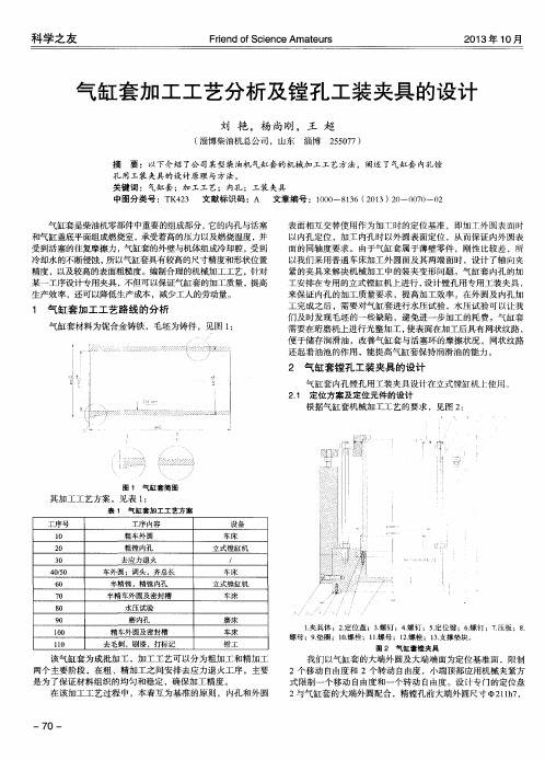
通过分析气缸套的结构原理,设计气缸套的加工工艺。
由于气缸套加工精度要求高,设计粗加工和精加工的加工工艺必须合理并且满足要求。
朝着加工的气缸套符合机器性能要求,对缸套夹具零件加工和并且设计一套加工工艺路线,来达到工件制造质量和装配精度的需求。
根据发动机缸套零件形状及加工特点,所设计该零件机床加工夹具要考虑缸套孔的精确度,能否夹紧,夹紧后能否自锁以及夹紧力的调节。
[1]夹具必须能够保证零件加工精度,可以提高生产率、使用方便、良好的工艺性同时还能减少加工成本。
关键词:气缸套,加工工艺,夹具ABSTRACTThe engine is the core parts of the machine, the machine is powered. The cylinder is an important part of the engine, its performance directly affects the overall performance of the engine, and even affect the working performance of the machine. Therefore, the cylinder sleeve manufacturing is very important content.Cylinder sleeve manufacturing engineering is system engineering, must meet the actual needs of machine performance requirements, and must also meet the production program. Machining process of cylinder must be reasonable, to meet the actual needs. By analyzing the structure and principle of cylinder liner, cylinder sleeve design process. Since the cylinder sleeve with high precision machining, machining process design of rough machining and finish machining must be reasonable and meet the requirements. In order to meet the processing cylinder machine performance requirements, formulate cylinder clamp parts processing and adjusting the process, ensure the fixture parts manufacturing quality and assembly precision. According to the shape of cylinder engine parts and processing characteristics, the design of the machine tool fixture parts to consider whether the accuracy of cylinder hole, clamping, clamping adjustment can self locking and clamping force. Meet the fixture should be to ensure that the work piece machining precision, can improve the productivity, better technology, use of the good, the economy is better.Key Words:Cylinder liner,Processing technology,Fixture目录第1章绪论 (1)1.1 课题的目标及意义 (1)1.2 缸套概述 (1)1.3 设计要求 (1)第2章零件的工艺分析 (3)2.1 零件的技术要求 (3)2.2 零件的作用 (5)2.3 零件的工作条件 (5)第3章工艺规程设计 (6)3.1 基准面的选择 (6)3.2 制定工艺路线 (7)3.3 机械加工余量、工序尺寸及毛坯尺寸的确定 (8)3.4 确定切削用量及基本工时 (10)第4章夹具设计 (12)4.1 夹具概述 (12)4.2 定位方案的选定 (13)4.3 确定夹紧装置 (13)4.4 定位误差分析 (13)4.5 夹具装配图 (14)结论 (15)参考文献 (16)致谢 (17)III第1章绪论1.1课题的目标及意义制造业是国家经济的发展的支柱产业,直接影响这个国家创新能力和综合国力,以致不被全球化的经济发展所淘汰。
机械制造技术基础课程设计说明书设计题目:法兰盘零件的机械加工工艺规程及夹具设计院:学 院:学系:院 系:院系:班 级:级:班姓 名:名:姓指导教师:指导教师:机械制造技术基础课程设计任务书题目:法兰盘零件的机械加工工艺规程及夹具设计内容:1、零件图 1张2、毛坯图 1张3、机械加工工序卡 13张4、机械加工过程卡 1张5、夹具结构设计装配图 1张6、课程设计说明书 1份录目目 录1 1 零 件 的 分 析 .......................................................零件的作用........................................................ (1)1.1零件的作用零件的工艺分析 (1)1.2 零件的工艺分析1 2 工 艺 规 程 设 计 .................................................... (1)2.1确定毛坯的制造形式确定毛坯的制造形式................................................ (1)基面的选择........................................................2.2基面的选择制定工艺路线...................................................... (2)2.3制定工艺路线 (3)机械加工余量,工序尺寸及毛坯尺寸的确定............................2.4机械加工余量,工序尺寸及毛坯尺寸的确定确定切削用量及基本工时............................................ (5)2.5确定切削用量及基本工时26 3 夹具设计 ............................................................ (26)3.1问题的提出问题的提出....................................................... (26)夹具设计.........................................................3.2夹具设计参考文献 (29)1 零 件 的 分 析1.1零件的作用题目所给定的零件是CA6140车床上的法兰盘(见附图1), 法兰盘起联接作用是车床上的重要零件。
气缸缸套机械加工工艺规程及夹具的设计毕业论文目录一、内容概述 (2)1.1 研究背景与意义 (3)1.2 国内外研究现状 (4)1.3 论文结构安排 (5)二、气缸缸套机械加工工艺基础 (6)2.1 气缸缸套的工作原理及结构特点 (8)2.2 机械加工方法的选择原则 (9)2.3 加工精度与表面质量要求 (10)三、气缸缸套机械加工工艺规程设计 (11)3.1 工艺流程设计 (13)3.2 加工工艺参数确定 (15)3.3 机床设备选择与配置 (16)3.4 工艺文件编制 (17)四、气缸缸套机械加工夹具设计 (18)4.1 夹具的功能与分类 (20)4.2 常用夹具结构形式 (21)4.3 夹具设计要点 (22)4.4 夹具的精度与稳定性保证 (23)五、实例分析 (24)5.1 某型号气缸缸套的机械加工工艺规程设计 (25)5.2 某型号气缸缸套的夹具设计实例 (26)六、结论与展望 (28)6.1 研究成果总结 (29)6.2 存在问题与不足 (30)6.3 未来发展趋势与展望 (30)一、内容概述本毕业论文旨在深入探讨气缸缸套机械加工工艺规程及夹具设计的相关问题。
随着工业技术的不断进步,气缸缸套作为内燃机的核心部件,其加工质量和效率对于发动机的整体性能具有至关重要的影响。
对气缸缸套机械加工工艺规程及夹具设计的研究,不仅有助于提高发动机的生产质量,还有利于推动工业制造的持续发展。
本文首先介绍了气缸缸套的基本概念和用途,以及其在发动机中的重要地位。
详细阐述了气缸缸套的机械加工工艺规程,包括加工前的准备、加工过程中的工艺流程、工艺参数的选择与优化等。
在此基础上,重点探讨了夹具设计的原理、方法和步骤,分析了夹具设计在气缸缸套加工中的重要性及其对加工质量的影响。
气缸缸套的基本概述:介绍气缸缸套的定义、功能、材料及其在内燃机中的地位。
机械加工工艺规程:详细阐述气缸缸套的机械加工工艺过程,包括加工前的准备工作(如材料准备、设备检查等)、加工过程中的工艺流程(如粗加工、精加工等)、工艺参数的选择与优化等。
前言加工工艺及夹具毕业设计是对所学专业知识的一次巩固,是在进行社会实践之前对所学各课程的一次深入的综合性的总复习,也是理论联系实际的训练。
机床夹具已成为机械加工中的重要装备。
机床夹具的设计和使用是促进生产发展的重要工艺措施之一。
随着我国机械工业生产的不断发展,机床夹具的改进和创造已成为广大机械工人和技术人员在技术革新中的一项重要任务。
1.1课题背景及发展趋势材料、结构、工艺是产品设计的物质技术基础,一方面,技术制约着设计;另一方面,技术也推动着设计。
从设计美学的观点看,技术不仅仅是物质基础还具有其本身的“功能”作用,只要善于应用材料的特性,予以相应的结构形式和适当的加工工艺,就能够创造出实用,美观,经济的产品,即在产品中发挥技术潜在的“功能”。
技术是产品形态发展的先导,新材料,新工艺的出现,必然给产品带来新的结构,新的形态和新的造型风格。
材料,加工工艺,结构,产品形象有机地联系在一起的,某个环节的变革,便会引起整个机体的变化。
工业的迅速发展,对产品的品种和生产率提出了愈来愈高的要求,使多品种,对中小批生产作为机械生产的主流,为了适应机械生产的这种发展趋势,必然对机床夹具提出更高的要求。
1.2 夹具的基本结构及夹具设计的内容按在夹具中的作用,地位结构特点,组成夹具的元件可以划分为以下几类:(1)定位元件及定位装置;(2)夹紧元件及定位装置(或者称夹紧机构);(3)夹具体;(4)对刀,引导元件及装置(包括刀具导向元件,对刀装置及靠模装置等);(5)动力装置;(6)分度,对定装置;(7)其它的元件及装置(包括夹具各部分相互连接用的以及夹具与机床相连接用的紧固螺钉,销钉,键和各种手柄等);每个夹具不一定所有的各类元件都具备,如手动夹具就没有动力装置,一般的车床夹具不一定有刀具导向元件及分度装置。
反之,按照加工等方面的要求,有些夹具上还需要设有其它装置及机构,例如在有的自动化夹具中必须有上下料装置。
专用夹具的设计主要是对以下几项内容进行设计:(1)定位装置的设计;(2)夹紧装置的设计;(3)对刀-引导装置的设计;(4)夹具体的设计;(5)其他元件及装置的设计。
设计说明书题目:气缸套法兰耳零件的工艺规程及钻4-Ф12孔的工装夹具设计学生:学号:专业:班级:指导老师:摘要本次设计内容涉及了机械制造工艺及机床夹具设计、金属切削机床、公差配合与测量等多方面的知识。
气缸套法兰耳零件的加工工艺规程及其钻4-Φ12孔的夹具设计是包括零件加工的工艺设计、工序设计以及专用夹具的设计三部分。
在工艺设计中要首先对零件进行分析,了解零件的工艺再设计出毛坯的结构,并选择好零件的加工基准,设计出零件的工艺路线;接着对零件各个工步的工序进行尺寸计算,关键是决定出各个工序的工艺装备及切削用量;然后进行专用夹具的设计,选择设计出夹具的各个组成部件,如定位元件、夹紧元件、引导元件、夹具体与机床的连接部件以及其它部件;计算出夹具定位时产生的定位误差,分析夹具结构的合理性与不足之处,并在以后设计中注意改进。
关键词:工艺、工序、切削用量、夹紧、定位、误差。
ABSTRCTThis design content has involved the machine manufacture craft and the engine bed jig design, the metal-cutting machine tool, the common difference coordination and the survey and so on the various knowledge.The reduction gear box body components technological process and its the processing ¢140 hole jig design is includes the components processing the technological design, the working procedure design as well as the unit clamp design three parts. Must first carry on the analysis in the technological design to the components, understood the components the craft redesigns the semi finished materials the structure, and chooses the good components the processing datum, designs the components the craft route; After that is carrying on the size computation to a components each labor step of working procedure, the key is decides each working procedure the craft equipment and the cutting specifications; Then carries on the unit clamp the design, the choice designs the jig each composition part, like locates the part, clamps the part, guides the part, to clamp concrete and the engine bed connection part as well as other parts; Position error which calculates the jig locates when produces, analyzes the jig structure the rationality and the deficiency, and will design in later pays attention to the improvement.Keywords: The craft, the working procedure, the cutting specifications, clamp, the localization, the error目录序言 (1)一. 零件分析 (2)1.1 零件作用 (2)1.2零件的工艺分析 (3)二. 工艺规程设计 (3)2.1确定毛坯的制造形式 (3)2.2基面的选择传 (3)2.3制定工艺路线 (3)2.4机械加工余量、工序尺寸及毛坯尺寸的确定 (4)2.5确定切削用量及基本工时 (5)三夹具设计 (17)3.1问题的提出 (17)3.2夹具设计 (17)3.3切削力及夹紧力计算 (17)3.4定位误差分析 (18)3.5夹紧误差 (18)3.6夹具设计及操作简要说明 (18)总结 (21)致谢 (22)参考文献 (23)序言机械制造业是制造具有一定形状位置和尺寸的零件和产品,并把它们装备成机械装备的行业。
机械制造业的产品既可以直接供人们使用,也可以为其它行业的生产提供装备,社会上有着各种各样的机械或机械制造业的产品。
我们的生活离不开制造业,因此制造业是国民经济发展的重要行业,是一个国家或地区发展的重要基础及有力支柱。
从某中意义上讲,机械制造水平的高低是衡量一个国家国民经济综合实力和科学技术水平的重要指标。
气缸套法兰耳零件的加工工艺规程及其钻4—Ф12孔的夹具设计是在学完了机械制图、机械制造技术基础、机械设计、机械工程材料等进行课程设计之后的下一个教学环节。
正确地解决一个零件在加工中的定位,夹紧以及工艺路线安排,工艺尺寸确定等问题,并设计出专用夹具,保证零件的加工质量。
本次设计也要培养自己的自学与创新能力。
因此本次设计综合性和实践性强、涉及知识面广。
所以在设计中既要注意基本概念、基本理论,又要注意生产实践的需要,只有将各种理论与生产实践相结合,才能很好的完成本次设计。
本次设计水平有限,其中难免有缺点错误,敬请老师们批评指正。
一、零件的分析1.1零件的作用气缸套法兰耳的作用,待查1.2 零件的工艺分析气缸套法兰耳有2组加工面他们有位置度要求。
这2组加工面的分别为1,以外圆为基准的加工面,这组加工面包括,外圆自身和端面,和内圆,2:一个是以内圆为基准的加工面,这个主要是外圆的加工和各个孔的钻削。
二. 工艺规程设计2.1确定毛坯的制造形式零件的材料为45,根据生产纲领以及零件在工作过程中所受的载荷情况,选用锻造。
2.2基面的选择的选择基面的选择是工艺规程设计中的重要工作之一。
基面选择的正确合理,可以使加工质量得到保证,生产率得到提高。
否则,加工工艺过程中会问题百出。
粗基准的选择:对法兰这样的回转体零件来说,选择好粗基准是至关重要。
对回转体零件我们通常以外圆作为粗基准。
精基准的选择:精基准的选择要考虑基准重合的原则,设计基准要和工艺基准重合。
因此我们采用孔做为精基准2.3制定工艺路线制订工艺路线的出发点,应当是使零件的几何形状、尺寸精度及位置精度等技术要求能得到合理的保证。
通过仔细考虑零件的技术要求后,制定以下两种工艺方案:方案一工序Ⅰ:锻造工序Ⅱ:退火工序Ⅲ:粗车,半精车,精车内孔工序Ⅳ:Φ210外圆及其端面,车退刀槽R5工序Ⅴ:Φ220外圆及其端面,车退刀槽R5工序Ⅵ:铣台阶面工序Ⅶ:铣平台面工序Ⅷ:铣平台面周边工序Ⅸ:钻4-Ф12孔工序X:质检、入库方案二工序Ⅰ:锻造工序Ⅱ:退火工序Ⅲ:Φ210外圆及其端面,车退刀槽R5工序Ⅳ:Φ220外圆及其端面,车退刀槽R5工序Ⅴ:粗车,半精车,精车内孔工序Ⅵ:铣台阶面工序Ⅶ:铣平台面工序Ⅷ:铣平台面周边工序Ⅸ:钻4-Ф12孔工序X:质检、入库工艺方案一和方案二的区别在于方案一把内孔加工放到了前面,根据粗基准选择原则,我们知道方案一相对合理。
具体的工艺路线如下工序Ⅰ:锻造工序Ⅱ:退火工序Ⅲ:粗车,半精车,精车内孔工序Ⅳ:Φ210外圆及其端面,车退刀槽R5工序Ⅴ:Φ220外圆及其端面,车退刀槽R5工序Ⅵ:铣台阶面工序Ⅶ:铣平台面工序Ⅷ:铣平台面周边工序Ⅸ:钻4-Ф12孔工序X:质检、入库2.4 机械加工余量、工序尺寸及毛坯尺寸的确定法兰零件材料为45,生产类型为大批量生产,采用锻造。
1、法兰的外圆和端面因轴套的外圆和端面的精度要求都不是很高,其加工余量为2.5mm 。
3、法兰的内孔毛坯为空心,锻造出孔。
孔的精度要求介于IT7—IT8之间,参照参数文献,确定工艺尺寸余量为单边余量为2.5 表面粗糙度均1.6 1、孔4-Φ12端面采用2次走刀完表面加工,表面粗糙度为3.2,根据参考文献,其余量为Z=2.5mm2.5确定切削用量及基本工时 工序I :锻造 工序II :退火工序III :粗车,半精车,精车内孔 工步一:粗车Φ198的内圆粗车Φ198内圆柱面1) 切削深度 单边余量为Z=1.5mm2) 进给量 根据《机械加工工艺手册》取f=0.8mm/r 3) 计算切削速度v y x p m v c k fa T C v vv其中:v C =342, v x =0.15, v y =0.35, m=0.2。
修正系数v k 见《切削手册》表1.28,即Mv k =1.44 , sv k =0.8 , kv k =1.04 , krv k =0.81 ,Bv k =0.97。
所以vc v 35.015.02.08.02.260342⨯⨯=⨯1.44⨯0.8⨯1.04⨯0.81⨯0.97=89m/min4) 确定机床主轴转速n s =Wπd 1000c v =≈πx34.5891000x 753r/min 与753r/min 相近的机床转速为750r/min 。
现选取w n =750r/min 。
所以实际切削速度c v =1000s dn π=min /94100075050πm x =⨯ 5) 切削工时, tm=fn l w 21l l ++i ;其中l=140mm;1l =1.5mm; 2l =2mm;t m =fn l w 21l l ++i=0.875025.1140⨯++=0.239(min)工步二:半精车Φ199.4内圆1) 切削深度 单边余量为Z=0.7mm2) 进给量 根据《机械加工工艺手册》取f=0.2mm/r 3) 计算切削速度 v y x p m v c k fa T C v vv=其中:v C =342, v x =0.15, v y =0.35, m=0.2。
Mv k =1.44 , sv k =0.8 , kv k =1.04 , krv k =0.81 ,Bv k =0.97。