HT380A手持终端产品介绍单
- 格式:docx
- 大小:329.25 KB
- 文档页数:3

采用捷宝HT380W后,人轻松了,货好找了,帐准确了,效率提高了Honch机造工厂占地面积13万平方米,现有职工500余人,是国际知名的挖掘机、路面机械等工程机械配件生产企业。
为了让企业管理迈上新的台阶,Honch机造于2016年上线了基于捷宝HT380W手持终端的智能盘点系统,为超过10000种物品的三个仓库实现库存的高准确率,提高工作效率与准确性。
捷宝智能盘点系统在Honch机造的应用:1、初始化工作:一次性解决盘点、数据导入、产品定位的全部问题在日常工作未停止的情况下进行,整个过程大约用了一周时间。
首先是将打印好的条码粘贴到货架上;然后开始导入库存,方法是直接使用捷宝HT380W进行扫码;这样做的好处是,在扫码的同时,清点实际库存数量,一次性把产品的数量与货位同时导入系统;另外,当出现同一种产品存放在不同地方时,系统在第二次扫码的时候,会给出提示,要求做合并处理,这样一次性就解决了盘点、数据导入、产品定位的全部问题。
2、循环盘点:一个月完成一次循环仓库管理员每天大约花10分钟时间用捷宝HT380W进行盘点,这样一个月下来,基本上就完成了仓库全部物品的盘点,无需再特意安排月底大盘点的工作。
3、扫码发货:告别手工做账该公司辅助材料每天大约要发出去几百成千项,工作量还是较大的,但采用了捷宝HT380W 扫码发货,在发出之后系统账务处理就已经完成了,无须再做任何手工报表,只需要系统中去查询即可。
而且系统及时做数据处理,这样就保证了系统中的数据与现场的高度一致性。
捷宝HT380W技术简介:1.强劲性能,高效工作搭配性能更加强劲的Cortex-A8处理器,主频1GHz,512MB内存,运行速度较传统Win CE 手持终端大幅提升。
从此告别运行卡、反应慢、操作难的使用状态,工作效率大大提升。
2.多样数据采集方式:精准、快速HT380W内嵌先进的扫描引擎,可精准、快速、轻松识别各类一维/二维条码,并支持RFID、红外以及500万像素高清摄像等各种数据采集方式。


[广州捷宝电子科技股份有限公司] | 股票代码:839165 |成衣植入RFID极可能成为一大趋势摘要:近年来RFID已经不是什么新鲜的名词,其应用潜力已不言而喻。
随着这项技术的应用越来越广泛,规模生产及技术的进步使得芯片的成本也是越来越低,这样又促进了此技术更加广泛的应用,如是循环促进。
到目前,最便宜的可重复读写的RFID芯片的单价已经能够做到人民币0.1元以内。
成衣植入RFID趋势近年来RFID已经不是什么新鲜的名词,其应用潜力已不言而喻。
随着这项技术的应用越来越广泛,规模生产及技术的进步使得芯片的成本也是越来越低,这样又促进了此技术更加广泛的应用,如是循环促进。
到目前,最便宜的可重复读写的RFID芯片的单价已经能够做到人民币0.1元以内。
正是基于此,终于非常欣慰地看到陆续有新闻报道一些企业将RFID植入服装成为现实,这正符合本id在2011年就提出的构想。
当时提出此构想的激发因素其实很单纯,只是想解决半成品和成品在工厂内部流转所产生的各种问题,进一步推演发现还可以进行很多数据的收集:1)员工计件数据不用说的,2)IE数据,3、质量数据,4、物流数据、5、终端销售数据,另外还有防伪防盗功能。
而时至今日的大数据时代,有更多的应用在不断地发掘出来,在工厂内部可助力自动化生产向智能生产的升级,在物流环节大幅降低人工成本,在销售环节把握客户消费习惯、实现更酷的购物体验等等...。
完全有理由相信,以品牌服装为主导的植入式RFID应用必将是大势所趋!RFID应用设备捷宝HT380A四核安卓超高频手持终端,UHF RFID手持机支持EPC C1G2 ISO18000-6C和EPC C1G2 ISO18000-6B协议,支持北美(902-928MHz)和中国(920-925MHz)频段;采用知名RFID读写模块,有效范围内最高读取速度达到每秒180个标签;支持全方位读卡,最大可实现4米距离的精准读写。
HT380A是捷宝科技最新自主研发、设计、生产的首款4核安卓智能UHF RFID超高频手持终端,采用4.2.2安卓操作系统。
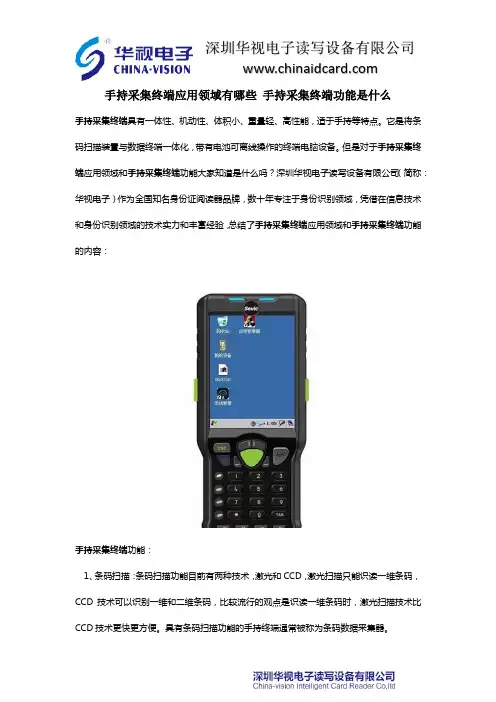
手持采集终端应用领域有哪些手持采集终端功能是什么手持采集终端具有一体性、机动性、体积小、重量轻、高性能,适于手持等特点。
它是将条码扫描装置与数据终端一体化,带有电池可离线操作的终端电脑设备。
但是对于手持采集终端应用领域和手持采集终端功能大家知道是什么吗?深圳华视电子读写设备有限公司(简称:华视电子)作为全国知名身份证阅读器品牌,数十年专注于身份识别领域,凭借在信息技术和身份识别领域的技术实力和丰富经验,总结了手持采集终端应用领域和手持采集终端功能的内容:手持采集终端功能:1、条码扫描:条码扫描功能目前有两种技术,激光和CCD,激光扫描只能识读一维条码,CCD技术可以识别一维和二维条码,比较流行的观点是识读一维条码时,激光扫描技术比CCD技术更快更方便。
具有条码扫描功能的手持终端通常被称为条码数据采集器。
2、IC卡读写:集成IC卡读写功能的手持终端通常称为IC卡手持数据终端,主要用于IC 卡证卡管理3、非接触式IC卡读写:集成非接触式IC卡读写功能的手持终端通常称为非接触式IC卡手持数据终端,主要用于非接触式IC卡管理。
4、内置信息钮:所谓信息钮就是内置的非接触式IC卡芯片,主要用于巡更。
5、指纹采集、比对:集成指纹采集模块的手持终端主要用于公安、社会保险等等6、GPS:行业应用主要用于公安,更大量的在于民用市场,为驾车人提供电子地图及定位服务手持采集终端应用领域:1、物流,典型的有烟草配送,仓库盘点、邮政配送,值得开发的有各大日用品生产制造商的终端配送、药品配送、大工厂的厂内物流、物流公司仓库到仓库的运输。
2、三表抄表,在可预见的将来,这是一个容量比较大市场。
3、移动政务,移动警务,当科技强警不仅仅只是一个口号了之后,警用设备的科技含量越来越高,特别是交警、巡警和刑警也已经开始配备移动数据设备,其中手持终端的配备,为警察提供了更强有力的执行警务的工具。
除警务外,目前卫生、城管、税务等等行政部门也开始尝试使用手持终端来规范行政业务,同时提高行政效率。


HT380K快递物流手持终端产品介绍单一、产品外观二、产品概述捷宝HT380K是专为快递物流行业精心设计的一款智能手持终端,依据快递物流行业高强度高频次使用、效率为本、复杂使用环境的特殊要求,采用高通四核平台,支持移动、电信、联通的4G全网通移动通讯,支持一维/二维条码扫描、NFC、800万像素高清摄像,在外形结构、操作系统、音量、续航和防护能力上都针对快递物流行业的需求进行开发,是一款真正满足当代快递物流行业痛点需求的手持巴枪。
HT380K以无以伦比的顶级配置和尖端设计,是快递物流行业的机皇之作。
IP65防护等级,抗摔、防水、防尘。
认证:CE、CCC三、产品特点1、高通四核,旗舰级性能高通四核处理器,主频1.2GHz,配备1GB RAM + 8GB ROM超大内存,采用针对快递物流行业深度定制开发的Android4.4操作系统,体验更加良好,具备真正的旗舰级性能,运行速度提升4-5倍。
2、4G全网通支持移动、联通、电信4G,支持TD-LTE、FDD-LTE、WCDMA、CDMA2000,GPRS、CDMA等,并支持蓝牙4.0和双频Wi-Fi,可快速传输图片、文件包等各种大文件。
3、黄金比例,瘦身设计外形更加紧凑,符合快递物流行业的使用特点的人体工学设计,屏幕与握手部分采用黄金比例分布,且握手部分采用瘦身设计,提供更加舒适的握感,方便快递员单手操作,连续多小时作业毫不疲倦。
4、康宁大猩猩阳光屏康宁大猩猩的三代玻璃,3.5英寸的高清高亮IPS液晶阳光屏,分辨率高达480*800,超宽视角,无论是室内或是户外强光环境中均清晰可视。
5、4倍的通话音量支持通话、短信功能,可当手机使用,避免快递员PDA、手机同时使用的繁琐操作。
扬声器采用大功率和完整的后音腔设计,声音宏亮、清晰,音量是普通手机的4倍,快递员在街头巷尾等各种嘈杂的环境中使用毫无压力。
6、超长使用寿命内部结构采用镁合金设计,同时采用精密模具设计,平均使用寿命高达3-5年以上。

CT40 AND CT40 HC MOBILE COMPUTERAccessories Guide1 3 45Chargers Mobile Power Supplies Scan Handles Soft Goods Accessories AC Line CordsTABLE OF CONTENTSCHARGERSCT40-CB-CNV-0CT40-CB-CNV-1CT40-CB-CNV-2CT40-CB-CNV-3CT40-NB-CNV-0Charge Base, StandardFor recharging up to fourcomputers. Kit includesdock and power supply.Power cord must be orderedseparately.Charge BaseFor recharging up to fourcomputers. Kit includes dock,power supply, and U.S. powercord.Charge BaseFor recharging up to fourcomputers. Kit includes dock,power supply, and EU powercord.Charge BaseFor recharging up to fourcomputers. Kit includes dock,power supply, and UK powercord.Net Base, StandardFor Ethernetcommunications andrecharging up to fourcomputers. Kit includesdock and power supply.Power cord must be orderedseparately.CT40-NB-CNV-1CT40-NB-CNV-2CT40-NB-CNV-3CT40-CB-PB-0CT40-NB-PB-0Net BaseFor Ethernetcommunications andrecharging up tofour computers. Kit includesdock, power supply,and U.S. power cable.Net BaseFor Ethernetcommunications andrecharging up tofour computers. Kit includesdock, power supply,and EU power cable.Net BaseFor Ethernetcommunications andrecharging up tofour computers. Kit includesdock, power supply,and UK power cable.Charge Base (use with TPUBoot)For recharging up to fourcomputers. Kit includes dockand power supply. Excludespower cord. Compatible withCT40 with TPU boot only.Net Base (use with TPUBoot)For Ethernetcommunications andrecharging up to fourcomputers. Kit includes dockand power supply. Excludespower cord. Compatible withCT40 with TPU boot only.CT40-CB-PB-1CT40-NB-PB-1CT40-CB-PB-2CT40-NB-PB-2CT40-CB-PB-3Charge Base (use with TPUBoot)For recharging up to fourcomputers. Kit includes dock,power supply, and U.S. powercord. Compatible with CT40with TPU boot only.Net Base (use with TPUBoot)For Ethernetcommunications andrecharging up to fourcomputers. Kit includes dock,power supply, and U.S. powercable. Compatible with CT40with TPU boot only.Charge Base (use with TPUBoot)For recharging up to fourcomputers. Kit includes dock,power supply, and EU powercord. Compatible with CT40with TPU boot only.Net Base (use with TPUBoot)For Ethernetcommunications andrecharging up to fourcomputers. Kit includes dock,power supply, and EU powercable. Compatible with CT40with TPU boot only.Charge Base (use with TPUBoot)For recharging up to fourcomputers. Kit includes dock,power supply, and UK powercord. Compatible with CT40with TPU boot only.CT40-NB-PB-3CT40-QBC-0CT40-QBC-1CT40-QBC-2CT40-QBC-3Net Base (use with TPUBoot)For Ethernetcommunications andrecharging up to fourcomputers. Kit includes dock,power supply, and UK powercable. Compatible with CT40with TPU boot only.QBC, StandardFor recharging up to fourbatteries. Kit includes dockand power supply. Powercord must be orderedseparately.QBCFor recharging up to fourbatteries. Kit includes dock,power supply, and U.S. powercord.QBCFor recharging up to fourbatteries. Kit includes dock,power supply, and EU powercord.QBCFor recharging up to fourbatteries. Kit includes dock,power supply, and UK powercord.CT40-HB-0CT40-HB-1CT40-HB-2CT40-HB-3CT40-EB-0Home Base, StandardKit includes dock and powersupply. Power cord mustbe ordered separately. Forrecharging computer andbattery. Supports USB clientvia USB Type B connector.Home BaseKit includes dock, powersupply, and U.S. power cord.For recharging computerand battery. SupportsUSB client via USB Type Bconnector.Home BaseKit includes dock, powersupply, and EU power cord.For recharging computerand battery. SupportsUSB client via USB Type Bconnector.Home BaseKit includes dock, powersupply, and UK power cord.For recharging computerand battery. SupportsUSB client via USB Type Bconnector.Ethernet Home Base,StandardKit includes dock andpower supply. Power cordmust be ordered separately.For recharging computer,battery, and Ethernetcommunications. SupportsUSB client via USB Type Bconnector.CT40-EB-1CT40-EB-2CT40-EB-3Ethernet Home BaseKit includes dock, powersupply, and U.S. power cord.For recharging computer,battery, and Ethernetcommunications. SupportsUSB client via USB Type Bconnector.Ethernet Home BaseKit includes dock, powersupply, and EU power cord.For recharging computer,battery, and Ethernetcommunications. SupportsUSB client via USB Type Bconnector.Kit includes dock, powersupply, and UK power cord.For recharging computer,battery, and Ethernetcommunications. SupportsUSB client via USB Type Bconnector.CT40-DB-0CT40-DB-1CT40-DB-2CT40-DB-3Display Dock, StandardFor connection with anexternal display, and extendsI/O for HDMI, Ethernetcommunications, and threeUSB ports. Kit includesdisplay base and powersupply. Must order powercord separately.Display DockFor connection with anexternal display, and extendsI/O for HDMI, Ethernetcommunications, and threeUSB ports. Kit includesdisplay base, power supply,and U.S. power cord.Display DockFor connection with anexternal display, and extendsI/O for HDMI, Ethernetcommunications, and threeUSB ports. Kit includesdisplay base, power supply,and EU power cord.Display DockFor connection with anexternal display, and extendsI/O for HDMI, Ethernetcommunications, and threeUSB ports. Kit includesdisplay base, power supply,and UK power cord.MOBILECT40-SN-USB-0CT40-VD-0CT40-CIGR-050138169-001805-638-001Snap-On Adapter withTethered USB Cable toSupport USB ClientProvides tethered USB clientconnectivity. Compatiblewith hand strap, battery pack,and scan handle. Chargesmobile computer batteryin four hours or less. Kitincludes snap-on adapter.Optional 50130570-001(5 V/2 A) USB power walladapter sold separately.Vehicle DockVehicle dock with hard-wired3-pin power cable.Cigarette Snap-On AdapterCigarette lighter adapterwith USB SKT.Cigarette LighterPower Adapter CableCigarette lighter poweradapter, 1.8 mm (0.07 in).RAM MountRequired for vehicle dockor vehicle holder. Consistsof one 12.07 cm (4.75 in)adjustable pivot arm with two3.8 cm (1.5 in) stainless steelballs and assembly hardware.Requires customer-suppliedhardware to secure mount tovehicle.CT40-HDST-35MM CT40-CVT-25MMPTT HeadsetEnterprise headset with PTTfunction, 3.5 mm (0.14 in), 1.8m (5.9 ft) length.Audio Cable3.5 mm (0.14 in) plug to2.5 mm socket adapter wire.POWER SUPPLIES318-055-011318-055-01550121666-00150121667-00150130570-001Spare Battery Pack CT40 Battery Pack, 4040 mAh, for use with CT40 configurations with plastic battery latch button (last two digits in part number begin with 0: CT40-L*N-xxxxx 0x).Spare Battery Pack CT40 Battery Pack, 4040 mAh, for use with CT40 configurations with metal battery latch button (last two digits in part number begin with A or B :CT40-L0N-xxxxx A x or CT40-L1N-xxxxx B x).Desktop Power Supply A 36 W power supply for use with Ethernet home base, charge-only home base, and quad battery charger. Requires country-specific line cord to be ordered separately.Quad Base Power Supply A 84 W power supply for use with four-bay charging base and four-bay net base. Requires country-specific line cord to be ordered separately.Power Plug Adapter Kit USB power adapter (5 V, 2 A) kit for snap-on adapter. Includes EU, UK, U.S., and IN plugs.SCAN HANDLESCT40-SH-DCCT40-SH-PBScan Handle, Compatible with Charging Dock Snaps easily on or off the mobile computer. Compatible with charging docks, hand strap, and snap-on adapter.Scan Handle and TPU Boot Kit, CT40 scan handle, and TPU boot, compatible with charge base CT40-CB-PB-0/1/2/3 and net base CT40-NB-PB-0/1/2/3.SOFT GOODS825-238-001CT40-PB-00CT40-RB-00825-237-001HolsterHolster suitable for use with CT40, CT50, and CT60.TPU BootCT40 TPU boot, compatible with charge base CT40-CB-PB-0/1/2/3 and net base CT40-NB-PB-0/1/2/3.Rubber BootBlack rubber protective boot for CT40.PouchPouch suitable for use with CT40, CT50, and CT60.ACCESSORIESCT40-HS-3PK CT40-HS-HCCT40-SP-1PK CT40-QL-00Kit, Hand Strap (3/pk)Kit of three replacement hand straps for CT40.Health Care Hand Strap (3/pk)Built with disinfectant-ready material. Can be cleaned by approved disinfectant agents.Screen Protector (1/pk)One self-adhesive screen protector.Quad Lock Case CT40 quad lock case to mount CT40 on Zebra RFD8500 RFID sled with quad lock.856-065-004856-065-005856-065-006856-065-007Industrial-Grade Micro-SD Card*Micro-SD card, 1 GB, AF1GUDI, RoHSIndustrial-Grade Micro-SD Card*Micro-SD card, 2 GB, AF2GUDI, RoHSIndustrial-Grade Micro-SD Card*Micro-SD card, 4 GB, AF4GUDI, RoHSIndustrial-Grade Micro-SD Card*Micro-SD card, 8 GB, AF8GUDI, RoHS* Micro-SD cards are required when databases are stored on the device. The database should be stored on the SD card.AC LINE CORDS50127245-00150117501-00150117503-00177900506E 77900507E Power Cord – India Power cord, India, 1.5 m (4.9 ft)Power Cord – Australia Power cord, Australia, 2.5 m (8.2 ft)Power Cord – CB Power cord, Argentina, Isled CBPower Cord – U.S.Power cord, U.S., IEC320-C13, 1.85 m (6.07 ft)Power Cord – UK Power cord, UK, IEC320-C13, 2.5 m (8.2 ft)77900508E 19-1980719-19726Power Cord – EU Power cord, Europe, IEC320-C13, 2.5 m (8.2 ft)Power Cord – China Cable, China cord set (CCC), 2.5 m (8.2 ft)Power Cord – U.S.Cable, power cord/IEC, U.S., 2.5 m (8.2 ft)For more informationHoneywell Safety and Productivity Solutions 9680 Old Bailes RoadFort Mill, SC 29707 CT40 and CT40 HC Accessories Guide | Rev F | 10/19© 2019 Honeywell International Inc.。

[广州捷宝电子科技股份有限公司] | 股票代码:839165 |RFID规格愈趋多样 6种适合导入的应用领域介绍摘要:生产线若能减少人力投入比重、增加RFID技术自动化配置,有助提升产线效率、强化安全性与减少工伤风险。
至于在众多RFID技术中何种最佳的问题,实际上没有绝对的答案,因基于不同应用的需求,各有最适合的RFID技术可选择,如需多长讯息接收距离、是否需要在RFID卷标内建内存写入大量信息、要在潮湿环境使用RFID标签等。
如何做出最佳选择,将取决不同需求者使用情境、条件与需求。
生产线若能减少人力投入比重、增加RFID技术自动化配置,有助提升产线效率、强化安全性与减少工伤风险。
至于在众多RFID技术中何种最佳的问题,实际上没有绝对的答案,因基于不同应用的需求,各有最适合的RFID技术可选择,如需多长讯息接收距离、是否需要在RFID标签内建内存写入大量信息、要在潮湿环境使用RFID标签等。
如何做出最佳选择,将取决不同需求者使用情境、条件与需求。
据Control Design网站报导,仅几年前全球RFID技术选择数量仍有限,如今不仅更多元化、RFID 标签愈做愈小,效能却也愈来愈好、并可应用至更多严苛使用环境,如可直接黏在金属上,以及可耐高温最多达摄氏250度;若采用极高频(UHF)被动式RFID技术,读取速度甚至可达400tags/s。
如今RFID技术不再只是单独存在的技术,为RFID标签加入传感器更成为如今普遍做法,并协助业者执行定性追踪任务,如下即介绍几种RFID技术适合导入的应用领域。
如在工具机领域,部分制程的自动化有助减少人为失误及工伤事故,这可能会导致机台系统停止运转,因此随着愈来愈多机台导入计算机数值控制工具机(CNC),若导入RFID标签技术至该自动化制程中,将有助轻易克服这些问题。
一般用于生产零组件的机台,在选择切削刀具及管理切削刀具使用上必须予以自动化,才有助减少人为操作的损失。

SA808 INSTRUCTION MANUAL We’ll Make It Stress-FreeIf you have any questions along the way, just give us a call.1-800-359-5520. We’re ready to help!Scan for easy install video/4472Before getting started, let’s make sure this product is perfect for you!WARNING:This product contains small items that could be a choking hazard if swallowed.Before starting assembly, verify all parts are included and undamaged. If any parts are missing or damaged, do not return the damaged itemto your dealer; contact Customer Service. Never use damaged parts!353. Use a drywall saw or similar tool to cut the drywall where marked. Remove cut section of drywall.1. Break out the sections of the housing 02 that are required to install the power and cable outlets that are needed.2. Thread the elastic-velcro strap into the housing 02.681.To use the ECO-Mini (purchased separately) in the SA808, first remove feet.2. Fit the ECO-Mini into the ECO-Mini bracket 05 supplied with the SA808.3. Use two of the screws from the feet to secure the ECO-Mini in the bracket 05.4. Slide the ECO-Mini and bracket 05 into the top of the housing 02. Lock the bracket 05 into the housing 02 by sliding it towards thecorner until you feel it catch.5. Use the elastic-velcro strap 03 to attach components to the housing 02.6. Power the ECO-Mini with the power cord supplied with the ECO-Mini.The SA808 can be installed behind most large wall plates of wall mounts or underneath or above most small wall plates. To access the SA808 after installation, disconnect all cables and wires from the TV, then either slide or remove the arm or TV mount from the wall plate. IMPORTANT: Check your TV owner’s manual to see if there are any special requirements for mounting or removing your TV.12 5.83 in.[148.0 mm]7.80 in.[198.1 mm]13.80 in.[350.5 mm]11.80 in.[299.8 mm]4.00 in.[101.6 mm] 125°13Before getting started, let’s make sure this product is perfect for you!- see page 21. Will your accessories weigh more than 50 lb (22.7 kg)?No — Perfect!Yes — This product is NOT compatible. Visit or call 1-800-359-5520 [UK: 0800 056 2853] to fi nd a compatible product.2. What is your wall made of?3. Do you have all of the tools needed?4. Ready to begin?Please read through these instructions completely to be sure you’re comfortable with this easy install process.If you do not understand these instructions or have doubts about the safety of the installation, assembly or use of this product, contact Customer Service at 1-800-359-5520 [UK: 0800 056 2853].CAUTION: Avoid potential personal injuries and property damage!●Do not use this product for any purpose not explicitly specifi ed by manufacturer.●Manufacturer is not responsible for damage or injury caused by incorrect assembly or use.Supplied Parts- see page 3WARNING:This product contains small items that could be a choking hazard if swallowed.Before starting assembly, verify all parts are included and undamaged. If any parts are missing or damaged, do not return the damaged item to your dealer; contact Customer Service. Never use damaged parts!STEP 1 Cut Hole for Housing- see page 4CAUTION:Avoid potential personal injuries and property damage!●Minimum drywall thickness 1/2 in. (13 mm).●Box must be mounted between studs that are at least 16 in. (406 mm) apart.141. Locate the studs using an edge-to-edge stud finder. Verify the edges of the studs using an awl or thin nail. Mark the inner edges of thestuds with pencil.2. The open area on the left of the template 01 should line up the the inner edge of the left stud. This will allow space for the placement ofa power box on the right side of the housing 02. Level the template 01 and use a pencil to mark the open area of the template 01.3. Use a drywall saw or similar tool to cut the drywall where marked. Remove cut section of drywall.WARNING!Electric Shock Hazard! Avoid potential serious injuries or death. Ensure there are no electrical wires behind the wall before cutting or drilling into the surface.WARNING!Explosion and Fire Hazard! Avoid potential serious injuries or death. Ensure there are no gas lines behind the wall before cutting or drilling into the surface.4. Install wires and cables.2. Thread the elastic-velcro strap into the housing 02.3. Mount a power outlet (if needed) to the housing 02. Slide cables and additional wires through the hole in the bottom of the housing 02and the rubber cable grommet 04. Fit the cable grommet 04 into the hole.4. Using a screwdriver, turn the screws in the corners of the housing 02 . These will raise the locking tabs in the rear of the housing 02 tosecure it to the wall. Tighten only until secure. Do not over-tighten screws.STEP 3 Install Components- see page 8ECO-Mini (purchased separately) with the SA808 - Optional1. To use the ECO-Mini (purchased separately) in the SA808, first remove feet.2. Fit the ECO-Mini into the ECO-Mini bracket 05 supplied with the SA808.153. Use two of the screws from the feet to secure the ECO-Mini in the bracket 05.4. Slide the ECO-Mini and bracket 05 into the top of the housing 02. Lock the bracket 05 into the housing 02 by sliding it towards thecorner until you feel it catch.5. Use the elastic-velcro strap 03 to attach components to the housing 02.6. Power the ECO-Mini with the power cord supplied with the ECO-Mini.Positioning- see page 11The SA808 can be installed behind most large wall plates of wall mounts or underneath or above most small wall plates. To access the SA808 after installation, disconnect all cables and wires from the TV, then either slide or remove the arm or TV mount from the wall plate.IMPORTANT: Check your TV owner’s manual to see if there are any special requirements for mounting or removing your TV. Dimensions- see page 12161718Milestone AV Technologies and its affi liated corporations and subsidiaries (collectively, “Milestone”), intend to make this manual accurate and complete. However, Milestone makes no claim that the information contained herein covers all details, conditions, or variations. Nor does it provide for every possible contingency in connection with the installation or use of this product. The information contained in this document is subject to change without notice or obligation of any kind. Milestone makes no representation of warranty, expressed or implied, regarding the information contained herein. Milestone assumes no responsibility for accuracy, completeness or suffi ciency of the information contained in this document.©2013 Milestone AV Technologies, a Duchossois Group Company. All rights reserved. Sanus is a division of Milestone.All other brand names or marks are used for identifi cation purposes and are trademarks of their respective owners.Thank you for choosing Sanus!Please take a moment to let us know how we did:SANUS• 6436 City West Parkway • Eden Prairie, MN 55344 USACall us: 800-359-5520UK: 0800 056 28536901-002209 00Emailus:**************Find us on the web: 。

1224 East Warner Ave, Santa Ana, CA 92705 Tel: 1-714-545-5511 TS-H800, Rev: F, Date: 22 Jan 16, DCR: 16-0054H800Compact Universal Straight Pulling Headfor the G800 riveter INSTRUCTION SHEET , Page 1 of 2Table 1: Nose Piece Selection GuideDIMENSIONAL DATA (see Fig. 1)∙ Weight- 0.15 Lbs.Choice of Riveters ∙Use with the G-800 hand riveter:MOUNTING INSTRUCTIONS (see Fig 2)∙ Depress the pressure release button of the riveter and make sure the piston is fully returned.∙ Place the stem stop & spring inside of the riveter piston∙ Thread and tighten the collet assembly onto the riveter piston ∙Thread in the sleeve assy and lock it in by tightening the Jam Nut.JAW ADJUSTMENTThe jaws have to be adjusted to allow front ejection of the spent stem ∙ Push the fastener all the way through the front nose piece.∙ While sliding the stem back and forth inside the nose piece, thread the sleeve assembly in until the stem is released.∙ Lock the sleeve assembly in position by tightening the Jam Nut.OPERATING INSTRUCTIONSPrior to tool operation make sure that:∙ Pulling Head is correctly mounted on the riveter and jaws are properly adjusted∙ A proper nose-piece in good working condition is used.During Operation:∙ Inspect the active area of the nosepiece regularly.∙ Keep the tool clean, especially the nosepiece and jaws; pay special attention when sealants and adhesives are used. ∙ If stem slippage occurs, clean or replace the jaws.∙ Re-adjust Jaws if the stem does not front eject properly.Fig. 1. Dimensional DataFig. 2 MountingFig. 3782-3E ExtendedNosepiece1224 East Warner Ave, Santa Ana, CA 92705 Tel: 1-714-545-5511 TS-H800, Rev: F, Date: 22 Jan 16, DCR: 16-0054H800Compact Universal Straight Pulling Head for the G800 riveterINSTRUCTION SHEET , Page 2 of 2PARTS LISTNote: Items 1, 5 & 6 are fastener type and size dependent. See Table 1 for fastener capability and component selection.PREVENTATIVE MAINTENANCE∙ Clean and inspect the nosepiece, jaws, collet & spring every 1000 installations or whenever a failure occurs; replace spring and jaws if worn.∙ Lubricate outside configuration of the Jaws with Lubriplate® or similar light grease. ∙ Inspect regularly and keep active area clean and in good working condition. ∙ Replace worn or broken components.∙ When re-assembling align the jaws with the jaw follower as shown in the exploded view (items 5 and 6); pay attention to the position and orientation of the Stem Stop (item 8).∙ Use Loctite ® 242 (removable) on all threaded components except as shown.LOCTITE® is a registered trademark of Henkel Corporation.LUBRIPLATE® is a registered trademark of Fiske Brothers Refining Co.Do not apply Loctite ® on these threadsITEM No1782-456Nosepiece (see table 1)12800-033Sleeve 13671A16Jam Nut 14753A13A Collet15701B18Jaw Set (see table 1)16753A14A Jaw Follower (see table 1)17800-032Drawbar 18753A15Stem Stop19P-1483Compression Spring1PART NUMBER DESCRIPTION QTY.。
User guideStereo Bluetooth® HeadsetContents Introduction (3)Function overview (3)Hardware overview (3)Basics (5)Charging the battery (5)Battery status (5)Turning the headset on and off (5)Adjusting the volume (5)Resetting the headset (6)Wearing instruction (6)Getting started (7)Preparing to use your headset with a Bluetooth® device (7)Using your headset (8)Using your headset to handle phone calls (8)Using your headset to listen to music (8)Using your headset with two devices simultaneously (8)Troubleshooting (10)I cannot answer a second call (10)Music from another device does not play in the headset (10)The headset turns off automatically (10)No connection between headset and other device (10)Unexpected behaviour (10)Legal information (11)Declaration of Conformity (12)IntroductionFunction overviewYour Stereo Bluetooth® Headset SBH80 is designed to make life more convenient when you're on the go. You can use it together with an Android™ powered device such as a phone or tablet, or with a Bluetooth® compatible device such as a non-Android phone, a computer or a music player. When paired with a compatible device, you can use your headset to control incoming and outgoing phone calls or to listen to music.Hardware overview1NFC detection area Touch other devices to this area during NFC pairing.2Micro USB port Insert the cable for charging the battery.3Notification light Flashing red light: battery level is between 0% and 4%.Yellow light: battery level is between 5% and 29%.Green light: battery level is between 30% and 100%.Flashing cyan-coloured light: headset is in pairing mode.Flashing purple light: a call is coming in.4Power key Press and hold down to turn the headset on or off.When the headset is on, briefly press to show anotification light indicating battery level.5Next key Press to play the next track.6Play /Pause key Press to play or pause the current track.7Previous key Press to play the previous track.8Antenna9Volume down key Press to turn down the volume.10Call key Press to answer incoming calls.Press and hold down to reject incoming calls. 11Volume up key Press to turn up the volume.BasicsCharging the batteryBefore using the Stereo Bluetooth® Headset SBH80 for the first time, you need to charge the headset for approximately 2.5 hours. Sony chargers are recommended.To charge your headset1Plug one end of the USB cable into the charger or into the USB port of a computer.2Plug the other end of the cable into the Micro USB port of your Stereo Bluetooth® Headset SBH80 device.Battery statusYou can view an estimate of how much time is left before the battery of yourheadset runs out after you have connected it with a compatible device. You can view the battery status information from the Notification panel of the connected device, or from the Smart Connect application installed on the connected device.The Smart Connect application works on Android™ devices, and it is pre-installed on all Android™ devices from Sony Mobile at purchase. Make sure you haveinstalled the latest version of Smart Connect application on your Android™ device from Google Play™.To view the estimated battery time from the Notification panel•Drag the status bar downwards, the estimated battery time is shown on the Notification panel.To view the estimated battery time from the Smart Connect application1From the Home screen of your Android™ device, tap , then find and tap Smart Connect.2Tap Devices > SBH80.Turning the headset on and offTo turn on the headset•Press and hold down until the headset vibrates and the notification light turns green.To turn off the headset•Press and hold down until the headset vibrates.Adjusting the volumeTo change the call or music volume•During a call, or when listening to music, press or .Resetting the headsetReset the headset if it behaves unexpectedly. Resetting the headset removes all information about paired devices.To reset the headset1Turn off the headset, then connect the charger so that the headset starts to charge.2Press and hold down until the headset vibrates briefly.Wearing instructionTo get the best performance from your headset when using it outdoors, it isrecommended that you carry the device that you have paired with the headset on the same side of your body as the antenna of the headset unit.Getting startedPreparing to use your headset with a Bluetooth® deviceBefore you can start using your headset with a Bluetooth® device, you need to pair the headset with the Bluetooth® device manually using Bluetooth® orautomatically using NFC.To manually pair your headset with a Bluetooth® device1Bluetooth® device: Make sure the Bluetooth® function is turned on.2Turn off your headset.3Headset: Press and hold down until the headset vibrates and a cyan-coloured notification light flashes continuously.4Bluetooth® device: Scan for Bluetooth® devices, then select Stereo Bluetooth® Headset SBH80 in the list of available devices.5Bluetooth® device: Follow the pairing instructions that appear on the screen.To automatically pair your headset with a Bluetooth® device1Bluetooth® device: Make sure that the NFC function is turned on and that the screen is active and unlocked.2Headset: Press and hold down until the headset vibrates and a cyan-coloured notification light flashes continuously.3Place the Bluetooth® device over your headset so that the NFC detection area of each device touches the other.4Bluetooth® device: Follow the pairing instructions that appear.The device used in this illustration is for illustration purposes only and may not accurately depict the actual device used.Using your headsetUsing your headset to handle phone callsUse the headset to handle incoming calls, for example, to answer or reject a call.To answer a call with the headset•When you hear an incoming call signal, press .To end a call•During an ongoing call, press .To reject a call•When you hear an incoming call signal, press and hold down .To answer a second call•When you hear an incoming call signal during an ongoing call, press . The ongoing call is put on hold.You can also press or to switch to another call and put the current call on hold.To reject a second call•When you hear an incoming call signal during an ongoing call, press and hold down .To mute and unmute the microphone during a call•Press and hold down to mute the microphone. To unmute the microphone, press and hold down again.Using your headset to listen to musicYou can listen to music from your phone or another Bluetooth® compatible device using your headset.To listen to music1Open the music player application in your device and select a track that you want to listen to.2Press to play the track. To pause the track, press again.To move between tracks•Press or .To fast forward or rewind a music track•Press and hold down or to fast forward or rewind until you reach thedesired position.Using your headset with two devices simultaneouslyYour headset has two different connection modes: Multipoint mode andSinglepoint mode. Multipoint mode helps you manage two connections at the same time. For example, if you connect your headset with two phones, you can receive calls from both phones without having to disconnect and reconnect.Multipoint mode is enabled by default. If you stop using one of two connected devices, you should switch to Singlepoint mode manually.In Multipoint mode, the headset remembers both paired devices. You canreconnect previously paired devices easily by manually switching back toMultipoint mode from Singlepoint mode. A previously paired device can then be detected automatically.You can only connect to a maximum of two devices in Multipoint mode. If you pair the headset with a third device, the first paired device gets disconnected.To manually pair your headset with a second device•After manually pairing the first device with your headset, repeat the same instruction steps that describe how to manually pair your headset withanother device.To automatically pair your headset with a second device•After pairing the first device with your headset automatically, repeat the same instruction steps that describe how to automatically pair your headset with another device.To switch between Multipoint mode and Singlepoint mode1Make sure that the headset is turned off.2Put the headphones in your ears.3To enter Multipoint mode, press and hold down the volume up key while turning on the headset. After Multipoint mode is activated, you will hear two beeps.4To enter Singlepoint mode, press and hold down the volume down key while turning on the headset. After Singlepoint mode is activated, you will hearone beep.In order to connect to both paired devices in Multipoint mode, you need to restart the headset.TroubleshootingI cannot answer a second call•Make sure that your calling device supports the Bluetooth® headset profile.•Make sure that the correct calling device is selected.Music from another device does not play in the headset •Make sure that the music-playing device is paired with the headset.•Restart the music player application on the music-playing device.•Make sure that the correct music source is selected.The headset turns off automatically•If the headset beeps several times shortly before turning off, the battery level is low. Charge the battery.No connection between headset and other device•Make sure that the headset is charged and within range of the device that you want to connect to. A maximum distance of 10 metres (33 feet), with no solid objects in between, is recommended.•Disable the Bluetooth® function in the other device so that all connections are closed, then re-enable the Bluetooth® function and pair the headset with the device again.Unexpected behaviour•Reset the headset.Legal informationSony SBH80Prior to use, please read the Important information leaflet separately provided.This User guide is published by Sony Mobile Communications AB or its local affiliated company, without any warranty. Improvements and changes to this User guide necessitated by typographical errors, inaccuracies of current information, or improvements to programs and/or equipment, may be made by Sony Mobile Communications AB at any time and without notice. Such changes will, however, be incorporated into new editions of this User guide.All rights reserved.©2014 Sony Mobile Communications AB.Interoperability and compatibility among Bluetooth® devices varies. Device generally supports products utilizing Bluetooth spec. 1.2 or higher, and Headset or Handsfree profile.Sony is the trademark or registered trademark of Sony Corporation. Bluetooth is the trademark of the Bluetooth (SIG) Inc. and is used under license. All other marks are the property of their respective owners. All rights reserved.All product and company names mentioned herein are the trademarks or registered trademarks of their respective owners. Any rights not expressly granted herein are reserved. All other trademarks are property of their respective owners.Visit for more information.All illustrations are for illustration only and may not accurately depict the actual accessory.Declaration of ConformityWe, Sony Mobile Communications AB ofNya VattentornetSE-221 88 Lund, Swedendeclare under our sole responsibility that our productSony type RD-0040and in combination with our accessories, to which this declaration relates is in conformity with the appropriate standards EN 300 328:V1.7.1, EN 301 489-3:V1.6.1, EN 301 489-7:V1.3.1, EN 301 489-17:V2.2.1 and EN 60 950-1:2006+A11:2009+A1:2010+A12:2011 following the provisions of, Radio Equipment and Telecommunication Terminal Equipment directive 1999/5/EC.Lund, January 2014Pär Thuresson,Quality Officer, SVP, Quality & Customer ServicesFCC StatementThis device complies with Part 15 of the FCC rules. Operation is subject to the following two conditions: (1)This device may not cause harmful interference, and (2) This device must accept any interference received,including interference that may cause undesired operation.Any change or modification not expressly approved by Sony may void the user's authority to operate theequipment.This equipment has been tested and found to comply with the limits for a Class B digital device, pursuant toPart 15 of the FCC Rules. These limits are designed to provide reasonable protection against harmfulinterference in a residential installation. This equipment generates, uses and can radiate radio frequencyenergy and, if not installed and used in accordance with the instructions, may cause harmful interference toradio communications. However, there is no guarantee that interference will not occur in a particularinstallation.If this equipment does cause harmful interference to radio or television reception, which can be determinedby turning the equipment off and on, the user is encouraged to try to correct the interference by one ormore of the following measures:•Reorient or relocate the receiving antenna.•Increase the separation between the equipment and receiver.•Connect the equipment into an outlet on a circuit different from that to which the receiver is connected.•Consult the dealer or an experienced radio/TV technician for help.Industry Canada StatementThis device complies with RSS-210 of Industry Canada.Operation is subject to the following two conditions: (1) this device may not cause interference, and (2) thisdevice must accept any interference, including interference that may cause undesired operation of thedevice.This Class B digital apparatus complies with Canadian ICES-003.Cet appareil numérique de la classe B est conforme à la norme NMB-003 du Canada.Avis d’industrie CanadaLe présent appareil est conforme aux CNR d'Industrie Canada applicables aux appareils radio exempts delicence.L'exploitation est autorisée aux deux conditions suivantes: (1) l'appareil ne doit pas produire de brouillage,et, and (2) l'utilisateur de l'appareil doit accepter tout brouillage radioélectrique subi, même si le brouillageest susceptible d'en compromettre le fonctionnement.Cet appareil numérique de la classe B est conforme à la norme NMB-003 du Canada.Les dispositifs fonctionnant dans la bande 5150-5250 MHz sont réservés uniquement pour une utilisation àl’intérieur afin de réduire les risques de brouillage préjudiciable aux systèmes de satellites mobiles utilisantles mêmes canaux. Le gain maximal d’antenne permis pour les dispositifs utilisant les bandes 5250-5350MHz et 5470-5725 MHz doit se conformer à la limite de p.i.r.e. Le gain maximal d’antenne permis (pour lesdispositifs utilisant la bande 5725-5825 MHz) doit se conformer à la limite de p.i.r.e. spécifiée pourl’exploitation point à point et non point à point, selon le cas. De plus, les utilisateurs devraient aussi êtreavisés que les utilisateurs de radars de haute puissance sont désignés utilisateurs principaux (c.-à-d., qu’ilsont la priorité) pour les bandes 5 250-5 350 MHz et 5 650-5 850 MHz et que ces radars pourraient causer dubrouillage et/ou des dommages aux dispositifs LAN-EL.。
兰德HT-2800 掌上电脑用户手册1.0版2001.1.18兰德智科电子有限公司/前言多谢您购买本公司的产品。
为了使您更好的使用本机,敬请仔细阅读本机的使用手册,并存放于方便的位置,以供日后参考之用。
对于因操作不当造成机内资料的损失,本公司概不负责;因机内资料泄漏给第三者而造成的损失,本公司亦不负责。
本公司将不断改善提高产品的质量,所以版本会时有更新,而说明书未能及时修正之处,敬请见谅。
目录第 1 章HT-2800简介 (1)1.1HT-2800外观 (2)1.2HT-2800性能一览表 (3)1.3HT-2800特性介绍 (4)1.3.1DOS兼容的HTOS操作系统 (4)1.3.2完善的仿真开发环境 (4)1.3.3完善的电源管理 (4)1.3.4较大的线形内存 (5)1.3.5安全的、大容量的外存储器 (5)1.3.6先进的文件管理机制 (5)1.3.7完善的通讯机制 (6)1.3.8灵活的液晶显示方式 (6)1.3.9不可多得的多任务特性 (7)1.3.10100%关机现场保护 (7)1.3.11方便的用户升级 (7)1.3.12通用的IC卡接口 (7)1.3.13一体化的可充电电池组 (8)1.4其他参考书籍 (8)第 2 章入门实例 (9)2.1DOS环境下的操作实例 (9)2.1.1安装用户盘 (9)2.1.2进入文件通讯服务器状态 (9)2.1.3下装“字母谜”示例程序 (10)2.1.4运行“字母谜”示例程序 (11)2.1.5退出“字母谜”示例程序 (12)2.1.6下装并运行HTBase示例程序 (12)2.2W INDOWS环境下的操作实例 (13)2.2.1安装用户盘 (13)2.2.2进入文件通讯服务器状态 (13)2.2.3下装“字母迷”示例程序 (13)2.2.4运行“字母迷”示例程序 (14)2.2.5退出“字母迷”示例程序 (14)2.2.6下装并运行HTBase示例程序 (14)第 3 章HT-2800用户盘 (15)3.1安装用户盘 (15)3.1.1DOS环境安装用户盘 (15)3.1.2Windows环境安装用户盘 (15)3.1.3用户盘文件详细介绍 (16)第 4 章HT-2800基本操作 (18)4.1开关机 (18)4.1.1开机 (18)4.1.2关机 (19)4.2键盘使用 (19)4.3HT-2800主控台使用 (24)4.3.1执行程序 (26)4.3.2文件管理的使用 (26)4.3.3计算器的使用 (28)4.3.4文件通讯服务器 (29)4.3.5通讯设置 (31)4.3.6系统设置 (31)4.3.7系统信息 (34)4.4HT-2800电池及充电器的使用 (37)4.4.1主电池的使用及充电 (37)4.4.2备份电池的使用及充电 (37)4.4.3充电器的使用说明 (37)4.4.4电池使用过程中的注意事项 (38)第 5 章HT-2800的文件通讯 (39)5.1与HT-2800连接 (39)5.2DOS文件通讯程序 (39)5.2.1EXFPUT.EXE 发送文件 (40)5.2.2EXFGET.EXE 获取文件 (41)5.2.3EXFDEL.EXE 删除对方文件 (41)5.2.4CP4PC.EXE 通讯核心驻留程序 (42)5.2.5HTLIST.EXE 列目录 (43)5.2.6HTCOMM.EXE 通讯的集成环境 (43)5.2.7EXFSERV.EXE 文件通讯服务器 (46)5.3W IN9X/W IN NT4.0/W IN 2000通讯程序 (47)5.4W IN31通讯程序 (48)5.5两台HT-2800间传送文件 (48)5.6利用文件通讯服务器修改HT-2800的时间 (49)第 6 章HT-2800使用深入 (50)6.1HT-2800的多任务机制 (50)6.2HT-2800的实屏与虚屏 (51)6.3PC机上的液晶仿真环境 (52)6.4HT-2800上的文件系统 (53)6.5系统配置文件和自动批命令文件 (54)6.5.1HTCONFIG.SYS (54)6.5.2HTAUTO.BAT (56)6.6重新启动和恢复到出厂状态 (57)6.7忘记主控密码怎么办 (58)第7 章固化、升级用户的程序和文件 (59)7.1编制ROM固化文件 (59)7.2HT-2800固化(升级)程序/文件方法 (60)7.3用户程序/文件固化可用空间 (63)第8 章常见问题解答 (64)8.1用户一般关心的问题 (64)8.2通讯问题 (66)8.3电池使用问题 (68)8.4程序开发问题 (68)8.5其它问题 (69)附录一HT-2800通讯口定义 (71)附录二HT-2800选件 (72)HT-2800外观第 1 章HT-2800简介HT-2800掌上电脑主要适用于在各种流动性强的工作领域中进行数据采集和现场数据分析处理的工作。
product information serving the gas industry worldwide2Safety relief valve HON 832Application, characteristics, technical dataapplication• As leak gas SRV with internal vent connection (function class B in accordance with DIN 33821)• V ariant as proportional SRV with autonomous vent connection (function class A in accordancewith DIN 33821)• For systems in municipal applications and industrial operations• L eak gas SRV type “B”, e. g. for blowing off gas leakages downstream of gas pressure regulators to prevent the SSV from tripping by accident in the event of gas pressure regulator leaks due to consumer zero droop • C an be used for gases in accordance with DVGW Worksheet G 260 and neutral, non-aggressive gases; other gases on requestcharacteristics• Simple, compact design• Position-independent installation• Safe operation• High actuating accuracy• Integrated vent line for use as leak gas SRV (type “B“)Device-specific operating instructions, maintenance instructions, spare parts drawings, and spare parts lists are provided in the brochure “Operating and Maintenance Manual / Spare Parts List 832.20”.3Safety relief valve HON 832Application, properties, technical data*) = vertical cross sectionSafety relief valve HON 832Dimensions4E 12E 205Safety relief valve HON 832A safety relief valve (SRV) has the task of autonomously releasing a gas flow from a pressurised line, as soon as the pressure in the system to be safeguarded reaches the set response pressure through increasing increments. The SRV closes again when the pressure in the system to be safeguarded drops below the closing pressure.The Safety relief valve HON 832 is a directly acting device (works without auxiliary energy) with spring loading.The safety device is designed in two variants: as leak gas SRV and as proportional SRV.When the device is used as a leak gas SRV (type “B” in accordance with 33821) the spring space is vented in-ternally via the vent line. When the device is used as a proportional SRV (type “A” in accordance with DIN 33821) on the spring housing a connection piece is arranged for the autonomous vent line to the free atmosphere.The pressure to be monitored on the inlet side (actual value) is switched internally and compared with thes pecified force of the adjustable setpoint spring. If the pressure in the system to be safeguarded exceeds the set response pressure, the main valve opens and allows the excess gas to flow off via the outlet line. The safety relief valve closes again automatically when the pressure of the system to be safeguarded drops below the response pressure of the SRV.The lateral forces that occur due to the setpoint spring are dissipated directly to the housing via the guide bush. This ensures a high reproducible response accuracy.The valve piston of the main valve is force-relieved through a control spring. Through this measure the valve trim is protected against impermissible stress. The measuring diaphragm is formed as a bead-moulded diaphragm. This means that the high actuating accuracy of the device is also ensured at lower operating temperatures.Structure and mode of operation6Safety relief valve HON 832Structure and mode of operationInlet lineInternal venting Measuring diaphragmSetpoint spring Setpoint adjuster Cover capOutlet line Valve seat Valve disc with sealing ringSpindle bushAutonomous vent connection for proportional SRV (Type “A” in accordancewith DIN 33821)Note: internal venting sealedleak gas quantity SrV (type “B” it accordance with din 33821)7hon 832 - B - e12 / e20 - 1Safety relief valve HON 832device description (example)Device designationHON 832.002017-01© 2017 Honeywell International Inc.For More Information To learn more about Honeywell’s Advanced Gas Solutions, visit or contact your Honeywell account manager GERMANYHoneywell Process Solutions Honeywell Gas Technologies GmbH Osterholzstrasse 4534123 Kassel, Deutschland Tel: +49 (0)561 5007-0Fax: +49 (0)561 5007-107。