基于模糊控制的高精度数控恒流源设计
- 格式:pdf
- 大小:1.20 MB
- 文档页数:2

恒流源在高精度数字多用表中的设计与实现毕业论文外文翻译Design and Implementation of Constant Current Source in High Precision Digital MultimetersAbstract:As an essential component in high precision digital multimeters, the constant current source (CCS) plays a crucial role in ensuring the accuracy of the measurement results. In this paper, we introduce the design and implementation of a CCS in a high precision digital multimeter. Firstly, we analyze the working principle of different types of CCS and compare their advantages and disadvantages. Then, we propose a new design of CCS based on a current-to-voltage converter and a feedback loop. The implementation of CCS is realized by integrating the proposed design with the existing measurement circuitry, and the performance of the CCS is evaluated through several measurements. The results show that our design achieves high linearity, low temperature drift, and good stability.Introduction:Digital multimeters (DMMs) are widely used in various fields due to their high precision, fast measurement speed, and easy operation. The accuracy of the measurement results depends on the quality of the measurement circuitry, especially the constant current source (CCS), which provides a stable and precise current for the measurement. The CCS should have high linearity, low temperature drift, and good stability to ensure the accuracy of the measurement results. In this paper, we present the design and implementation of a CCS in a high precision DMM, which meets the requirements of accuracy, stability, and reliability.Analysis of CCS:The CCS is an important part of the measurement circuitry in DMMs. There are several types of CCS, including the resistor-based CCS, the transistor-based CCS, and the operational amplifier-based CCS. Each type has its own advantages and disadvantages.The resistor-based CCS is simple and easy to implement, but its accuracy is affected by the temperature drift of the resistors. The transistor-based CCS uses a transistor as a current source, which improves the accuracy and stability of the current output. However, it requires a high-quality transistor and complex bias circuits to achieve high accuracy. The operational amplifier-based CCS is the most widely used CCS because of its high accuracy, stability, and flexibility. It uses anoperational amplifier as a voltage-controlled current source, which can provide a precise and stable current output.Design of CCS:In this paper, we propose a new design of CCS based on a current-to-voltage converter and a feedback loop. The CCS consists of an operational amplifier, a feedback resistor, a current-to-voltage converter, and a gain-setting resistor. The operational amplifier acts as a voltage-controlled current source, and the feedback loop stabilizes the output current. The current-to-voltage converter converts the output current to a voltage, which is fed back to the operational amplifier. The gain-setting resistor sets the gain of the operational amplifier, which determines the output current.Implementation of CCS:The implementation of CCS is realized by integrating the proposed design with the existing measurement circuitry of the DMM. The CCS is connected in series with the measurement resistor and the input terminals of the DMM. The output current of the CCS is measured by a precision current shunt, and the voltage drop across the measurement resistor is amplified and digitized by the analog-to-digital converter (ADC) of the DMM. The output current of the CCS is controlled by a digital-to-analog converter (DAC) via a microcontroller.Evaluation of CCS:The performance of the CCS is evaluated through several measurements, including linearity, temperature drift, and stability. The linearity of the CCS is tested using a precision current source and a shunt resistor. The temperature drift of the CCS is tested by changing the ambient temperature and measuring the output current. The stability of the CCS is tested by monitoring the output current over a long period of time.The results show that the proposed CCS achieves high linearity, low temperature drift, and good stability. The linearity error is less than 0.01%, the temperature drift is less than 10 ppm/°C, and the stability is better than 0.01%/hour. These results demonstrate that the proposed CCS is suitable for use in high precision DMMs.Conclusion:In this paper, we have presented the design and implementation of a CCS in a high precision DMM. The CCS is based on a current-to-voltage converter and a feedback loop, which provides high linearity, low temperature drift, and good stability. The performance of the CCS has been evaluated through several measurements, and the results show that it meets the requirements of accuracy,stability, and reliability. The proposed CCS can be widely used in various high precision measurement systems.。
《基于模糊控制的高精度伺服速度控制器的设计与实现》基于模糊控制的高精度伺服速度控制器设计与实现一、引言随着工业自动化和智能制造的快速发展,高精度伺服速度控制器的设计与实现显得尤为重要。
在许多工业应用中,如机器人、数控机床、自动化生产线等,伺服速度控制器的性能直接影响到整个系统的稳定性和工作效率。
传统的PID控制方法在某些情况下难以满足高精度控制的需求,因此,本文提出了一种基于模糊控制的高精度伺服速度控制器设计与实现的方法。
二、模糊控制理论基础模糊控制是一种基于模糊集合理论的控制方法,其核心思想是将人的经验知识和控制策略用模糊规则表示,然后通过模糊推理实现控制。
模糊控制具有较好的鲁棒性和适应性,特别适用于非线性、时变和复杂系统的控制。
三、高精度伺服速度控制器设计1. 系统架构设计本设计采用数字化控制系统架构,包括微处理器、传感器、执行器等部分。
微处理器负责接收传感器信号,根据模糊控制算法计算输出信号,驱动执行器实现伺服速度控制。
2. 模糊控制器设计模糊控制器是本设计的核心部分,包括模糊化、规则库、推理机和反模糊化四个部分。
首先,将速度误差和误差变化率进行模糊化处理;然后,根据模糊规则库进行推理,得到控制量;最后,通过反模糊化将控制量转换为实际输出。
四、高精度伺服速度控制器实现1. 硬件实现硬件部分包括微处理器、传感器、执行器等。
微处理器采用高性能的DSP或FPGA芯片,实现高速的数据处理和运算。
传感器用于检测伺服电机的速度和位置信息,执行器则根据微处理器的输出信号驱动伺服电机。
2. 软件实现软件部分包括操作系统、驱动程序和模糊控制算法等。
操作系统采用实时操作系统,保证系统的实时性和稳定性。
驱动程序负责与硬件进行通信,实现数据的采集和输出。
模糊控制算法则是本设计的核心软件部分,需要根据具体的应用场景和需求进行设计和优化。
五、实验与分析为了验证本设计的有效性,我们进行了大量的实验和分析。
实验结果表明,基于模糊控制的高精度伺服速度控制器具有较好的鲁棒性和适应性,能够有效地提高系统的稳定性和工作效率。
《基于模糊控制的高精度伺服速度控制器的设计与实现》基于模糊控制的高精度伺服速度控制器设计与实现一、引言随着工业自动化和智能制造的快速发展,高精度伺服速度控制器的设计与实现成为了工业控制领域的重要研究方向。
模糊控制作为一种智能控制方法,在处理非线性、不确定性和时变性的问题中,展现出优秀的鲁棒性和灵活性。
因此,本文以基于模糊控制的高精度伺服速度控制器设计与实现为研究对象,旨在通过设计一种高效的模糊控制算法,提高伺服系统的速度控制精度和稳定性。
二、系统概述本系统主要由伺服电机、驱动器、传感器和模糊控制器等部分组成。
其中,伺服电机负责执行运动任务,驱动器负责电机的驱动和控制,传感器负责实时监测电机的速度和位置信息,模糊控制器则根据传感器的反馈信息,采用模糊控制算法对电机进行精确的速度控制。
三、模糊控制算法设计1. 模糊化处理模糊化处理是模糊控制算法的关键步骤之一。
本系统采用将速度误差和速度误差变化率作为输入,通过设定论域、量化等级和隶属度函数等方法,将输入的精确量转化为模糊量。
其中,论域的设定需根据实际系统情况进行调整,量化等级和隶属度函数的选取则需根据经验和实践进行优化。
2. 制定模糊规则模糊规则是模糊控制算法的核心部分。
本系统根据伺服系统的特性和控制要求,制定了一系列模糊规则。
这些规则主要基于专家知识和实际操作经验,通过“if-then”的形式进行描述。
在实际应用中,还需根据系统的实际运行情况进行规则的调整和优化。
3. 解模糊化处理解模糊化处理是将模糊推理结果转化为精确控制量的过程。
本系统采用重心法进行解模糊化处理,将模糊推理结果转化为一个精确的控制量,用于驱动伺服电机进行精确的速度控制。
四、系统实现1. 硬件实现本系统的硬件部分主要包括伺服电机、驱动器、传感器等。
其中,伺服电机选用高性能的永磁同步电机,驱动器采用先进的数字驱动技术,传感器则选用高精度的速度传感器。
在实际应用中,还需根据实际需求进行硬件的选型和配置。
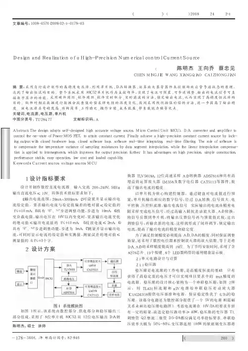
技术创新中文核心期刊《微计算机信息》(测控自动化)2008年第24卷第2-1期电源技术一种高精度数控直流电流源的设计与实现DesignandRealizationofaHigh-PrecisionNumericalcontrolCurrentSource(重庆工商大学)陈明杰王向乔蔡忠见CHENMINGJIEWANGXIANGQIAOCAIZHONGJIAN摘要:采用自行设计制作的高精度电压源,利用单片机、D/A转换器、运算放大器等器件来控制场效应管导通状态的原理,达到了输出恒流的目的。
整个系统采用89C52单片机作为主控部件,实现了电流可预置、可步进调整、输出的电流信号可直接数字显示的功能。
采用硬件闭环、软件闭环、软件实时积分、实时滤波的方法,锁定输出电流,从而实现了高精度恒流源的目的。
软件对相应数据进行数据分段查值补偿采样电阻的温度变化,段间采用线性插值补偿的方法,进一步提高了输出精度。
该电流源具有精度高、结构简单、工作稳定、操作方便、成本低廉、带负载能力强等优点。
关键词:电流源;电压源;单片机中图分类号:TU284.77文献标识码:AAbstract:Thedesignadoptsself-designedhighaccuratevoltagesource,MicroControlUnit(MCU),D/Aconverterandamplifiertocontroltheon-stateofPowerMOSFET,toattainconstantcurrent.Finallyachieveahigh-precisionconstantcurrentsourcebylock-ingoutputwithclosedhardwareloop,closedsoftwareloop,softwarereal-timeintegrating,real-timefiltering.Theroleofsoftwareistocompensatethetemperaturevarianceofsamplingresistancesbydatasegmentinterpolation,whilethelinearinterpolationcompensa-tionisappliedtointersegments,whichimprovestheoutputprecisionfurther.Ithasadvantagesonhighprecision,simpleconstruction,performancestable,easyoperation,lowcostandloadedcapability.Keywords:Currentsource,voltagesource,MCU文章编号:1008-0570(2008)02-1-0178-031设计指标要求设计并制作数控直流电流源。
2017毕业论文-数控恒流源的设计2017毕业论文-数控恒流源的设计兰州工业高等专科学校毕业论文摘要恒流源,是一种能够向负载提供恒定电流的电源。
恒流源的应用范围非常广泛,并且在许多情况下是必不可少的。
本文设计了一种基于单片机控制的数控直流恒流源。
该恒流源以AT89S52为控制核心,采用了高共模抑制比低温漂的运算放大器OP07和达林顿管TIP122构成恒流源的主体,配以高精度采样电阻及12位D/A芯片MAX532、16位A/D芯片AD7715,完成了单片机对输出电流的实时检测和实时控制。
人机接口采用4×4键盘及LED数码管显示器,控制界面直观、简洁,具有良好的人机交互性能。
在软件设计上采用增量式PID控制算法,即数字控制器的输出只是控制量的增量。
该系统已基本达到预期的设计目标,具有功能强、性能可靠、体积小、电路简单的特点,可以应用于需要高稳定度的小功率恒流源的领域。
关键词:恒流源;AT89S52;PID控制算法;数字控制。
The abstract Constant current, is one kind can provide theconstant current to the load the power source.The constant current application scope is extremely widespread, and in many situations is essential.This article has designed one kind the numerical control cocurrent constant current which controls based on the monolithic integrated circuit. This constant current take AT89S52 as the control core, has used operational amplifier OP07 and Darington which Gao Gongmu the rejection ratio low temperature floats manages the TIP122 constitution constant current the main body, matches by the high accuracy sampling resistance and 12 D/A chip MAX532, 16 A/D chip AD7715, has completed the monolithic integrated circuit to the output current real-time examination and the real-time control. The man-machine connection uses 4×4 the keyboard and the LED nixietube monitor, the control interface is direct-viewing, is succinct, has the good man-machine interaction es the increase type PID control algorithm in the software design, namely the digital controller output only is controls the quantity the increase. This system had achieved basically the anticipated design goal, has the function strongly, the performance reliable, the volume small, the electric circuit simple characteristic, may apply in needs the high stability the low power constant current domain. Key word: Constant current;AT89S52; PID control algorithm; Numerical control. 目录第1章绪论5 第2章系统的总体设计6 2.1 设计指标要求6 2.2 总体方案的选取及系统6 2.2.1 方案一:6 2.2.2 方案二:7 第3章系统的硬件设计8 3.1 单片机的功能介绍8 3.1.1 主要功能特性:8 3.1.2 引脚功能说明8 3.1.3 时钟电路及复位电路11 3.2 恒流源基本设计原理与实现方法13 3.2.1 引起稳定电源输出不稳定的主要原因13 3.2.2 恒流源的基本设计原理14 3.2.3 系统电源设计15 3.3 A/D 模块选择16 3.3.1 AD7715简介16 3.3.2 硬件电路设计18 3.4 D/A 模块选择19 3.4.1 MAX532简介19 3.4.2 硬件电路设计21 3.5 键盘接口电路设计22 3.5.1 键盘工作方式23 3.5.2 接口电路设计23 3.5.3 按键抖动及消除24 3.6 显示器接口电路设计25 第4章系统的软件设计27 4.1 控制算法27 4.2 软件流程图29 4.2.1 主程序流程图29 4.2.2 键盘中断子程序30 4.2.3 显示中断子程序31 第5章总结33 致谢34 参考文献35 附录A 总电路图36 第1章绪论恒流源,是一种能向负载提供恒定电流之电路。

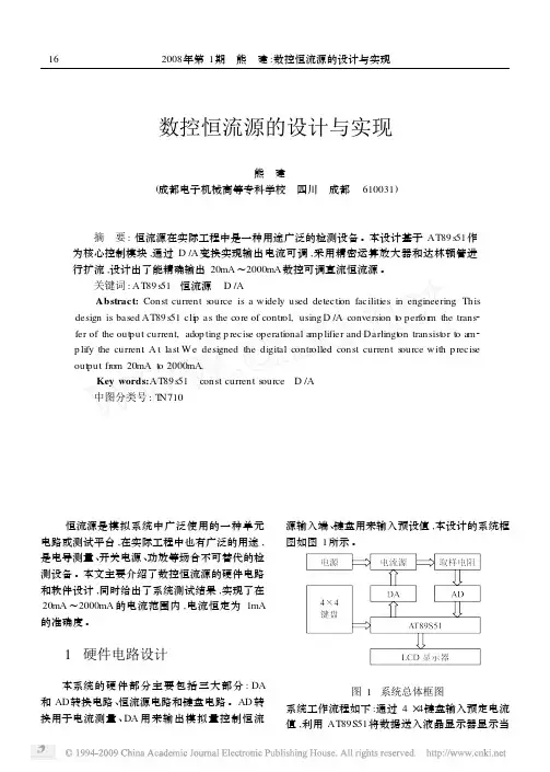
数控恒流源的设计与实现熊 建 (成都电子机械高等专科学校 四川 成都 610031)摘 要:恒流源在实际工程中是一种用途广泛的检测设备。
本设计基于AT89s51作为核心控制模块,通过D/A变换实现输出电流可调,采用精密运算放大器和达林顿管进行扩流,设计出了能精确输出20mA~2000mA数控可调直流恒流源。
关键词:AT89s51 恒流源 D/AAbstract:Const current s ource is a widely used detecti on facilities in engineering.This design is based AT89s51cli p as the core of contr ol,using D/A conversi on t o perfor m the trans2 fer of the out put current,adop ting p recise operati onal a mp lifier and Darlingt on transist or t o a m2 p lify the current.A t last W e designed the digital contr olled const current s ource with p recise out put fr om20mA t o2000mA.Key words:AT89s51 const s ource D/A中图分类号:T N710 恒流源是模拟系统中广泛使用的一种单元电路或测试平台,在实际工程中也有广泛的用途,是电导测量、开关电源、功放等场合不可替代的检测设备。
本文主要介绍了数控恒流源的硬件电路和软件设计,同时给出了系统测试结果,实现了在20mA~2000mA的电流范围内,电流恒定为1mA 的准确度。
1 硬件电路设计本系统的硬件部分主要包括三大部分:DA 和AD转换电路、恒流源电路和键盘电路。


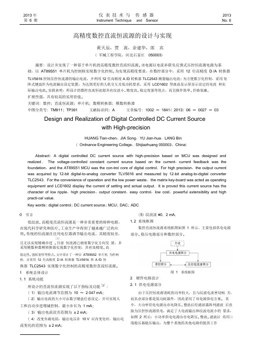
2013 年 仪 表 技 术 与 传 感 器2013 第 6 期Instrument Techniqueand SensorNo. 6高精度数控直流恒流源的设计与实现黄天辰,贾 嵩,余建华,郎 宾( 军械工程学院,河北石家庄 050003)摘要: 设计并实现了一种基于单片机的高精度数控直流恒流源。
该电源以电流串联负反馈式压控恒流源电路为基 础,以 AT89S51 单片机为控制核实现数字化控制。
为实现高精度要求,在数控部分中,采用 12 位高精度 D /A 转换器TLV5616 控制压控恒流源的输出电流,并利用 12 位高精度 A /D 转换器 TLC2543 测量输出电流; 为方便数字化控制,采用 矩阵式键盘作为电流输出设定装置; 为达到更好的人机交互及低功耗要求,采用 LCD1602 型液晶显示屏显示设定的电流 和实际输出电流。
实践表明: 所设计的数控直流恒流源具有纹波小、精度高、稳定度强等优点,而且操作简单、价格低廉、扩展性强,具有较高的实用价值。
关键词: 数控; 直流恒流源; 单片机; 数模转换器; 模数转换器中图分类号: TM911; TP391 文献标识码: A 文章编号: 1002 - 1841( 2013) 06 - 0027 - 03Design and Realization of Digital Controlled DC Current Sourcewith High-precisionHUANG Tian-chen ,JIA Song ,YU Jian-hua ,LANG Bin ( Ordnance Engineering College ,Shijiazhuang 050003,China )Abstract : A digital controlled DC current source with high-precision based on MCU was designed and realized . The voltage-controlled constant current source based on the current- current feedback was the foundation ,and the AT89S51 MCU was the con-trol core of digital control . For high precision ,the output current was acquired by 12-bit digital-to-analog converter TLV5616 and measured by 12-bit analog-to-digital converter TLC2543. For the convenience of operation and the low power waste ,the matrix key-board was acted as operating equipment and LCD1602 display the current of setting and actual output . It is proved this current source has the character of low ripple ,high precision ,output constant ,easy control ,low cost ,powerful extensibility and highpracti-cal value .Key words : digital control ; DC current source ; MCU ; DAC ; ADC0 引言低纹波、高精度直流恒流源是一种非常重要的特种电源, 在现代科学研究和医疗、工业生产中得到了越来越广泛的应 用。
华中科技大学文华学院毕业设计(论文)高精度恒流源设计学生姓名:学号:学部(系):专业年级:指导教师:职称或学位:高级工程师2010年5月21日目录摘要 (1)关键词 (1)Abstract (1)Key words (1)前言 (2)1.概述 (2)1.1 直流稳压电源的发展方向 (2)1.2 国内发展现状 (3)1.3 系统研究方向 (4)2.设计原理 (5)2.1设计原理 (5)2.2系统框图 (7)3.主要器件及EDA设计软件的介绍 (8)3.1 AT89C51简介 (8)3.2 开关管IGBT的工作原理 (11)3.3 数码管显示原理 (11)3.4 EDA设计软件 (13)4.硬件电路与数据测试 (20)4.1 整流滤波、初步稳压 (20)4.2 AT89C51主控部分 (21)4.3 DC/DC变换部分 (21)4.4 稳压部分 (22)4.5显示电路 (23)4.6数据测试与分析 (24)5.软件设计 (25)5.1 软件流程图 (25)参考文献 (26)致谢 (27)附录一 (28)附录二 (29)高精度恒流源设计摘要目前电源技术已逐步发展成为一门多学科互相渗透的综合性技术学科,它对现代通讯、电子仪器、计算机、工业自动化、电力工程、国防及某些高新技术提供高质量、高效率、高可靠性的电源起着关键作用。
本文介绍了一种基于单片机的智能稳压电源的设计方案,其核心技术是通过单片机控制开关管的占空比来实现对输出电压的步进调节。
该系统整合了AC/DC整流和DC/DC直流变换技术,系统主体由两大部分组成:为器件提供工作电源的AC/DC整流部分;实现输出电压可调的DC/DC直流变换部分。
系统由整流滤波模块、单片机控制模块、数码管显示模块、闭环调节稳压模块组成,系统的另一亮点在于可以实时显示,这弥补了传统稳压电源的不足。
关键词:51单片机;稳压电源;连续步进可调;开关管的占空比;High Precision Constant Current SourceAbstractPresent power technology has gradually developed into more than one discipline mutual penetration of integrated technical disciplines, its modern communications, electronics, computer, industrial automation, electrical work, some high-tech defense and provide high quality, high efficiency, high reliability of power plays a key role.This paper introduces a microcomputer-based Intelligent Power Supply design, the core technology is controlled by single chip switch duty cycle to achieve the output voltage of the step adjustment. The system incorporates AC / DC rectifier and DC / DC DC Converter technology, the system main body consists of two parts: the device supplies power to the AC / DC rectifier; to achieve output voltage of DC / DC DC transformation part. System by the rectifier module, microprocessor control module, digital control module, closed loop regulation voltage regulator modules, Another bright spot is that the system can display real-time, which make up the deficiencies of the traditional regulated power supply.Key Words:MCU; Regulated Power Supply; Continuously adjustablestep; Switch duty cycle;前言本文着重于探讨和设计一种高精度的可控的稳定电源,本文从直流稳压电源的目前发展现状说起,直流稳压电源目前的发展趋势是其设计的数字化和智能化,并与计算机技术的高度融合。
50 引言在仪器仪表中常需要用到高精度数字控制恒流源,主要表现在输出电流范围大,步进电流分辨力高[1]。
本文的目标是以200~240V、50Hz交流电源为输入,设计输出电流20mA~2000mA,步进1mA,电压≤10V的恒流源电路。
为此,基于集成运放和调整管构成的负反馈恒流源电路,合理计算电路参数,并设计由控制器、键盘、显示器和数模、模数转换器构成的控制、测量方案,达到给定电流值即能数字化控制输出需要的电流并进行测量的目的,同时满足测量误差的绝对值≤测量值的0.1%+3个字的要求。
1 系统方案设计系统组成如图1所示,采用单片机作为控制器,接收用户从键盘输入的电流预置值,控制D/A转换器输出电压信号Ui,作为恒流源电路的控制电压,实现数控输出恒定电流到负载。
电流通过采样电阻转化为电压,经A/D转换送回控制器,计算处理后由LCD显示实际电流值。
1.1 控制电路设计控制器选用AT89C52型号单片机,通过P0口驱动键盘,P3.5~P3.7和P2驱动LCD显示器,P1口驱动A/D转换和D/A转换电路,如图2所示。
其中LCD1602可模块显示汉字、数字、字母符号,4*4矩阵式键盘通过行、列扫描识别按键动作从而设置电流值,16个按键定义为0~9数字、+、-、确定、取消以及光标左移、右移功能键,支持随机输入和步进调整电流给定值。
单片机接收到电流给定值时经D/A转换器输出控制电压,控制恒流源电路输出电流,对采样电阻的电压进行A/D转换,显示电流实测值。
1.2 恒流源电路的组成原理利用集成运放和调整管组成恒流源电路,如图3所示。
其中集成运放采用TL082,具有低功耗、共模和差分电源范围宽、低输入偏置电流等特点[2]。
调整管采用型号为IRF640的N沟道增强型金属氧化物场效应管(MOSFET),开关速度快、导通阻抗小(不大于180m欧)及低热阻、低成本、坚固耐用等优点,常温下输出10V电压时漏极电流16A,功耗50W以下,适应于离线开关模式的电力供电,显示器电源、马达控制电路及通用开关应用[3]。
高精度数控恒流源的设计与实现宋林桂【摘要】为了满足可调温无纺布热切割机对恒流源的需求,文章阐述了一种基于单片机的高精度数控恒流源的设计和实现方法.该电源以电流串联负反馈式压控恒流源电路为基础,以AT89S52单片机为控制核实现数字化控制.为实现高精度要求,在数控部分中,要采用12位高精度数字模拟转换器(Digital Analog Converter,DAC)芯片TLV5616控制压控恒流源的输出电流,并利用16位高精度模数转换器(Analog to Digital Converter,ADC)芯片ADS1115测量输出电流.文章采用矩阵键盘设定电流输出值,采用LCD12864液晶屏显示设定的电流和负载两端电压值.测试结果表明,本恒流源在20 ~2000mA输出电流时,输出电流与给定值误差小于5mA.【期刊名称】《无线互联科技》【年(卷),期】2016(000)018【总页数】3页(P59-60,76)【关键词】AT89S52;恒流源;ADS1115;TLV5616【作者】宋林桂【作者单位】苏州健雄职业技术学院电气工程学院,江苏太仓215411【正文语种】中文高精度恒流源是一种非常重要的特种电源,在现代科学研究和医疗、工业生产中得到了越来越广泛的应用。
传统的恒流源往往用电位器调节输出电流,其精度较差,且无法实现精确步进。
目前,恒流源已朝着数字化方向发展,多采用模数和数模转换器实现数字化控制,具有高精度、高稳定性等特点[1]。
该系统主要由电源模块、恒流源电路模块、负载模块、单片机最小系统模块、键盘显示模块、ADC电路模块和DAC电路模块、LCD12864液晶显示电路以及4×4矩阵键盘电路构成,系统结构如图1所示。
2.1 电源电路系统中使用到集成运算放大器,集成运算放大器供电使用正负电源。
如图2所示,为了减少系统输出的纹波系数,系统选用±12V变压器把市电降成低压,变压器变压后经过整流滤波得到正直流电源DC+和负直流电源DC-,正电源DC+和负电源DC-为集成运算放大器提供正负电源。