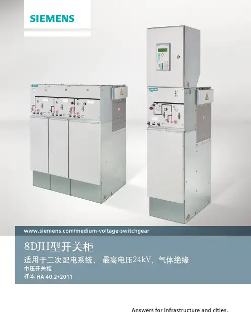
西门子公司SIEMENS 8DJ20智能一体化开关柜示范
- 格式:doc
- 大小:19.00 KB
- 文档页数:4
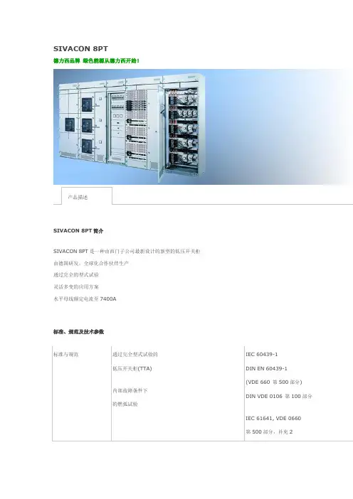
SIVACON 8PT德力西品牌绿色能源从德力西开始!SIVACON 8PT简介SIVACON 8PT是一种由西门子公司最新设计的新型的低压开关柜由德国研发,全球化合作伙伴生产通过完全的型式试验灵活多变的应用方案水平母线额定电流至7400A标准、规范及技术参数标准与规范通过完全型式试验的低压开关柜(TTA)内部故障条件下的燃弧试验IEC 60439-1DIN EN 60439-1(VDE 660 第500部分) DIN VDE 0106 第100部分IEC 61641, VDE 0660第500部分,补充2电气间隙与爬电距离额定冲击耐受电压8 kV过电压类别III污染等级 3 DIN EN 60439-1 (VDE 0660 第500部分)额定绝缘电压(Ui) 1000 V额定工作电压(Ue) 至690 V内部分隔形式 1 至形式4 IEC 60439-1, 第7.7 款, 60439-1表面处理支撑结构外壳门镀锌/粉末喷涂/涂漆镀锌/粉末喷涂/涂漆粉末喷涂/涂漆防护等级IP 30 至IP 54外形尺寸高: 2200, 2600mm宽: 400, 600, 800, 1000, 1200, 1600 mm深: 600, 800, 1000 ,1200 mm模块化结构主要特点一、骨架和外壳1. 骨架上安装孔采用25mm为模数,有多种组合方案2. 各种机动灵活的柜门,能满足不同要求3. 门的最大开启角度可至180°4. 弹簧门锁能可靠的防止门的意外弹开5. 柜体顶部带有压力释放装置二、水平母线系统1. 标准化设计的主母线位于柜体的顶部2. 主母线的最大额定电流可至7400 A3. 按客户的要求划分的额定电流等级4. 额定峰值耐受电流(Ipk) 可至375kA5. 主母线隔室与器件隔室单独隔离6. 从上方可方便的进行运输单元间母线的联接三、框架断路器方案1. 采用3WT或3WL断路器2. 每柜最多可装3个断路器3. 3极或4极4. 固定式或抽出式5. 关门时,具有试验及分离位置6. 短路强度Ipk 至375kA、Icw 至150 kA, 1 s、至100 kA, 3 s 安装方式:固定安装技术插入式技术插拔式技术抽出式技术前开门接线抽出式技术后开门接线。
第一章 8DA10型高压开关柜功能、特点8DA 系列可扩展、固定式安装断路器型开关柜主要在变电站和配电站中使用,并且可完成用户变电站的开关任务。
这些开关柜额定电压高达 40.5 kV,额定电流高达 3150 A 。
它们适用于 100 kA 的最大允许额定短路电流和 40 kA 的最大短路分断电流。
8DA 型固定安装断路器型开关柜具有以下特点:适合室内安装的金属外壳开关柜,出厂时已组装好,经过型式试验; 采用绝缘介质 SF6 气体;可安全触摸的电缆连接与互连系统并可连接固体绝缘母线和 SF6 气体绝缘母线;本柜型GIS为单母线结构;本柜型采用单极金属外壳;本柜型为免维护高压开关柜;采用逻辑机械联锁的完整开关柜联锁系统;气密性一次外壳,不受污物、湿气和小动物等环境因素的影响;具有较高的人员安全性; 具有较高的设备安全性。
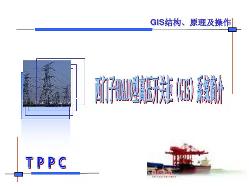
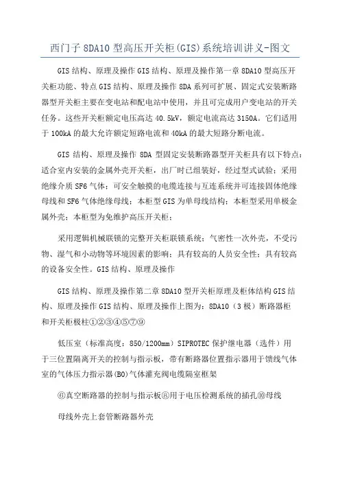
第二章 8DA10型开关柜原理及柜体结构上图为: 8DA10(3极)断路器柜和开关柜极柱①低压室(标准高度: 850/1200 mm)② SIPROTEC 保护继电器(选件)③用于三位置隔离开关的控制与指示板,带有断路器位置指示器④用于馈线气体室的气体压力指示器 (B0)⑤气体灌充阀⑥真空断路器的控制与指示板⑦电缆隔室⑧用于电压检测系统的插孔⑨框架⑩母线⑪母线外壳⑫三位置隔离开关⑬上套管⑭断路器外壳⑮真空灭弧室⑯电流互感器⑰下套管⑱开关柜连接外壳8DA10型开关柜为单母线三极开关柜,其结构大致可分为:(1)高压断路器柜;(2)高压断路器;(3)三位置隔离开关;(4)电流互感器;(5)电压互感器;(6)气室。
下面将就上述几部分组成的功能、特性进行简要介绍。
2.1 断路器柜2.1.1 功能断路器柜是 8DA 系列开关柜的基本柜型。
具有“进线”和“出线”功能。
它可携载或分断所有额定母线及馈线电流以及相应铭牌上标出的短路电流。
2.1.2 框架开关柜极柱和开关柜前端的支撑件,形成电缆连接隔室。
发布日期: 2021年5月订货号:C53000-L255D-A323-BSIPROTEC 多功能保护装置7SJ686V5.067SD686V5.067UT686V5.06冗余 IEC 60870-5-103通信手册前言目录7SJ686/7SD686/7UT686的产品注意事项1IEC 60870-5-103 兼容性2信息列表3索引西门子电力自动化有限公司 订货号:C53000-L255D-A323-B版权版权所有 © Siemens 2021。
未经书面授权,不得披露、复制、分发和编辑本文档,或者使用和传播文档内容。
Siemens 保留所有权利,其中包括因专利授权或注册实用新型或设计而获得的权利。
商标SIPROTEC 、DIGSI 、SIGRA 、SIGUARD 、SIMEAS SAFIR 、SICAM 和 MindSphere 是Siemens 的商标。
禁止任何未经授权的使用行为。
免责声明本手册信息仅包含产品的通用描述和/ 或性能特点,可能无法实时反映产品在进一步开发过程中被描述的或被修改的信息。
因此本手册所提供信息可能存在变更和偏差。
对产品所要求的性能特点,仅当其明确约定于所签署的合同中才具有约束力。
文件版本:V5.06.03发布日期2021.0537SJ686, 7SD686, 7UT686 通信手册C53000-L255D-A323-B, 发布日期2021.05前言手册内容本手册主要介绍了以下三方面的内容:•7SJ686/7SD686/7UT686的产品注意事项•冗余 IEC 60870-5-103 设备子协议适用对象保护工程师,通讯工程师,参与保护、自动化和控制装置的设置、测试和服务的人员,以及电厂和电站的操作人员。
其他文献此手册描述了冗余IEC60870-5-103设备子协议关于7SJ686、7SD686和7UT686装置的规定。
以下补充文献对冗余IEC 60870-5-103,7SJ686、7SD686和7UT686装置的功能、操作、装配以及调试做出了说明。

CE2N3341en Siemens Building Technologies3341RWD32RWD82Universal ControllerRWD32RWD82For comfort control in HVAC & R-Systems • Standalone electronic temperature controller with P or PI response • Operating voltage in accordance to type AC 230 V or AC 24 V • Control application selectable via Application Number • Active input scale can be selectable• Two universal inputs for Ni 1000, Pt 1000 temperature sensors &0…10 V signals• Unit can be set as ºC, ºF, % or no specified unit• One 3-position output or two two-position outputs, direct or reverse action • One digital input for day/night changeover• Entering or changing of all data via operating buttons on the controller, possi-ble without additional tools•PC connection for downloading canned applications via the software toolUseThe universal controllers are intended for Heating, Ventilating, Air-Conditioning and Refrigeration in comfort control plants. It can be mounted in a control panel or in the ARG62.21/ARG62.22 housing on ducts, walls and in plant rooms.HVAC&R ApplicationMeasurement and control of temperature, relative humidity, absolute humidity, en-thalpy, pressure differential, volumetric airflow and indoor air quality. The input scalecan be set from –100 units to 8,000 units.Functions Summary• ControllerStand-alone controller with one 3-position or two 2-position (ON/OFF) outputs withindependent adjustment on each sequence for direct acting and/or reverse acting.In 3-position operation, the controller exhibits PI response.• Auxiliary selectable functionUniversal input X2 for one of the following functions:−PI limiter function (Absolute & Relative)−Remote setpoint function−Cascade control function−Setpoint compensation−Winter/summer operation−Maximum priority•Digital input D1 for setpoint changeover day/nightInput & Output summaryInputs Outputs(either)Operating TypeUniversal Digital3-position2-position voltage reference2112AC 230 V RWD322112AC24V RWD82 AccessoriesName TypeProtective small enclosure for wall mounting ARG62.21Protective big enclosure for wall mounting ARG62.22Software Tool S3341A031EN0 Equipment combinationsThe following Landis & Staefa units can be connected to RWD32 and RWD82 universalcontrollers.Units Data sheet no.Sensor with LG Ni 1000 temperature sensing element17... to 19...Sensor with Pt 1000 temperature sensing element1846Sensor with DC 0...10 V measuring signal17... to 19...1721 / 1748Room temperature sensor with setpoint adjuster QAA25or QAA25/APRemote setpoint adjusters FZA21.11 + FZA61.1119...Air damper actuators with 3-position input46...Valve actuators with 3-position input45...2/113/11Other combinations with third-party units are possible, provided the input and output specifications match the RWD32 and RWD82.A software tool for controller application selection and parameter adjustment is avail-able. It is a user-friendly Windows® 95 (or above) based software tool which provides you a printout of the controller settings.FunctionsThe RWD32 and RWD82 are stand-alone universal controllers, which perform both primary and auxiliary control functions. The respective mode is defined by entering the corresponding configuration and setting parameters via the push buttons on the con-troller or the software tool.The RWD32 and RWD82 controllers can be programmed as follows:• 2-position controller:Q1 and Q2reverse and/or direct acting on each step • 3-position controller:Q1 or Q2reverse or direct actingONONLoad2 Reverse Acting Sequences (Dependent loops)(Application No.: 10-19)2 Direct Acting Sequences (Dependent loops)(Application No.: 50-59)LoadLoad2 Reverse Acting Sequences(Independent loops)(Application No.: 20-29)2 Direct Acting Sequences (Independent loops)(Application No.: 60-69)Reverse and Direct Acting Sequences(Application No.: 40-49)Software ToolController typeMain functionsDependent Control LoopsIndependent Control LoopsReverse and Direct Acting Control Loops4/11LoadReverse Acting Sequence (Application No.: 30-39)Direct Acting Sequence (Application No.: 70-79)The universal input X1 is used as the primary input for a Landis & Staefa Ni 1000 tem-perature sensor, a Pt 1000 temperature sensor or a 0…10 V DC active input.The universal input X2 is used as the secondary input for a Landis & Staefa Ni 1000temperature sensor, a Pt 1000 temperature sensor, an active / passive remote setpoint transmitter or a 0…10 V DC active input.The digital input D1 is used to select the day/night changeover. Changeover occurs via potential-free contacts between D1 and M.Each output Q (Q1, Q2) can be configured for either reverse or direct acting.Ventilating plant with temperature controlX1Room temperature Q1Heating, reverse action Q2Cooling, direct actionOne of the following auxiliary functions can be selected:• PI limiter function (Absolute & Relative)• Remote setpoint function • Cascade control function • Setpoint compensation • Winter/summer operation • Maximum priorityAdditionally, the day and night operation mode is available.The limiter function with PI control enables abso-lute(or relative) maximum or minimum limitation of the supply air temperature (X2).When the value drops below or exceeds the limiter setpoint, the limiter function controls and takes prior-ity over the main setpoint.3341s 02A remote setpoint transmitter (FZA21.11, QAA25 or QAA25/AP), connected to X2 and configured ac-cordingly, enables setpoint adjustment.Active measurement from 0...10 V DC corresponding adjustable range from –100 to 8000Passive measurement from 0…1000 Ω correspond-ing adjustable range from –100 to 80003341s 033-point Control LoopUniversal input X1Universal input X2Digital input D1Digital outputs Q ExampleAuxiliary functions PI limiter functionRemote setpoint5/11X2 Supply air temperature sensorYou can select the PI/PI room/supply air tem-perature cascade control . In this case, the virtual PI room temperature controller determines thesetpoint within the limiter setpoints for the PI supply air temperature controller.Maximum Priority, coolingIf the value (0…10 V) of the input X2 is greater than the calculated output of the 3-point cooling sequence, the output will use the X2 input value as output value.The temperature setpoint X1 is shifted by the tem-perature as measured at sensor X2.Configuration of the RWD32 or RWD82 defines the influence on setpoint X1.The example shows the room air temperature set-point as controlled by the outside temperature.A digital switch or anlog input between terminals X2 and M can be used to implement win-ter/summer changeover.Digital changeoverWhen the contact is closed, summer operation is selected. Reverse acting output (Q1 only) is set to direct action (cooling).Analog changeoverWhen the X2 input exceeds the setpoint, summer operation is selected. Reverse acting output (Q1only) is set to direct action (cooling).A contact between terminals D1 and M can be used to implement setpoint changeover for day/night operation.When the contact is open, the setpoints for day operation are selected.When the contact is closed, the setpoints for night operation are selected.During the night mode, the following auxiliary func-tions are disabled: remote setpoint, abso-lute/Relative limiter, setpoint compensation andmaximum priority.Cascade control Maximum PrioritySetpoint compensationWinter/Summer operationDay/night setpoint6/11Mechanical design The RWD32 & the RWD82 universal controllers are as per DIN 43 880 Gr. 1 require-ments.A protective housing is used to protect the controller when mounted outside a control panel, such as on ducts, walls and in plant rooms. Furthermore, the protective housing prevents inadvertent contact with voltage supplying parts such as the connecting termi-nals.The RWD32 or RWD82 clips into the protective housing.The cable entries are located at the top and the bottom of the protective housing.The front has an opening for the LCD display and the programming buttons.The RWD32 and RWD82 universal controllers can be mounted as follows:• In a standard electrical control cabinet as per DIN 43 880• Wall mounted in a protective housing• Front mounting with standard available installation elementsPlug-in screw terminalsThe RWD32 and RWD82 are operated by the buttons on the controller front. Additional tools are not necessary. A 9-pin port is provided for optional programming via the soft-ware tool.RWD32RWD82The LCD shows the following information for normal operation:• Current operating values (maximum 4 digits)• Current setpoints (day/night)• Application number • Control sequencing diagram • Auxiliary input value• Selected auxiliary functionThe controller has three operating buttons for the following functions:The SELECT G button is used to enter or save the value adjustment.To configure the controller, follow the instructions supplied with the controller.HousingProtective housing ARG62.21/ARG62.22Mounting optionsTerminalsOperating and display elementsLCDOperating buttons SELECT GConfiguration7/11Engineering notes Use this controller only for applications as described in the description on the title page (bold print) and the section "Use". Additionally, observe all conditions and restrictions imposed in this section and in "Technical data".The sections marked with a warning symbol contain technical safety requirements and restrictions. Observe all of these warnings as they directly relate to the protection of person and equipment.Installation notesThe RWD32 and RWD82 controllers can be mounted as follows:Observe all local installation and mounting regulations.A On a DIN rail (EN 50 022-35 x 7.5) at least 120 mm long for RWD82 and 170 mm long for RWD32B Wall mounted with 2 screwsCFront mounted using standard elements.e.g. 1x DIN rail 150 mm long for RWD82 and 195 mm long for RWD32,2x hexagonal placeholders 50 mm, washers and screws DIn the ARG62.21/ARG62.22 protective housingA B C D3341z02Standard cables can be used for the controller. However, when mounting in an envi-ronment greatly exposed to EMI, use only shielded cables.• The RWD32 is designed for AC 230 V operating voltage.• The RWD82 is designed for AC 24 V operating voltage.The low voltage must comply with the requirements for safety extra-low voltage (SELV)as per EN 60730.Use safety insulating transformers with double insulation as per EN 60742; they must be designed for 100 % on-time.When using several transformers in one system, the connection terminals G0 must be galvanically connected.Supplying voltages above AC 24 V to low voltage connections may damage or destroy the controller or any other connected devices. Additionally, connections to voltages exceeding AC 42 V endanger personal safety.Intended useElectrical installation8/11Commissioning notesA booklet is supplied with the RWD32 & RWD82 controller for commissioning.Observe the following:• The controller must be configured for plant-specific operation using standard appli-cation number.• Plant specific fine tuning can be performed if required (refer to the commissioning booklet).• Power supply to the controller and the connected devices must be guaranteed • Values and settings entered remain available even on power failure.Technical data Operating voltage RWD32Operating voltage RWD82Safety extra-low voltage (SELV) as perFrequency RWD32Frequency RWD82AC 230 V ±15 %AC 24 V ±20 %EN 6073050 Hz/60 Hz 50 Hz/60 Hz RWD32RWD826.5 VA 3.5 VA Actual and nominal values 4 digitsL&S Ni 1000 ΩPt 1000 ΩActive sensor0.5 °C 0.5 °CDepends on the setting range TransportClimatic conditions Temperature HumidityMechanical conditions IEC721-3-2Class 2K3−25...+70 °C <95 % r.h.Class 2M2OperationClimatic conditions Temperature Humidity IEC721-3-3Class 3K50...+50 °C <95 % r.h.HousingFront and with ARG62.21Front and with ARG62.22IP 20 as per EN 60529IP 30 as per EN 60529IP 30 as per EN 60529Automatic electrical controls forhousehold and similar useEN 60730In accordance with European Union directivesElectromagnetic compatibility EMC Low voltage directive Emissions Immunity Safety89/336 EEC 73/23 EEC EN 50081-1EN 50082-1EN 60730N474Screw terminals for cables withmin. 0.5 mm dia.max. 2 x 1.5 mm 2 or 2.5 mm 2General data Po w er supplyPower consumption LCDDisplay resolution for (these values do not relate to the controller accuracy)Environmental conditionsEnvironmental conditionsIP codeProduct standards Other international approval Terminals9/11RWD82RWD320.297 kg 0.465 kgController Measuring RangeMax. cable length for dia. 0.6 mm −50…+150 °C max. 300 m Controller Measuring RangeMax. cable length for dia. 0.6 mm −20…+180 °C max. 300 mRangeMax. cable length for dia. 0.6 mm DC 0…10 V corresponding toadjustable range from –100 to 8000(°C, °F, % or no unit)max. 300 mRangeMax. cable length for dia. 0.6 mm0...1000 Ω corresponding to adjustable range from –100 to 8000 (°C, °F, % or no unit)max. 300 m Polling voltage for control commands (D…M)Current consumptionDC 15 V <15 mARelay contacts (potential-free)VoltageMaximum ratingMinimum ratingAC 24...230 VAC 230 V, 4 A resistive, 3 A ind. (per relay terminal)DC 30 V, 4 AAC 19.2 V, 20 mA DC 5 V, 100 mADiagramsD1Digital input G, G0L, N AC 230 V supplyM Ground (G0) for signal inputs and universal inputs Q...Digital output, various voltages permissible AC 24...230 V X1Signal input (main input: LS Ni 1000, Pt 1000 and 0…10 V DC)X2Signal input (aux. Input: LS Ni1000, Pt 1000, 0 …10 V DC and 0…1000 Ω or 0…10 V DC remote setpoint)ToolCommunication port for PC (9-pin plug)Weight without pack-agingAnalog inputs X1, X2L&S Ni 1000 Ω at 0 °C Pt 1000 Ω at 0 °C Analog voltages(for measured variables in °C, % or without unit)Remote setpoints X2Digital input D1Digital outputs Q1, Q2Internal diagram10/11E1Electrical load 2-position control N1RWD32/82 controllers PC Personal computerQ1/Q2Potential-free relay contacts for 3-position or 2-position control in 2 steps S1Time clock or switchX1Main input (Termination G appears when X1 is an active sensor)X2Auxiliary input or remote setpoint (Termination G appears when X2 is an active sensor)Y1Actuator with 3-position control AC 24...230 VPlease note that if you use a DESKTOP computer, the TOOL signal ground is galvani-cally connected to G0 inside the controller. If the signal line of the computer is grounded to Earth, the G0 line after TOOL connection will be Earthed as well.This will change from SELV to a PELV.Connection diagramNote11/11Siemens Building Technologies RWD32/RWD82 Universal controllerCE2N3341en Landis & Staefa Division17.07.2001Dimensions3341m 02RWD323341m 01RWD82150200ARG62.2161.2ARG62.21ã2001 Siemens Building Technologies Ltd.Subject to alteration。
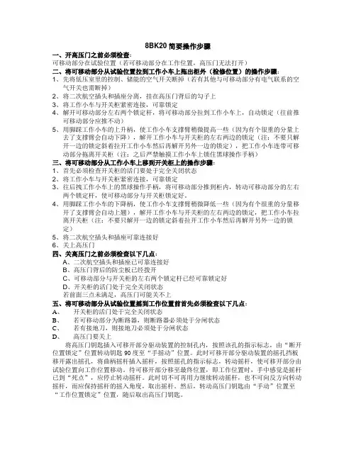
8BK20简要操作步骤一、开高压门之前必须检查:可移动部分在试验位置(若可移动部分在工作位置,高压门无法打开)二、将可移动部分从试验位置拉到工作小车上拖出柜外(检修位置)的操作步骤:1、先将低压室里的控制、储能的空气开关断掉(若有其他与可移动部分有电气联系的空气开关也需断掉)2、将二次航空插头和插座分离,挂在高压门背后的勾子上3、将工作小车与开关柜紧密连接,可靠锁定4、解开可移动部分左右两个锁定杆,将可移动部分拉到工作小车上,自动锁定(往前推可移动部分应推不动)5、用脚踩工作小车的上升柄,使工作小车支撑臂稍微提高一些(因为有个很重的分量上去了支撑臂会自动下降),解开工作小车与开关柜的左右两边的锁定(注:不要只解开一边的锁定斜着拉开工作小车然后再解开另外一边的锁定),把工作小车连带可移动部分拖离开关柜(注:之后严禁触摸工作小车上锁住黑球操作手柄)三、将可移动部分从工作小车上移到开关柜上的操作步骤:1、首先必须检查开关柜的活门要处于完全关闭状态2、将工作小车与开关柜紧密连接,可靠锁定3、往后拽工作小车上的黑球操作手柄,将可移动部分推到柜内,转动可移动部分的左右两个锁定杆,使可移动部分与开关柜锁定好。
4、用脚踩工作小车的下降柄,使工作小车支撑臂稍微降低一些(因为有个很重的分量移开了支撑臂会自动上翘),解开工作小车与开关柜的左右两边的锁定,把工作小车拉离开关柜(注:不要只解开一边的锁定斜着拉开工作小车然后再解开另外一边的锁定)5、将二次航空插头和插座可靠连接好6、关上高压门四、关高压门之前必须检查以下几点:A、二次航空插头和插座已可靠连接好B、高压门背后的防尘板已经拨开C、可移动部分与开关柜的左右两个锁定杆已经可靠锁定好D、开关柜的活门处于完全关闭状态若前面三点未满足,高压门可能关不上五、将可移动部分从试验位置摇到工作位置前首先必须检查以下几点:A、开关柜的活门处于完全关闭状态B、若可移动部分为断路器,则断路器必须处于分闸状态C、若有接地刀,则接地刀必须处于分闸状态D、高压门要关上将高压门钥匙插入可移开部分驱动装置的控制孔内,按照该孔的指示标志,由“断开位置锁定”位置转动钥匙90度至“手摇动”位置。
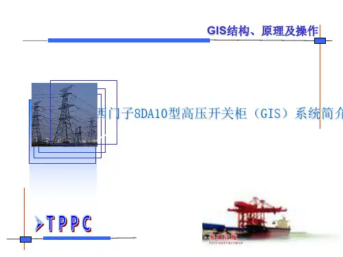
西门子8DA10型高压开关柜(GIS)系统培训讲义-图文GIS结构、原理及操作GIS结构、原理及操作第一章8DA10型高压开关柜功能、特点GIS结构、原理及操作8DA系列可扩展、固定式安装断路器型开关柜主要在变电站和配电站中使用,并且可完成用户变电站的开关任务。
这些开关柜额定电压高达40.5kV,额定电流高达3150A。
它们适用于100kA的最大允许额定短路电流和40kA的最大短路分断电流。
GIS结构、原理及操作8DA型固定安装断路器型开关柜具有以下特点:适合室内安装的金属外壳开关柜,出厂时已组装好,经过型式试验;采用绝缘介质SF6气体;可安全触摸的电缆连接与互连系统并可连接固体绝缘母线和SF6气体绝缘母线;本柜型GIS为单母线结构;本柜型采用单极金属外壳;本柜型为免维护高压开关柜;采用逻辑机械联锁的完整开关柜联锁系统;气密性一次外壳,不受污物、湿气和小动物等环境因素的影响;具有较高的人员安全性;具有较高的设备安全性。
GIS结构、原理及操作GIS结构、原理及操作第二章8DA10型开关柜原理及柜体结构GIS结构、原理及操作GIS结构、原理及操作上图为:8DA10(3极)断路器柜和开关柜极柱①②③④⑤⑦⑨低压室(标准高度:850/1200mm)SIPROTEC保护继电器(选件)用于三位置隔离开关的控制与指示板,带有断路器位置指示器用于馈线气体室的气体压力指示器(B0)气体灌充阀电缆隔室框架⑥真空断路器的控制与指示板⑧用于电压检测系统的插孔⑩母线母线外壳上套管断路器外壳三位置隔离开关真空灭弧室电流互感器下套管开关柜连接外壳GIS结构、原理及操作8DA10型开关柜为单母线三极开关柜,其结构大致可分为:(1)高压断路器柜;(2)高压断路器;(3)三位置隔离开关;(4)电流互感器;(5)电压互感器;(6)气室。
下面将就上述几部分组成的功能、特性进行简要介绍。
GIS结构、原理及操作2.1断路器柜2.1.1功能断路器柜是8DA系列开关柜的基本柜型。
第一章8DA10型高压开关柜功能、特点8DA 系列可扩展、固定式安装断路器型开关柜主要在变电站和配电站中使用,并且可完成用户变电站的开关任务。
这些开关柜额定电压高达40.5 kV,额定电流高达3150 A 。
它们适用于100 kA 的最大允许额定短路电流和40 kA 的最大短路分断电流。
8DA 型固定安装断路器型开关柜具有以下特点:➢适合室内安装的金属外壳开关柜,出厂时已组装好,经过型式试验;➢采用绝缘介质SF6 气体;➢可安全触摸的电缆连接与互连系统并可连接固体绝缘母线和SF6 气体绝缘母线;➢本柜型GIS为单母线结构;➢本柜型采用单极金属外壳;➢本柜型为免维护高压开关柜;➢采用逻辑机械联锁的完整开关柜联锁系统;➢气密性一次外壳,不受污物、湿气和小动物等环境因素的影响;➢具有较高的人员安全性;➢具有较高的设备安全性。
第二章8DA10型开关柜原理及柜体结构➢上图为:8DA10(3极)断路器柜和开关柜极柱①低压室(标准高度:850/1200 mm)②SIPROTEC保护继电器(选件)③用于三位置隔离开关的控制与指示板,带有断路器位置指示器④用于馈线气体室的气体压力指示器(B0)⑤气体灌充阀⑥真空断路器的控制与指示板⑦电缆隔室⑧用于电压检测系统的插孔⑨框架⑩母线⑪母线外壳⑫三位置隔离开关⑬上套管⑭断路器外壳⑮真空灭弧室⑯电流互感器⑰下套管⑱开关柜连接外壳8DA10型开关柜为单母线三极开关柜,其结构大致可分为:(1)高压断路器柜;(2)高压断路器;(3)三位置隔离开关;(4)电流互感器;(5)电压互感器;(6)气室。
下面将就上述几部分组成的功能、特性进行简要介绍。
2.1 断路器柜2.1.1 功能断路器柜是8DA 系列开关柜的基本柜型。
具有“进线”和“出线”功能。
它可携载或分断所有额定母线及馈线电流以及相应铭牌上标出的短路电流。
2.1.2 框架开关柜极柱和开关柜前端的支撑件,形成电缆连接隔室。
2.1.3 低压室①用于安放保护、控制、测量和计量装置;②带有断路器的插入式电缆以及位于C形导轨上、用于进线和出线电缆(如母线)的三位置隔离开关操作机构;③可将各个装置安装在门内或低压室内的安装板上2.1.4 开关柜极柱①极柱是前后布置的。
西门子中压开关柜智能化技术升级示范中压开关柜智能化技术升级示范西门子8DH10、8DJ20、SDJH 系列开关柜产品经过我们的技术升级,为配电网智能化建设提供开放、灵活的解决方案和优质电气设备。
SIEMENS公司作为国际上知名电气设备制造商,在电力和过程自动化产品系列中组合为电气系统提供IT系统等解决方案。
SIEMENS公司凭借创新工业设计和智能制造技术,借助系统的模块化制造,可以简化整个制造和安装流程,。
使生产效率得到提升。
电气设备智能化是电气制造企业必须考虑的问题,智能制造就是要生产出智能化的产品,在加快实现工业信息化的过程中,电气设备如果不是智能化的,那么这种设备就落后,今后被淘汰的可能性就很大。
西门子8DH10、8DJ20、SDJH 系列开关柜产品经过我们的技术升级,为配电网智能化建设提供开放、灵活的解决方案和优质电气设备。
一、西门子8DH10 8DJ20SDJH 系列开关柜西门子8DH10开关柜与8DJ20、SDJH 系列开关柜都是SF6气体绝缘开关柜,两者的区别是西门子8DH10开关柜带有扩展功能,可以任意扩展,可以带PT柜、计量柜;西门子8DJ20开关柜方案是固定的,无法扩展,多用于户外开闭所,电缆分接箱等无需计量的二次配电系统中。
西门子8DH10开关柜在工厂装配的户内(外)式全封闭10kV金属铠装开关设备,最高电压至24kV,额定馈线电流至630A,最大线线电流至1250A。
西门子8DJ20开关柜适用于各种变电站-包括在极端恶劣的环境条件下,例如:工业环境,潮湿、多沙或粉尘地区,简易的户外变电站。
西门子8DJ20外形体尺寸长1400mm 宽850mm 高1400mm打开箱门后柜体尺寸长1600mm 高1600mm。
西门子公司SIEMENS 8DJ20智能一体化开关柜示范
随着电网基础设施建设和电力能源投入的发展,电气成套设备需求量逐年增加,产品升级换代速度加快,生产设备及加工工艺有了明显改进、电气设备智能化、一二次融合技术、集成一体化等设备性能有了明显的提高。
一次设备是指直接用于生产、输送和分配电能的生产过程的高压电气设备。
它包括断路器、隔离开关、自动开关、刀闸开关、电缆母线、输电线路、电力电缆等。
由一次设备相互连接,构成配电设备开关或进行其分合闸操作过程的电气设备称为一次设备。
也称为无源组件。
二次设备是指对一次设备的工作进行监测、控制、调节、保护以及为运行、维护人员提供运行工况或生产指挥信号所需的低压电气设备。
由二次设备相互连接,构成对一次设备进行监测、控制、调节和保护的电气设备称为二次设备。
也称为有源组件。
一、二次设备融合关键技术
由于各种电器元件安装位置不同,在构成一个完整的电气控制系统时,就必须划分组件。
1、把功能类似的元件用模块化的形式组合在一起;
(1)尽可能减少组件之间的连线数量,同时把接线关系密切的控制电器置于同一组件中;
(2) 减少电压等级采用统一的供电电压
(3) 可把外形尺寸、功能相近的电器用模块的形式组合在一起;
(4)为了电气控制系统便于检查与调试,把需经常调节、维护和易损元件组合在一起。
2、在划分电气控制柜组件的同时要解决组件之间、电气箱之间以及电气箱与被控制装置之间的连线方式:
电气控制柜各部分及组件之间的接线方式一般应遵循以下原则:
(1)开关电器、控制板的进出线一般采用接线端头或接线鼻子连接,这可按电流大小及进出线数选用不同规格的接线端头或接线鼻子;
(2)电气柜、控制柜、柜(台)之间以及它们与被控制设备之间,采用接线端子排或工业联接。