8780系列说明书
- 格式:pdf
- 大小:164.20 KB
- 文档页数:2
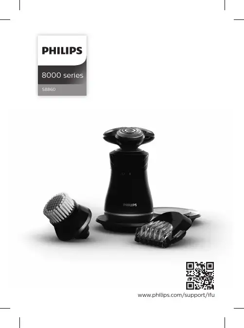
8000 seriesS8860/support/ifuEnglish 6简体中文 30General description (Fig.1)1Protection cap for cleansing brush attachment2Click-on cleansing brush attachment3Protection cap for shaving unit4Click-on shaving unit5On/off ring6On/off indications7Handle8Battery low indicator9Charging pad10Charging platform11Charging indicator12USB plug13Socket for USB plug14Supply unit15Cleaning brush16Click-on beard styler attachment17Comb for beard styler attachmentImportant safety informationRead this important information carefully beforeyou use the appliance and its accessories and saveit for future reference. The accessories suppliedmay vary for different products.Danger-Keep the supply unit dry.6EnglishWarning -The appliance is a Class IIIconstruction.-To charge the battery, only usethe detachable supply unit(supply unit, type HQ87.Charging pad, type HQ8508)provided with the appliance.-This appliance can be used bychildren aged from 8 years andabove and persons withreduced physical, sensory ormental capabilities or lack ofexperience and knowledge ifthey have been givensupervision or instructionconcerning use of the appliancein a safe way and understandthe hazards involved. Childrenshall not play with theappliance. Cleaning and usermaintenance shall not be madeby children without supervision.7English-Always check the appliancebefore you use it. Do not usethe appliance if it is damaged,as this may cause injury. Alwaysreplace a damaged part withone of the original type.-Do not open the appliance toreplace the rechargeablebattery.Caution-Never immerse the charging pad in water.-Always make sure the charging pad iscompletely dry before you connect it to the wall socket.-Never use water hotter than 60°C to rinse the shaver.-Only use this appliance for its intended purpose as shown in the user manual.-The charging pad is not intended for use in a car. It may interfere with the automotive electronic systems.-For safety reasons, do not use the shaver while you drive a car.-For hygienic reasons, the appliance should only be used by one person.8English-Never use compressed air, scouring pads,abrasive cleaning agents or aggressive liquids such as petrol or acetone to clean the appliance.-Water may trickle out of the shaver after your rinse it. This is normal and notdangerous because all electronics areenclosed in a sealed power unit inside the shaver.-Do not use the supply unit in or near wallsockets that contain an electric air freshener to prevent irreparable damage to the supply unit.Electromagnetic fields (EMF)This Philips appliance complies with all applicablestandards and regulations regarding exposure toelectromagnetic fields.General-This shaver is waterproof. It is suitable for use inthe bath or shower and for cleaning under thetap.-The supply unit is suitable for mains voltagesranging from 100 to 240 volts.-The supply unit transforms 100-240 volts to asafe low voltage of less than 24 volts.9EnglishChargingCharge the appliance before you use it for the first time and when the battery low indicator indicates that the battery is almost empty.Note: The shaver is Qi compliant.Charging takes approx. 2 hours. A fully charged appliance has a operating time of up to 30minutes.Tip: If your smartphone is compliant with Qi charging,you can also use the charging pad tocharge your smartphone.Put the supply unit in the wall socket and place the appliance onto the charging platform of the charging pad.-The charging pad bleeps when the appliance is correctly placed onto the chargingplatform.2After charging, remove the supply unit from the wall socket.Battery chargingBattery lowWhen the battery is almost empty, the battery low indicator flashes orange. 10EnglishBattery fully chargedUsing the applianceSwitching the appliance on and off1To switch on the appliance, turn the on/off ringanticlockwise to the 'on' indication (I).2To switch off the appliance, turn the on/off ringclockwise to the 'off' indication (0).ShavingSkin adaptation periodYour first shaves may not bring you the result youexpect and your skin may even become slightlyirritated. This is normal. Your skin and beard needtime to adapt to any new shaving system. To allowyour skin to adapt to this new appliance, we adviseyou to shave regularly (at least 3 times a week) andexclusively with this appliance for a period of 3weeks.Dry shaving1Switch on the appliance.2Move the shaving heads over your skin incircular movements to catch all hairs growing indifferent directions. Make sure each shavinghead is fully in contact with the skin. Exertgentle pressure for a close, comfortable shave.Note: Do not press too hard, this can cause skin irritation.3Switch off the appliance.4Clean the appliance after every use.Wet shavingFor a more comfortable shave, you can also use this appliance on a wet face with shaving foam or shaving gel.To shave with shaving foam or shaving gel, follow the steps below:1Apply some water to your skin.2Apply shaving foam or shaving gel to your skin.3Rinse the shaving unit under the tap to ensure that the shaving unit glides smoothly over your skin.4Switch on the appliance.5Move the shaving heads over your skin in circular movements to catch all hairs growing in different directions. Make sure each shavinghead is fully in contact with the skin. Exertgentle pressure for a close, comfortable shave.Note: Rinse the shaving unit regularly to ensure that it continues to glide smoothly over yourskin.6After use, rinse and dry your face gently and clean the appliance (see 'Cleaning andmaintenance').Note: Make sure you rinse all foam or shavinggel off the appliance.Using click-on attachmentsRemoving or attaching the click-on attachment1Make sure the appliance is switched off.2Pull the attachment straight off the appliance.Note: Do not twist the attachment while youpull it off the appliance.3Insert the lug of the click-on attachment intothe slot in the top of the appliance. Then pressdown the attachment to attach it to theappliance (' click').You can use the beard styler attachment with thecomb attached to style your beard at one fixedsetting, but also at different length settings. Youcan also use it to pre-trim any long hairs beforeshaving for a more comfortable shave.The length settings on the beard styler attachmentcorrespond to the remaining hair length aftercutting and range from 1 to 5mm (3/64 - 3/16in).1Attach the attachment to the appliance ('click').Slide the comb straight into the guiding grooveson both sides of the beard styler attachment(‘click’).You can use the beard styler attachment without the comb to contour your beard, moustache, sideburns or neckline to a length of 0.5mm (1/32Use the rotating cleansing brush with your daily cleansing cream. The cleansing brush removes oiland dirt, contributing to a healthy and oil-free skin.face.Your face is now ready for the next step of your daily skincare routine.10Clean the cleansing brush after use (see 'Cleaning the click-on attachment').Cleaning and maintenance Cleaning the applianceClean the shaver after every shave for optimal performance.1Switch off the appliance.2Rinse the shaving unit under a warm tap.Be careful with hot water. Always check if the water is not too hot, to prevent burning yourhands.3Pull the shaving head holder off the bottom part of the shaving unit.4Rinse the shaving head holder under a warmtap.Thorough cleaningWe advise you to clean the shaving headsthoroughly once a month or when the shaver doesnot shave as well as it used to.Note: The shaving heads are locked by a blue or anorange retaining ring.Follow the correct instructions.1Switch off the shaver.2Pull the shaving head holder off the bottom part of the shaving unit.3Rinse the hair chamber and shaving head holder under the tap.4Turn the retaining ring anticlockwise and lift it off the shaving head.Repeat this process for the other retaining rings.Place them aside in a safe place.4Remove the cutting unit from the beard styler attachment. By pushing the cutting unit from the beard styler attachment you can remove any hairs that have accumulated inside the beard styler. You can also rinse the back of thecutting unit.5Rinse cut hairs out of the beard styler attachment.6Carefully shake off excess water and leave the comb, cutting unit and beard styler attachment to dry before next usage.7When the cutting unit is dry attach it to the beard styler attachment.8When the comb is dry attach it to the beardstyler attachment.9For optimal performance, lubricate the teeth ofthe attachment with a drop of sewing machineoil regularly.The cleansing brush attachment should bereplaced every 3 months or earlier if the brushhairs are bent or damaged (see 'Orderingaccessories').1Switch off the appliance.2Detach the brush head from the attachmentholder.3Throw away the used brush head (see chapter'Recycling') .4Attach the new cleansing brush head to thebrush base.Replacing the shaving heads2yrsFor maximum shaving performance, we advise youto replace the shaving heads every two years.Replace damaged shaving heads immediately.Always replace the shaving heads with originalPhilips shaving heads (see 'Ordering accessories'). 22English1To replace the shaving heads, remove theshaving heads from the shaving head holderone by one. See chapter Thorough Cleaning forthe instructions on how to remove the retaining rings and shaving heads.Note: The shaving heads are locked by a blue or an orange retaining ring. Follow the correctinstructions.To buy accessories or spare parts, visit/service or go to yourPhilips dealer. You can also contact the PhilipsConsumer Care Center in your country (see theinternational warranty leaflet for contact details).The following accessories and spare parts areavailable:-SH90 Philips shaving heads-RQ560 Philips cleansing brush head-RQ111 Philips beard styler-HQ110 Philips Shaving head Cleaning Spray23EnglishRecycling-Do not throw away the product with the normalhousehold waste at the end of its life, but handit in at an official collection point for recycling.By doing this, you help to preserve theenvironment.-This product contains a built-in rechargeablebattery which shall not be disposed of withnormal household waste. Please take yourproduct to an official collection point or aPhilips service center to have a professionalremove the rechargeable battery.-Follow your country’s rules for the separatecollection of electrical and electronic productsand rechargeable batteries. Correct disposalhelps prevent negative consequences for theenvironment and human health.Warranty and supportIf you need information or support, please visit/support or read theinternational warranty leaflet.Warranty restrictionsThe shaving heads (cutters and guards) are notcovered by the terms of the international warrantybecause they are subject to wear.TroubleshootingThis chapter summarizes the most commonproblems you could encounter with the product. Ifyou are unable to solve the problem with theinformation below, visit /supportfor a list of frequently asked questions or contactthe Consumer Care Center in your country.24EnglishProblem Possible cause SolutionThe charging indicator on the charging pad lights up red.Wrong supply unitused or supply unitmalfunction (e.g. nooriginal Philipssupply unit is used)Use the original Philips7.5W supply unit.Metal objects areplaced on the padduring charging(e.g. paper clip,coins, etc)Remove any metal objectsfrom the pad.Shaver/pad chargemalfunction (e.g.either pad orshaver not workingproperly)If the first and secondsolution do not solve theissue, return the applianceto Customer Care Centre inyour country.The appliance does not charge. The appliance isnot placedcorrectly onto thecharging pad.Place the appliance ontothe charging platform ofthe charging pad. Whenplaced correctly, thecharging pad will make asound and the chargingindicator on the chargingpad starts flashing white. The wall socketinto which youhave inserted thesupply unit is notlive.Verify whether there is apower failure and if thewall socket to which youconnect the charging plateis live. If you use a wallsocket in a bathroomcabinet, you may need toswitch on the light toactivate the socket.25EnglishProblem Possible cause SolutionIf the charging light on the charging plate still does not light up or if the appliance still does not charge, take it to your Philips dealer or the nearest Philips service centre.The appliance does not work. The battery is empty.Charge the appliance.The appliance is switched off.Turn the on/off ring anticlockwise to the 'on'indication (I).The shaving head holder is soiled or damaged to such an extent that the motor cannot run.Clean the shaving headsthoroughly or replace them(see 'Replacement'). Alsosee 'Hairs or dirt obstruct the shaving heads' for a detailed description of how to clean the shaving heads thoroughly.The appliance does not switch 'on' after charging Turn the on/off ring back and forth, the appliance should now switch 'on'.The appliance does not shave as well as it used to.The shaving heads are damaged or worn.Replace the shaving heads.Hairs or dirt obstruct the shaving heads.Clean the shaving heads inthe regular way (see 'Cleaning and maintenance') or clean them thoroughly.26EnglishProblem Possible cause SolutionTo clean the shaving headsthoroughly, remove theshaving heads from theshaving head holder oneby one (see'Replacement'). Thenseparate the cutter from itsguard and rinse eachmatching set under thetap. After rinsing, place thecutter back into itscorresponding guard.Finally, put the shavingheads back into theshaving head holder (see'Replacement').I do not know if the cleansing brush is suitable for use on my skin. The cleansing brush is suitable for all skin types. However, do not use the brush on dry, chapped skin, open wounds, healing wounds, skin recovering from surgery or if you suffer from a skin disease or skin irritation, such as severe acne, sunburn, skin infection, skin cancer, inflammation, eczema, psoriasis etc. Do not use the cleansing brush if you are taking steroid-based medication.27EnglishProblem Possible cause SolutionThe brush feels too harsh on the skin. If you experience the brush head as too harsh, we advise you to start using the Sensitive or Extra Sensitive brush head. The Sensitive and Extra Sensitive brush heads have softer bristles. We recommend the Sensitive brush head for sensitive skin and the Extra Sensitive brush head for extra sensitive and dry skin.I don’t know with which cleansing products I can use the brush head.We advise you to cleanse your skin with your favorite cleanser. You can use cleansing gel, foam, oil,milk or lotions. Please do not use scrub cream or gel with particles.My smartphone does not charge when placed onto the charging pad.The smartphone isnot placed correctly onto the charging pad. Place the smartphone onto the charging platform ofthe charging pad. When placed correctly, the charging pad will make a sound and the charging indicator on the charging pad starts flashing white.The wall socket into which you have inserted the adapter is not live.Verify whether there is apower failure and if thewall socket to which you connect the charging plate is live. If you use a wall socket in a bathroom cabinet, you may need to switch on the light to activate the socket.28EnglishProblem Possible cause SolutionThe smartphone is not compatible with Qi charging.Your smartphone might not be compatible with Qi charging; contact smartphone’s manufacturer or retailer.The beard styler does not trim as well as it used to.Hairs or dirtobstruct the cuttingelement.Clean the beard styler.The trimmingelement needs tobe lubricated.Lubricate the teeth of thebeard styler attachmentwith a drop of sewingmachine oil.The beard styler stopped working.The beard styler isdamaged or worn.Replace the beard stylerattachment.29English一般说明(图 1)1洁面刷附件保护盖2卡入式洁面刷附件3剃须刀头部件保护盖4卡入式剃须刀头部件5开/关环6开/关指示7手柄8电池电量不足指示灯9充电基座10充电架11充电指示灯12USB 插头13USB 插头接口14电源部件15清洁刷16卡入式胡须造型器附件17适用于胡须造型器附件的修剪梳重要安全信息使用本产品及其附件之前,请仔细阅读本重要信息,并妥善保管以供日后参考。
安装指南Micro870 可编程控制器 24V DC扩展电源产品目录号 2085-EP24VDC主题页码用户重要信息2环境和机壳4北美危险场所使用认证5防止静电放电6关于电源9安装电源9系统组装11电源接线13技术参数142罗克韦尔自动化出版物 2085-IN008A-ZH-P - 2018 年3 月Micro870 可编程控制器 24V DC 扩展电源用户重要信息在安装、配置、操作或维护本产品前,请仔细阅读本文档以及其他资源部分列出的文档,以了解有关此设备的安装、配置和操作信息。
用户需要熟悉安装和接线说明以及所有适用规范、法律和标准的相关要求。
安装、调节、投入运行、使用、装配、拆卸和维护等活动都需要由经过适当培训的人员遵照适用的操作规范来执行。
如果未按制造商指定的方式使用设备,则设备提供的保护功能可能会受到影响。
对于由于使用或应用此设备而导致的任何间接损失或连带损失,罗克韦尔自动化在任何情况下都不承担任何责任。
本手册中的示例和图表仅供说明之用。
由于任何特定的安装存在很多差异和要求,罗克韦尔自动化对于依据这些示例和图表所进行的实际应用不承担任何责任和义务。
对于因使用本手册中所述信息、电路、设备或软件而引起的专利问题,罗克韦尔自动化不承担任何责任。
未经罗克韦尔自动化公司书面许可,任何单位或个人不得复制本手册之全部或部分内容。
在整本手册中,我们在必要的地方使用了以下注释,来提醒您注意相关的安全事宜。
警告:标识在危险环境下可能导致爆炸,进而导致人员伤亡、物品损坏或经济损失的操作或情况。
注意:标识可能造成人身伤害或死亡、财产损坏或经济损失的行为或情况。
注意符号可帮助您确定危险情况,避免发生危险,并了解可能的后果。
重要信息标识对成功应用和理解产品有重要作用的信息。
罗克韦尔自动化出版物 2085-IN008A-ZH-P - 2018 年3 月3Micro870 可编程控制器 24V DC 扩展电源标签可能位于设备表面或内部,以提供特定警示。

HLZ9351GYY运油半挂车使用说明书盘锦辽河油田环利专用车制造有限公司目录总述:运油半挂车结构和主要参数一、常规半挂车底盘部分1、车辆定期维护2、车辆使用和操作及基本安全注意事项3、检查保养要领4、润滑5、故障原因及排除方法6、随车工具7、底盘主要部件的明细特征及使用说明8主要易损件清单二运油罐部分1、主要结构及工作原理2、操作与使用说明3、维修保养及使用注意事项4、贮存5、随车工具及技术资料一、概述为了正确使用和安全操作车辆,有计划地做好维护保养工作使车辆经常处于良好的状态,我们编写这本使用说明书。
本说明书着重介绍半挂车的基本结构、操作规程、注意事项和维护保养。
希望使用者在使用之前通读本说明书,严格按其规定进行使用、操作和维护。
若有不清楚的地方可以与本公司售后服务处联系。
由于本公司产品的结构和性能总会不断改进和完善,因此有可能出现与本说明书不同之处,敬请谅解,并热忱欢迎使用者对本公司产品提出宝贵的意见。
本厂生产的运油半挂车由半挂车底盘、罐体和管路系统组成。
该车容量大,结构合理,适合公路运输。
运油半挂车结构和主要参数主要参数:外型尺寸(长×宽×高)(mm):11500×2500×3700总质量(Kg):35280整备质量(kg):8780额定载质量(kg):26500接近角/离去角(°):-/15前悬/后悬(mm):-/1800轴距(mm):5880+1310+1310轴数:3轴荷:22660(并装三轴)轮胎数:12轮胎规格:12.00-20/12.00R20后轮距:1850/1850/1850罐体为仿矩形,尺寸为:长11.21米,宽2.41米,高1.86米;有效容积:41立方米一、常规半挂车底盘部分1、车辆定期维护1.1每周或每次运输前的列行检查(由用户检查)每周或每次运输前(以先发生为准),必须执行下列检查:a.检查轮胎气压,调整到轮胎制造商建议的压力值;b.检查轮胎螺丝的松紧绳度;c:检查制动系统有无漏气,测试能否制动;d.检查所有的悬挂螺母和螺钉的松紧;e.检查牵引车及半挂车制动连接;f.给储气筒和空气悬挂的气室排水;g.检查所有灯具;h.检查并确保支腿工作正常;i.检查活动部件的磨损情况。

SERIES TS 870 • 100 - 1200 AMP AUTOMATIC TRANSFER SWITCHESCOMMERCIAL & INDUSTRIALThomson Power Systems TS 870 Standard Automatic Transfer Switches employ two mechanically interlocked power switching units with a microprocessor based controller to automatically start a generator and transfer system load to a generator supply in the event of a utility supply failure. System load is then automatically retransferred back to the utility supply following restoration of the utility power source to within normal operating limits. All load transfer sequences are “Open Transition” (i.e. “break-before make”) with adjustable neutral position delay to ensure adequate voltage decay for preventing out of phase transfers.TS 870 Automatic Transfer Switches are certified to UL 1008 & CSA 178 Standards for use in Emergency Power System applications.All TS 870 transfer switches have been 3 cycle withstand current tested in accordance with UL 1008 & CSA 178. Additionally they can withstand 6 times overload for 10 cycles. The standard TS 870 Automatic Transfer Switch is rated for 100% system load. The TS 870 design allows optional use of integral over current trip elements within the power switching units. All TS 870 series transfer switches use a TSC 900 microprocessor based controller which provides all necessary control functions for fully automatic operation. The controller is equipped with 7”color touch-screen graphical display which provides Operating Status and controls. All parameters and configurations are entered without opening the front door.ENCLOSED CONTACT POWER SWITCHING UNITS• Fully enclosed silver alloy contacts provide high with-stand rating & 100% continuous current rating.• 3 cycle short circuit current withstand.• 10 cycle 6X overload current rating• Completely isolated utility and generator side powerswitching units.• Power switching units can incorporate overcurrentprotection, allowing cost savings in upstream devices.• Not damaged if manually switched while in service.RELIABLE MOTOR-OPERATED TRANSFER MECHANISM • Heavy duty brushless gearmotor and operatingmechanism provide mechanical interlocking (for open transition ATS) and extreme long life.• Stored Energy: Motor Operators for fast CTTS • Safe manual operation permits operation underadverse conditions.SUPERIOR SERVICEABILITY• All mechanical and control devices are visible andfront accessible.• All control wires and power busses are front- accessible.• Plug-in TSC 900 Transfer Switch ControllerCONTROL FEATURES• TSC 900 microprocessor based controller with 7”color touch screen graphical display and programma-ble inputs/outputs.• Isolation plug permits disconnecting control circuitsfrom all power sources.PRODUCT DATA• Models from 100-1200 Amp continuous current • Available 2, 3 or 4 pole • All models 50/60Hz rated • Voltage range 120-600 VAC • 3 phase, 3 or 4 wire systems• Open Transition or Closed Transition ATS• 1000/1200A offer fast Open Transition transfer, within-phase monitoring QUALITY ASSURANCE• ISO 9001 RegisteredSEISMIC CERTIFICATIONTS 870 ATS is certified for installation and operation per the following requirements:• IBC 2012– Section 13, Occupancy Category IV • ASCE7-05 Region 3 (minimum SS=200%)SAFETY STANDARDS• UL 1008 Automatic Transfer Switches for use inEmergency Systems• CSA C22.2 No. 178 Automatic Transfer Switches • NFPA 110 Standard for Emergency and StandbyPower Systems WARRANTY• 2 year limited warranty includedTHOMSON POWER SYSTEMS TS 870 AUTOMATI C TRANSFER SWI TCHES OFFER THE FOLLOWI NG:Thomson Power Systems TS 870 Closed Transition Transfer Switch (CTTS) employ two stored energy, motor operatored electrically interlocked molded case (MCCB/MCS) power switching units and a microprocessor based controller to automatically allow a Closed Transition (Make-before-Break) load transfer when both utility and generator sources are available. All Closed Transition transfer sequences ensure both sources of power are in synchronism prior to transfer and load is transferred with-out power interruption. Automatic control & protection circuits ensure the generator and utility supplies are only in parallel for a maximum of 100 milliseconds to permit an uninterrupted load transfer.I n the event of a utility supply failure, the TS 870 CTTS will automatically revert to an Open Transition load trans-fer sequence to transfer system load automatically tothe generator supply. System load is then automatically re-transferred back to the utility supply utilizing a Closed Transition transfer sequence following restoration of the utility power source to within normal operating limits. All Closed Transition transfer sequences will be inhibited when only one source of power is available. The Closed Transition feature is a standard option that can be applied to TS 870 model.TS 870 CTTS are specifically designed and certified to UL 1008 CTTS Standards, for use in Emergency Power System applications such as Healthcare Commercial, Industrial, or Government institutions that require automat-ic standby power and minimal power interruptions to the load.The TS 870 CTTS series transfer switches use the TSC 900Controller, with built-in Sync Check relay which contains adjustable voltage/slip frequency threshold limits. The paralleling time is less than 100 milliseconds. A timer monitors the closed-transition period, and will isolate, should the closed-transition time exceed the setting of the timer. If the device fails to open within 100 mS an additional ExtendedParalleling Protection is provided to ensure isolation byopening the other source within 500 mS.Closed Transition Mode can be bypassed to Open Transition Mode within the TSC 900 Controller. An Auto/Manual Switch is provided for safe Manual operation in Open Transition mode with positive push button controls. Thomson Power Systems TS 870 Dual Source Automatic Transfer Switches employ two mechanically interlocked power switching units with a microprocessor based con-troller to automatically control two sources of power such as dual utility feeders or dual prime operating generator sets. Upon failure of the preferred operating source, the load will automatically be transferred to the alternate source. System load is then automatically re-transferred back to the preferred operating source following resto-ration of the power source to within normal operating limits. All load transfer sequences are “Open Transition” (i.e. “break-before-make”) with adjustable neutral position delay unless the Closed Transition option (CTTS) is supplied with the transfer switch.Dual Source is available in three different configurations as follows:DU- Dual Utility SourcesDSG- Dual Standby Generators (Slave ATS)DPG- Dual Prime Generators (Prime Power)TS 870 DS Automatic Transfer Switches are specifically designed and certified to CSA 178 and UL 1008 Standards.All TS 870 DS transfer switch models have been 3 cycle withstand current tested in accordance with UL 1008 and CSA 178 which allow high current ratings.The TS 870 DS series transfer switches use a type TSC 900 microprocessor based controller.Thomson Power Systems TS 870 Service Entrance (SE) Automatic Transfer Switches incorporate an isolating mechanism and over current protection on the utility supply thereby removing the need to have a separate, upstream circuit breaker/disconnect switch. This unique Service Entrance Rated Automatic Transfer Switch design is incorporated into a standard sized automatic transfer switch enclosure.Standard features of the Service Entrance Rated Automatic Transfer Switch include a NEMA 1 rated enclosure, pad-lockable Service Disconnect control switch and status indications.TS 870 SE Service disconnect operation ensures a high level of safety for system maintenance personnel. Normal operation and performance of the automatic transfer switch is unaffected by the Service Entrance ATS feature. The TS 870 SE Automatic Transfer Switch is rated for the system load and requires upstream over current protec-tion on the generator supply.The TS 870 SE series transfer switches use a type TSC 900 microprocessor based controller.1N ote: For power switching devices equipped with optional overcurrent trip units, standard interrupting ratings are identical to withstandratings shown at 240V and 480V. For interrupting ratings at 600V, contact Thomson Power Systems.(For U.S. Market Only)(With TSC 900 Controller)• 7” color touch screen graphical display for monitoring 3 Phase Utility/Generator voltage, system frequency and timer countdown operation• Front Panel Programming using touchscreen graphi-cal display with password security• Load on Utility & Load on Generator indication • Utility & Generator Source available indication • 3 Phase Voltage sensing on Utility & Generator Sources• Generator AC frequency sensing• Utility under voltage control setpoint 70 - 95% (adjustable)• Generator under voltage control setpoint 70 - 95% (adjustable)• Generator under frequency control setpoint 70 - 90% (adjustable)• Engine warm-up timer 0-60 min. (adjustable)• Utility return timer 0-60 min. (adjustable)• Engine start timer 0-60 sec. (adjustable)• Engine cooldown timer 0-60 min. (adjustable)• Neutral position delay timer 0-120 sec. (adjustable)• Load Disconnect Contact (LDC) for pre/post transfer control to signal external building systems such as elevators during transfer operations• Programmable Generator Exercise Timer (EXT) with easy to use event, Calendar Based, On-load or Off-load Programmability• Real-time clock c/w battery back-up & daylight-sav-ings programming•Data logging including total transfers to generator, total utility power failures, load on utility hours, load ongenerator hours and utility or generator voltage/ frequency data at time of fault•Eight user Programmable Output Contacts rated 2A, 120/240V resistive, Form C. Each output contact is user programmable to 20 different functions includ-ing: Load on Utility, Load on Gen, Load Disconnect Contact(LDC), Fail to Transfer (FTT), Utility Power Available (UPA), Generator Power Available (GPA), UtilityPower Fail, Engine start, ATS Not in Auto, and ATS in Auto. The Transfer Switch is pre-programmed with thefollowing outputs enabled:– Load on Utility – Load on Gen – Load Disconnect Contact (LDC) – Fail to Transfer (FTT) – ATS Not in Auto • Local utility power fail simulation test• Remote utility power fail simulation test pushbutton input• Local plant exercise initiate pushbutton control•Engine start contact (7A, 120/240VAC resistive max.)•Transfer fail/forced transfer logic• Automatic force transfer to alternate supply should load voltage become de-energized• 50 or 60Hz capable (115V control power)• Remote Load Test/Peak Shave Input • NEMA 1 Enclosure• Solid Neutral on 4 wire Systems• Auto Configuring System Voltage Type (3 wire delta or 4 wire Wye capable without additional sensing transformers)•ATS Load Bus Power Metering Capability (Amp, Volt, Freq, kW, kVA, PF). Requires CurrentTransformer Option Kit• Under/Over Frequency Protection- Utility and Generator Sources• 3 Phase Over Voltage Protection - Utility and Generator Sources• Phase Sequence and Phase Rotation Protection between Utility and Generator Sources • Voltage Phase Loss/Unbalance Protection• Programmable Inputs (Quantity 16 Digital Input-voltage free input)• RS232 Modbus TM Remote Communication Port (Modbus TM Serial RTU) via GHC• Optional Ethernet Modbus Remote Communication Port (Modbus TM TCP) via GHC• USB Communication Port (Quantity 3 via GHC)• Serviceable Plug-in Connectors•Event Logging (Time/Date Stamping)1-3. SE RIE S15 . VOLTAGE18. UTILITY SWITCHING DE VICETS - TRANSFE R SWITCH 1Ø 3 WIRE K - MOLDE D CASE SWITCH (100 - 1200A)D - 120/240M - MOLDE D CASE SWITCH C/W THE R-MAG4 & 5. MODE L TRIP (100-200A)87 - 870 SWITCH 3Ø4 WIRE (GROUNDE D NE UTRAL)N - MOLDE D CASE SWITCH C/W E LE CTRONICE - 120/208 1TRIP (250-1200A)6. POLE S F - 127/220P - MOLDE D CASE SWITCH C/W E LE CTRONIC2 - 2 P OLE G - 120240 1(DE LTA)& GF TRIP (250-1200A)3 - 3 P OLE H - 220/380 24 - 4 P OLE S - 230/400 219. GE NE RATOR SWITCHING DE VICEJ - 240/416K - MOLDE D CASE SWITCH (100 - 1200A)7. CONFIGURATION TYPE K - 254/440M - MOLDE D CASE SWITCH C/W THE R-MAGA - ATS M - 277/480 1TRIP (100-200A)X - SP E CIAL N - 347/600 1N - MOLDE D CASE SWITCH C/W E LE CTRONICY - MULTIVOLTAGE(STOCK SWITCHES ONLY)TRIP (250-1200A)8 - 11. AMPE RAGE Customer to specify voltage when ordering P - MOLDE D CASE SWITCH C/W E LE CTRONIC0100 3Ø 3 WIRE& GF TRIP (250-1200A)0150P - 20802005Q - 22020. POWE R CONNE CTIONS0250R - 240 A - STANDARD0400U - 416 B - ATS CONNE CTION P LATE 100A-400A0600V - 480 C - ATS CONNE CTION P LATE 600A-800A0800W - 600 D - ATS CONNE CTION P LATE 1000A-1200A1000X - SP E CIAL E - ATS CONNE CTION P LATE 100A-400A FOR U&G1200 F - ATS CONNE CTION P LATE 600A-800A FOR U&G16. CONTROLLE R G - ATS CONNE CTION P LATE 1000A-1200A FOR U&G12. APPLICATION 5 - TSC 900 c/w GHC Graphic Display X - SP E CIALA - STANDARD7 - NONE (MANUAL)B - SE RVICE E NTRANCE21. ATS CONNE CTION CONFIGURATIONC - DUAL UTILITY CONTROL17. E NCLOSURE TYPE A - STANDARDD - DUAL STANDBY GE N (Slave ATS) A - NE MA1, ASA #61 GRAY B - ALTE RNATE B (400-1200A)H - DUAL P RIME GE N CONTROL B - NE MA2, ASA #61 GRAY C - ALTE RNATE C (400-1200A)X - SP E CIAL C - NE MA12, ASA #61 GRAY D - ALTE RNATE D (400-1200A)D - NE MA3R SD, ASA #61 GRAY13. OPE RATION TYPE E - NE MA3R DD, ASA #61 GRAY1 - OP E N TRANSITION F - NE MA3RX/4X DD2 - MANUAL E LE C. OP.(304 STAINLE SS STE E L) 3NOTE S3 - CLOSE D TRANSITION (MOMENTARY) 7G - NONE(OP E N STYLE)1 MULTI-VOLTAGE CAP ABLEX - SP E CIAL L - NE MA3RX/4X DD2 FOR 50 Hz AP P LICATION(316 STAINLE SS STE E L) 33 STANDARD E NCLOSURE RATING IS N3RX14 . SAFE TY STANDARDS X - SP E CIAL AT 800A, N4X FOR 1000/1200AA - UL 1008 (Service E ntrance) AND 600A AND BE LOWB - CSA C22.2 NO 1785 240V MAXC - UL 1008 / CSA 1787 CLOSED TRANSITION OP TION 400A - 1200A ONLYX - NOT AP P LICABLEThe following standard ATS models are available from stock:StandardAvailable Option in Stock(Specify separately from ATS MODEL CODE when ordering)CODE DESCRIPTIONAUXILLARIES:AUX-BG Generator Bypass Auxiliary ContactAUX-BU Utility Bypass Auxiliary ContactKOTS Key Operated Test Switch- Auto/Off/Engine Start/TestPPR-10Programmable Power Relay Includes 10A Form C Contact Wired to Terminal Block(Up to Qty 3). Requires 24VDC External Control PowerTS-STG24Vdc or 120VAC Shunt Trip Generator Switch (external power source required) TS-STU24Vdc or 120VAC Shunt Trip Utility Switch (external power source required) COMMUNICATION:EMB-TCP/IP Ethernet Modbus TM Remote Communication Port (Modbus TM TCP) via GHCRS485A RS 232 to RS 485 Remote Communication AdapterWF-USB WIFI USB StickTHS 900 RA 900Remote Communication Application- Windows Based * Requires EMB-TCP/IP OptionENCLOSURE:GHC-SS Sunshade for GHC ScreenLCK Enclosure Lockable Door (Single point T-Handle lock)TS-H1Enclosure Strip Heater c/w Thermostat (120VAC external power source required) TS-H2Enclosure Strip Heater c/w Thermostat (internally powered from ATS load) FUNCTION:DU Dual Utility Control PackageDSG Dual Standby Generator Control Package (Slave ATS). Requires 24DCC Option toPower TSC 900DPG Dual Prime Generator Control Package.MTS Manually Initiated Electrically Operated Transfer Switch c/wSource Selector Switch, Position Indicating Lights, Source Available LightsTCP Transfer Switch Connection Plate for Generator SupplyTS-SS Internal Multi-Voltage Selector Switch (208V/240V/480V)METERING:LPM Transfer Switch Load Power Metering CT Kit (Amp, Volt, Freq, kW, kVA, PF)**Requires CT KitCTKxxxx Current Transformer Kit (xxxx -Specify CT Size 0100, 0150, 0250, 0400, 0600,0800, 1200)MUP Multifunction Utility Protective Relay – Basler IPS100 (Protection Functions 27,32, 47, 50/51, 67, 81O/U (Note: May be required by local utility for Momentary CTapplications. Consult factory for other makes and models.)POWER:24DCC24 Volt DC-DC Converter, RegulatedSPD Surge Protection DeviceOTHER:3YR Additional 12 Month Parts & Labour Warranty5YR Additional 48 Month Parts & Labour WarrantyAPPLICATION CONSIDERATIONSThe proper selection and application of power generation products and components, including the related area of product safety, is the responsibility of the customer. Operating and performance requirements and potential associated issues will vary appreciably depending upon the use and application of such products and components. T he scope of the technical and application information included in this publication is necessarily limited. Unusual operating environments and conditions, and other factors can materially affect the application and operating results of the products and components and the customer should carefully review its require-ments. Any technical advice or review furnished by Regal Beloit America, Inc. and its affiliates with respect to the use of products and components is given in good faith and without charge, and Regal assumes no obligation or liability for the advice given, or results obtained, all such advice and review being given and accepted at customer’s risk.For a copy of our Standard T erms and Conditions of Sale, Disclaimers of Warranty, Limitation of Liability and Remedy, please contact Customer Service at 1-888-888-0110. T hese terms and conditions of sale, disclaimers and limitations of liability apply to any person who may buy, acquire or use a Regal Beloit America Inc. product referred to herein, including any person who buys from a licensed distributor of these branded products.Thomson Power Systems 9087A - 198th StreetLangley, BC, Canada V1M 3B1 Customer Service: 604-888-0110 ******************Thomson Power Systems and Regal are trademarks of Regal Beloit Corporation or one of its affiliated companies.©2016, 2017 Regal Beloit Corporation, All Rights Reserved. CL062r11 17/04/24NOTE: Specifications subject to change without notice.。
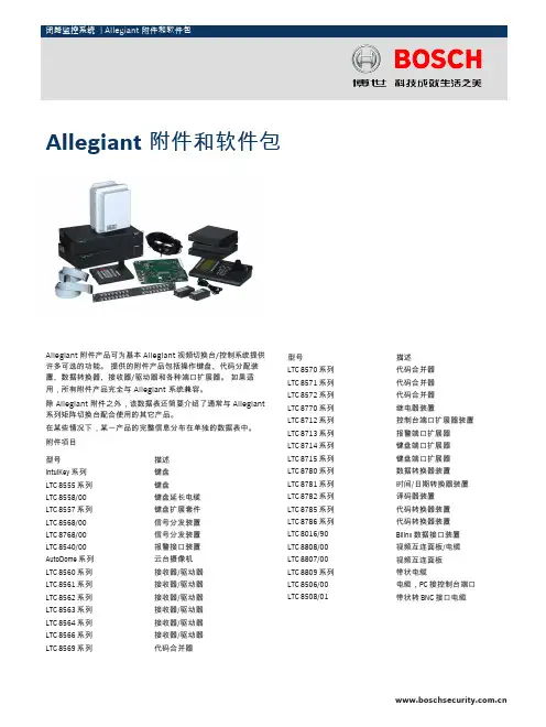
Allegiant 附件产品可为基本 Allegiant 视频切换台/控制系统提供许多可选的功能。
提供的附件产品包括操作键盘、代码分配装置、数据转换器、接收器/驱动器和各种端口扩展器。
如果适用,所有附件产品完全与 Allegiant 系统兼容。
除 Allegiant 附件之外,该数据表还简要介绍了通常与 Allegiant 系列矩阵切换台配合使用的其它产品。
在某些情况下,某一产品的完整信息分布在单独的数据表中。
附件项目型号描述IntuiKey 系列键盘LTC 8555 系列键盘LTC 8558/00键盘延长电缆LTC 8557 系列键盘扩展套件LTC 8568/00信号分发装置LTC 8768/00信号分发装置LTC 8540/00报警接口装置AutoDome 系列云台摄像机LTC 8560 系列接收器/驱动器LTC 8561 系列接收器/驱动器LTC 8562 系列接收器/驱动器LTC 8563 系列接收器/驱动器LTC 8564 系列接收器/驱动器LTC 8566 系列接收器/驱动器LTC 8569 系列代码合并器型号描述LTC 8570 系列代码合并器LTC 8571 系列代码合并器LTC 8572 系列代码合并器LTC 8770 系列继电器装置LTC 8712 系列控制台端口扩展器装置LTC 8713 系列报警端口扩展器LTC 8714 系列键盘端口扩展器LTC 8715 系列键盘端口扩展器LTC 8780 系列数据转换器装置LTC 8781 系列时间/日期转换器装置LTC 8782 系列译码器装置LTC 8785 系列代码转换器装置LTC 8786 系列代码转换器装置LTC 8016/90Bilinx 数据接口装置LTC 8808/00视频互连面板/电缆LTC 8807/00视频互连面板LTC 8809 系列带状电缆LTC 8506/00电缆,PC接控制台端口LTC 8508/01带状转 BNC 接口电缆Allegiant 附件和软件包2基于 Windows®的软件包型号应用LTC 8059/00主控软件LTC 8850/00图形用户界面ADIM DVR 集成软件SFT-INTSRV Allegiant 集成软件证书与认可电磁兼容性 (EMC)符合 FCC 第 15 部分、ICES-003 和 CE 规章要求产品安全符合 CE 法规、UL、CSA、EN 和 IEC 标准技术规格通用规格环境注:以下规格适用于所有电子硬件产品,除非相应附件部分中特别指明。
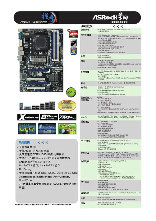
產品摘要內存擴充插槽音效局域网后背板輸入/輸出接口板載接口BIOS 特性SATA3支持光盤規格更改時恕不預先通知 品牌和產品名稱歸各自公司所有。
不保證任何配置与產品實物規格相同。
- 全固态电容设计- 支持AM3+, 八核心处理器- 支持双通道DDR3 1866(超频)内存技术- 支持ATI TM 4路CrossFireX TM 交叉火力技术和 CrossFireX TM 交叉火力技术- 5 x SATA3 接口, 1 x eSATA3 接口- Dr. Debug- 支持涡轮增压极速 USB, AXTU, UEFI, XFast USB , Instant Boot, Instant Flash, APP Charger, SmartView- 7.1声道高保真音频 (Realtek ALC887 音频编码解 码器)- 南桥: AMD SB850- 双通道DDR3内存技术- 4 x DDR3 内存插槽- 支持DDR3 1866(超频)/1800(超频)/1600(超频)/1333/1066/800 non-ECC, un-buffered内存- 系统内存最大容量: 32GB- 2 x PCI Express 2.0 x16 插槽 (PCIE2 @ x16 模式; PCIE3 @ x4 模式)- 1 x PCI Express 2.0 x 1 插槽- 2 x PCI插槽- 支持ATI 4路CrossFireX 交叉火力技术和CrossFireX 交叉 火力技术- 7.1声道高保真音频 (Realtek ALC887 音频编码解码器) - PCIE x 1 千兆网卡10/100/1000 Mb/s - Realtek RTL8111E- 支持网络唤醒功能(Wake-On-LAN)- 支持网线侦测- 支持 Energy Efficient Ethernet 802.3azI/O面板- 1 x PS/2 鼠标接口- 1 x PS/2 键盘接口- 1 x 串行端口:COM1- 1 x 光纤SPDIF数字音频输出端口- 8 x USB 2.0接口- 1 x eSATA3接口- 1 x RJ-45 网卡接口LED指示灯(ACT/LINK LED和SPEED LED)- HD音频插孔: 后置喇叭/中置/低音/线性输入/前置喇叭/麦克风- 5 x SATA3 接口(6.0 Gb/s),支持RAID (RAID 0,RAID 1, RAID 0+1和 RAID 5),NCQ,AHCI和“热插拔”功能- 5 x SATA3 接口(6.0 Gb/s)- 1 x 红外线接针- 1 x HDMI_SPDIF接针- 1 x 电源 LED 接针- CPU/机箱/电源风扇接口- 24针ATX电源接口- 8针12V电源接口- 前面板音频接口- 3组USB 2.0针状接头 (支持6个USB 2.0接口)- 1 x Dr. Debug (7 段式调试 LED指示灯)- 支持图形界面的 32Mb AMI UEFI Legal BIOS - 支持“即插即用”- 符合ACPI 1.1,支持唤醒与自动开机(Wake Up Events)- 支持免跳线- 支持SMBIOS 2.3.1- DRAM 电压多功能调节器- 驱动程序,应用软件,杀毒软件(试用版),AMD OverDrive™ 工具,AMD Fusion,AMD Fusion 媒体 浏览器,华擎软件套装(CyberLink DVD 套件 - OEM 与试 用版; Creative Sound Blaster X-Fi MB - 试用版)獨家功能- ASRock Extreme Tuning Utility (AXTU)- Instant Boot- 华擎 Instant Flash - 华擎 AIWICore CPU Ready 8CPU ReadyCPU Supports AM3+CPUSupports中文化BIOS华擎网吧专用主板全部选用全固态电容,提供稳定持久的供电能力。

致铭主板黑钻A870-G黑钻系列主机板V1.1致铭官方网站:致铭客户邮箱:E-mail:*****************致铭技术热线:*************安全指导1.务必请仔细通读本安全指导。
2.务必请妥善保管本手册,以备将来参考。
3.请保持本设备的干燥。
4.在使用前,宜将本设备至于稳固的平面上。
5.机箱的开口缝槽是用于通风,避免机箱内的部件过热。
请勿将此类开口掩盖或堵塞。
6.在将本设备与电源连接前,请确认电源电压值,将电压调整为110V/220V 。
7.请将电源置于不会被践踏到的地方,并且不要在电源线上堆置任何对象。
8.插拔任何扩展卡或设备模块前,请都将电源线拔下。
9.请留意手册上提到的所有注意和警告事项。
10.不得将任何液体倒入机箱开口的缝槽中,否则会产生严重损坏或电路瘫痪。
11.如果发生以下情况,请找专业人员处理;a.电源线或插头损坏;b.液体渗入机器内;c.机器暴露在潮湿的环境中;d.机器工作不正常或用户不能通过本手册的指导使其正常工作;e.机器跌落或受创;f.机器有明显的破损迹象;12.请不要将本设备置于或保存在温度高于60℃(140℉)的环境下,否则 会对设备造成损害。
致铭主机板用户手册CTHIM MAINBOARD USER ’S MANUAL版权保护声明本手册为致铭科技的专用用户手册,我们非常小心的核对整理,但我们对于本手册的内容不保证完全正确。
同时因为我们的产品一直在持续的改良及更新,内部附图供参考,可能部分细节与实际产品有一点区别,在此手册中的一些规格或者参数都可能会存在过时而不适用的情况,这点致铭科技具有最终解释权。
主机板上的任何标帖请勿擅自撕毁,否则可能会影响到该款产品的质保期限的认定标准。
W ARNINGNever run the processor without the heatsink properly and firmly attached.PERMANENT DAMAGE WILL RESUL T!警告将散热器牢固地安装到处理器上之前,不要运行处理器,过热将永远损坏处理器!商标声明所有的品牌,产品,徽标,商标和公司名称都是属于商标或注册商标各自的拥有者。

目录1 快速入门 (3)1.1 程序界面 (3)1.2 主要菜单项 (3)1.3 工具栏 (8)1.4 状态栏 (8)1.5 分析参数 (9)1.6 高频炉控制参数 (10)1.7 示波器 (11)1.8 分析动态显示 (12)1.9 分析结果 (13)2 操作指南 (14)2.1 基本操作 (14)2.1.1 操作员登录 (14)2.1.2 操作员管理 (14)2.1.3 添加分析方法 (16)2.1.4 标准样品管理 (17)2.1.5 系统参数设置 (18)2.1.6 建立系统工作曲线 (21)2.1.7 编辑功率曲线 (22)2.2 系统校正 (23)2.2.1 校正简介 (23)2.2.2 选择校正样品 (24)2.2.3 校正系统 (24)2.3 样品分析 (25)2.3.1 称取样品 (25)2.3.2 选择分析样品 (26)2.3.3 分析样品 (26)2.3.4 数据处理 (27)2.3.5 数据复算 (27)2.3.6 分析结果数据传输 (28)2.4 原始数据管理 (28)2.4.1 原始数据显示 (28)2.4.2 菜单详解 (28)2.4.3 查询详细信息 (30)2.4.4 显示项目选择……………………………………………………………………………………………错误!未定义书签。
2.4.5 数据过滤 (32)2.4.6 查询备份记录 (33)2.4.7 原始记录报表 (34)2.4.7.1 报表设计 (3)2.4.7.2 报表页面设置 (3)2.4.7.3 设置打印参数 (3)2.4.7.4 打印预览 (3)2.4.7.5 打印报表 (3)2.5 系统工具 (41)2.5.1 系统诊断 (41)2.5.2 修复/压缩数据库 (42)2.5.3 数据库备份 (42)1 快速入门1.1 程序界面系统运行后显示的主界面,包括菜单、工具栏、分析参数、高频率控制参数(*)、分析动态显示、状态栏和分析结果几个部分,对于不同的设备配置其界面也有所区别。

Large VenueSPECIFICATION SHEET3x Brighter Colors 1, and reliable performance — 3LCD, 3-chip technology One measurement of brightness is not enough — look for both high color brightness and high white brightness. The PowerLite Pro Z9870UNL has:Color Brightness: 8700 lumens 2White Brightness: 8700 lumens 2Widescreen performance — native WUXGA (1920 x 1200) resolution supports Full HD for presentations, videos, digital signage and moreSeven optional lenses with lens shift — including short-, wide-, rear- and long-throw lenses designed with a change-out lever for easy installationFlexible installation for an immersive experience in any setting — built-in Curved Edge Blending, Portrait Mode projection, and 360-degree installation Get twice the brightness and power — optional stackable frame makes it easy to install two projectors for unbelievable brightness, plus 3D support Versatile connectivity — supports the latest connectivity options, including HDBaseT™, HDMI™, DVI and 3G-SDIDual-lamp design with lamp select/relay function — get both power savings and projector redundancy; includes an innovative liquid cooling system for added reliabilityPowerLite ®Pro Z9870UNL WUXGA 3LCD ProjectorThe bright, large-venue installation projector withFull HD performance.Projector shown with lens.Lens sold separately.Large VenuePowerLite ® Pro Z9870UNL WUXGA 3LCD ProjectorEPSON, EasyMP and PowerLite are registered trademarks, EPSON Exceed Your Vision is a registered logomark and Better Products for a Better Future is a trademark of Seiko Epson Corporation. PrivateLine is a registered trademark, FineFrame is a trademark and Epson Connection is a service mark of Epson America, Inc. SmartWay is a service mark of the U.S. Environmental Protection Agency. All other product and brand names are trademarks and/or registered trademarks of their respective companies. Epson disclaims any and all rights in these marks. Copyright 2014 Epson America, Inc. Com-SS-Oct-13 CPD-41394 6/14 Epson America, Inc.3840 Kilroy Airport Way, Long Beach, CA 90806Epson Canada Limited185 Renfrew Drive, Markham, Ontario L3R 6G3 www.epson.caInterfacesWireless LAN port: 802.11 b/g/n (optional – module sold separately)SpecificationsProjection System High-aperture Epson ®3-chip, 3LCD technologyProjection Method Front/rear/ceiling mountLCD Driving Method Epson Poly-silicon TFT Active Matrix Pixel Number 2,304,000 pixels x 3LCDs Color Brightness 2Color Light Output: 8700 lumens White Brightness 2White Light Output: 8700 lumensAspect Ratio Native 16:10, (supports 4:3, 16:9, 5:4)Native Resolution WUXGA (1920 x 1200)Contrast Ratio (Normal, Dynamic Mode) Up to 15,000:1Color Reproduction 1.07 billion colors Lamp TypeNormal:380 W x 2 UHE Portrait:304 W x 2 UHE Lamp Life 3Normal:Up to 4000 hours (ECO Mode)Up to 2500 hours (Normal Mode)Portrait:Up to 1000 hours (Normal Mode)Brightness Uniformity (typical) 90%Pixel Arrangement Cross stripeProjection LensScreen Throw Ratio Range 1.74 – 2.82 (standard lens)Size (projected distance) 60" – 500"Type Powered zoom/focusF-number 1.65 – 2.51 (standard lens), lens not included Focal Length 36 mm – 57.35 mm (standard lens)Zoom Ratio Optical zoom 1 – 1.61 (standard lens)Lens Shift (powered)Vertical: ±60%Horizontal: ±18%Keystone CorrectionVertical: -30 degrees to +30 degrees Horizontal: -30 degrees to +30 degreesVideoVideo StandardsAnalog: NTSC/NTSC4.43/PAL/M-PAL/N-PAL/PAL60/SECAM HDMI: 480i/576i/480p/576p/720p/1080i/1080p DVI-D: 480i/576i/480p/576p/720p/1080i/1080p SD-SDI: 480i/576iHD-SDI: 720p/1080i/1080p@303G-SDI: 1080p@60SDI: 480i/576iVideo Processing 3D Y/C separation, 3D noise reduction, mosquito noise reductionDCDi ® – Directional Correlational DeinterlacingMotion-compensated Interlace-Progressive conversion (2:2, 3:2 film detection)Super ResolutionFineFrame™ interpolation 8:8 Pull-down processing Closed captioningNetworkingConnectivityWired: Integrated 100 MbpsWireless Security: WPA-PSK (TKIP/AES) / WPA2-PSK (TKIP/AES)E-mail Notification Via network Message Broadcasting SNMP Web Control Secure HTTPNetworking (continued)Remote Control and ManagementEasyMP ® Monitor, network projection, multi-projection, AMX ® Device Discovery, Crestron ® Integrated Partner and Crestron RoomView ®, Extron ® IP Link and XTP , PJLinkOther FeaturesOperating Temperature32 ° to 122 °F (0 ° to 50 °C) — Normal32 ° to 104 °F (0 ° to 40 °C) — Above 4900 feetPower Supply Voltage 100 – 240 V ±10%, 50/60 Hz AC Power Consumption 821 W (ECO Mode)995 W (Normal Mode)2.7 W standby (Communication on)0.26 W standby (Communication off)Fan Noise35 dB (ECO Mode)48 dB (Normal Mode)Security Kensington ®-style lock provision, anchor (metal) bar for security lock or cable, handles attached to body for cable wrapDimensions (W x D x H)Including Feet (with standard lens) 29.17" x 21.01" x 10.04"Excluding Feet (with standard lens) 29.17" x 21.02" x 7.76"Weight 58 lb with standard lensRemote ControlFeatures Brightness, contrast, tint, saturation, sharpness, input signal, sync, tracking, position, zoom, focus, lens shift, shutter, ID, source search, split screen Operating AngleFront:Right/left ± 60 degreesUpper/lower -45 to +15 degrees Rear:Right/left ± 60 degreesUpper/lower -40 to +15 degrees Operating Distance 98 ftECO FeaturesRoHS compliant Recyclable product 4Epson America, Inc. is a SmartWay SM Transport Partner 5SupportThe Epson Connection SMPre-sales support U.S. and Canada 800-463-7766Internet website Projector ProgramsThree-year projector limited warranty, 90-day limited lamp warranty, Epson Road Service Program and PrivateLine ®dedicated toll-free support (U.S. and Canada only)What’s in the BoxPowerLite Pro Z9870UNL projector, power cable, computer cable, projector remote control, batteries, user manual CD, Quick Setup Sheet, monitor and control CDOrdering Information Product Name Product Code PowerLite Pro Z9870UNL projectorV11H611920AccessoriesProduct CodeStandard zoom lens (ELPLS04) V12H004S04Long-throw zoom lens (ELPLL07)V12H004L07Middle-throw zoom lens 1 (ELPLM06)V12H004M06Middle-throw zoom lens 2 (ELPLM07)V12H004M07Rear-projection wide lens (ELPLR04)V12H004R04Wide zoom lens (ELPLW04)V12H004W04Short-throw zoom lens (ELPLU02) V12H004U02Mount Installation frame (ELPMB44) V12H681010Flush ceiling mount bracketV12H003B25Mount bracket with extended pipe V12H003B26False ceiling plate kit ELPMBP02Wireless LAN module V12H418P12Kensington security lockELPSL01Hardware remote control cable set V12H005C28Replacement remote control2157388Replacement lamp single (ELPLP81)V13H010L81Dual lamp kit (lamp x 2) (ELPLP82)V13H010L82Replacement portrait lamp single (ELPLP83) V13H010L83Dual lamp kit (lamp x 2) (ELPLP84)V13H010L84Replacement air filter set (ELPAF46)V13H134A461Compared to leading 1-chip DLP business and education projectors based on NPD data, July 2011 through June 2012. Color brightness (color light output) measured in accordance with IDMS 15.4. Color brightness will vary depending on usage conditions.2Color brightness (color light output) and white brightness (white light output) will vary depending on usage conditions. Color light output measured in accordance with IDMS 15.4; white light output measured in accordance with ISO 21118.3Lamp life will vary depending upon mode selected, environmental conditions and usage. Lamp brightness decreases over time.4See our website for convenient and reasonable recycling options at /recycle5SmartWay is an innovative partnership of the U.S. Environmental Protection Agency that reduces greenhouse gases and other air pollutants and improves fuel ef ciency.DVI-DRS-232CLAN HDBaseTHDMIVideoS-VideoComputer RemoteMonitor Out BNCServicePowerSDIWireless LAN Port。
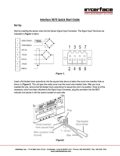
Interface 9870 Quick Start GuideSet Up:Start by inserting the sensor wires into the Sensor Signal Input Connector. The Signal Input Terminals are indicated in (Figure 1) below:(Figure 1)Insert a flat bladed micro screwdriver into the square hole above or below the round wire insertion hole as shown in (Figure 2). This will open the metal cover over the round wire insertion hole. After you have inserted the wire, remove the flat bladed micro screwdriver to secure the wire in its position. Once all of the necessary wires have been attached to the Signal Input Connector, plug the connector into the 9870 indicator and secure it with the screws located on each side.(Figure2)Plug the supplied DC power adaptor into the 9870 DC input, then plug the DC power adaptor into a standard wall socket. You will see the 9870 Standard Home Screen appear on the display.Remote Sense / TEDS:If you are using a six-wire configuration TEDS enabled load cell or SENS enabled loadcell, you will need to adjust the Remote Sense/TEDS parameter. If you are using a four-wire configuration load cell without TEDS or SENS, skip ahead to the Calibration section.To begin Remote Sense / TEDS Enabling from the Standard Home Screen, press the Function button. This will bring you to the Function Menu:From the Function Menu, use the Arrow buttons to highlight Calibration, then press the Enter button. This will bring you to the Calibration Menu:From the Calibration Menu use the Arrow buttons to highlight Remote Sense / TEDS, then press the Enter button. This will take you to the Remote Sense / TEDS Menu:At the Remote Sense / TEDS Menu, use the Arrow buttons to select the appropriate option depending on the type of load cell you are using. For this example, we will choose SENS enabled. If you are using a TEDS enabled load cell, then choose TEDS enabled. Once you have made a selection, press the Enter button. The option you have selected will be highlighted in Green. Press the Enter button again to confirm your selection:This will bring you back to the calibration menu, the Remote Sense / TEDS parameter has been set. Press the Escape button two times to return to the Standard Home Screen:If you are using a TEDS enabled load cell, skip ahead to the Digital Zero section. Otherwise, proceed with Calibration.Calibration:From the Standard Home Screen, press the Function button. This will bring you to the Function Menu:From the Function Menu use the Arrow buttons to highlight Calibration, then press the Enter button:From the Calibration Menu use the Arrow buttons to highlight Equivalent Input Calibration, then press the Enter button:Use the Arrow buttons to select the Excitation Voltage indicated on the sensors corresponding Calibration Certification, then press the Enter button. The selected Excitation Voltage will be highlighted Green. Press the Enter button again to confirm the selected Excitation Voltage:This will bring you to the Rated Output and Rated Capacity parameters. The Rated Output will be highlighted in White. Use the Arrow buttons to select the Rated Output indicated on the sensors corresponding Calibration Certification, then press the Enter button:The Rated Capacity will now be highlighted in White. Use the Arrow buttons to select the Rated Capacity indicated on the sensors corresponding Calibration Certification, then press the Enter button:The Rated Output and the Rated Capacity are now highlighted in Green. Press the Enter button again to confirm the Rated Output and Rated Capacity values:This will bring you to the Zero Balancing function. For the purpose of this Quick Start guide, it will not be necessary to execute the Zero Balancing function. For further information on the Zero Balancing function, see (Page 37) of the Interface 9870 User Manual. To proceed, use the Arrow buttons to highlight Skip and then press the Enter button:Next you will see the D/A Output Mode parameter. The Analog Output can be set to Voltage or Current depending on the requirements of the application. For this example, we will select Voltage. Use the Arrow buttons to highlight Voltage and then press the Enter button. Voltage will be highlighted in Green. Press the Enter button again to confirm the D/A Output Mode parameter:This will bring you to the D/A Max. Voltage parameter. For this example, we will set the D/A Max. Voltage to 10v. Use the Arrow buttons to input 10v, then press the Enter button. 10v will be highlighted in Green, press the Enter button again to confirm the D/A Max Voltage parameter:Next select the desired Engineering Units from the Select EU menu. Use the Arrow buttons to highlight the appropriate Engineering Units, then press the Enter button. The selection will be highlighted in Green, press the Enter button again to confirm the selected Engineering Units:After you have confirmed the Engineering Units, you will see the Cal. Value Lock parameter. This can be used to lock the Calibration Value if necessary. For this example, it will not be necessary to lock the Calibration Value. Use the Arrow buttons to highlight OFF and then press the Enter button. The OFF selection will be highlighted in Green. Press the Enter button again to confirm the selection:This will bring you back to the Function Menu. From the Function Menu, press the Escape button to return to the Standard Home Screen:The load cell is now calibrated, proceed to Digital Zero.Digital Zero:To set Zero from the Standard Home Screen, Hold down the Zero Button. When the Interface 9870 has completed setting Zero, the Zero value will be displayed on the Standard Home Screen:The Interface 9870 is now is now calibrated and ready to use. For more detailed information regarding the full range options and functions available within the Interface 9870, please refer to the Interface 9870 User Manual.。
Model 878Dual-Display Handheld LCR Meterwith Statistical FunctionsThe 878 measures capacitance, resistance, and induc-tance. Components can be measured in the series andparallel mode as desired. The full 4-digit display readsvalues to 9999 on each range. The instrument isautoranging; or manual ranging may be selected. Theinstrument prompts the user when calibration is need-ed, and the dual display shows whether to calibratewith an open or short.Model 875BLow-Ohm LCR MeterThe rugged 875B LCR is a reliable easy-to-use workhorse thatwill measure inductors, resistors and capacitors quickly andaccurately. Utilizing special circuitry, the measurement moreclosely replicates true in-circuit measurements. T en range resist-ance range measures to 0.001 - zero adjust removes leads resist-ance.Model 815Hand-held Component T esterThis handy capacitance meter (0.1 pF-20 mF) and ohmmeter (0.1Ωto 20MΩ) also tests: transistors, beta,diodes, SCRs, LEDs and batteries. Use with TL-8 (shownon page 90) for more effective testing.■Simultaneously displays measuredvalue and Q or dissipation factor■Min/Max average■Relative mode■T olerance mode■T wo selectable testfrequencies (120 Hz,1 kHz)■Precision measurement of verylow resistances■Measures D (dissipation factor)■Unique drop-proofconstruction■Tilt stand■3 1/2 digit extra large (0.8" digit)high contrast LCD display■T ransistor leakage test■Capacitance zero adjustment■Diode and SCR test■LED test■Battery test■5 foot drop-proof heavyduty case66878875B815。
Parts ListDocument Number: Part_List_8000 Updated: 6/17Drop InsN8000, N8000-R, N8100B, N8100-BR, 8100-EF, N8100-FA, N8200, N8200-ST, N8200G, N8600, N8700-D, N8700-DESP , N8700-R, N8800ContentsCap Tube Chart - R134A Refrigerant ..............................................................................................................................................................................28000 Series - Miscellaneous Parts ...................................................................................................................................................................................2N8700-DESP - Common Components ..........................................................................................................................................................................2N8100-FA - Common Components ................................................................................................................................................................................3Condensing Unit Assembly, 115V, 1/5 HP , R134A Narrow .....................................................................................................................................4Condensing Unit Assembly, 115V, 1/5 HP , R404A Narrow .....................................................................................................................................4Condensing Unit Assembly, 230V, 1/5 HP , R404A, Narrow ....................................................................................................................................5Condensing Unit Assembly, 1/4 HP , R404a Low Temp ............................................................................................................................................6Condensing Unit Assembly, 1/4 & 1/3 HP , R134A Narrow .....................................................................................................................................7Condensing Unit Assembly, 1/4 & 1/3 HP , R404A Narrow .....................................................................................................................................8Condensing Unit Assembly, 1/3 HP , R404a Low Temp ............................................................................................................................................9Condensing Unit Assembly, 1/2 HP , R404a Low Temp ..........................................................................................................................................10Condensing Unit Assembly, 1/2 HP , R404A Mid Temp ..........................................................................................................................................11Condensing Unit Assembly, 3/4 HP , R404A ...............................................................................................................................................................12Food Well Assembly With Infinite Control .................................................................................................................................................................13Food Well Assembly With Thermostat control .........................................................................................................................................................14Food Well Assembly With Thermostat Control .. (15)Cap Tube Chart - R134A RefrigerantModel Number Cap Tube Size/LengthN8118B.036ID x 72”N8130B.036ID x 72”N8143B.036ID x 72”N8144-BR.036ID x 72”N8146NB.042ID x 120”N8156B.042ID x 120”N8159-BR.036ID x 72”N8168NB.042ID x 120”N8169B.042ID x 120”N8176-BR.042ID x 120”N8181B.054ID x 110”N8194-BR.042ID x 120”8000 Series - Miscellaneous Parts25”N8700-DESP - Common ComponentsCommon and 220V parts used in export series N8700-DESP-E.12Key Description Part Number Note 1Control, 500W Food Well21953192Food Well/Heatpad, 208V-500W3234798[A] 2Food Well/Heatpad, 240V-500W3234950[A] Food Well/Heatpad, 208V-500W, Without Drain3234951[A] NOTE: [A] When replacing the well not to apply pressure directly to the pad.2 Updated: 6/17N8100-FA - Common ComponentsKey DescriptionPart Number Per ModelN8131-FA2-PANN8144-FA3-PANN8157-FA4-PANN8169-FA5-PANN8182-FA6-PAN1Upright diffuser226-0V3-0030226-0V3-0031226-0V3-0032226-0V3-0033226-0V3-0034 2Air deflector226-A9L-0030226-A9L-0031226-A9L-0032226-A9L-0033226-A9L-0034 3Coil351008635100863510086351008635100864Expansion valve351627335162733516273351627335162735Coil assembly cover019-0V0-0030019-0V0-0038019-0V0-0032019-0V0-0033019-0V0-0034 6Fan assembly cover226-0V1-0030226-0V1-0031226-0V1-0032226-0V1-0033226-0V1-0034 7Adapter bar243-AB0-0001243-AB0-0001243-AB0-0001243-AB0-0001243-AB0-0001 8Perforated pan clip270-0V5-0030270-0V5-0031270-0V5-0032270-0V5-0033270-0V5-0034 9Black airflow extrusion316-991-0030316-991-0031316-991-0032316-991-0033316-991-0034 10Cover support bracket226-0V2-0030226-0V2-0030226-0V2-0030226-0V2-0030226-0V2-0030 11Fan guard3516173351617335161733516173351617312Blade, fan, 5.56, CCW, clear3516172351617235161723516172351617213Fan motor2162691216269121626912162691216269114Fan bracket031-264-0000031-264-0000031-264-0000031-264-0000031-264-0000 15Plexiglas end cap091-0XL-0030091-0XL-0030091-0XL-0030091-0XL-0030091-0XL-0030 16S/S thumb screw9321541932154193215419321541932154117Cond. Unit000-BN5-006A000-BN5-0035000-BN5-0035000-BN5-0036000-BN5-0036 Timer21943452194345219434521943452194345 Pressure Control21939272193927219392721939272193927 Rocker switch21901542190154219015421901542190154Updated: 6/17 34 Updated: 6/17Condensing Unit Assembly, 115V, 1/5 HP , R134A NarrowUsed in production prior to 7-11-16.Used in models N8118B, N8130B, N8143B, N8144-BR, N8146NB and N8168NB.Key DescriptionPart Number 1Harness, wire, power cord, 810021833002Compressor, 1/5 h.p.,115v/60hz 35266943Cold Control35160544Compressor stand024-ADB-00405Bracket, fan motor, blower coil 031-264-00006Blade, fan, 5.56, CCW, clear35161727Motor, fan, 115v, 50/60, UPPCO/bay 21626918Fan baffle026-ANM-00309Coil, condenser, 9 x 10, R-134a, 81003516067Filter dryer, double 1/4”OD inlet3516230Condensing Unit Assembly, 115V, 1/5 HP , R404A NarrowUsed in production after 7-11-16.Used in models N8118B, N8130B, N8143B, N8144-BR and N8146NB.Key DescriptionPart Number 1Harness, wire, power cord, 810021833002Compressor, R404A, 1/5 h.p.,115v/60hz 35269963Cold Control35160544Compressor stand024-ADB-00465Bracket, fan motor, blower coil 031-264-00006Blade, fan, 5.56, CCW, clear35161727Motor, fan, 115v, 50/60, UPPCO/bay 21626918Fan baffle026-ANM-00309Coil, condenser, 9 x 10, R-134a, 81003516067Filter dryer, double 1/4”OD inlet3516230Condensing Unit Assembly, 230V, 1/5 HP, R404A, NarrowUsed in export models N8118B-E, N8130B-E, N8143B-E, N8146NB-E, N8168NB-EKey Description Part Number-Assembly, 1/5 Condensing Unit000-BN5-003I1Fan, Axial, 5.5.", 230V21600292Guard, Fan, 6.0"21600303Shroud, Condenser Coil026-C58-00374Compressor, 1/5HP, 220/50, TL4CL35269945Start Capacitor3516451 Compressor, Relay3516452 6Filter Dryer35163227Condensate Pan039-231-00308Condenser Coil3516454-15 Amp switch, 220V2194400Updated: 6/17 5Condensing Unit Assembly, 1/4 HP, R404a Low TempUsed in series 8100-EFN, series N8200-ST, models 8118-EF, 8132-EF, 8145-EF,8159-EF, 8172-EF,models N8131-FA, N8231, N8231G, N8245, N8245G, N8259, N8273, N8630, N8643, N8656 and N8669.Common and 220V parts used in export series 8100-EF-E, series 8100-EFN-E, models N8231-E, N8231G-E, N8245-E,N8245G-E, N8259-E and N8273-E.Key Description Part Number Condensing Unit Assembly, 115V000-BN5-006ACondensing Unit Assembly, 220V/50Hz000-BN5-006D 1Blade, Fan, 7.253516480 Motor, Fan, 9W, 115V, CW2162717Motor, Fan, 9W, 220V, Unit Bearing2162720 2Guard, Fan, 7.252160020 3Shroud, Condenser Coil026-C58-0037 4Compressor, NF5.5CLX, 115V/60Hz3526999 Compressor 220/50Hz3527013 5Capacitor, Start 280MFD2194787 Compressor relay and overload, NF5.5CLX3516444 6Filter-dryer, (2) inlet .25”3516322 7Pan, condensate075-231-0030 8Condenser Coil3516454Miscellaneous Parts Not Included in Condensing Unit15 Amp switch, 120V219409915 Amp switch, 220V2194400 Cord/plug assembly, 120V2183348 Cord/plug assembly, 220V Varies per destination Expansion valve, 120V3516225 Expansion valve, 220V MCP00140 Clip, sensing bulb35165956 Updated: 6/17Updated: 6/17 7Condensing Unit Assembly, 1/4 & 1/3 HP , R134A NarrowCommon and 220V parts used in export models N8156B-E and N8169B-E.Used in 115V production prior to 7-11-16. Used in models N8156B, N8159-BR, N8169B, N8176-BR, N8181B and N8194-BR.21Key DescriptionPart Number 1Harness, wire, power cord21833002Compressor, 1/4 h.p.,115v/60hz, N8156B, N8159-BR, N8169B, N8176-BR 3526695Compressor, 1/4 h.p., 220v/50hz3526719Compressor, 1/3 h.p., 115/60, R134A, N8181B, N8194-BR 35267033Cold control35160544Stand, compressor024-ADB-00415Fan assembly, condenser, 8” blade, 115V 2194013Fan assembly, condenser, 8” blade, 220V 21626896Baffle, fan026-ANM-00337Coil, condenser, 9x10, R134A 351606715 Amp switch, 220V2194400Filter dryer, double 1/4”OD inlet35162308 Updated: 6/17Condensing Unit Assembly, 1/4 & 1/3 HP , R404A NarrowUsed in production after 7-11-16. Used in models N8156B, N8159-BR, N8168NB, N8169B, N8176-BR, N8181B and N8194-BR.21Key DescriptionPart Number 1Harness, wire, power cord21833002Compressor, 1/4 h.p.,R404A, 115v/60hz, N8156B, N8159-BR, N8168NB, N8169B 3527000Compressor, 1/3 h.p., 115/60hz, N8176-BR, N8181B, N8194-BR 35267033Cold control35160544Stand, compressor024-ADB-00465Blade, Fan, 5.56”, CCW, Clear 3516172Motor, Fan, 120V, 50/6021626916Baffle, fan026-ANM-00307Coil, condenser, 9x10, R134A 3516067Filter dryer, double 1/4”OD inlet3516230Condensing Unit Assembly, 1/3 HP, R404a Low TempUsed in models 8186-EF, N8259G, N8287 and N8681.Common and 220V parts used in export models N8259G-E and N8287-E.Key Description Part Number Note Condensing Unit Assembly, 115V000-BN5-006BCondensing Unit Assembly, 220V/50Hz000-BN5-006C 1Blade, Fan, 7.253516480 Motor, Fan, 9W, 115V, CW2162717Motor, Fan, 9W, 230V, Unit Bearing2162720 2Guard, Fan, 7.2521600203Shroud, Condenser Coil026-C58-00374Compressor, NF7.0. 115V/60Hz3527000 Compressor, 220V/50Hz3527012 5Capacitor, Start 320MFD2194788 Compressor relay and overload, NF7CLX3516438 6High pressure switch35163247Filter-dryer, (2) inlet .25”35163228Receiver tank3516658[A] 9Pan, condensate075-231-003010Condenser Coil3516454NOTE: [A] Re-piping may be required for installation.Miscellaneous Parts Not Included in Condensing Unit15 Amp switch, 120V219409915 Amp switch, 220V2194400Cord/plug assembly, 120V2183348Cord/plug assembly, 220V Varies per destination Expansion valve, 120V3516225 Expansion valve, 220V MCP00140Updated: 6/17 9Condensing Unit Assembly, 1/2 HP, R404a Low TempUsed in model N8273G.Key Description Part Number Condensing Unit Assembly, 115V000-BN5-0033 Condensing Unit Assembly, 220V/50Hz000-BN5-003N 1Shroud, 1/2 HP Condenser Coil026-C58-0031 2Blade, Fan, 9.00”, 5-pedal3516554 3Guard, Fan, Condenser, Upright2160019 4Motor, Fan, 16W, 115V2162716 Motor, Fan 16W, 230V2162721 5High Pressure Switch3516324 6Compressor, SC12CLX.2,115V/60Hz3527001 Compressor, 220V/50Hz3527011 7Filter-dryer, (2) inlet .25”3516322 8Capacitor, Start 240MFD2194789 Compressor relay, SC12CLX.23516441 9Receiver, used on models built after 9-9-153516659 Receiver, used on models built before 9-9-153516459 10Condenser Coil3516455Miscellaneous Parts Not Included in Condensing Unit Expansion valve3516225 15 Amp switch, 120V2194099 15 Amp switch, 220V2194400 Cord/plug assembly218334810 Updated: 6/17Condensing Unit Assembly, 1/2 HP, R404A Mid TempUsed in models N8144-FA and N8157-FA.Key Description Part Number Condensing Unit Assembly000-BN5-0035 1Shroud, 1/2 HP condenser coil026-C58-00312Blade, fan 9.00”, 5 pedal35165543Guard, fan, condenser, upright21600194Motor, fan, 16W, 115V21627165Capacitor, start, assembly35164626Compressor, SC12MLX, 115V/60Hz35270267High pressure switch35163318Filter dryer, (2) inlet, .25”35163229Receiver, used on models built after 9-9-153516659 Receiver, used on models built before 9-9-153516459 10Pan, condensate075-231-003111Coil, 1/2 HP condensing3516455Updated: 6/17 11Condensing Unit Assembly, 3/4 HP, R404AUsed in models N8169-FA and N8182-FA.Key Description Part Number Note Condensing Unit Assembly000-BN5-0036 1Shroud, 3/4 HP condenser coil026-C58-00322Guard, fan, condenser, upright21600193Capacitor, start, run, assembly35164424Compressor, SC18MLX, 115V/60Hz35270215Filter dryer, (2) inlet, .25”35163226Tank, receiver3516657[A] 7Coil, condenser, 3/4 HP 3516456 Pan, condensate075-231-0031Blade, fan 25º, 10”, CW, upright3516433Motor, fan, 16W, 115V2162716NOTE: [A] Re-piping may be required for installation.12 Updated: 6/17Food Well Assembly With Infinite ControlUsed in models N8700D, N8700N, N8700ND and N8700R.Common and 220V parts used in export series N8700D-E.Key Description Part Number1Insulation, fiberglass, 9” x 48”34347032Thermostat, non-adjustable, 480˚F21943353Bottom cover026-103-00024Insulation, blanket, 24” wide34346635Plate, deflector, DFW, with or without drain026-061-00016Element, heating, 208/230v, 1000/1222w2194007 Element, heating, 120v2194006 7Well, hot food, with drain000-BQ9-Z0001 Well, hot food, without drain000-BQ9-Z0000Knob, infinite control3234557Control, infinite, 240v, 14a2194110KTControl, infinite, 120v2194107KTUpdated: 6/17 13Food Well Assembly With Thermostat controlUsed in model N8600.Key Description Part Number 1Immersion heater 120V, 1Ph2194075 Immersion heater 240V 1Ph 5KW 2193974 2Box, control, galv, 8600 series026-AO6-0041 3Front, collar, mounting, 8600372-ANQ-003D 4Switch, 3 position, 30Amp2193979 5Cover, control box, 8700 series372-ANS-0001 6Light, pilot, 125V, red2194190 7Thermostat, electric (heated)2194202 8Knob, thermostat control (heated)3234556 9Contactor, 2 Pole, 120V2194974 10Temperature control (cold)351605414 Updated: 6/17Food Well Assembly With Thermostat ControlUsed in models N8831, N8859, N8873 and N8887.Common and 220V parts used in export series N8800-E.Key Description Part Number1Knob, thermostat control32345562Thermostat 30A, N8873. N88872193984 Thermostat, 25A, N8831, N8845, N88592194012 3Element, heating, 208/230v, 1000/1222w2194007 Element, heating, 120v, 1000w2194006 4Plate, deflector, DFW, with drain026-061-0001 Insulation, fiberglass, 1” thick3434704Insulation, fiberfrax, 1” thick3434664Updated: 6/17 15DELFIELD980 SOUTH ISABELLA ROAD, MOUNT PLEASANT, MI 48858800-733-8821Welbilt pro vides the world’s top chefs, and premier chain operators or growing independents with industry leading equipment and solutions.Our cutting-edge designs and lean manufacturing tactics are powered by deep knowledge, operator insights, and culinary expertise.All of our pr oducts are backed by KitchenCare® – our aftermarket, repair, and parts service.。
GUIDE DE DÉMARRAGE ET DE SÉCURITÉLAVE-VAISSELLESHEM78****, SHE878****TABLE DES MATIÈRESCONSIGNES DE SÉCURITÉ . . . . . . . . . . . . . . . . .2MISE EN MARCHE . . . . . . . . . . . . . . . . . . . . . . . . .4CYCLES ET OPTIONS . . . . . . . . . . . . . . . . . . . . . .6 CONSEILS D’ENTRETIEN . . . . . . . . . . . . . . . . . . .8DÉCLARATION DE LA GARANTIE . . . . . . . . . .10121901 MAIN STREET, SUITE 600 IRVINE, CA 92614 // © 2020 B S H H O M E A P P L I A N C E S C O R P O R ATI O N9001545148 0007 640A M OEn aucun cas, Bosch ne sera tenue responsable de dommages survenus à la propriété environnantes, incluant les armoires, les planchers, les plafonds et les autres objets ou structures situés autour du produit . Également exclus de la garantie sont les Produits dont les numéros de série ont été modifiés, effacés ou enlevés;les demandes deréparations pour enseigner le fonctionnement du Produit ou les visites où il n’y a aucun problème avec le produit; la correction de problèmes d’installation (le consommateur est seul responsable pour toute structure et tout réglage du Produit, incluant l’électric-ité, la plomberie et les autres raccordements nécessaires, pour une fondation / plancher approprié[e], et pour toute modification incluant, sans limitation, armoires, murs,planchers, tablettes, etc .) et le réenclenchement de disjoncteurs ou le remplacement de fusibles .DANS LA MESURE AUTORISÉE PAR LOI, LA PRÉSENTE GARANTIE PRÉCISE LES RECOURS EXCLUSIFS DONT VOUS DISPOSEZ À L’ÉGARD DU PRODUIT, QUE LADEMANDE SOIT FONDÉE SUR UN CONTRAT OU DÉLIT (Y COMPRIS RESPONSABILITÉ ABSOLUE OU NÉGLIGENCE) OU AUTRE . LA PRÉSENTE GARANTIE REMPLACETOUTES LES AUTRES GARANTIES, EXPRESSES OU IMPLICITES . TOUTES GARANTIES IMPLICITES AUX TERMES DE LA LOI, QUE SE SOIT LES GARANTIES DE QUALITÉ MARCHANDE OU D’APTITUDE À UN USAGE PARTICULIER, OU AUTRES, SONTLIMITÉES DANS LE TEMPS À LA DURÉE DE CETTE GARANTIE LIMITÉE EXPRESSE . LE FABRICANT NE SERA EN AUCUN CAS RESPONSABLE DE DOMMAGES CONSÉCUTIFS, SPÉCIAUX, ACCESSOIRES, INDIRECTS OU DE « PERTES COMMERCIALES » ET / OU DE DOMMAGES PUNITIFS, DE PERTES OU DE DÉPENSES, Y COMPRIS SANS S’Y LIMITER, ABSENCE DU TRAVAIL, FRAIS D’HÔTEL ET / OU FRAIS DE RESTAURANT, FRAIS DEREMANIEMENT EN EXCÉDENT DES DOMMAGES DIRECTS QUI SONT DÉFINITIVEMENT CAUSÉS EXCLUSIVEMENT PAR BOSCH, OU AUTREMENT . CETAINS ÉTATSN’AUTORISENT PAS L’EXCLUSION OU LA LIMITATION DE DOMMAGESACCESSOIRES OU CONSÉCUTIFS, ET CERTAINS ÉTATS N’AUTORISENT PAS LA LIMITATION DE LA DURÉE DES GARANTIES IMPLICITES . PAR CONSÉQUENT, LES EXCLUSIONS OU LES LIMITES SUSMENTIONNÉES POURRAIENT NE PAS VOUS CONCERNER . LA PRÉSENTE GARANTIE VOUS DONNE DES DROITS PRÉCIS RECONNUS PAR LA LOI ET VOUS POUVEZ ÉGALEMENT AVOIR D’AUTRES DROITS QUI VARIENT D’UN ÉTAT À L’AUTRE .Aucune tentative de modifier, changer ou amender la présente garantie ne peut être valide sans le consentement écrit autorisé par un dirigeant de BSH .Comment obtenir une réparation sous garantie :Pour obtenir une réparation sous garantie pour votre produit, communiquez avec le département de service après-vente de Bosch : Appelez 1-800 944-2904 pour planifier une réparation .Avertissement issue de la proposition 65 de l’État de la Californie :Ce produit pourrait contenir un produit chimique reconnu par l’État de laCalifornie comme cancérigène ou ayant des effets nocifs sur la reproduction. Par conséquent, l’emballage de votre produit pourrait porter l’étiquette suivante, com-me requis par la Californie :。
w w w .n a v m a n .c omIndustry CanadaOperation is subject to the following two conditions: (1) this device may not cause interference, and (2) this device must accept any interference, including interference that may cause undesired operation of the device.Navman VHF 7110 Quick Start GuideIt is the owner’s sole responsibility to install and use the instrument in such amanner that will not cause accidents, personal injury or property damage.Navman New Zealand disclaims all liability for any use of this product in a way that may cause accidents, damage or that may violate the law.Governing Language: This statement, any instruction manuals, user guides andother information relating to the product (Documentation) may be translated to, or has been translated from, another language (Translation). In the event of anyconflict between any Translation of Documentation, the English language version of the Documentation will be the official version of the Documentation.This manual represents the Navman VHF 7110 at the time of printing. Navman New Zealand reserves the right to make changes to specifications without notice.Copyright © Navman New Zealand. All rights reserved. NAVMAN is a registeredtrademark of Navman New Zealand.Please check out your model. There are slight variations in the keys and somefeatures are not available on every model.This manual relates to the following models:• VHF 7110US• VHF 7110EUThis Quick Start Guide and Installation Supplement for the VHF 7110 is to be used in conjunction with the Navman VHF 7100 Owner’s Manual.For further information on these and other options, including radio setup andDSC options, troubleshooting, and channel charts, refer to the Navman VHF 7100 Owner’s Manual.Navman VHF 7110 Installation SupplementThis Installation Supplement is designed to be read with the Navman VHF RADIOINSTALLATION SHEET for 7000, 7100US, 7200US, 7100EU, 7200EU. It provides additional information that is specific to your VHF 7110 radio.12345678••••••InstallationBefore doing any cutting or drilling, check that:• The intended location for the handset wallplate has reasonable access at the rear so that the 10m connection cable can be easily installed and accessed.• The 10m connection cable comfortably reaches from the base unit to the intended location for the handset wallplate.• The intended route for the 10m connection cable allows it to be secured to a bulkhead (or similar) along its length.1. Install the base unit and the microphone bulkhead mount as described in the Navman VHFRADIO INSTALLATION SHEET for 7000, 7100US, 7200US, 7100EU, 7200EU.2. Drill the 25.4mm (1”)hole through the bulkhead at your chosen location.3. Install the handset wallplate components in the order shown in the picture. Finger tighten thelocking nut on the 3m handset cable to make a waterproof connection.4. Install the handset bulkhead mount on the bulkhead, using the screws, nuts and washersprovided.Wiring DetailsIn case a cable is cut accidentally the pinouts are shown here for information only.Do not cut cables intentionally.Connect the Radio Cables - Rear view of base unit1. VHF Antenna connection. (Antenna is not supplied.)2. Combined power and speaker cable. The end of the power cable splits in two: BLACK. Earth. Connect to the (-) NEGATIVE battery terminal.RED. Power. Connect to the (+) POSITIVE battery terminal. Check that a 10A fuse is installed on this power cable, close to the battery.3. External speaker cable.4. Handset connection cable.5.GPS connector cable.NORTH AMERICABNT - Marine Electronics30 Sudbury Rd, Acton, MA 01720. Toll Free: +1 866 628 6261 Fax: +1 978 897 8264e-mail:******************* web: w OCEANIAAustraliaNavman Australia Pty. LimitedSuite 2, 408 Victoria Road Gladesville, NSW 2111, Australia. Ph: +61 2 9879 9000Fax: +61 2 9879 9001e-mail:****************.au web: New ZealandAbsolute Marine Ltd.Unit B, 138 Harris Road,East Tamaki, Auckland.Ph: +64 9 273 9273Fax: +64 9 273 9099e-mail:************************.nz Papua New GuineaLohberger Engineering,Lawes Road, Konedobu.PO Box 810, Port Moresby.Ph: +675 321 2122Fax: +675 321 2704e-mail:*****************.pg web: .pg LATIN AMERICAArgentinaCostanera Uno S.A.Av Pte Ramón S. Castillo y Calle 13 Zip 1425 Buenos Aires, Argentina. Ph: +54 11 4312 4545Fax +54 11 4312 5258e-mail:*************************.ar web: www.costanerauno.arBrazilEquinautic Com Imp Exp de Equip Nauticos Ltda.Rua Ernesto Paiva, 139Clube dos JangadeirosPorto Alegre - RS - BrasilCEP: 91900-200.Ph: +55 51 3268 6675+55 51 3269 2975Fax: +55 51 3268 1034e-mail:*************************.br web: .brREALMARINEAv Inf Dom Henrique s/nº - Loja 12 Marina da Glória - Rio de Janeiro - R.J. BrasilCep: 2021-140Ph: +55 21 3235-6222Fax: +55 21 3235-6228e-mail:*********************.br website: .br ChileEquimarManuel Rodrigurez 27 Santiago, Chile.Ph: +56 2 698 0055Fax +56 2 698 3765e-mail:********************** Mera VennikColon 1148, Talcahuano, 4262798, Chile.Ph: +56 41 541 752Fax +56 41 543 489e-mail:**********************.net MexicoMercury Marine de MexicoAnastacio Bustamente #76Interior 6 Colonia Francisco Zarabia,Zapapan, Jalisco, C.P. 45236 Mexico.Ph: +52 33 3283 1030Fax: +52 33 3283 1034web: .brUruguayAlvaro Burmudez, NauticaPuerto del Buceo11300 Montevideo, Uruguay.Phone & Fax +59 82 628 6562e-mail:******************.uyweb: .uyASIAChinaPeaceful Marine Electronics Co. Ltd.Guangzhou, Hong Kong, Dalian,Qingdao, Shanghai1701 Yanjiang Building195 Yan Jiang Zhong Rd. 510115Guangzhou, China.Ph: +86 20 3869 8839Fax: +86 20 3869 8780e-mail:*************************web: IndiaAccess India Overseas Pvt. Ltd.A-98, Sector 21,Noida - 201 301, India.Ph: +91 120 244 2697TeleFax: +91 120 253 7881Mobile: +91 98115 04557e-mail:****************.net.inEsmario Export EnterprisesBlock No. F-1, 3rd Floor, Surya TowersSardar Patel Rd, Secunderbad 500 003.Ph: +91 40 2784 5163Fax: +91 40 2784 0595e-mail:***************.net.inweb: KoreaKumhomarine Technology Co. Ltd.#604-842, 2F, 1118-15, Janglim1-Dong,Saha-Gu, Busan, Korea.Ph: +82 51 293 8589Fax: +82 51 265 8984e-mail:********************web: JapanPlusGain Inc.1-A 324-3 Matunoki-TyouTakayama-City, Gifu-Ken, JapanPh: +81 577 36-1263Fax: +81 577 36-1296email:****************.jpweb: www.plusgain.co.jpMaldivesMaizan Electronics Pte. Ltd.Henveyru, 08 Sosunmagu.Male', Maldives.Mobile: +960 78 24 44Ph: +960 32 32 11Fax: +960 32 57 07e-mail:****************.mvSingapore and Malaysia, Bruneiand IndonesiaRIQ PTE Ltd.Blk 3007, 81 Ubi Road 1, #02-440,Singapore 408701.Ph: +65 6741 3723Fax : +65 6741 3746e-mail:*************.sgweb: .sgTaiwanSeafirst International CorporationNo. 281, Hou-An Road, Chien-ChenDist. Kaohsiung, Taiwan R.O.C.Ph: +886 7 831 2688Fax: +886 7 831 5001e-mail:*****************.twweb: ThailandThong Electronics (Thailand) Co. Ltd.923/588 Ta Prong Road, Mahachai,Muang, Samutsakhon 74000, Thailand.Ph: +66 34 411 919Fax: +66 34 422 919e-mail:*****************************************************web: VietnamHaiDang Co. Ltd.763 Le Hong Phong St. Ward 12District 10, Hochiminh City, VietnamPh: +84 8 863 2159Fax: +84 8 863 2524e-mail:******************.vnweb: MIDDLE EASTUnited Arab EmiratesKuwait, Oman, Saudi Arabia, Bahrainand QatarAbdullah Moh’d Ibrahim Trading, oppCreak Rd. Baniyas Road, Dubai.Ph: +971 4 229 1195Fax: +971 4 229 1198e-mail:*******************Egypt18 Abou El-Ataheya St., via AbbasAl-Akkad St.,Nasr City, Cairo EgyptPh: +202 274 2911+202 272 8493Fax: +202 274 5219e-mail:**********************LebanonBalco StoresBalco Building, Moutran Street,Tripoli (via Beirut). - LebanonP.O. Box: 622.Ph: +961 6 624 512Fax: +961 6 628 211e-mail:*****************.lbAFRICASouth AfricaPertec (Pty) Ltd (Coastal Division)16 Paarden Eiland Road.Paarden Eiland, 7405PO Box 527,Paarden Eiland, 7420Cape Town, South Africa.Ph: +27 21 508 4707Fax: +27 21 508 4888e-mail:***********.zaweb: www.pertec.co.zaEUROPEPlastimo International15, rue Ingénieur Verrière,BP435,56325 Lorient Cedex.Ph: +33 2 97 87 36 36Fax: +33 2 97 87 36 49e-mail:********************web: www.plastimo.frOTHER COUNTRIES IN EUROPENorwayProNav ASFiskarvik Maritime Senter,Hovlandsveien 52,N-4370 Egersund, Norway.Ph: +47 51 494 300Fax: +47 51 492 100e-mail:**************web: www.pronav.noFinlandVator OyPuuskarinne 8,00850 Helsinki, Finland.Ph: +35 8 040 300 7212Fax: +35 8 040 300 7200e-mail:**************web: CroatiaMeridian Projekt d.o.o.Savska 58,Ph: +38 5 1 617 6364Fax: +38 5 1 617 6365e-mail:**************************web: HEADQUARTERSNavman NZ Limited7-21 Kawana St.Northcote.P.O. Box 68 155,Newton,Auckland,New Zealand.Ph: +64 9 481 0500Fax: +64 9 481 0590e-mail: ***********************web: 。
OWNERS MANUALforCOFFEE BREWERSMODELS:87188738Model 8718 Brewerwith optional 8900-seriesglass decanters75937 Rev. GSTYLEMODELVOLTS WATTSAMPS POWER SUPPLY TABLE OF CONTENTSSPECIFICATIONSThank You for purchasing this Bloomfield Industries coffee brewer.WARRANTY STATEMENT xi APPLICABILITYThis manual applies to the following Bloomfield Industries products:8718 8738INTRODUCTION913 p /n 2M -75937 O w n e r s M a n u a l 8718, 8738 C o f f e e B r e w e rFEATURES AND OPERATING CONTROLS913 p /n 2M -75937 O w n e r s M a n u a l 8718, 8738 C o f f e e B r e w e rPRECAUTIONS AND GENERAL INFORMATIONWARNING: Electric Shock HazardAll servicing requiring access to non-insulated components must be performed by qualified service personnel. Do not open any access panels which require the use of tools. Failure to heed this warning can result in electrical shock.WARNING:All installation procedures must be performed by qualified personnel with full knowledge of all applicable electrical and plumbing codes. Failure could result in property damage and personal injury.WARNING: Brewer must be properly grounded to prevent possible shock hazard. DO NOT assume a plumbing line will provide such a ground. Electrical shock will cause death or serious Injury.WARNING:This appliance dispenses very hot liquid. Serious bodily injury from scalding can occur from contact with dispensed liquids.This appliance is intended for commercial use only.This appliance is intended for use to brew beverage products for human consumption, and to hold brewed beverage at Model 8718 brewer is and listed under UL file E9253.CAUTION:EQUIPMENT DAMAGEDO NOT plug in or energize this appliance until all Instructions Damage to the Brewer will occur if CAUTION:BURN HAZARDExposed surfaces of the appliance, brew chamber and decanter may be HOT to the touch, and can cause serious AGENCY LISTING INFORMATION913 p /n 2M -75937 O w n e r s M a n u a l 8718, 8738 C o f f e e B r e w e rINSTALLATIONREAD THIS CAREFULLY BEFORE STARTING THE INSTALLATIONCAUTION:EQUIPMENT DAMAGEDO NOT plug in or energize this appliance until all Installation Instructions are read and followed. Damage to the CAUTION:UNSTABLEEQUIPMENT HAZARDIt is very important for safety and for proper operation that the brewer is level and stable when 913 p /n 2M -75937 O w n e r s M a n u a l 8718, 8738 C o f f e e B r e w e rINSTALLATION (continued)WARNING:SHOCK HAZARD Brewer must be properlygrounded to prevent possible shock hazard. DO NOT assume a plumbing line will provide The water line must terminate in a 3/8” MNTP quick-disconnect 913 p /n 2M -75937 O w n e r s M a n u a l 8718, 8738 C o f f e e B r e w e rOPERATION913 p /n 2M -75937 O w n e r s M a n u a l 8718, 8738 C o f f e e B r e w e rOPERATION (continued)WATER HEATER913 p /n 2M -75937 O w n e r s M a n u a l 8718, 8738 C o f f e e B r e w e rBREWING COFFEECAUTION:BURN HAZARD Exposed surfaces of the brewer, brew chamber and decanter may be HOT to the touch, and can causeCAUTION:BURN HAZARD To avoid splashing or overflowing hot liquids, ALWAYS place an empty decanter under the brewCAUTION:BURN HAZARD After a brew cycle, brew chamber contents are HOT. Remove the brew chamber and dispose of A. PREPARATIONPlace one (1) genuine Bloomfield913p/n2M-75937OwnersManual8718,8738CoffeeBrewerCLEANING INSTRUCTIONSPROCEDURE: Clean Coffee BrewerCAUTION:BURN HAZARDBrewing and servingtemperatures of coffee are extremely hot. Hot coffee will cause serious skin burns.CAUTION:SHOCK HAZARDDo not submerge or immerse brewer in water.IMPORTANT:913 p /n 2M -75937 O w n e r s M a n u a l 8718, 8738 C o f f e e B r e w e rTROUBLESHOOTING SUGGESTIONS913 p /n 2M -75937 O w n e r s M a n u a l 8718, 8738 C o f f e e B r e w e rSERVICING INSTRUCTIONSCAUTION:SHOCK HAZARDOpening access panels or removing warmer plates on this brew may expose uninsulated electrical components.ACCESS PANELS913 p /n 2M -75937 O w n e r s M a n u a l 8718, 8738 C o f f e e B r e w e rSERVICING INSTRUCTIONS (continued)CAUTION:SHOCK HAZARDThese procedures involve exposed electrical circuits.These procedures are tobe performed by qualified 913 p /n 2M -75937 O w n e r s M a n u a l 8718, 8738 C o f f e e B r e w e rSERVICING INSTRUCTIONS (continued)IMPORTANT: Water pressure TIMER ADJUSTMENTThe amount of water dispensed automatically during a brew cycle 913 p /n 2M -75937 O w n e r s M a n u a l 8718, 8738 C o f f e e B r e w e rSERVICING INSTRUCTIONS (continued)REPLACE SOLENOID913 p /n 2M -75937 O w n e r s M a n u a l 8718, 8738 C o f f e e B r e w e rSERVICING INSTRUCTIONS (continued)REPLACE TIMER ASSEMBLY913 p /n 2M -75937 O w n e r s M a n u a l 8718, 8738 C o f f e e B r e w e rSERVICING INSTRUCTIONS (continued)CAUTION:CHEMICAL BURNHAZARD Deliming chemicals may be caustic. Wear appropriate protective gloves and goggles during this procedure.Never siphon deliming PROCEDURE: Delime the Water Tank PRECAUTIONS: Disconnect brewer from electric power.NOTES913 p /n 2M -75937 O w n e r s M a n u a l 8718, 8738 C o f f e e B r e w e rEXPLODED VIEW & PARTS LIST CABINET & ASSOCIATED COMPONENTSEXPLODED VIEW & PARTS LIST (continued)CABINET & ASSOCIATED COMPONENTS913 p /n 2M -75937 O w n e r s M a n u a l 8718, 8738 C o f f e e B r e w e rEXPLODED VIEW & PARTS LIST (continued)913 p /n 2M -75937 O w n e r s M a n u a l 8718, 8738 C o f f e e B r e w e r1160EXPLODED VIEW & PARTS LIST (continued)FAUCET REPAIR KITSWS-82573 Handle (item 12a)WS-82575 Seat Cup (item 12c)WS-82576 Faucet Repair Kit (Includes 12a Handle, 12c Seat Cup, 12d Spring, 12h Stem, 12j Pin & 12k Bonnet SERVICE KITS913 p /n 2M -75937 O w n e r s M a n u a l 8718, 8738 C o f f e e B r e w e rWIRING DIAGRAMNOTES913 p /n 2M -75937 O w n e r s M a n u a l 8718, 8738 C o f f e e B r e w e rNOTES913 p /n 2M -75937 O w n e r s M a n u a l 8718, 8738 C o f f e e B r e w e rNOTES913 p /n 2M -75937 O w n e r s M a n u a l 8718, 8738 C o f f e e B r e w e r。