通风机产品使用说明书
- 格式:doc
- 大小:118.00 KB
- 文档页数:21
FBC(D)Z系列煤矿地面用防爆抽出式(对旋)轴流主通风机142700YAF001-2011)使用说明书山西运城安瑞风机电气有限公司目录1概述 (1)2结构特征与工作原理 (1)3技术特征 (2)4安装与调试 (30)5运行与维护 (31)6包装与运输 (32)7开箱检查及贮存 (32)8常见故障的分析与处理措施 (33)FBCDZ 系列煤矿地面用防爆抽出式对旋轴流主通风机1 概述“该系列风机具有效率高、噪声低、结构紧凑、性能可靠、安装便利等特点;采用的弯掠组合正交三维扭曲叶片技术,属国内首创;产品达到了国际先进水平”,被列入国家技术创新计划项目、国家重点新产品,获“湖南省名牌产品”称号。
海拔不超过1000m 。
输送的气体介质温度为-20℃~40℃。
℃)。
装机功率(kW ), Y 表示单台电机功率机号,叶轮直径分米数电动机极数 主要 对旋 抽出式 防爆 风机 Ω。
经检查合格后方可接通电源,启动通风机。
)。
2 结构特征与工作原理该系列通风机由集流器1、第一级主机2、第二级主机3、扩散器4、扩散塔5、托车6等部件组成,如图一。
根据用户需求,可配套控制柜、变频调速器、在线监测和故障诊断系统。
叶轮组与电机轴伸之间用键连接,其余各部件之间用螺栓连接。
该系列通风机为BD 系列通风机的第二次设计,其叶片采用弯掠组合正交三维扭曲技术,大大提高了通风机的性能参数:效率提高5%~10%,噪音降低10~20dB 。
3 技术特征№12~№40,规格型号和标准状态下的空气动力性能参数见表1。
3.2空气动力性能曲线见图八~图八十一。
3.3外形尺寸参数见表2。
4 安装与调试),手动盘车前后级叶轮各3转,转动应灵活,无卡阻现象。
№20以上时,通风机带有叶轮制动装置,应检查制动装置是否灵活、可靠。
Ω。
经检查合格后方可接通电源,启动通风机。
℃;电机定子温升最高允许为80℃(环境温度为40℃时最高允许温度为120℃)。
发现异常应立即停机检查或进行调试,并作好记录。
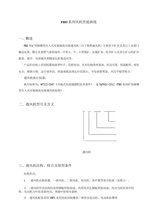
FBD系列风机性能曲线一、概述FBD列矿用隔爆型压入式对旋轴流局部通风机(以下简称通风机)主要用于矿井及其它工业部门输送瓦斯、煤尘及易燃气体的场所,可供大、中、小型煤矿、金属矿业、化学矿山及其它矿山的矿井掘进、建井、局部通风和隧道长距离送风等。
产品在结构上采用机翼扭曲型叶片、直联传动,具有结构简单紧凑、传动可靠、坚固耐用、使用安全、维修方便,运行效率高,性能曲线高效运行范围大、节电效果明显、风压平稳等特点。
通风机执行标准:执行标准为:MT222-2007《对旋式局部通钢机技术条件》、Q/YAF001-2012《FBD系列矿用隔爆型压入式对旋轴流局部通风机标准》。
二、通风机型号及含义通风机三、通风机结构、特点及使用条件结构形式:1.通风机由集流器、一级风机、二级风机、电动机、消声器等部分组成(见图1)。
2.通风机外壳结构均采用钢板焊接而成,内筒用多孔钢板焊接而成,内衬为优质消声材料,电动机与叶轮直联传动,两级叶轮相对旋转。
3.通风机配套采用YBF2系列风机用隔爆型三相异步电动机,电动机防爆型式为:隔爆型,防爆标志:Exdb1图1:FBD系列风机结构示意图FBD系列风机外型尺寸表主要特点:1.高效率:FBD系列风机设计精良,工艺先进。
其叶片采用三元流体设计,呈机翼扭曲型,风机高效工况区面积大,使运行的风机总是处于高效的工作范围内。
2.低噪音:FBD系列风机采用对旋直联传动,与旧风机相比,减少了导叶装置,在增加风机压力的同时,又理顺了空气流动的方向,降低了空气的摩擦声;机壳采用外包复式消音装置,整机运行噪声可控制在85分贝以下(比A声级在35分贝以下),具有超低噪音特性,对改变井下约束空间的噪声环境效果显著。
3.风压较平缓,喘振现象微小。
在风压高、小流量区域同样运行稳定。
在井下送风距离远,对复杂巷道适应性强。
使用条件:a)温度不超过・20℃~+40℃;b)湿度不大于95%(+25C时);c)大气压力为86kPa~106kPa;d)无腐蚀性气体;e)在具有甲烷混合物及煤尘爆炸性危险的煤矿井下,安装在进风巷道中,与正压风筒配套使用,作压入式通风;f)工作电压为380v∕660v;660v∕1140v两种,且不超过额定值的±5%,电压频率为50HZo四、通风机主要性能参数(见附表一)五、通风机安装、运行、维护通风机的安装:1.安装前,检查叶片顶部与机壳内筒间的径向间隙是否均匀,单侧最小间隙应大于1mm;2.检查电机定子绕组的冷态绝缘电阻,必须大于50兆欧;3.检查配套电器设备,电压、容量是否满足要求,各项保护是否良好;4.检查风机各连接部分有无松动,筒体是否在运输过程中损坏变形;5.电机应按标识正确接线,接线要牢固,并做好各部分的绝缘。
上虞专用风机有限公司D、F 式系列离心风机使用说明书目一.产品简介1.结构特点 2.使用范围 3.附图录二.使用说明1.用户收货检验的程序 2.安装前的贮存和保管 3.风机安装前的重要技术准备 4.安装风机及调整程序 5.使用运转的程序 6.制造厂重要提要:绝对禁止的错误操作项目 7.风机使用中的故障及排除2上虞专用风机有限公司D、F 式系列离心风机使用说明书一.产品简介D、F 型(联轴器传动型)离心通风机可作为各行各业的通风、引风、换气用, 同时也适用于大型锅炉送引风, 钢铁厂冶炼除尘设备。
如输送气体有其它具体变化时, 可制作成特殊材料风机。
1.结构特点(参见附图一,以 D 型结构为例) 此型风机的组成部分主要由:叶轮组、机壳、进风口、联轴器、进气箱(F 式)等部 件配电机而组成。
1.1 叶轮由前盘、后盘及叶片组成。
由轮毂联接上主轴,通过联轴器与电机传动。
因用户使用条件的不同而选用不同的材质;通常用钢板、铸铝合金或高强度的低合金 钢。
使用于含腐蚀性介质的场合则应选用特殊不锈钢。
1.2 机壳为整体式或可剖分拆开,机壳用钢板制作成蜗形体,根据用户的需要, 可设有排水口,清灰门,大型的机号可设置人孔门。
1.3 集流器(俗称进风口) ,一般为整体式,轴向剖面为曲线形状(呈喇叭口型) , 能使介质以最低的阻损流线通过。
1.4 联轴器起到把电机的扭矩传给主轴的叶轮。
1.5 进气箱(F 式)为矩型,整体呈收敛型,用底部支撑架固定在基础上,外壁面 有网状筋板以增强刚性。
3上虞专用风机有限公司D、F 式系列离心风机使用说明书附图一(D 型结构)2.风机的重要结构要素 2.1 旋向:顺、逆旋向的判断。
从电动机一侧正视,叶轮顺时针旋转的,称为右 旋,以“右”表示;叶轮逆时针旋转的,称为左旋,以“左”表示。
2.2 出口角:以机壳的出风口角度表示。
按风机行业的标准,一般由 0°、45°、 90°、135°、180°、225°、275°、315°,如用户对设备安装角度有特殊要求,订 货时需注明。

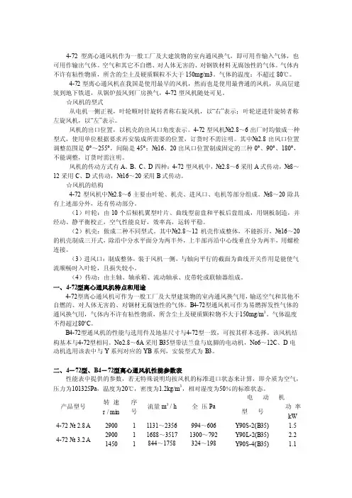
4-72系列离心通风机使用说明书 北京大福桥机电有限公司用 途4—72型离心通风机主要用途是为—般工厂及大型建筑物的室内通风换气或输送空气及其它不自燃、不易爆、不挥发、对人体无害、对钢材无腐蚀性之气体:B4—72型离心通风机可排送易燃、易挥发性气体;F4—72型离心通风机主要用于输送腐蚀性气体。
但4—72、B4—72、F4—72离心通风机输送的气体均不得含粘性物质,所含尘土及硬质颗粒物不大于150mg/m3,气体温度不得超80℃。
B4—72型风机的性能与选用件及地基尺寸与4-72型一致,可按其样本选择。
该风机结构基本与4-72型相同,Nn2.8A—6A采用B35型带法兰盘与底脚的电动机,No6~12C、D电动机选用表中与Y 系列相对应的YB系列,安装型式为B3。
F4—72型离心通风机采用不锈钢、玻璃钢或其他耐腐蚀材料制造,其性能和地基尺寸与4—72型离心通风机相同。
4—72型离心通风机在我国是使用最早的风机,然而也是使用最普遍的风机,从高层建筑到地下铁道,从锅炉鼓风到厂房换气,从北部边疆到南海之滨,从西部高原到东部边垂,4—72型风机随处可见。
型 式从电机—端正视,凡叶轮按顺时针方向旋转者均称“右旋风机”,以“右”表示,反之则均称之为“左旋风机”以“左”表示。
风机的出风口位置以机壳的出风口角度表示,4—72型风机N_o2.8~6在出厂时均做成—种型式,使用单位根据要求再安装成所需要的位置,订货时无须注明。
其中:No2.8出风口位置调整范围是0°~225°,间隔是45°;No3.2~6出风口调整范围是0°~225°,间隔是22.5°;No8~12出风口调整范围是0°~225°间隔是45°;No16、20出风口角度制成固定的三种0°、90°、180°,不能调整,订货时需注明。
风机的传动方式有A、B、C、D四种:4—72型风机中,No2.8~5采用A式传动,No6既有A 式传动又有C式传动,N n8~12采用C、D式两种传动方式,N o16~20采用B式传动。
4-72型离心通风机作为一般工厂及大建筑物的室内通风换气,即可用作输入气体,也可用作输出气体。
空气和其它不自燃、对人体无害的、对钢铁材料无腐蚀性的气体。
气体内不许有粘性物质,所含的尘土及硬质颗粒不大于150mg/m3。
气体的温度:不超过80℃。
4-72型离心通风机在我国是使用最早的风机,然而也是使用最普通的风机,从高层建筑到地下铁道,从锅炉鼓风到厂房换气,4-72型风机随处可见。
☆风机的型式从电机一侧正视,叶轮顺时针旋转者称右旋风机,以“右”表示;叶轮逆进针旋转者称左旋风机,以“左”表示。
风机的出口位置,以机壳的出风口角度表示。
4-72型风机№2.8~6出厂时均做成一种型式,使用单位根据要求再安装成所需要的位置,订货时不需注明。
其中№2.8出风口位置调整范围是0°~255°,间隔是45°;№16、20出风口位置制成固定的三种0°、90°、180°,不能调整,订货时需注明。
风机的传动方式有A、B、C、D四种:4-72型风机中,№2.8~6采用A式传动,№8~12采用C、D式传动,№16~20采用B式传动。
☆风机的结构4-72型风机中№2.8~6主要由叶轮、机壳、进风口、电机等部分组成。
№8~20除具有上述部分外,还有传动部分。
(1)叶轮:由10个后倾机翼型叶片、曲线型前盘和平板后盘组成,用钢板制造,并经动、静平衡校正,空气性能良好,效率高,运转平稳。
(2)机壳:做成二种不同型式。
其中№2.8~12机壳作成整体,不能拆开,№16~20的机壳制成三开式,除沿中分水平面分为两半外,上半部再沿中心线垂直分为两半,用螺栓连接。
(3)进风口:制成整体,装于风机一侧,与轴向平行的截面为曲线开关作用是能使气流顺畅时入叶轮,且损失较小。
(4)传动:由主轴、轴承箱、流动轴承、皮带轮或联轴器组成。
一、4-72型离心通风机特点和用途4-72型离心通风机可作为一般工厂及大型建筑物的室内通风换气用,输送空气和其他不自燃的、对人体无害的、对钢材无腐蚀性的气体。
YBT系列矿用隔爆型轴流式局部通风机使用说明书XXXXXXXX电器有限公司目录1 适用范围与用途 (1)2 型号含义 (1)3 技术参数 (1)4 结构概述 (2)5 安装及注意事项 (2)6 维护与修理 (3)7 包装、运输与贮存 (4)8 订货须知 (4)安装使用前请仔细阅读使用说明书1 适用范围与用途YBT系列矿用隔爆型轴流式局部通风机(以下简称通风机),适用于含有爆炸性气体混合物(甲烷)的煤矿井下,在交流50Hz,电压为380V或660V的线路中,作为局部通风用,也可作为隧道和大建筑物的通风换气之用。
通风机在下列条件下,应能可靠运行:a.海拔不超过1000m;b.环境空气温度为-20℃-+50℃;c.环境空气相对湿度不大于95%(25℃时);d.空气中含有爆炸性(甲烷)气体混合物的煤矿井下;e.在无显著摇动和冲击振动的地方;f.无腐蚀金属和破坏绝缘的气体或蒸气的环境中。
2 型号含义Y B T №□ / □Ⅱ叶轮数风机额定功率 kW机号用叶轮分米数来表示通风机隔爆型Y系列电机3 技术参数3.1 产品执行标准GB3836-2010 爆炸性环境MT 222-2007 煤矿用局部通风机技术条件3.1 防爆型式:矿用隔爆型防爆标志:ExdI;3.2 技术参数见表1表1 主要技术参数4 结构概述4.1 该系列通风机其结构形式为矿用隔爆型轴流式,该通风机由吸流器、叶轮、电动机、防爆接线盒、机体、导流器等六部分组成。
机体及结构采用钢板焊接而成:采用电动机与叶轮直联方式,传动可靠;整机结构简单紧凑,坚固耐用,使用安全,维修方便。
4.2 电动机为YBF 系列矿用隔爆型二极三相异步电动机,电压等级为380/660V ,电动机的机座与机体焊成一体,电动机叶轮输送的气流直接进行冷却。
4.3 通风机法兰上焊有接地螺栓,供现场直接接地使用。
4.4 在出风筒的凸缘法兰上,钻有均匀分布的小孔,用于连接变径短节或直接胶质风筒。
FBCDZ系列煤矿地面用防爆抽出式对旋轴流通风机使用说明书(机号大于等于№17)代号:0AP.466.015i执行标准:GB/T21151-2007Q/NF177-2012南阳防爆集团股份有限公司2012年09月目录首先感谢您选用CNE牌FBCDZ系列煤矿地面用防爆抽出式对旋轴流通风机,在您使用通风机之前,请您先仔细阅读这本《使用说明书》,它会告诉您如何正确操作、维护,使其更好地为您服务,并请您妥善保管好这本《使用说明书》,以便今后使用。
1.概述 (1)2.FBCDZ通风机型号代表的意义 (1)3.通风机技术参数、工作条件 (1)4. 结构简介 (2)5.贮存及保养 (3)6.安装 (3)7.试运转 (7)8.使用维护 (8)9. 注意事项 (11)10.通风机常见故障及排除 (11)11. 随机资料 (11)FBCDZ系列煤矿地面用防爆抽出式对旋轴流通风机, 执行标准为GB/T21151《煤矿用轴流主通风机技术条件》和Q/NF177《FBCDZ系列煤矿地面用防爆抽出式对旋轴流通风机技术条件》。
其防爆性能符合GB3836.1-2010 《爆炸性环境第1部分:设备通用要求》和GB3836.2-2010 《爆炸性环境第2部分:由隔爆外壳“d”保护的设备》的规定。
1 概述FBCDZ系列煤矿地面用防爆抽出式对旋轴流通风机(以下简称通风机)是我公司研制的新一代通风机产品。
通风机气动性能优异、效率高、振动小、噪声低、反风量大、高效区域宽广,并采取了确保通风机安全、可靠运行的多种措施,研制的专用防爆电机,具有效率高、温升低、振动小、噪声低、轴承温度低、过载能力强等特点,从根本上解决了在用风机的缺陷,确保长期运行。
通风机适用于大中煤矿矿井作地面抽出式通风机。
通风机产品执行标准为GB/T21151《煤矿用轴流主通风机技术条件》和Q/NF177《FBCDZ系列煤矿地面用防爆抽出式对旋轴流通风机技术条件》。
2 FBCDZ通风机型号代表的意义:F B C D Z №□/ 2 ×□装机功率,kW配用电动机台数机号,以叶轮直径的分米数表示主要对旋抽出式防爆通风机3 通风机技术参数、工作条件3.1 技术参数3.1.1 通风机的定额为:连续工作制S1。
通风机产品使用说明书OPERATING MANUALFANS目录一、用途 (3)二、结构型式 (3)三、主要零部件及装配关系 (5)四、风机的安装调试和操作 (5)五、风机的维护和保养 (8)六、风机运转中主要故障及消除 (10)TABLE OF CONTENTSI APPLICATION (11)II CONSTRUCTION (11)III MAJOR PARTS AND ASSEMBLY (13)IV INSTALLATION AND OPERATION (14)V MAINTENANCE (19)VI MAJOR FAIL URES IN OPERATION AND SOLUTIONS20一、用途通风机广泛应用于工厂、矿山、电站(厂)、石油、化工、冶金、轻纺、建材等各个行业的通风换气、排烟除尘、物料输送、锅炉送、引风等。
输送的介质主要为空气、烟气等,介质中所含的尘土或硬质颗粒不大于150mg/ m³。
所输送介质的温度,送风机一般要求不超过80℃,引风机一般要求不超过250℃。
通常在引风机入口加装除尘效率较高的除尘装置,减少进入风机介质的含尘量,延长风机的使用寿命。
二、结构型式通风机的结构形式一般分为两大类:一类为离心式,另一类为轴流式。
离心式为轴向进风,径向出风。
轴流式为轴向进风,轴向出风。
从电动机一侧正视,叶轮顺时针旋转称为右旋风机,以“右”或者以“顺”表示。
叶轮逆时针旋转称为左旋风机,以“左”或者以“逆”表示。
风机的传动方式有A、B、C、D、E、F六种,根据使用现场和机号大小而选用。
离心式风机(1)离心风机不但有“左”“右”之分,还有机壳的出口角度之分,一般机壳出风口有0°、45°、90°、135°、180°、225°、270°七种角度。
(2)叶轮:叶轮是通风机的关键部件,它是由一定数量的叶片、前盘、后盘、轴盘组成、叶片有机翼型、单板型。
前盘可制成弧形或锥形,后盘为平板型。
(3)机壳:机壳是由蜗板、侧板、支腿、进口法兰、出口法兰等组成。
为了运输方便,机壳可以制成二开箱或三开箱式,通过对口法兰螺栓联接到一起。
(4)进风口:进风口制成收敛流线型的整体结构,通过法兰联接,安装在风机入口侧与叶轮同轴,使气体轴向顺利进入叶轮,流动损失小。
(5)传动组:风机的传动组由主轴、轴承箱、轴承及轴承装配组件、油位指示器、温度计等组成。
引风机的传动组备有冷水系统,现场须加装输水管。
(6)调节门:调节门是用来调节风机流量的装置,D式风机调节门为花瓣式,调节门轴向安装在进风口前面,调节范围由90°(全闭)到0°(全开)。
通过壳体外部转动的搬把进行调节,其搬把的位置从进风口方向看在右侧,对于右旋风机,搬把从下往上推是由全闭到全开方向,对于右旋风机,搬把由上往下拉是由全闭到全开方向。
F式风机调节门的调节叶片为机翼型,采用联动柄进行调节。
为使调节门各部正常工作,必须很好地润滑,对通风机的调节门可采用钙钠基润滑脂润滑。
对引风机,因气体温度较高,润滑脂可采用二硫化钼高温(260°)润滑脂。
(7)传动组轴承润滑,送风机一般采用脂润滑,引风机一般采用油润滑,一般为30#机械油。
三、主要零部件及装配关系离心风机的组成:叶轮、机壳、进风口、(调节门)、传动组、(皮带轮)、防护罩、地脚螺栓、测温仪表、油位指示器等。
轴流风机的组成:叶轮、机壳、集风器、整流罩(整流体)、支架、传动组(直联风机无传动组)、联轴器(皮带轮)。
四、风机的安装调试和操作在安装风机前,首先应准备好安装使用材料及工具,并对风机各部分的机件进行全面检查。
叶轮雨机壳旋转方向是否一致,内部联接是否紧密,有无松动。
主轴和轴承等主要部件有无损伤,传动部是否灵活,如发现问题应及时检修调整好。
然后用煤油清洗轴承内部。
在安装过程中应该注意以下几点:1.在安装时,一些结合面上为防止生锈,减少拆卸困难,应涂上润滑脂或机油。
在安装接合面的螺栓时,如有定位销钉,应先上好销钉,再拧紧螺栓。
2.在安装时应注意检查机壳及其他体内,不应有掉入和遗留的工具、杂物。
3.安装要求:(1)风机安装时应先将风机的底座放到基础上,在基础表面和底座表面之间,插上垫铁,通过调整垫铁的厚度,达到安装要求。
垫铁必须成对使用,垫铁表面必须平整,每组垫铁一般不超过3—4块,厚铁放在下层,而最薄的应夹在中间,以免产生翘曲变形,同一组垫铁放置必须整齐,设备调好水平和方位,再将每组垫铁焊接固定好。
在调整水平过程中应结合地脚螺栓同时进行。
(2)风机地脚螺栓采用二次灌浆法安装。
地脚螺栓埋入基础上的预留孔,复校其方位精确度是否准确,然后将机身底座和基础混凝土间隙灌入足够的灰浆,以形成混凝土结构件。
地脚螺栓预留孔的大小,按螺栓直径而定。
对直径为20—30mm的螺栓,预留孔的口子应为100mm×100mm,相应的孔底是110mm×110mm;对直径大于30mm的地脚螺栓预留孔的口子是200mm×200mm,其相应孔底是220nma×220mm。
以上两种预留的孔深由螺栓长度规范决定。
孔的纵切面是梯形即可。
在灌入灰浆时,应特别注意收缩性、龟裂及施工有关规范,待灰浆充分硬化后,才能拧紧地脚螺栓的螺帽。
(3)在大型通风中,机壳与底座是分开的,机壳本身也往往分成几部分,此时应将机体底座、轴承底座按上述方法安装后,按顺序,边调整定子和转子间的间隙边组装。
组装过程中,应注意重要部位是否有毛刺、卷边、变形等。
组装时注意不要弄脏、不要撞击研合面,精心施工。
(4)组装机壳是应以转子轴线为基准找正机壳的位置。
进风口与叶轮进口圈的轴向插入深度和径向间隙,应调整到随机文件规定的范围内。
套口形式的轴向伸进重叠段多半小于或等于叶轮直径的0.008—0.012倍,其径向单面间隙,小于或等于叶轮直径的0.0015—0.0040倍。
机壳后侧板轴孔应与主轴同心,不得互相刮碰。
(5)轴承箱与底座应紧密结合。
整体安装的轴承箱找正、调整时,纵横向水平度用水平仪在轴承箱中分面上测量,纵向水平度也可在主轴上测量,其纵向水平度允差均应不超过0.1/1000。
(6)左右分开式轴承箱找正、调平时,纵向水平度应用水平仪在其中分面上测量,主轴水平度在主轴上测量。
水平度允差应符合下列要求:a每个轴承箱纵向水平度误差不超过0.04/1000;b每个轴承箱横向水平度误差不超过0.08/1000;c主轴水平度误差应不超过0.04/1000;d主轴与轴箱孔轴线在水平方向的同轴度误差不超过 0.06mm;e保证主轴的水平位置,并测量主轴与机电轴同轴度及联轴器两端面的平行度。
两轴的同轴度允差为0.05mm,联轴器两端面的平行度允差为0.05mm。
风机安装后,拨动转子,检查是否有过紧或与固定部分碰撞现象。
安装风机进口和出口管道时,管道重量不应加在机壳上。
安装进风管道时克直接利用进风口本身螺栓联接,此时进风口的固定靠三个沉头螺钉。
全部安装后,经总检查合格后,方可试运转。
4 风机的试运转风机的试车应在无载荷(关闭进气管道砸门或调节阀门)的情况下启动,如运转情况良好然后再逐渐打开调节门,在满载荷的正常工况(规定的全压和流量)情况下运转至规定时间后,经检查无异常现象发生,方可投入正式运行。
在正常工况下连续运转时间;对新安装风机不少于2小时,对修理后安装的风机不少于半小时。
5风机的操作风机操作规程:(1)关闭进风调节门,出风调节门稍开(如有出风调节门);(2)检查风机机组各部分间隙尺寸,转动部分与固定部分不允许有碰撞机摩擦现象,所有固定零件的螺栓应拧紧;(3)检查轴承箱的油位是否在最高与最低油位之间;(4)对联轴器或用皮带转动的风机,要检查联轴器或带轮、皮带安装的是否可靠。
风机轴与电机轴的同轴度是否符合技术规定。
(5)引风机备有冷水装置,因此必须加装输水管,耗水量随气温不同而异,一般按0.5—1m³/h考虑,水压不超过0.2MPa.检查电气线路及仪表安装是否准确完好。
(6)在风机启动过程中,应严格检查机组的运转情况,如发现风机严重振动或有撞击声,轴承温度剧烈上升,应立即停机,检查其原因,并进行消除。
当风机启动达到正常转数后,逐渐开大调节门,直至规定负荷为止。
在运转过程中,轴承温升不得高于周围环境温度40℃。
轴承盖表面温度不高于80℃,轴承的均方根振动速度值不大于6.3mm/s。
五、风机的维护与保养1、风机安装使用后,每台风机应建立保养账目,以此为基础进行定期检查,维修。
无论哪种风机至少每一年进行一次定期检修。
2、风机连续运转3个月,进行一次滚动轴承的检查,检查滚柱和滚道表面的接触情况及内圈配合的松紧度,更换一次润滑脂(或油)其润滑脂以装满轴承空间的三分之二为宜;润滑油按油位指示器显示。
3、风机定期维护保养,消除风机内部的灰尘、污垢等。
4、检查各种仪表的准确度与灵敏度。
5、对未使用的备用风机,或停机时间过长的风机,应定期将转子旋转120°—180°以免主轴弯曲。
六、风机运转中主要故障及消除I APPLICATIONFans are widely used in kinds of industries like manufactory, mine, power station, petroleum, chemical industry, metallurgy, textile factory and building material with the functions of ventilation, discharging flue, aspirating,material handling, blowing-in or induced air to boiler. The transported gas is or fume and dust and granule in the gas should not exceed 150mg / m³. The gas temperature of forced draught blower is≤80 ℃and the one of induced fan is ≤250 ℃. There would be usually .installing a high efficiency dust cleaning apparatus in the entrance of induced fan to reduce the dust load of gas and extend the fan operating life.II CONSTRUCTIONThe kind of fan is centrifugal or axial.The air-inlet direction of centrifugal fan is axial,and the air-outlet one is radial. The air-inlet direction of axial fan is axial,and the air-outlet one is also axial .Viewing from the side of the motor, the impeller rotating in the clockwise is called the anti-clockwise fan re-marked with left. The kind of drive is according to the service site and size of fan.It includes A, B, C, D, E, and F.CENTRIFUGAL FAN(1)The centrifugal fan can be divided into clockwise one and anticlockwise one, it also has differences in the angle of the outlet includes 0 °, 45 °, 90 °, 135 °, 180 °, 225 °,and 270 °.(2)Impeller: The impeller is the key component of fan, It consists of blades, shroud cover, main disc and boss. The blade is divided into airfoil one and plate one the shroud cover is divided intoarc and cone, and the main disc is flat plate.(3)Casing: The casing consists of scroll, side wall, supports, inlet flange, outlet flange and so on. In order to be transported conveniently, the casing can be made into bi-box or three-box connected with flanges and bolts.(4)Inlet section: The inlet section installed in the inlet side of fan is streamline and parallel with the axial, which makes gas flow into impeller smoothly with axial direction and less flow loss, and it is connected with flange.(5)Transfer unit: The transfer unit of fan consists of main shaft, bearing housing, bearings, bearing subassembly, oil level indicator, thermometer and so on. A cooling water system is equipped in the transfer unit of induced fan, and there should be hydraulic pipeline in the service site.(6)Adjust door: The adjust door is used for adjusting wind current.Kind of D adjustor door is petal-like which is installed axially in front of the inlet section, the adjustable range is from 90 ° (full cut-off) to 0 ° (full open) adjusted by the reversible wrench outside the casing. Viewing from the side of the inlet section, the wrench is in the right. When boosting up wrench, theadjustor door is from full cut-off to full open for clockwise fan and is from full open to full cut-off for anticlockwise fan .Kind of F adjustor door is airfoil adjusted by linked haft. The adjustor door should be lubricated commendably to make sure the parts are in normal work .The adjustor door of Ventilating fan is lubricated with Ca-Na grease, and the one of induced fan is lubricated with molybdenum disulphide high-temperature grease (260 °).(7)The forced draught blower uses grease to lubricate the bearing of transfer unit, and the induced fan uses oil which usually is machine oil 30 #.III MAJOR PARTS AND ASSEMBLY Composition of centrifugal fan: impeller, casing, inlet section, (adjustor door), transfer unit, coupling (belt pulley), protective covering, base bolt, thermometer, oil level indicator and so on.Composition of axial fan: the impeller, casing, bell mouth, fairing (rectifier), steadier, transfer unit (none in direct-drive fan), coupling (belt pulley).IV INSTALLATION AND OPERATION There must be preparing materials and tolls used in installation in the first and checking each part of fan before the installation. The rotating direction of the impeller is in conformity with the one of the casing. Each connection part should be tight, free from being loosened or missed .The key parts like main shaft and bearing are having no damage .The transfer unit is rotating smoothly .It should be stopped to repair and adjust in time if there is any fault, then cleaning the inner of the bearing with coal oil.The following points should be noticed in the installation:1 It should be lubricated with grease or machine oil in some bonding surfaces for avoiding rustiness and disassembling instantly. The pin should be fitted over first and then screwing up the if there is a pin bolt when installing the bolt of the bonding surface.2 It should be noticed that there is no tools and objects dropping or leaving in casing and other shells.3 Installation specification:(1) The mounting base should be placed in the ground first. There are sizing blocks between the base face and the ground face. The installation level can be achieved by changing the thickness of the block. The sizing block of which surface is smooth should be mated, and each unit is less than 3 or 4. To avoid distortion, the thick block should be placed in the lower course, and the thinnest block placed in the middle. A set of blocksshould be placed levelly. All parts of fan should set the right level and azimuth, and then welding the unit of blocks, the base bolt should be adjusted at the same time.(2) The base bolt of fan is installed by means of quadric grouting method. The base bolt should be embedded into the prepared hole and be readjusted if the azimuth precision is right. Then injecting enough grout to the gap which is between the base of fan and the ground to form concrete structure. The aperture of base bolt prepared hole is according to the diameter of bolt. The aperture of prepared hole is 100mm × 100mm, and the aperture of hole bottom is 110mm ×110mm in corre-spond ; when the diameter of bolt is 20-30mm. The aperture of prepared hole is 200mm × 200mm ,and the aperture of hole bottom is 220nma × 220mm in correspond when the diameter of bolt is more then 30 mm. These hole-depths are decided be bolt-length norm. The longitudinal section of hole is trapezoidal. The contractility, fissures and construction norms should be noticed when injecting grout. The nut of base bolt could be screwing up when grout is full hardened.(3)The casing which consists of different parts is separated from base in large-scale fan. The bases of fan and bearing are installed according to priority by previous means, and the gap between stator and rotor is adjusted at the same time .There should be no rag, hemming and deformation generated in major parts in process. The lapping in faceshould not be dirty and impacted .It should be well-constructed.(4)The casing is centering is centering by rotor axial line. The axial depth of penetration and radial clearance between inlet section and impeller mouth ring should be adjusted to the range defined by product flies. The linking axial overlay segment of penetration is mostly less than equal to 0.008-0.012 multiple of the diameter of impeller, and the radial gap of one is less then or equal to 0.0015-0.0040 multiple of the diameter of impeller (seeing picture 2). The axle hole in casing rear side wall should be concentric to main shaft, and it should be no between them.(5)The bearing housing should be tightly associative to base plate. Both of longitudinal and cross levelness are measured in mid-separate suiface of bearing housing by level meter when centering and adjusting bearing housing which is in integral erection . The cross levelness could be also measuied in main shaft, and its franchise is less than 0.1 / 1000.(6)Both of longitudinal are cross levelness are measured in mid-separate surface of bearing housing by level meter when centering and adjusting right-left divided bearing housing ,and the main shaft levelness is measured in main shaft. The franchise of levelness should be match to the following requests:a) The cross levelness error of each bearing housing is less than 0.04 / 1000;b) The longitudinal levelness error is less than 0.08 / 1000;c) The main shaft levelness error is less than 0.04 / 1000;d) The axiality error in horizontal direction of hole line of main shaft and bearing housing is less than 0.06mm;e) The main shaft should be level, and then measuring non-axiality between main shaft and motor shaft and non-parallelism of head faces in coupling. The non-axiality between two shafts is less than 0.05mm. The non-parallelism of head of head faces in coupling is less than 0.05mm.After the installation, there is an examination to make that is not too tight and crash between fixed parte when putting rotor. Then weight of the inlet-out pipes should not be added to the fan. The inlet could be connected to bolt of inlet section. The inlet section is fixed by three sunk screws. The could be test-running after examination.4Test-RunningThe test-running of fan is starting up in case of non-load (closing inlet pipe valve or adjustor door). The adjustor door could open wide gradually if the fan is in good working order. Until to the full-load condition (in the specified current and pressure), the fan can be putted into production after running preset-time, and at the same time there is no unconventionality. The continuous running time in normal work condition is less than 2 hours for fan assembled recently, and is less than a half of hour for fan repaired.5 OperationOperation roles of fan:(1) Closing inlet adjustor door, opening outlet adjustor door a little (if having outlet adjustor).(2) Examining the gap dimension of each part. There should be no crash and friction between rotating art and fixed part, and all bolts of fixed part should be screwed up.(3)The oil level of bearing housing should be below the highest level and over the lowest level .(4) For the fan drived by coupling or belt, the coupling or belt wheel and bell pulley should be installed right, and non-axiality of fan shaft and motor shaft should be match to technical specification.(5)The induced fan has cooling water device, same water pipes should be provided to it. Water consumption is different to temperature, it is 0.5to 1.0 stere in general. Water pressure is less than 0.2MPa. Making sure electrical circuit and device are installed right.(6)Examining work condition of each part the starting up. The fan should be stopped if there is any fault such as vibrating in a violent way, giving out abnormal noise and high temperature in bearing, and then examining the fan and solving the problem. When fan is running to regular number of speed, the adjustor door open wide gradually, until to specific load. The temperature rise of bearing is less than 40 ℃toambient temperature, surface temperature of bearing cap is less than 80 ℃, and root-mean-square librating velocity of bearing is less than 6.3mm / s in running.V MAINTENANCE1 After installation, a maintenance and operation card is necessary to each fan. The fan should be examined and repaired periodically. Each must be repaired. at lest once a year.2 After running3 months, there should be an examination for rolling bearing to make sure contact condition in the surface between roller and rollaway and tightness of inner circle is well. Grease or oil should be changed, the quantity of grease is proper when space of bearing is full to 2/3, and the one ofoil is decided by oil level indicator.3 The fan should be subjected to general service to clear the sediments in the casing or the impeller.4 The accuracy and sensitivity of each must be examined.5 The rotor should be rotated 120 °to 180 °to avoid main shaftbending for off-duty fan which is not used or fan of which stop time is too long.VI MAJOR FAIL URES IN OPERATION AND SOLUTIONS21。