推栓门使用手册
- 格式:ppt
- 大小:350.00 KB
- 文档页数:5

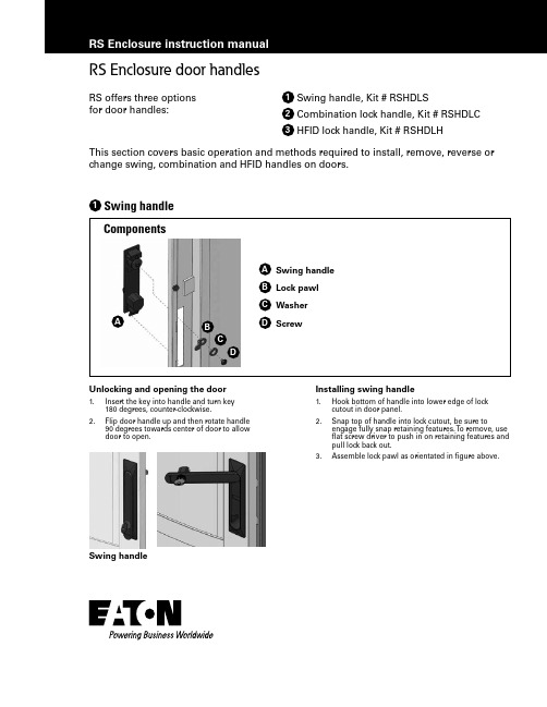
Unlocking and opening the door1. Insert the key into handle and turn key 180 degrees, counter-clockwise.2.Flip door handle up and then rotate handle 90 degrees towards center of door to allowdoor to open.Swing handleInstalling swing handle1. Hook bottom of handle into lower edge of lock cutout in door panel.2.Snap top of handle into lock cutout, be sure toengage fully snap retaining features. T o remove, use flat screw driver to push in on retaining features and pull lock back out.3.Assemble lock pawl as orientated in figure above.RS Enclosure door handlesRS offers three options1 Swing handle, Kit # RSHDLS for door handles:2 Combination lock handle, Kit # RSHDLC3 HFID lock handle, Kit # RSHDLHThis section covers basic operation and methods required to install, remove, reverse or change swing, combination and HFID handles on doors.AB C D1Swing handleUnlocking and opening the doorTo unlock a combination lock swing handle: 1. Set three numbered thumb wheels to zero. 2. Flip door handle up.3.Rotate handle 90 degrees towards center of door toallow door to open.Combination lock swing handleInstalling combination lock swing handleThe following shows how to install or remove a combination swing handle. 1. Disassemble swing handle and align lock with lock cutout in door panel.2. Assemble handle by securing upper spacer and lower cover as shown using supplied screws.3.Assemble lock pawl as orientated in figure.T o change original lock setting1. Make sure combination wheels are at original set position “0-0-0.”2. Use a sharply pointed object(ie: screw driver, pen, etc.) and insert tip into small round hole located on bottom of lock cylinder, push up and hold. 3. Turn three wheels to your desired new combination position and release tip.T o reset1. Turn combination to current set position.2.Repeat steps 2 and 3 above to set new code.Note:To ensure a save and complete locking of number lock, all three number wheels have to be adjusted. Always write down and remember new number.RS DooR hanDlESABCD E F G2Combination lock handleRS DooR hanDlESUnlocking and opening the doorUse optional battery pack kit # RSHFIDBATT(sold separately) to provide temporary external power source to activate locking mechanism.Note : Refer to Dirak Quick Installation Guide (included) for further details on how to access and configure E-LineHFID locking system.HFID lock swing handleInstalling HFID swing handleThe following shows how to install or remove a HFID swing handle. 1. Disassemble HFID handle and align lock with lock cutout in door panel.2. Assemble handle by securing upper spacer and lower cover as shown using supplied screws.3.Assemble lock pawl as orientated in figure 1, E above.Note: T orque requirements for screws: • Upper Screws = .73 – 1.10 ft-lb [1-1,2 N-m]• Lower Screws = .29 ft-lb [0,4 N-m]4.Route control cable from HFID handle down and across bottom of door and enter to enclosure via hinge side, use plastic wire clips (H) to secure. See Figure 2 above.*6.Use plastic clips and adhesive pad to route cable, as well as secure control box and power supply within enclosure.5.Route wire and connect to control module inside enclosure.AB CD E F G3HFID lock handle Figure 1Figure 2IJHLKBecause enclosure and equipment layout vary, it is best for install professionals to complete final installation once layout and equipment have been finalized. Additional HFID administration software is available, kit # RSHFIDADMSW.* Recommended cable path on doorEaton1000 Eaton Boulevard Cleveland, OH 44122 United States © 2016 EatonAll Rights Reserved Printed in USA Publication No. IL159018EN June 2016Eaton is a registered trademark. All trademarks are propertyof their respective owners.DISCLAIMER OF WARRANTIES AND LIMITATION OF LIABILITYThe information, recommendations, descriptions and safety notations in this document are based on Eaton Corporation’s (“Eaton”) experience and judgment and may not cover all contingencies. If further information is required, an Eaton sales office should be consulted. Sale of the product shown in this literature is subject to the terms and conditions outlined in appropriate Eaton selling policies or other contractual agreement between Eaton and the purchaser.THERE ARE NO UNDERSTANDINGS, AGREEMENTS, WARRANTIES, EXPRESSED OR IMPLIED, INCLUDING WARRANTIES OF FITNESS FOR A PARTICULAR PURPOSE OR MERCHANTABILITY, OTHER THAN THOSE SPECIFICALL Y SET OUT IN ANY EXISTING CONTRACT BETWEEN THE PARTIES. ANY SUCH CONTRACT STATES THE ENTIRE OBLIGATION OF EATON. THE CONTENTS OF THIS DOCUMENT SHALL NOT BECOME PART OF OR MODIFY ANY CONTRACT BETWEEN THE PARTIES.In no event will Eaton be responsible to the purchaser or user in contract, in tort (including negligence), strict liability or otherwise for any special, indirect, incidental or consequential damage or loss whatsoever, including but not limited to damage or loss of use of equipment, plant or power system, cost of capital, loss of power, additional expenses in the use of existing power facilities, or claims against the purchaser or user by its customers resulting from the use of the information, recommendations and descriptions contained herein. The information contained in this manual is subject to change without notice.Follow us on social media to get thelatest product and support information.。

Alfa Laval8Sanitary Manually RegulatingValveSMO-R ValveOperating Mechanism1.5-inch2-inch2.5-inch3-inch4-inch Pos.Qty.Description Part No.Part No.Part No.Part No.Part No.1Complete operating mechanism, polished....884-28288884-28288884-28288884-28289884-28289 1Complete operating mechanism, industrial...31353-0531-131353-0531-131353-0531-131353-0531-231353-0531-2 11Hand wheel....................................................31353-0528-131353-0528-131353-0528-131353-0528-131353-0528-1 21Lock screw....................................................31353-0529-131353-0529-131353-0529-131353-0529-131353-0529-1 31Cap.................................................................31353-0468-131353-0468-131353-0468-131353-0468-131353-0468-1 41Washer...........................................................31353-0467-131353-0467-131353-0467-131353-0467-131353-0467-1 51Stem holder....................................................31353-0466-131353-0466-131353-0466-131353-0466-131353-0466-1 61Guide..............................................................31353-0459-131353-0459-131353-0459-131353-0460-131353-0460-1 72Set screw.......................................................221581-92221581-92221581-92221581-92221581-92Valve Parts1.5-inch2-inch2.5-inch3-inch4-inch Pos.Qty.Description Part No.Part No.Part No.Part No.Part No. Stem Seal8∆1Lip seal, EPDM (standard)............................31353-0155-131353-0155-131353-0155-131353-0188-131353-0188-1 1Lip seal, NBR.................................................31353-0155-231353-0155-231353-0155-231353-0188-231353-0188-2 1Lip seal, FPM.................................................31353-0155-331353-0155-331353-0155-331353-0188-331353-0188-3 Clamp91Heavy duty clamp.........................................9612-0112-049612-01-12049612-01-12049612-01-12059612-01-1205Valve Body (industrial)181Valve body, 2 ports, GC................................884-25325-031353-0030-731353-0031-731353-0032-731353-0066-7 1Valve body, 2 ports, W..................................31353-0375-131353-0376-131353-0380-131353-0381-131353-0026-1 1Valve body, 3 ports, GC................................884-25796-0884-2579-5884-2594-631353-0040-7884-2687-5 1Valve body, 3 ports, W..................................31353-0375-631353-0376-631353-0380-631353-0381-631353-0026-6Valve Body (polished)181Valve body, lower 2 ports, GC......................31353-10301031353-1030-231353-1030-331353-1030-431353-1030-5 1Valve body, lower 2 ports, W........................31353-1100-131353-1101-131353-1102-131353-1103-131353-1104-1 1Valve body, lower 3 ports, GC......................31353-10331031353-1033-231353-1031-331353-1031-431353-1031-5 1Valve body, lower 3 ports, W........................31353-1100-231353-1101-231353-1102-231353-1103-231353-1104-2 Valve Plug1Plug complete, EPDM (standard).................31353-0520-131353-0521-131353-0522-131353-0523-131353-0524-1 1Plug complete, NBR......................................31353-0520-231353-0521-231353-0522-231353-0523-231353-0524-2 1Plug complete, FPM......................................31353-0520-331353-0521-331353-0522-331353-0523-331353-0524-3 111Regulating plug..............................................31353-0515-131353-0516-131353-0517-131353-0518-131353-0519-1 121Stem...............................................................31353-0340-131353-0377-131353-0378-131353-0341-131353-1007-5 13∆1Packing, EPDM (standard)...........................31353-0320-131353-0321-131353-0322-131353-0324-131353-0325-1 1Packing, NBR................................................31353-0320-231353-0321-231353-0322-231353-0324-231353-0325-2 1Packing, FPM................................................31353-0320-331353-0321-331353-0322-331353-0324-331353-0325-3 1Packing, PTFE...............................................31353-1211-131353-1212-131353-1213-131353-1214-131353-1215-1 14∆1O-ring, EPDM (standard)..............................990034-01990034-01990034-01990034-01990034-01 1O-ring, NBR...................................................223404-21223404-21223404-21223404-21223404-21 1O-ring, FPM...................................................223404-35223404-35223404-35223404-35223404-35 1Seal-ring, PTFE.............................................9612-4330-019612-4330-019612-4330-019612-4330-019612-4330-01 151Screw.............................................................31353-0514-131353-0514-131353-0514-131353-0514-131353-0514-1∆1Service kit for valve, EPDM........................9611-92-00109611-92-00139611-92-00169611-92-00199611-92-0022∆1Service kit for valve, NBR..........................9611-92-00119611-92-00149611-92-00179611-92-00209611-92-0023∆1Service kit for valve, FPM...........................9611-92-00129611-92-00159611-92-00189611-92-00219611-92-0024 Parts marked with ∆are included in the valve service kits.Recommended Spare Parts: Service kitAlternative for Stem Seal 1.5-inch 2-inch 2.5-inch 3-inch 4-inch Pos.Qty.Description Part No.Part No.Part No.Part No.Part No.Stem Seal 81Lip seal kit, EPDM (standard)..........................9611-92-00789611-92-00789611-92-00789611-92-01429611-92-01421Lip seal kit, NBR ...............................................9611-92-00799611-92-00799611-92-00799611-92-01439611-92-01431Lip seal kit, FPM ...............................................9611-92-00809611-92-00809611-92-00809611-92-01449611-92-0144a l 1Lip seal, EPDM (standard)...............................9612-2806-019612-2806-019612-2806-019612-3088-019612-3088-011Lip seal, NBR ....................................................9612-2806-029612-2806-029612-2806-029612-3088-029612-3088-021Lip seal, FPM ....................................................9612-2806-039612-2806-039612-2806-039612-3088-039612-3088-03b 1Plate ..................................................................9612-2805-019612-2805-019612-2805-019612-3087-019612-3087-01c l 1Seal ring, EPDM (standard).............................31353-0128-131353-0128-131353-0128-131353-0205-131353-0205-11Seal ring, NBR ..................................................31353-0128-231353-0128-231353-0128-231353-0205-231353-0205-21Seal ring, FPM ..................................................31353-0128-331353-0128-331353-0128-331353-0205-331353-0205-3FEP Seal 8d 1Washer..............................................................31353-0452-131353-0452-131353-0452-131353-0452-231353-0452-2e l 1O-ring FEP/Silicone ..........................................9611-99-29099611-99-29099611-99-29099611-99-29109611-99-2910f 1Holder................................................................31353-0453-131353-0453-131353-0453-131353-0454-131353-0454-1g l 1Valve body packing ..........................................31353-0451-131353-0451-131353-0451-131353-0451-231353-0451-2l 1Service kit for alternative stem seal, EPDM .....9611-92-04719611-92-04759611-92-04799611-92-04839611-92-0491l 1Service kit for alternative stem seal, NBR .......9611-92-04729611-92-04769611-92-04809611-92-04849611-92-0492l 1Service kit for alternative stem seal, FPM........9611-92-04739611-92-04779611-92-04819611-92-04859611-92-0493l1Service kit for alternative stem seal, FEP ........9611-92-04749611-92-04789611-92-04829611-92-04869611-92-0494Parts marked with l are included in the alternative stem seal service kits.Sanitary Manually RegulatingValveSMO-R ValveAlfa Laval。

资料内容仅供您学习参考,如有不当或者侵权,请联系改正或者删除。
FJK-F(S)-F(D)-LX08一、概述二、主要技术参数1、工作电源: 主电源 AC 380V ±10-15% 50H± 1%Z2、允许外接电机功率<1KW3、门卫反馈触点容量 DC24V/500mA+55℃4工作环境: 温度 -10℃~相对湿度≤95%大气压力 85106Kpa~三、主要功能1、具有两种自动控制方式①烟、温感两部降: ( SW1位于ON位) : 烟感动作后( 或半降信号) , 卷帘下降至中停位置, 等温感动作后( 或全降信号) , 再下降至下限位置。
②烟感延时两部降: ( SE1位于OFF位) : 烟感动作后( 或半降信号) , 卷帘下降至中停位置, 延时后, 下降至下限位置。
OFF ON具有两种手动控制方式①点动方式: ( SW3位于ON位) 此时要使卷帘连续上升或下降需按住相应的手动按钮不放。
②连动方式: ( SW3位于OFF位) 此时要使卷帘上升或下降只需按一下相应的手动按钮即可。
2、门位反馈功能能够向消防中心反馈卷帘上位、中位、下位三种状态。
3、手动优先逃生功能在火警状态下, 按手动按钮盒上任一键, 卷帘会自动返升方便人员逃生。
4、三相电错相自动纠错/缺相自动保护功能当三相电错相时, 控制器能自动识别并调整相序, 使电机的转动方向不变。
当三相电缺相或未接零线时, 控制器能自动保护电机, 同时控制器的正常灯闪亮、蜂鸣器发出断续声。
四、控制器连接示意图按照控制器连接示意图, 将以下几部分线路正确连至控制器内相应的接线端子上。
1、三相交流电源2、三相电机及上/下限位开关3、门卫状态反馈4、烟、温感探测器( 或半降、全降联动信号)5、手动控制按钮盒注意事项1、三相电源输入的火线、零线不要接反。
2、电机电源的火线、零线不要接反。
3、本控制器连接的消防联动信号一般为无源常开信号, 如需接有源联动信号, 则有源信号的”+”端连接控制器的”7”( 半降) 或”9”( 全降) 号端子, ”-”端连接控制器”10”号, 注意”+””-”端不要接反。

138172801_EN_0614Roller shutter drive RolTop /D+ 868 1Operating and installation instructionsPlease keep these operating instructions for later use, to be available throughout the life of the product! The German manual is the original version.All other documents represent the language translations of the original text.All rights in the case of a patent, utility model or ornamental design registration are reserved.2 General for instructionsThe content structure is based on the life cycles of the elec-tric motor drive (hereinafter referred to as "Product"). The manufacturer reserves the right to make changes to the Speci fi cations stated in these Operating Instructions at any time. These may, in individual cases, be different from the respective product version, however the functional information will not undergo signi fi cant changes or become invalid. The current version of the Speci fi cations may be requested from the manufacturer at any time. No claims may be asserted against the manufacturer as a result of the preceding sentence. Deviations from text or picture state-ments are possible and depend on the technical develop-ment, features, and accessories of the products. Deviating information on special versions will be explained by themanufacturer in the sales documentation. Other information shall remain unaffected by these provisions.2.1 Standards and DirectivesDuring the design process, the basic health and safety requirements of the applicable laws, Standards and Direc-tives were complied with. The safety is con fi rmed by the declaration of conformity (see "Declaration of Conformity"). All safety information in these Operating Instructions refer to the laws and regulations currently applicable in Germany. All instructions in the Operating Instructions shall be ob-served without limitation and at any time. Beside the safety instructions contained in these Operating Instructions, the provisions for accident prevention, environmental protection and occupational safety, which are applicable for the op-erating site, must be observed. Provisions and Standards for the safety rating can be found in the EC Declaration of Conformity2.2 Intended useThe product is intended for use in façade engineering todrive electrically powered roller shutters.The determining factor for the drive is the elero drive com-putation program (/de;service;antriebsberechnungsprogramm.htm). Further fi elds of application have to be arranged with the manufacturer, elero GmbH Antriebstechnik (see Address). The operator will be solely responsible for damages result-ing from improper use of the product. The manufacturer cannot be held liable for personal or material damages caused by misuse or procedural errors, and by improper operation and commissioning.The product may be operated only by trained and author-ized personnel under observance of all safety.Table Of Contents 1Operating and installation instructions12 General for instructions 12.1 Standards and Directives 12.2 Intended use 12.3 Foreseeable misuse 22.4 Warranty and liability22.5Customer service of the manufacturer23 Safety 23.1 General safety instructions 23.2 Layout of the safety guidelines 24Product description35 Assembly 35.1 Mechanical fastening 45.2Electrical connection45.3 Connection example,RolTop /D+ 868 230 V/50 Hz 45.4Initial operation55.4.1 Connection for cable assembly 55.4.2 Connection for radio(transmission operation)55.4.3 Changing / Deleting the end positions 55.4.4 Programme or delete further curtainpositions 55.5 Programming the transmitter 55.6Programming (additional) transmitter56 Troubleshooting 67 Maintenance 68 Repair 69 Manufacturer's address 610 Disassembly and disposal611 Notes on the EC declaration of conformity 712Technical data and dimensions73 Safety3.1General safety instructionsThe instructions on safety that must be observed under all circumstances are included in the separately enclosed lea fl et on safety instructions (13 820 0001).3.2 Layout of the safety guidelinesThe safety instructions in this document are identi fi ed by hazard signs and safety symbols and are designed accord-ing to the SAFE principle. They contain information on the nature and source of the danger of possible consequences and to prevent the danger.The following table de fi nes the representation and descrip-tion of hazard levels with possible personal injury, as used in this manual.Fig. 1 Notation of personal injuryThe following table describes the icons used in these op-erating instructions that are used for imaging of the dan-gerous situation in connection with the symbol of the threat level.Fig. 2 Notation-speci fi c hazardThe following table de fi nes the representation used in the operating instructions and description of situations where damage can occur to the product or refers to important facts, conditions, tips and information.2 | EN © elero GmbHStandards and Directives| SafetyOnly if used according to the speci fi cations of these operat-ing and installation instructions for the safe and proper use and safe operation of the product are guaranteed.Only use radio receivers with equipment and units approved by the manufacturer. The operator does not bene fi t from any protection whatsoever against interference from other remote control equipment and terminal equipment (e.g. also from radio equipment which is correctly operated in the same frequency range). Please note that radio systems must not be operated in areas with an increased risk ofinterference (e.g. hospitals, airports,....). The radio control is only permitted for devices and units with which a functional interference in hand-held/wall transmitters or receiversposes no danger for persons, animals or materials or where this risk is covered by other safety appliances.Intended use includes the observance and compliance with all safety instructions with regards to this operating manual and all applicable regulations, and professional associations of applicable laws for environmental protection. Intended use includes the observance of prescribed operating rules in these operating and installation instructions.2.3 Foreseeable misuseA use which deviates from the intended use stated by themanufacturer, elero GmbH Antriebstechnik (see "Address"), is deemed as foreseeable misuse.2.4 Warranty and liabilityPrincipally, the General Terms and Conditions of the man-ufacturer, elero GmbH Antriebstechnik (see "Address"), apply. The terms and conditions are part of the sales documents and handed over to the operator upon deliv-ery. Liability claims for personal or material damages are excluded when they can be attributed to one or more of the following causes:• Opening of the product by the customer • Unintended use of the product• Improper installation, commissioning, or operation of the product • Structural modi fi cations to the product without the written consent of the manufacturer • Operation of the product with improperly installed con-nections, defective safety devices or improperly installed safeguards • Non-observance of the safety provisions and instructions of these Operating Instructions • Non-compliance with the technical data2.5 Customer service of the manufacturerThe product should only be repaired by the manufacturer in case of a failure. The address for sending to customer service, see the chapter "Address".If you have not purchased the product directly from elero, please contact the supplier of the product.Fig. 3 Notation of property damage as well as additionalinformation The following example represents the basic structure of a safety warning:Type and source of dangerExplanation of the type and source of the danger ►Measures to prevent the danger.4 Product descriptionThe RolTop /D + 868 is a radio-controlled electromechanical tubular motor drive. It performs parallel axial movements. ❑Commissioning of the RolTop /D + 868 does not require any elero assembly cable. The elero assembly cableserves only for the deletion of the end positions and/or for restoring the delivery status if necessary. Commissioning of the RolTop /D+ 868 for setting of different functions takes place using the elero assembly cable or an elero radio transmitter. ❑The RolTop /D + 868 needs fi xed stops at the top and bottom. The use of rigid shaft connectors and plugs stop or angle strips or covert attacks is a prerequisite. There is a relief function at both stop points. ❑If an obstacle is recognised, type S will perform a relief by approx. 2 motor turns; type M will perform approx. 1 motor turn (hanging protection with running free). ❑When the same force deactivation has taken place three times in sequence at the top and bottom, the end posi-tions have been set (self-learning). ❑After obstacle recognition in the area of the end positions, they are immediately corrected down by up to 1 motor turn (360°) if, e.g., a window sill has been installed sub-sequently.5 AssemblyPersonal injury from hot surfaces.Drive heats up during operation, the drive housing can be hot. Possible burning of the skin.►Wear personal protective equipment (gloves).Triggered by a possible material errors may occur orimpact shock and injury due to a gearbox break, bud break or a clutch defect.►Suitable materials are to be used for the construction as well as perform a sampling inspection by double load test according to DIN EN 60335-2-97.Risk of injury due to impact or shock caused by not prop-erly mounted or latched motor bearings. Hazards caused by insufficient stability or stability and stored energy (grav-ity).►Selection of engine bearing torque speci fi cations. ►Drive must be backed up with all attached backup devic-es. ►Check for proper latching on engine mounts and correct tightening torques.Danger of injury due to electric current. Electric shock possible.►Electrical work can only be performed by an authorizedelectrician. Danger of injury due to electric current.Hazardous possibly by parts that have become live in the error state.►Electrical connection is described in the operating and installation instructions including cable bushing.Risk of injury due to malfunctions due to improper installa-tion.Driven by winds and possibly destroyed parts of the appli-cation.►For safe operation, the end positions must be set / pro-grammed. ►Training program of the manufacturer for specialist com-panies.Loss of power supply, termination of machine parts and other malfunctions.►For safe operation, no false mount must be made and the end position settings must be carried out during commis-sioning. Damage to the RolTop /D + 868 due to moisture penetra-tion►For devices with protection class IP44, the ends of all cables or connectors must be protected against theingress of moisture. This measure must be implemented immediately after removal of the RolTop /D+ 868 from the original packaging. ►The drive must be installed in a position in which it is not sprinkled.ImportantIn the delivery status (factory setting), the RolTop /D + 868 in commissioning mode.►You have to set the end positions (see chapter 5.6). This is done self-learning (torque-dependent). Best utilisation of the radio signal.►Place the aerial as freely as possible; in case of bad reception, move the aerial. ►Do not kink, shorten or extend the aerial.►Do not undercut the minimum distance of 15 cm between two radio drives.© elero GmbH EN | 3Product description | Assembly►For units with protection class IP 44, the customer con-nection of the cable ends or connector (cable bushing)must also be carried out in accordance with protection class IP 44. Damage to the Venetian blind from incorrect running direc-tion►The assignment of the running direction UP/DOWN with an elero radio transmitter must be reviewed after teach-ing. Adjustment of the end position at the drive.►Any adjustment of the end positions that occurs indicates an electrical connection error. Readjustment of the end positions is not suf fi cient in this case, since the endpositions are adjusted often. In this case, the drive needs to be replaced and the cause removed.ImportantAll applicable standards and provisions must be observedfor the electrical installation.When connecting the drive to a control, the operating instructions of the control must be observed.For electric connection no transmission and retransmission of the access line or connector is required as a rule. Depending on the mounting plate and/or adapter plateused it is necessary in particular with the RolTop /D+ 868 to remove this screwed plate before a cable exchange. Connection only in free of tension status, in addition drive line without tension1 Using a suitable screwdriver, press out the lock of the device connector to the line.2 Disconnect the plug.3 Insert connector until the latch engages.5.3 Connection example,RolTop /D+ 868 230 V/50 HzN PEL1swbr bl gr/ge 4 | EN © elero GmbHMechanical fasteningElectrical connection | Programming the end positions9 Manufacturer'saddress elero GmbHAntriebstechnik Linsenhofer Str. 65 72660 Beuren Deutschland / Germany Phone: +49 7025 13-01 Fax: +49 7025 13-212 *************Please visit our website if you require a contact outsideGermany.10 Disassembly and disposalDispose of the packaging according to current regulations.Dispose the product after previous use in accordance withapplicable regulations. Disposal is partially subject to stat-utory provisions. The goods to be disposed of must only bedelivered to authorised acceptance points.Environmental informationNo unnecessary packaging was used. The packaging canbe easily divided into three material types: Cardboard (box),Styrofoam (padding) and polyethylene (bag, foam materialprotective foil).The device is made up of materials that can be reused if itis disassembled by a specialist operation. Please observethe local provisions on disposal of packaging material andold devices.Always expect additional danger that does not occur inoperation during disassembly.Danger of injury due to electric current.Electric shock possible.►Physically disconnect power supply lines and dischargecharged energy storage. Wait for at least 5 minutes afterdeactivation for the motor to cool down and the capaci-tors to lose their voltage.►Use suitable, tested and stable climbing aids when per-forming disassembly work above body height.►All work at the electrical system must only be performedby the staff described in the chapter "Safety instructionsfor electrical installation".ScrappingDuring the scrapping of the product, the international,national and regional-specifi c laws and regulations are to becomplied with.Please make sure to consider material recyclability, ease ofdismantling, and separability of materials and componentsas well as environmental and health hazards during recy-cling and disposal.Environmental damage at incorrect disposal►Electronic scrap and electronic components are subjectto the hazardous waste rules and must only be disposedof by approved specialist operation.►Groups of materials such as plastics and metals of vari-ous kinds are sorted for recycling and disposal process.Dispose electrical and electronic componentsDisposal and recycling of electric and electronic compo-nents must comply with the applicable national laws andregulations.6 | EN © elero GmbHTeach in transmitter | TroubleshootingStop bidirectional radio teaching mode:Keep the STOP button pushed for at least 6 seconds untilthe status display lights up (depending on transmitter).6 TroubleshootingFig. 8 Troubleshooting for the RolTop /D+ 8687 MaintenanceThe RolTop /D + 868 is maintenance-free.8 RepairPlease contact your dealer if you have any questions.Please always provide the following information:• Item number and name on the type plate• Type of fault• Previous and unusual events• Surrounding circumstances• Own assumptionTechnical data11 Notes on the EC declaration ofconformityelero GmbH hereby declares that the pipe drive RolTop/D+ 868 complies with the basic prerequisites and the otherrelevant provisions of the EC directives. The completedeclaration of conformity can be found in the download areaof our website.12 Technical data and dimensions© elero GmbH EN | 7We reserve the right to make technical changes.elero GmbH Antriebstechnik Linsenhofer Straße 65 D-72660 Beuren *************Phone: +49 7025 13-01 Fax: +49 7025 13-212。

天津津达电动门说明书天津津达电动门是一种以电力为动力的门类产品,以自动化程度高、便于使用和维护的特点而受到广泛关注和应用。
为了确保用户正确安装、使用和维护津达电动门,以下是相关参考内容的说明书。
1. 产品介绍天津津达电动门适用于各类门窗,如大型商场、写字楼、工厂、医院等公共场所。
它采用先进的电力系统和智能控制技术,具备开门、关门、挡住行人等功能,能够自动感知和响应用户的需求。
2. 安全提示(1) 请在使用津达电动门前仔细阅读说明书,并按照说明书指引安装和操作。
(2) 在安装和调试过程中,请务必断开电源,以免发生触电和其他安全事故。
(3) 请确保门体平稳、牢固地安装在门框上,并定期检查螺钉和连接件的紧固情况。
(4) 当津达电动门遇到障碍物时,请勿强行关闭,以避免造成人员伤害和设备损坏。
3. 使用指南(1) 开门功能:通过遥控器或按钮控制,可以实现门体的自动开启。
(2) 关门功能:设备可自动感知人员通过,自主关闭门体。
也可以通过遥控器、按钮或感应器手动关闭。
(3) 安全感知功能:津达电动门配备了红外光电传感器,能够及时识别门口有无人员通过,避免夹伤行人。
(4) 备用电源功能:在停电情况下,可切换至备用电源模式,以保证正常使用。
4. 维护与保养(1) 每半年进行巡检,检查电动门各部件是否正常,包括电机、传动链条、导向轨道等,并进行必要的润滑和调整。
(2) 定期清洁门体表面,避免灰尘和腐蚀物堆积导致性能下降。
(3) 如发现异常噪音、电机过热、阻力增大等情况,请及时联系专业维修人员进行维护。
(4) 使用过程中,请勿私自拆卸或更换零部件,以免影响正常功能和安全性能。
5. 常见问题解决(1) 门体无法打开或关闭:请检查电源是否正常连接,遥控器或按钮是否工作正常,是否有障碍物阻挡门体运行。
(2) 门体打开或关闭过程中出现异常噪音:请检查门体各部件的紧固情况,以及电机和传动链条是否需要润滑。
(3) 电动门不闭合:请检查门体与门框之间是否有间隙或异物阻挡,以及导向轨道是否正常。
External Manual ReleaseUse of the manual release whilst power is turned on, can cause damage to the limits. Please make surepower is fully turned off before any adjustments. Failure to do this may invalidate your warranty.Please note in the event of a power failure when the door is in the closed position you must turn the crankhandle in the ANTI CLOCKWISE direction to open the door.1) Mark the height you require your external override to go through the wall.2) Drill a 22mm hole all the way through the wall.3) Place the plastic tube into the hole from the front with the plate flush against the outside wall and mark the 4 holes for fixing the plate.4) Then go inside and mark the length to cut off the plastic insert.5) Remove from the wall, drill 4 fixings outside and cut plastic tube to size then reinsert in wall.6) Insert universal joint at bottom of shaft into the plastic tube end and mark 2 fixing holes.7) Mark the length you need to cut the shaft to make fit with stem.8) Cut shaft to size and drill a 5mm hole in the shaft so you can reapply clip to attach shaft to stem. 9) Drill 2 fixing holes for the universal joint10) Attach shaft to stem with clip and place universal joint into plastic tube and screw to wall.11) Remove lock and check to makesure the unit turns.。
推闩式外开防火门释放开关工作原理介绍推闩式外开防火门释放开关安装做法跟普通墙壁开关相似,只是专用接线盒必须予埋结实,因为推闩式外开防火门释放开关要承受门扇的撞击和外拉力。
释放开关本体上有一凹槽,相对应的推闩式外开防火门扇上装有一配套的金属锁钩,锁钩平时嵌入推闩式外开防火门释放开关的凹槽并被扣住,推闩式外开防火门释放开关就将推闩式外开防火门扇拉住使门处于常开状态。
推闩式外开防火门释放开关上有一链条拉栓,有的型号是一拔杆,拉或拔可手动释放金属锁钩(应急状况下也可强行拉门扇),推闩式外开防火门门扇依靠闭门器弹力及顺序器作用将门关闭严紧。
推闩式外开防火门释放开关金属锁钩的保持力在10~50kgf范围内可调。
释放开关常以电磁线圈操作,电源可直接取自联动模块Dc24v直流外控电源,工作电流小于.03A,通电时间小于.055,推闩式外开防火门被释放后线圈回路同时被自动切断。
由于推闩式外开防火门一般由感烟探头联动,同时关闭多扇推闩式外开防火门几率小,所以对直流外控电源的冲击不大,当被控推闩式外开防火门多时,外控电源应加大容量。
推闩式外开防火门释放开关是五线制,其中红、蓝两线接电源;黑白两线接反馈线。
另一种推闩式外开防火门释放开关采用温度控制,选用记忆合金做温控元件,当环境温度达到70口时,温控元件动作,闭锁件脱开,推闩式外开防火门在闭门器弹力作用下关闭。
其原理与防火阀类似。
还有一种符合型产品叫温电双控推闩式外开防火门释放开关,顾名能思义。
以上介绍的推闩式外开防火门释放开关在正常状态下是不通电的,只有在联动时瞬间通电,另外一类推闩式外开防火门释放开关正常情况下必须接通消防专用电源,靠电磁铁吸力将推闩式外开防火门吸住,平时消耗电能,火灾报警联动模块通过切除电磁铁电源来释放推闩式外开防火门,也可以手动控制并有反馈信号功能。
常开推闩式外开防火门自动控制原理对于常开的推闩式外开防火门,民用建筑一般是平开门,单扇时装一个推闩式外开防火门释放开关及一个联动模块,双扇时装两个推闩式外开防火门释放开关及两个单联动模块。
(推栓门使用手册)
有助于我们更好的使用推栓门
消防栓的使用方法
1.打开消防栓
2.取出消防水带,向着火源点延伸展开
3.接上水枪
4.连接水源
5.手握水枪头及水管,打开水阀门,即可灭火
一种固定消防工具。
主要作用是控制可燃物、隔绝助燃物、消除着火源。
消防系统包括,室外消火栓系统,室内消火栓系统,灭火器系统,有的还会有自动喷淋系统,水炮系统,气体灭火系统,火探系统,水雾系统等。
[编辑本段]【消防栓的放置位置】 1、消防栓应该放置于走廊或厅堂等公共的共享空间中,一般会在上述空间的墙体内,不管对其做何种装饰,要求有醒目的标注(写明"消火栓"),并不得在其前方设置障碍物,避免影响消火栓门的开启.
2、消防栓隔在房间(如包厢)内,不符合消防的规定.也不利于消防人员的及时救援. [编辑本段]
【消防栓的使用方法】 1、打开消火栓门,按下内部火警按钮(按钮是报警和启动消防泵的)。
2、一人接好枪头和水带奔向起火点。
3、另一人接好水带和阀门口。
4、逆时针打开阀门水喷出即可。
注:电起火要确定切断电源。
Philips 6000 seriesPush pull smart door lockIntuitive push-pull useSystem wake-up by manual touchManual Locking FunctionDDL161LEFC0Trend leading one-step door openingYour new home derves a new lockPhilips 6100 series push-pull door lock is designed compact and stylish, perfect for youngpeople. With any of the 6 unlocking solutions, you can open the door in one step. Now,forget the keys and embrace an affordable smart new life.Extraordinary design brings outstanding experience•IML brushed finishing: Smooth and wearable as newEasy life doesn't stop there•Patented full auto mortise: Unlock and open at one go•Auto locking: Enjoy the reassurance after closing the door•Intuitive fingerprinting: Unlock swiftly at one goMultiple protection in one for overall home safety•Dual verification unlocking: Security is never forgotten•Fake PIN code: Protect your password security in real time•Outside forced lock: Instant alarm upon inside unlocking•Safe handle: No more safety risks, be reassured while away•C grade lock cylinder: Higher reliability and securityHighlightsAuto locking functionPhilips 6100 series push-pull smart door lock employs full automatic mortise. Without the need for any extra action, the deadbolt will spontaneously pop out after you close the door. If the door is not locked properly, the mortise will give an alarm to remind you of the door lock status.IML brushed finishingThe IML brushed surface has the hardness higher than 2H. Besides, it's waterproof, moisture proof and can keep fingerprint residue out.Intuitive fingerprintingThe fingerprint sensor is integrated in the push-pull handle so that when you hold the handle, your finger will naturally fall on the snesor. You can simply reach out andintuitively touch the sensor, then push to open after a successful fingerprint verification. The one-step unlocking feature will definately bringyou a fast and convenient door opening experience.Patented full auto mortiseThe upgraded full automatic mortise makes it possible for instant unlocking right after a successful verification. Once you arerecognized, you can directly push or pull the handle to open the door, which greatlysimplifies the use of your door lock and brings you a fast and convenient in and out experience.Dual verification unlockingIn dual verification mode, you can use a combination of any two factors (fingerprint, password and card) as the unlocking solution to ensure doubled security for your home.Fake PIN codePhilips 6100 series push-pull smart door lock comes with the feature of Fake PIN Code technology which allows you to enter randomnumber combinations to successfully getidentified as long as there is consecutive input of the real password. This feature caneffectively prevent peeping and safeguard your real password.One-key outside forced lockBefore leaving home, you can touch theoutside forced lock key to enable the function. In this mode, opening the door from inside the room will trigger an alarm. This feature can effectively warn you of security risks and upgrade the level of home security.Safe handle switchYou can enable the safe handle function before you leave home. After the door is locked, the indoor handle will be fixed to ensure that nobody could open the door by pushing the indoor handle. This feature can effectively prevents unlocking from indoor, thuseliminating security risks and improves anti-theft performance.Issue date 2023-11-29 Version: 1.2.1EAN: 69 71318 50059 6© 2023 Koninklijke Philips N.V.All Rights reserved.Specifications are subject to change without notice. Trademarks are the property of Koninklijke Philips N.V. or their respective owners.SpecificationsDesign & Appearance•Color:Red copper•Main Material: Zinc alloy•Surface Processing: Electroplating •Fingerprint Sensor: Semiconductor •Emergency Escape Design: Indoor fast opening mortise•Ergonomic Design: Push-pull handle design Access Solution•Fingerprint•Password/PIN Code•Card/Key Tag•Mechanical KeyLock Capacity•Fingerprint: Up to 100•Card/Key Tag: Up to 100•Master PIN Code: 1•User PIN Code: Up to 10•One-time PIN Code: 1Power Specification•Power Supply: 4 AA batteries•Battery Type: Alkaline Batteries•Time of Use: 8 months*•Maximum Batteries Capacity: 8 batteries •Emergency Power Supply: 5V power bank •Working Voltage: 4.5-6VEasy Operation•Indicator: Door locks status prompt, Low battery prompt, Mute status prompt, Outside forced lock prompt, System locking prompt•Voice Guide: Human voice guide Smart Lock Functions•Mortise: Full auto mortise, Super B-class lockcylinder•Locking Function: Electronic deadlock, Systemlocking•Safety Function: Dual verification, Fake PIN code,Outside forced lock function, Safe handle funtion•Alarm Function: Anti-dismantle alarm, Anti-pryingalarm, Outside forced lock alarmMode•Operationg Mode: Auto mode, Manual mode•System Setup Mode: Dual verification mode,Normal modeInstallation•Door Thickness: 38-60 mm, 60-90 mm, 90-120mm, Other range*•Door Opening Direction: Left inward opening, Leftoutward opening, Right inward opening, Rightoutward oepning•Door Type: Antitheft door, Copper door,Wooden doorAccessory Parts•Accessorial Battery: 4 AA alkaline batteries•Mechanical Key: 2 keys•Smart Key Tag: 2 cards•Installation Accessories•Mortise•Mounting Plate•Drilling Template•Certificate•Cleaning Pad•User Manual•Warranty Card•Quick Start Guide*May be less depending on the actual usage.*Please contact our service agents or authorized dealers for otherdoor range.。