模块十一 热固性塑料注塑模设计
- 格式:ppt
- 大小:1.98 MB
- 文档页数:85
热固性塑料挂口灯头座注射模设计作者:罗文锋来源:《课程教育研究·学法教法研究》2015年第22期【摘要】挂口灯头座注射模采用哈夫模的结构形式,形成产品塑件的外螺纹,其结构简单实用,注射成型工艺过程稳定可靠。
模具采用电热棒加热,以控制热固性塑料成型过程中所需的模温,达到缩短成型周期的目的。
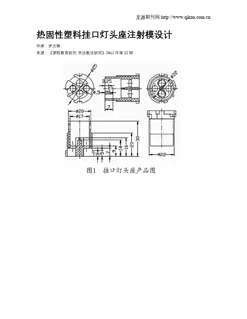
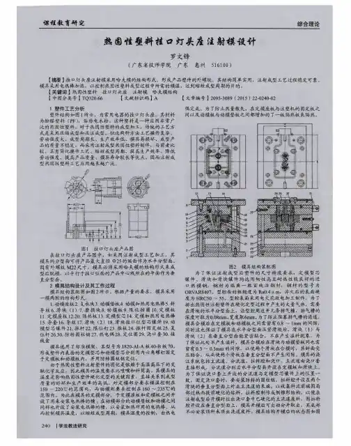
关键词:热固性塑料;挂口灯头座;注射模;哈夫模结构【中图分类号】TQ320.661 塑件工艺分析塑件结构如图1所示,为常用电器的挂口灯头座。
其材料为酚醛塑料(PF),俗称电木粉。
这种塑料是一种应用非常广泛的热固性塑料。
对于热固性塑料的成型加工,传统的工艺方式是采用压缩成型和压注成型。
但这两种方法工艺操作复杂﹑劳动强度大﹑成型周期长﹑生产效率低﹑模具易损坏﹑成型产品的质量不稳定。
而采用注射成型热固性塑料制件,与前者比较,具有简化操作工艺﹑缩短成型周期﹑提高生产效率﹑降低劳动强度﹑提高产品质量﹑模具寿命较长等优点。
因而注射成型热固性塑料工艺应用越来越广泛。
在挂口灯头座产品图中,如采用注射成型工艺加工,其模具的分型面可将产品最大直径Φ25的端面作为水平分型面。
因有外螺纹M22尺寸,模具必须采用哈夫模的结构形式来成型后脱模。
以平行于挂口位面的产品中心线所在的平面作为垂直分型面。
2 模具结构设计及其工作过程模具结构装配图如图2所示。
根据产量的要求,模具采用一模两腔的结构形式。
模具选用了标准模架,其型号为1820-AI-A板40-B板70。
形成塑件内表面的定模型芯和动模型芯分别用内六角螺钉固定于定模板和动模板内,并用防转圆柱销定位。
由于热固性塑料注射塑件的固化是依赖于高温高压下的交联化学反应,因此模具的温度要求比喷嘴和料筒高。
其模具的温度是影响热固性塑件硬化定型的关键因素,直接关系到成型质量的好坏和生产效率的高低。
对定模部分要求模温控制在150~220℃的范围内,而动模则要求控制在160~235℃的范围内。
为此在模具的定模部分,于定模座板和定模板之间开设了用来安装电热棒的槽;在动模部分的动模垫板和动模之间同样也开设了安装电热棒的槽,以安装加热所用的电热棒。
电木粉是由笨酚和甲醛发生聚合反应的酚醛树脂,再加一定的填充料而形成的,是一种热固性塑料.注射电木粉的应用工艺,如能按其性能特点控制,对提高制成品率;减轻注射机的工作负荷;减少对螺杆料筒的磨损;缩短成型周期;改善制件外观会有很大的帮助。
合理使用注射电木粉可使一般氮化钢螺杆的使用寿命延长至8—12个月,并改善对模具的损伤。
一、概念:材料必须在适当的温度条件下经螺杆在料筒内充分熔融塑化,使它呈现良好的熔融状态和流动性,使之具备最佳的注射成型工艺。
注射型电木粉具有良好的料筒热稳定性,120℃条件下料筒内可保持10分钟以上,在85—100℃时呈现最佳熔融流动状态,料筒保持时间可达20分钟。
二、建议料筒温度的设置条件:1.两段控温的料筒:前90—95℃,后75—85℃;2.三段控温的料筒:前90—100℃,中80—90℃,后70—80℃;3.根据配合工艺需要的材料流动性可以用适当提高或降低前料筒温度的办法来调节。
三、背压的关系:注射电木粉为基本颗粒状,除需温度的配合使之熔融外必须调整背压来完成和完善材料的预塑化,使注射过程中流动性良好,加量均匀稳定。
背压的调节一般可控制在加料松退时喷嘴有适当的料流出,和注射过程中调节加料稳定,视不同机器大约在3—5㎏/㎝2四、压力和注射(射料)速度:由于材料充分熔融流动性良好,不需很高的注射压力就能注满型腔,能大幅度降低并减轻机床的负荷,一般在60㎏左右就能满足注射成型的要求。
射料和喷嘴、流道、浇口,模具快速摩擦会产生过高的温度和加剧对螺杆料筒的磨损。
特别是单比例阀控制的注射机,高压高速对螺杆模具等的损伤更为严重,所以射料速度不宜太快。
过慢会影响效率,也不可取。
一般视制件大小和浇口形式,控制在每秒10—25克。
以不产生制件硬泡和气体顶住而注不到头为好。
五、模具温度和保型时间:注射电木粉有较快的成型速度,在170℃条件下就能满足它的成型要求。
保型时间以每毫米14秒并随厚度的增加,时间的增加量递减。

阐述模块式注塑模具设计方案用模块式注塑模具替代原有模具,如应用于职业院校的实训,不仅便于学生的拆装和在教学用注塑机上的安装调试,又利于学生对相关知识的掌握,强化动手能力,提高了学生的学习兴趣,也利于模具的设计;不仅大大降低了安全隐患,而且大大降低实训成本。
一旦应用于实际生产,不仅便于拆装和安装调试,也利于模具的设计和标准化生产;不但会提高效率,而且会降低生产成本。
1 模块式注塑模具的主要结构一种模块式注塑模具的主要结构包括:上模固定板、定模板、动模板、模脚、下模固定板,有由顶针、顶针板、顶针固定板、回针及套在回针上的弹簧所构成的顶针机构,上、下模仁分别固定在上、下通框内(图1)。
2 模块式注塑模具的设计技术方案(1)原有注塑模具主要有单分型面注射模具和双分型面注射模具,以单分型面注塑模具为例,主要结构包括:上模固定板、定模板、动模板、模脚、下模固定板,模脚位于动模板的下侧,在模脚与动模板和动下模固定板所构成的型腔内设有由顶针、顶针板、顶针固定板、回针及套在回针上的弹簧所构成的顶针机构,在定模板与动模板之间分别设有上模仁和下模仁,上模仁固定在定模板的凹槽内,下模仁固定在动模板的凹槽内。
模具的凸模不论是整体式、嵌入式、镶拼式、活动式,凹模不论是组合式的还是整体式的,型芯不论是嵌入式的还是螺纹型芯,都给实训和生产带来一些不便。
整体嵌入式组合凹模及局部镶嵌式凹模,如模腔损坏,虽然可以单独或局部更换型腔,不至于报废整套模具,但产品更新后,整套模具也随之报废。
本模块式模具是一种通用模具,上、下模仁做成模块式(图2),不需要更换模架,只需更换模仁及顶针板或顶针孔板就可以成为一套全新的模具。
(2)在动、定模板上设有下、上通框(图3),上模仁固定在上通框内,下模仁固定在下通框内。
(3)在顶针板上设有顶针孔板通框,顶针孔板固定在顶针孔板通框内。
(4)该模具的运动机构:上、下模仁与该运动机构两者分别结合成一个上、下模块。

塑料注塑产品设计方案模板一、产品概述本项目旨在设计一种塑料注塑产品,以满足市场需求。
本文将提供一个设计方案模板,包括产品的基本要求、材料选择、外观设计等。
二、产品基本要求1. 产品功能:明确产品的主要功能和使用场景,例如是否需要承受一定的载荷、具备特定的耐磨性等。
2. 产品尺寸:根据市场需求和产品功能确定产品的尺寸规格。
3. 产品质量标准:确保产品质量符合相关标准和要求,例如产品的强度、耐用性等。
4. 生产成本:考虑产品的生产工艺和材料成本,以确保产品在市场中具有竞争力。
三、材料选择1. 塑料材料特性:根据产品的功能和要求,选择合适的塑料材料,考虑其强度、耐温性、耐化学品性等特性。
2. 材料供应可靠性:选择供应可靠、品质稳定的材料供应商,以确保产品在不同批次之间具有一致的质量表现。
3. 环境友好性:考虑材料的可回收性和可降解性等环境因素。
四、外观设计1. 产品形状:根据产品功能和市场需求,确定产品的整体形状和结构。
2. 表面处理:考虑产品外观的光泽度、纹理和颜色等方面的处理,以提升产品的质感和美观度。
五、生产工艺1. 注塑工艺:根据产品形状和材料特性,确定合适的注塑工艺参数,包括注塑温度、注塑压力等。
2. 模具设计:设计适用于产品形状和尺寸的模具,保证产品在注塑过程中能够顺利成型。
3. 质量控制:制定完善的生产质量控制方案,包括注塑过程中的质量检测点和品质标准。
六、产品测试与验证1. 产品样品制作:根据设计确定的方案,制作初样或小批量产品,以验证设计的可行性和产品的性能。
2. 产品测试:对产品进行功能性测试、可靠性测试和外观质量测试等,确保产品能够满足设计要求和市场需求。
七、生产计划与成本估算1. 生产计划:根据产品的市场需求以及工艺流程的安排,制定生产计划和生产进度安排。
2. 成本估算:综合考虑材料成本、生产工艺成本、人工成本等,制定产品的成本估算和售价预估。
八、市场前景分析根据市场调研和竞争分析,评估产品的市场前景和潜在竞争对手,以制定相应的市场推广策略。
P L A S T I C S E N G I N E E R I N G C O M P A N Y S H E B O Y G A N,W I S C O N S I N53082-0758U.S.A 3518 LAKESHORE ROAD POST OFFICE BOX 758 PHONE 920 - 458 - 2121 F A X 920 - 458 - 1923Thermoset Transfer Mold Design TipsWhen designing a mold for a transfer molded part, it is important to keep in mind that the goal is produce parts with the best quality in as short a cycle as possible with minimum of scrap. To achieve this goal you will need a mold that has a uniform mold temperature, balanced fill, is properly vented and is designed to dimensionally compensate for material shrinkage in all axis.Mold HeatingA uniform mold temperature means that the temperature of each half of the mold is the same within 5°F(±3°C) for all locations when the mold is heated by oil or steam. Molds that are heated with electric cartridge heaters can vary by as much as 10°F (6°C). A mold with a uniform temperature will fill easier and produce parts with less warp, improved dimensional stability and a uniform surface appearance. Achieving a uniform mold temperature is dependent on your method of mold heating and tool design.A mold that is heated by steam or oil will have the best uniform mold temperature because the heat source maintains a constant temperature. However, oil as a heat source is only about half as efficient as steam. Therefore, when using oil to heat a mold it is necessary to set the oil temperature higher than the desired mold temperature.Electrically heated molds are more difficult to maintain at a uniform temperature because the cartridge heaters are constantly cycling on and off. Heat is generated when the cartridge heaters turn on but this heat must migrate throughout the mold in a way that produces a uniform mold temperature. Placement of the heating rods is important to achieving a balanced mold heat.To determine the amount of wattage needed to heat a mold, the use of the following formula might be helpful: 1.5 kilowatts for every 100 pounds (45kg) of mold steel.Typically, the cartridge heaters are located in the support plates, with a distance of 2½" (65 mm) between heaters. NOTE: Deep draw molds may need to also have heaters in the retainer plate.There should be a minimum of one thermocouple to control each half of the mold. Inlarger molds, it is recommended to have more than one thermocouple in each mold half.This will result in better control and more uniform mold temperatures. The thermocouples should be located in the “A” and “B” plates, between two heaters if possible and at a distance of 1¼" - 1½" (32 mm - 38 mm) from the closest cartridge heater. This distance isto be measured from the edge of thermocouple hole to the edge of the cartridge heater hole. The distance from the thermocouple to the heater is important because a heater that is too close will cause the thermocouple to turn off the heat before the mold is at temperature. A heater that is too far away from the thermocouple will result in a mold that overheats and then gets too cold. Likewise, it is not a good practice to position a thermocouple so it senses the external surface temperature of the mold. If possible, it should be located as deep in the mold as possible, preferably against the cavity block.Caution should be taken to avoid locating cartridge heaters in deep draw areas of a mold due to the possibility of high mold temperatures in the proximity of a cartridge heater.Balance Mold FillWhen transfer molding multiple cavity molds, it is important that all the cavities are filled simultaneously. The most common method to achieve a balanced fill is to make the distance the material travels from the pot to each cavity the same. This approach will work as long as the material flows directly from the transfer pot to the gate of the part. However, if the runner is divided two or three times between the pot and the gate, it is unlikely that the fill will be balanced. An effective way of balancing the fill is to have one main runner that extends from the last cavity on one end of the mold to the last cavity on the opposite end, with sub-runners feeding the individual cavities. To balance the fill of the cavities flow restrictor pins (also called balance pins) are placed in the sub runners typically in the interior cavities. These pins are adjusted to inhibit the flow of material to the individual cavities so all the cavities are filled at the same time. Ejector pins within the runner system are good candidates for restrictor pins.VentingWhen molding thermosets, the polymerization process produces volatiles. The volatiles along with the air already within the cavity chamber can become trapped and superheat to 700°F - 800°F (375°C - 425°C). If the gases are not allowed to escape through vents, they may oxidize the lubricants leaving burn marks on the part and staining on the tool. The vents allow the volatiles to escape to atmosphere. In addition to visual problems, improper venting will result in parts that cannot be filled, have dimensional problems, or have less than the expected physical and/or electrical properties.It is important that the vent lead to the atmosphere otherwise the vent will be useless. Unless the part geometry shows some obvious locations for vents, a brief molding trial should be conducted to observe where the gas voids occur. Whenever possible vents should be located in the moveable half of the mold, 0.003" - 0.0035 wherever a gas void or a knit line is seen on a part. It is recommended to locate vents in a manner that they do not flow into each other.A typical vents design for a phenolic part should be ¼" (6 mm) wide with a recommended depth of 0.003”-0.0035” (0.08 mm - 0.09 mm) deep and vents for polyester parts should be ¼" (6 mm) wide and 0.002" - 0.0025" (0.05 mm - 0.06 mm) deep. The width is not as critical as the depth. A vent that is too shallow may seal when the mold under pressure. A vent that is too deep may not seal, resulting in low shrinkage, creating physical and electrical properties that may not match data sheet values.Along with location and depth of the vents is the vent length, which is the distance from the part to the vent relief. The vent should be approximately 1” (25mm) long to allow pressure to build in the cavity after the material in the vent cures. After this point, the vent can be relieved to a depth of 0.01" - 0.02" (0.25 mm - 0.50 mm). To help the vent stay with the part the corner of the vent at the part edge can be radiused or chamfered which is sometimes referred to as breaking the edge.It is sometimes necessary to vent “dead” areas of a mold with vented ejector pins. Before adding the vents, an ejector pin should fit the hole in which it will operate within 0.001" (0.025 mm). A flat is then ground on the diameter no deeper than 0.005" (0.13 mm) for a distance that will take the vent ⅛" (3 mm) below the fit length of the pin. Normally the fit length should be ½" - ⅝" (13 mm - 16 mm) long. See drawing on next page. In addition, the stroke of the ejectors should be long enough for the entire vent plus ⅛" (3 mm) to come up above the bottom of the cavity. This makes the vent self - cleaning which allows an operator to blow the flash off the pins.Vented Ejector PinSomething that is often overlooked in venting is the polish. Lack of polishing the vent will cause it to stick to the tool. It is recommended that all vents be draw polished in the direction of flow to at least the same finish as the cavities and cores. They should be polished for their entire length including the relieved distance. If a mold is to be chrome plated all the molding surfaces should be polished and plated including the vents.Vacuum VentingSome part designs are difficult to vent because of “dead pockets” or for other reasons. Also, some materials, such as thermoset polyesters, are difficult to adequately vent using conventional venting methods. In these situations vacuum venting is a good option to consider. However, vacuum venting a tool for molding phenolic materials is not as effective as it is for polyester materials.In a vacuum vented mold, the cavities are sealed inside of a vacuum chamber with an O-Ring. A vacuum of at least 21 in. of Hg is then drawn on the cavities. NOTE: A Venturi type vacuum pump will NOT be able to obtain this level of vacuum in the cavities.To check the amount of vacuum present in the mold cavities, we suggest disconnecting one of the vacuum lines and plugging it on the vacuum pump side, closing the mold, and inserting the vacuum gage in the open vacuum orifice, activating the vacuum and then timing how long it takes to reach the maximum vacuum reading. This timer information is used to set the injection delay so that once the vacuum is drawn, the molding compound can be injected into the cavities. NOTE: Having an accumulator tank in the vacuum system will significantly decrease the amount of time needed to evacuate the cavities.As can be seen in the above drawing, the vacuum ports are located as far from the vents as possible. This is to prevent material from being drawn through the vents and plugging a vacuumport. The second vacuum port is a backup, in case the original port becomes blocked or plugged. NOTE: The vacuum system needs an inline filter between the mold and the vacuum pump, to trap any volatiles which would plug or damage the pump.An O-Ring material that we have used successfully is high temperature silicone rubber that has a60 to 70 Durometer hardness. One source of this material is McMaster Carr.A drawing for an O - ring groove is shown below and is designed to hold the O - ring in place and not have it pulling out of the mold with each shot.NOTE: The diameter shown in the drawing below is 0.270" (6.9mm). However, other diameters can be used, as long as the proportions of the channel dimensions to the O-Ring dimension are maintained.Additional Mold Design tipsRunner DesignWhen designing runners for molds, there are a number of possible approaches. These include the standard full round with a centerline. This is the most efficient runner, but in some cases it is necessary for the runner to be in only one half of the mold.A standard trapezoid runner is often used in situations that require the runner to be only in one mold half. The effective runner size is shown in the figure to the left. The four corners become "dead" areas with nearly no material movement.To reduce the amount of scrap in the runner, a modified trapezoid runner design is suggested. This design reduces the dead areas without a significant change to the effectiveness of the runner.GatesGates - The gates for thermoset molds are high wear areas of the mold. The gate should be made using a replaceable insert so when the gate becomes badly worn it can easily be replaced. A gate should be made of materials that do not wear easily. Materials commonly used for gate inserts are D-2, M-3 and Ferrotic steel.In addition to inserting the gate, it is beneficial to insert the area opposite the gate. These areas may be high wear locations and will need some maintenance as the mold is run. When designing an edge gates for thermoset materials, the width of the gate can be as small as 1/16" (1.5 mm) but the depth of the gate should not be less than 0.050" (1.3 mm). A gate should be large enough to allow the part to fill without using excessive transfer pressures or requiring long transfer times. Transfer times of 3 - 8 seconds and transfer pressures of 1,100 psi (7.6 MPa) or less are desirable. Avoid using multiple gates on parts to minimize the number of knit lines. A knit line is created when two fronts of material meet. Knit lines are weaker than the rest of the part because there is not as much crosslinking that takes place across the knit as there is in the main body of the part. To keep the overall strength of the parts as high as possible, the number of knit lines should be kept to a minimum.A second type of gate that is widely used in molds processing thermoset materials is the sub gate. This type of gate is sometimes referred to as a tunnel gate. The advantage of a sub gate is it shears off as the parts are ejected from the mold. As a result, there is no need for a secondary operation to remove the gate nor is there any concern that the gate will project out from the part and become an assembly or a visual problem. In addition to the gate removal feature, the sub gate can sometimes be designed to direct the flow of material towards a difficult to fill location. In this way, the part can be made easier to fill, which can have a positive effect on cycle times and scrap rates. Gate size is dependent on the size of the part. Typically 0.050" (0.13mm) can be used for small parts and .080" (0.20mm) for larger parts. There are some problems associated with using sub gates that include:• The tip of the gate breaking off and sticking in the mold. This is especially true for polyester molding materials and therefore the use of sub gates in molds for polyester parts is not recommended.• The amount of steel at the parting line above the gate being too thin which results in the metal wearing away very quickly after the mold begins to produce parts.To reduce the likelihood of the gate tip breaking off and sticking in the mold the tunnel needs to be well polished so all EDM pits are removed. Locating an ejector pin at least 1½"(38 mm) from the tunnel allows the runner to flex and pull the gate out of the mold without breaking. It is also important to design the tunnel so the angle of incidence with the part allows the gate to pull, but keeps sufficient thickness of steel at the parting line to prevent damage. See the drawing on the next page for further clarification.SubgateA gate cutter can be used to mold a part with nearly all signs of the gate gone. Typically when transfer molding gate cutters are not used. A gate cutter is a blade or a pin that is located in the mold directly below the gate. Immediately after the material is injected into the cavity the blade is advanced forward to seal off the gate. Once the blade is in the forward position the material cures against it producing the same finish as the rest of the part. The only visible trace of a gate is a witness line. This process requires a modified press control system for the gate cutter sequence.Cavities and Core - In nearly all molds, the use of inserted cavities and cores is recommended. The primary reason for this is in the event of an individual cavity or core being damage that particular cavity can be removed from the mold and repaired while the rest of the mold is put back into service. Having individual cavities also allows for insert changes that makes it possible to run multiple versions of the same basic part simultaneously. When the parts are very small and there is a large number of cavities, individual cavity inserts might not be feasible. In those situations we suggest using cavity blocks consisting of 3 or 4 cavities. The materials most commonly used for cavity inserts are H-13 and S-7. Both of these materials will harden to Rockwell 52 to 54 Rc. and can be polished to produce an excellent surface finish on the parts.Ejector Pin Location and Design - Without ejector pins it is typically usually not possible to remove the molded part from the mold. The ejector pins should push the part out of the mold without distorting it and without leaving an objectionable mark on the part.Ejector pins should be located in the deepest points of the cavity or core. We specifically suggest that ejector pins be located on the deepest points of ribs and bosses. If ejector pins are not located correctly, the part has to be “pulled” out of the deeper areas of the mold. Parts that have to be “pulled” out of the mold are more likely to stick or be distorted during ejection. (See drawing below.)Once the location of the ejector pins is determined the pin size needs to be decided. Very small diameter ejector pins can be problematic because of their susceptibility to breaking. Therefore, ejector pins smaller than 3/32" (2.4 mm) in diameter are not recommended. Another common problem is material flowing down around the ejector pin and jamming it so it breaks when the ejectors are actuated. To prevent this from happening, the hole for the pin should only be 0.001" (0.025 mm) larger than the pin for a depth of ½" - ⅝" (13 mm - 16 mm) from the cavity. Making it deeper can result in the pin binding and breaking.To ensure that the ejector plate moves along the centerline of the ejector pins the mold be equipped with a guided ejector system. In addition to aligning the ejectors, the guided ejector system moves the load of the ejector plate and the retainer plate from the ejector pins to the guide pins and bushings of the ejector system.While it is desirable to have the ejector pins located on flat surfaces, this is not always possible. It is sometimes necessary to locate ejector pins on contoured surfaces. Ejector pins located on contoured surfaces should be made to match the contour of the cavity. It will be necessary to key these pins so they will maintain their alignment with the contour of the cavity.Polishing and PlatingPolishing and Plating - The trend has been to cut back on polishing because of its high cost. Molds are being made that still show cutter marks on the non-visible areas of theparts. While this practice may save money in the construction of the mold, it may increase part costs due to high scrap and down time. The non-polished areas will generate frictional heat in the material as it passes over these areas. This added heat can cause the material to cure prior to filling the part. These unpolished areas can change the filling pattern of the material, which can result in gas being trapped in locations that cannot be vented. For these reasons, it is suggested that all molding surfaces be polished to a minimum of SPI #2 rating. The mold surfaces to be polished include the cavities and cores, the vents, the gates, the runners, the transfer pot and the entire parting line. The reason for polishing the parting lineis to insure that any flash that may occur on it will come off of the mold with a minimal amount of effort. When polishing a mold, care should be taken to be sure to always polishin the direction of draw. Vents need to be polished in the direction of material flow andthey should have the same degree of polish as the cavity and core. Flat surfaces that haveno influence on the part removal can be polished in any direction. When polishing deep ribs that were cut using the EDM process, it is important to be sure to polish out all of the EDMpit marks. It is necessary to polish all surfaces thoroughly to minimize the potential forpart/flash sticking.After the mold is completely polished it is ready to be plated. Please keep in mind that any defect in the steel surface will not be covered by the plating, but will be accentuated by it. While there are a number of different types of plating available to date, chrome platedmolds provide the best part release with the best part finish. Because some materials have fillers that are incompatible with nickel, the use of nickel or electro less nickel to plate molding surfaces is discouraged. In addition, nickel plating lack the wear resistance of chrome plating.The surfaces to be plated should include the cores, the cavities, the core pins, and the endsof the ejector pins, the runner blocks, the vents, and the entire parting line. To protect the molding surfaces and to insure good part release, it is necessary to plate all the surfaces that were polished. After the mold is plated, it will be necessary to re-polish the chromebecause unpolished chrome plating may cause sticking.Center SupportsOften we find that molds built to run thermoset materials have little or no support in the middle. This will result is heavy flash around the sprue and parts that vary in thickness from the stationary (sprue) side to the movable side. To resolve this problem we suggest installing substantial support pillars down the center of the mold between the parallels 2” (50.8mm) diameter if possible.Side LocksWe suggest using side locks for all injection molds to maintain the best mold alignment.Date Printed: March 17, 2015Date Revised: March 7, 2015Supersedes Revision Dated: October 9, 2008 This information is suggested as a guide to those interested in processing Plenco Thermoset molding materials. The information presented is for your evaluation and may or may not be compatible for all mold designs, runner systems, press configurations, and material rheology. Please feel free to call Plenco with any questions about PLENCO molding materials or processing, a Technical Service Representative will assist you.。

AV811热固性塑料注射模设计
胡石玉
【期刊名称】《模具工业》
【年(卷),期】2001()3
【摘要】根据AV811塑料的成型工艺 ,介绍了AV811塑料注射成型模设计中存在的问题及解决方法 ,提出了对模具材料及模具加工的要求。
【总页数】4页(P35-38)
【关键词】热固性塑料;注射模;酚醛塑料;设计;注塑
【作者】胡石玉
【作者单位】南京理工大学
【正文语种】中文
【中图分类】TQ320.52
【相关文献】
1.热固性塑料线圈架精密注射模设计 [J], 谢又炎
2.带金属嵌件的热固性塑料手柄注射模设计 [J], 冯学清
3.热固性塑料模设计(六):热固性塑料模具发展动向 [J], 陈中一
4.热固性塑料挂口灯头座注射模设计 [J], 罗文锋;
5.热固性塑料精密注射模设计 [J], 李思良
因版权原因,仅展示原文概要,查看原文内容请购买。