毕业设计英文翻译》
- 格式:docx
- 大小:18.19 KB
- 文档页数:5
1 工程概论1.1 工程专业1.2 工业和技术1.3 现代制造业工程专业1 工程行业是历史上最古老的行业之一。
如果没有在广阔工程领域中应用的那些技术,我们现在的文明绝不会前进。
第一位把岩石凿削成箭和矛的工具匠是现代机械工程师的鼻祖。
那些发现地球上的金属并找到冶炼和使用金属的方法的工匠们是采矿和冶金工程师的先祖。
那些发明了灌溉系统并建造了远古世纪非凡的建筑物的技师是他们那个时代的土木工程师。
2 工程一般被定义为理论科学的实际应用,例如物理和数学。
许多早期的工程设计分支不是基于科学而是经验信息,这些经验信息取决于观察和经历,而不是理论知识。
这是一个倾斜面实际应用的例子,虽然这个概念没有被确切的理解,但是它可以被量化或者数字化的表达出来。
3 从16、17世纪当代初期,量化就已经成为科学知识大爆炸的首要原因之一。
另外一个重要因素是实验法验证理论的发展。
量化包含了把来源于实验的数据和信息转变成确切的数学术语。
这更加强调了数学是现代工程学的语言。
4 从19世纪开始,它的结果的实际而科学的应用已经逐步上升。
机械工程师现在有精确的能力去计算来源于许多不同机构之间错综复杂的相互作用的机械优势。
他拥有能一起工作的既新型又强硬的材料和巨大的新能源。
工业革命开始于使用水和蒸汽一起工作。
从此使用电、汽油和其他能源作动力的机器变得如此广泛以至于它们承担了世界上很大比例的工作。
5 科学知识迅速膨胀的结果之一就是科学和工程专业的数量的增加。
到19世纪末不仅机械、土木、矿业、冶金工程被建立而且更新的化学和电气工程专业出现了。
这种膨胀现象一直持续到现在。
我们现在拥有了核能、石油、航天航空空间以及电气工程等。
每种工程领域之内都有细分。
6 例如,土木工程自身领域之内有如下细分:涉及永久性结构的建筑工程、涉及水或其他液体流动与控制系统的水利工程、涉及供水、净化、排水系统的研究的环境工程。
机械工程主要的细分是工业工程,它涉及的是错综复杂的机械系统,这些系统是工业上的,而非单独的机器。
1 前言在汽车三大总成之中,汽车车身代表着汽车开发的水平,在汽车开发中占有主体地位。
由于在车辆行驶过程中,车身结构会在各种振源的激励下产生振动,若这些振源的激励频率接近了车身整体或局部的固有频率,便会发生共振现象,产生剧烈振动和噪声,甚至造成结构破坏。
因此,为了提高汽车的安全性、稳定性和舒适性,就必须对车身结构的固有频率进行分析,并可以通过对其结构的设计来避开各种振源的激励。
文中就是采用有限元分析的方法,对某车型的车身地板进行模态分析,分析其固有频率及振型,为实际生产提供参考依据。
2 车身地板有限元模型的建立车身地板是典型的凹凸槽板结构,而对其的模拟建模有两种方法,一是按凹凸槽的真实形状建模;二是按照文献中提到的方法,即用在凹凸槽处加加强梁的平板结构来模拟,使加强梁的截面参数与实际结构相一致,文中原始模型采用第一种方法。
2.1建模2.1.1平面问题及薄板弯曲车身地板的CAD模型是在Catia软件里创建完成的。
车身的大部分零件是薄板冲压件,板材的厚度h远小于其平面尺寸。
薄板的变形与载荷的作用方式有关,当载荷平行于中面(平分薄板厚度的平面)且沿厚度方向不变,可认为是平面应力问题;若载荷垂直于中面,则将引起薄板的弯曲变形。
以薄板的中面为x-y平面,垂直于中面的轴为z轴。
在平面应力问题中只有平行于x-y平面的三个应力分量:σσττ=,,x y xy yz这三个分量沿厚度h不变,它们只是x和y的函数,与坐标z无关,而其余分量为零。
平面应力的物理方程为:薄板弯曲变形后,中面由平面变成曲面,称为弹性曲面。
中面内各点在垂直于中面的方向的位移w称为挠度。
当w远小于厚度t时,即满足时,可以认为中面无线应变也无角应变,此时称为薄板弯曲的小挠度问题。
若挠度w接近厚度t的量级,就不能再认为弹性曲面内纤维的长度不变,问题将变为非线性的,这种情况称为薄板弯曲的大挠度问题。
工程中的大部分问题是将薄板的弯曲视为小挠度问题,这样可使问题大大简化。
ROOM-AND-PILLAR METHOD OF OPEN-STOPE MINING空场采矿法中的房柱采矿法Chapter 1.A Classification of the Room-and-Pillar Method of Open-Stope Mining第一部分,空场采矿的房柱法的分类OPEN STOPING空场采矿法An open stope is an underground cavity from which the initial ore has been mined. Caving of the opening is prevented (at least temporarily) by support from the unmined ore or waste left in the stope,in the form of pillars,and the stope walls (also called ribs or abutments). In addition to this primary may also be required using rockbolts , reinforcing rods, split pipes ,or shotcrete to stabilize the rock surface immediately adjacent to the opening. The secondary reinforcement procedure does not preclude the method classified as open stoping.露天采场台阶是开采了地下矿石后形成的地下洞室。
通过块矿或采场的支柱和(也称为肋或肩)采场墙形式的废料的支持来(至少是暂时的)预防放顶煤的开幕。
除了这个,可能还需要使用锚杆,钢筋棒,分流管,或喷浆,以稳定紧邻开幕的岩石表面。
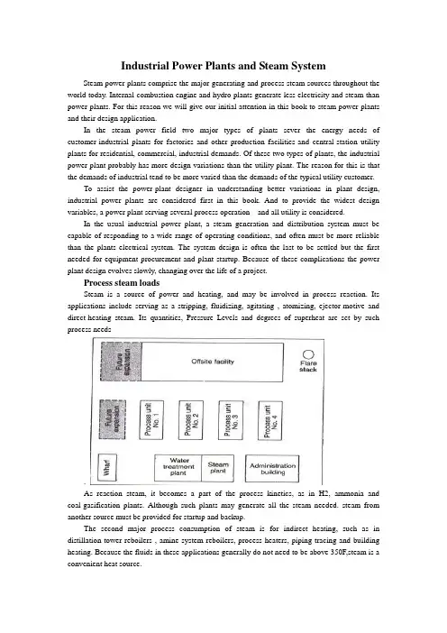
Industrial Power Plants and Steam SystemSteam power plants comprise the major generating and process steam sources throughout the world today. Internal-combustion engine and hydro plants generate less electricity and steam than power plants. For this reason we will give our initial attention in this book to steam power plants and their design application.In the steam power field two major types of plants sever the energy needs of customer-industrial plants for factories and other production facilities-and central-station utility plants for residential, commercial, industrial demands. Of these two types of plants, the industrial power plant probably has more design variations than the utility plant. The reason for this is that the demands of industrial tend to be more varied than the demands of the typical utility customer.To assist the power-plant designer in understanding better variations in plant design, industrial power plants are considered first in this book. And to provide the widest design variables, a power plant serving several process operation and all utility is considered.In the usual industrial power plant, a steam generation and distribution system must be capable of responding to a wide range of operating conditions, and often must be more reliable than the plants electrical system. The system design is often the last to be settled but the first needed for equipment procurement and plant startup. Because of these complications the power plant design evolves slowly, changing over the life of a project.Process steam loadsSteam is a source of power and heating, and may be involved in process reaction. Its applications include serving as a stripping, fluidizing, agitating , atomizing, ejector-motive and direct-heating steam. Its quantities, Pressure Levels and degrees of superheat are set by such process needs.As reaction steam, it becomes a part of the process kinetics, as in H2, ammonia and coal-gasification plants. Although such plants may generate all the steam needed. steam from another source must be provided for startup and backup.The second major process consumption of steam is for indirect heating, such as in distillation-tower reboilers , amine-system reboilers, process heaters, piping tracing and building heating. Because the fluids in these applications generally do not need to be above 350F,steam is a convenient heat source.Again, the quantities of steam required for the services are set by the process design of the facility. There are many options available to the process designer in supplying some of these low-level heat requirements, including heat-exchange system , and circulating heat-transfer-fluid systems, as well as system and electricity. The selection of an option is made early in the design stage and is based predominantly on economic trade-off studies.Generating steam from process heat affords a means of increasing the overall thermal efficiency of a plant. After providing for the recovery of all the heat possible via exchanges, the process designer may be able to reduce cooling requirements by making provisions for the generation of low-pressure(50-150 psig)steam. Although generation at this level may be feasible from a process-design standpoint, the impact of this on the overall steam balance must be considered, because low-pressure steam is excessive in most steam balances, and the generation of additional quantities may worsen the design. Decisions of this type call close coordination between the process and utility engineers.Steam is often generated in the convection section of fired process heaters in order to improve a plant’s thermal efficiency. High-pressure steam can be generated in the furnace convection section of process heater, which have radiant heat duty only.Adding a selective –catalytic-reduction unit for the purpose of lowing NOx emissions may require the generation of waste-heat steam to maintain correct operating temperature to the catalytic-reduction unit.Heat from the incineration of waste gases represents still another source of process steam. Waste-heat flues from the CO boilers of fluid-catalytic crackers and from fluid-coking units, for example, are hot enough to provide the highest pressure level in a steam system.Selecting pressure and temperature levelsThe selecting of pressure and temperature levels for a process steam system is based on:(1)moisture content in condensing-steam turbines,(2)metallurgy of the system,(3)turbine water rates,(4)process requirements ,(5)water treatment costs, and(6)type of distribution system.Moisture content in condensing-steam turbines---The selection of pressure and temperature levels normally starts with the premise that somewhere in the system there will be a condensing turbine. Consequently, the pressure and temperature of the steam must be selected so that its moisture content in the last row of turbine blades will be less than 10-13%. In high speed, a moisture content of 10%or less is desirable. This restriction is imposed in order to minimize erosion of blades by water particles. This, in turn, means that there will be a minimum superheat for a given pressure level, turbine efficiency and condenser pressure for which the system can be designed.System mentallurgy- A second pressure-temperature concern in selecting the appropriate steam levels is the limitation imposed by metallurgy. Carbon steel flanges, for example, are limited to a maximum temperature of 750F because of the threat of graphite (carbides) precipitating at grain boundaries. Hence, at 600 psig and less, carbon-steel piping is acceptable in steam distribution systems. Above 600 psig, alloy piping is required. In a 900- t0 1,500-psig steam system, the piping must be either a r/2 carbon-1/2 molybdenum or a l/2 chromium% molybdenum alloyTurbine water rates - Steam requirements for a turbine are expressed as water rate, i.e., lb of steam/bph, or lb of steam/kWh. Actual water rate is a function of two factors: theoretical water rate and turbine efficiency.The first is directly related to the energy difference between the inlet and outlet of a turbine, based on the isentropic expansion of the steam. It is, therefore, a function of the turbine inlet and outlet pressures and temperatures.The second is a function of size of the turbine and the steam pressure at the inlet, and of turbine operation (i.e., whether the turbine condenses steam, or exhausts some of it to an intermediate pressure level). From an energy stand point, the higher the pressure and temperature, the higher the overall cycle efficiency. _Process requirements - When steam levels are being established, consideration must be given to process requirements other than for turbine drivers. For example, steam for process heating will have to be at a high-enough pressure to prevent process fluids from leaking into the steam. Steam for pipe tracing must be at a certain minimum pressure so that low-pressure condensate can be recovered.Water treatment costs - The higher the steam pressure, the costlier the boiler feedwater treatment. Above 600 psig, the feedwater almost always must be demineralized; below 600 psig, soft,ening may be adequate. It may have to be of high quality if the steam is used in the process, such as in reactions over a catalyst bed (e.g., in hydrogen production).Type of distribution system - There are two types of systems: local, as exemplified by powerhouse distribution; and complex, by wluch steam is distributed to many units in a process plant. For a small local system, it is not impractical from a cost standpoint for steam pressures to be in the 600-1,500-psig range. For a large system, maintaining pressures within the 150-600-psig range is desirable because of the cost of meeting the alloy requirements for higher-pressure steam distribution system.Because of all these foregoing factors, the steam system in a chemical process complex or oil refinery frequently ends up as a three-level arrangement. The highest level, 600 psig, serves primarily as a source of power. The intermediate level, 150 psig, is ideally suitable for small emergency turbines, tracing off the plot, and process heating. The low level, normally 50 psig, can be used for heating services, tracing within the plot, and process requirements. A higher fourth level normally not justified, except in special cases as when alarge amount ofelectric power must be generated.Whether or not an extraction turbine will be included in the process will have a bearing on the intermediate-pressure level selected, because the extraction pressure should be less than 50% of the high-pressure level, to take into account the pressure drop through the throttle valve and the nozzles of the high-pressure section of' the turbine.Drivers for pumps and compressorsThe choice between a steam and an electric driver for a particular pump or compressor depends on a number of things, including the operational philosophy. In the event of a power failure, it must be possible to shut down a plant orderly and safely if normal operation cannot be continued. For an orderly and safe shutdown, certain services must be available during a power failure: (1) instrument air, (2) cooling water, (3) relief and blow down pump out systems, (4) boiler feedwater pumps, (5) boiler fans, (6) emergency power generators, and (7) fire water pumps.These services are normally supplied by steam or diesel drivers because a plant's steam or diesel emergency system is considered more reliable than an electrical tie-line.The procedure for shutting down process units must be analyzed for each type of processplant and specific design. In general, the following represent the minimum services for which spare pumps driven by steam must be provided: column reflux, bottoms and purge-oil circulation, and heater charging. Most important is to maintain cooling; next, to be able to safely pump the plant's inventory into tanks.Driver selection cannot be generalized; a plan and procedure must be developed for each process unit.The control required for a process is at times another consideration in the selection of a driver. For example, a compressor may be controlled via flow or suction pressure. The ability to vary driver speed, easily obtained with a steam turbine, may be basis for selecting a steam driver instead of a constant-speed induction electric motor. This is especially important when the molecular weight of the gas being compressed may vary, as in catalytic-cracking and catalytic-reforming processes.In certain types of plants, gas flow must be maintained to prevent uncontrollable high-temperature excursions during shutdown. For example, hydrocrackers are purged of heavy hydrocarbon with recycle gas to prevent the exothermic reactions from producing high bed temperatures. Steam-driven compressors can do this during a power failure.Each process operation must be analyzed from such a safety viewpoint when selecting drivers for critical equipment. The size of a relief and blowdown system can be reduced by installing steam drivers. In most cases, the size of such a system is based on a total power failure. If heat-removal powered by steam drivers, the relief system can be smaller. For example, a steam driver will maintain flow in the pump-around circuit for removing heat from a column during a power failure, reducing the relief load imposed on the flare system.Equipment support services (such as lubrication and sea-oil systems for compressors) that could be damaged during a loss of power should also be powered by steam drivers.Driver size can also be a factor. An induction electric motor requires large starting currents - typically six times the normal load. The drop in voltage caused by the startup of such a motor imposes a heavy transient demand on the electrical distribution system. For this reason, drivers larger than 10,000 hp are normally steam turbines, although synchronous motors as large as 25,000 hp are used.The reliability of life-support facilities - e.g., building heat, potable water, pipe tracing, emergency lighting-during power failures is of particular concern mates. In such a case, at least one boiler should be equipped with steam-driven auxiliaries to provide these services.Lastly, steam drivers are also selected for the purpose of balancing steam systems and avoiding large amounts of letdown between steam levels. Such decisions regarding drivers are made after the steam balances have been refined and the distribution system has been fully defined. There must be sufficient flexibility to allow balancing the steam system under all operating conditions.Selecting steam driversAfter the number of steam drivers and their services have been established, the utility, or process engineer will estimate the steam consumption for making the steam balance.The standard method of doing this is to use the isentropic expansion of steam correeted for turbine efficiency.Actual steam consumption by a turbine is determined via:SR = (TSR)(bhp)/EHere, SR = actual steam rate, lb/h; TSR = theoretical steam rate, lb/hr/bhp ; bhp = turbine brake horsepower; and E = turbine efficiency.When exhaust steam can be used for process heating, the highest thermodynamic efficiency can be achieved by means of backpressure turbines. Large drivers, which are of high efficiency and require low theoretical steam rates, are normally supplied by the high-pressure header, thus minimizing steam consumption.Small turbines that operate only in emergencies can be allowed to exhaust to atmosphere. Although their water rates are poor, the water lost in short-duration operations may not represent a significant cost. Such turbines obviously play a small role in steam balance planning.Constructing steam balancesAfter the process and steam-turbine demands have been established, the next step is to construct a steam balance for the chemical complex or oil refinery. A sample balance is shown in Fig. 1-4. It shows steam production and consumption, the header systems, letdown stations, and boiler plant. It illustrates a normal (winter) case.It should be emphasized that there is not one balance but a series, representing a variety of operating modes. The object of the balances is to determine the design basis for establishing boiler she, letdown stations and deaerator capacities, boiler feedwater requirements, and steam flows in various parts of the system.The steam balance should cover the following operating modes: normal, all units operating; winter and summer conditions; shutdown of major units; startup of major units; loss of largest condensate source; power failure with flare in service; loss of large process steam generators; and variations in consumption by large steam users.From 50 t0 100 steam balances could be required to adequately cover all the major impacts on the steam system of a large complex.At this point, the general basis of the steam system design should have been developed by the completion of the following work:1. All significant loads have been examined, with particular attention focused on those for which there is relatively little design freedom - i.e., reboilers, sparing steam for process units, large turbines required because of electric power limitation and for shutdown safety.2. Loads have been listed for which the designer has some liberty in selecting drivers. These selections are based on analyses of cost competitiveness.3. Steam pressure and temperature levels have been established.4. The site plan has been reviewed to ascertain where it is not feasible to deliver steam or recover condensate, because piping costs would be excessive.5. Data on the process units are collected according to the pressure level and use of steam - i.e., for the process, condensing drivers and backpressure drivers.6. After Step 5, the system is balanced by trial-and-error calculations or computerized techniques to determine boiler, letdown, deaerator and boiler feedwater requirements.7. Because the possibility of an electric power failure normally imposes one of the major steam requirements, normal operation and the eventuality of such a failure must both be investigated, as a minimum.Checking the design basisAfter the foregoing steps have been completed, the following should be checked:Boiler capacity - Installed boiler capacity would be the maximum calculated (with an allowance of l0-20% for uncertainties in the balance), corrected for the number of boilers operating (and on standby).The balance plays a major role in establishing normal-case boiler specifications, both number and size. Maximum firing typically is based on the emergency case. Normal firing typically establishes the number of boilers required, because each boiler will have to be shut down once a year for the code-required drum inspection. Full-firing levels of the remaining boilers will be set by the normal steam demand. The number of units required (e.g., three 50% units, four 33%units, etc.) in establishing installed boiler capacity is determined from cost studies. It is generally considered double-jeopardy design to assume that a boiler will be out of service during a power failure.Minimum boiler turndown - Most fuel-fired boilers can be operated down to approximately 20% of the maximum continuous rate. The maximum load should not be expected to be below this level.Differences between normal and maximum loads –If the maximum load results from an emergency (such as power failure), consideration should be given to shedding process steam loads under this condition in order to minimize in- stalled boiler capacity. However, the consequences of shedding should be investigated by the process designer and the operating engineers to ensure the safe operation of the entire process.Low-level steam consumption - The key to any steam balance is the disposition of low-level steam. Surplus low-level steam can be reduced only by including more condensing steam turbines in the system, or devising more process applications for it, such as absorption refrigeration for cooling process streams and ranking-cycle systems for generating power. In general, balancing the supply and consumption of low-level steam is a critical factor in the design of the steam system.Quantity of steam at pressure-reducing stations - Because useful work is not recovered from the steam passing through a pressure-reducing station, such flow should be kept at a minimum. In the Fig. 1-5 150/50-psig station, a flow of only 35,000 lb/h was established as normal for this steam balance case (normal, winter). The loss of steam users on the 50-psig systems should be considered, particularly of the large users, because a shutdown of one may demand that the 150/50-psig station close off beyond its controllable limit. If this happened, the 50-psig header would be out of control, and an immediate-pressure buildup in the header wouldbegin, setting off the safety relief valves.The station's full-open capacity should also be checked to ensure that it can make up any 50-psig steam that may be lost through the shutdown of a single large 50-psig source (a turbine sparing a large electric motor, for example}. It would be undesirable for the station to be sized so that it opens more than 80%. In some cases, range ability requirements may dictate two valves (one small and one large).Intermediate pressure level - If large steam users or suppliers may come on stream or go off steam, the normal(day-to-day) operation should be checked. No such change in normal operation should result in a significant upset (e.g.,relief valves set off, or the system pressure control lost).If a large load is lost, the steam supply should be reduced by the letdown-station. If the load suddenly increases, the 600/150-psig station must be able of supplying the additional steam. If steam generated via the process disappears, the station must be capable of making up theload. If150-psig steam is generated unexpectedly, the 600/150-psig station must be able to handle the cutback.The important point here is that where the steam flow could rise t0 700,000 lb/h, this flow should be reduced by a cutback at the 600/150-psig station, not by an increase in the flow to the lower-pressure level, because this steam would have nowhere to go. The normal (600/150-psig) letdown station must be capable of handling some of the negative load swings, even though, overall, this letdown needs to be kept to a minimum.On the other hand, shortages of steam at the 150-psig level can be made up relatively easily via the 600/150-psig station. Such shortages are routinely small in quantity or duration, or both-(startup, purging, electric drive maintenance, process unit shutdown, etc.)High-pressure level - Checking the high-pressure level is generally more straightforward because rate control takes place directly at the boilers. Firing can be increased or lowered to accommodate a shortage or surplus.Typical steam-balance casesThe Fig. 1-4 steam balance represents steady-state condition, winter operation, all process units operating, and no significant unusual demands for steam.An analysis similar to the foregoing might also be required for the normal summertime case, in which a single upset must not jeopardize control but the load may be less (no tank heating, pipe tracing, etc.)The balance representing an emergency (e.g., loss of electric power) is significant. In this case, the pertinent test point is the system's ability to simply weather the upset, not to maintain normal, stable operation. The maximum relief pressure that would develop in any of the headers represents the basis for sizing relief valves. The loss of boiler feed water or condensate return, or both, could result in a major upset, or even a shutdown.Header pressure control during upsetsAt the steady-state conditions associated with the multiplicity of balances, boiler capacity can be adjusted to meet user demands. However, boiler load cannot be changed quickly to accommodate a sharp upset. Response rate is typically limited to 20% of capacity per minute. Therefore, other elements must be relied on to control header pressures during transient conditions.The roles of several such elements in controlling pressures in the three main headers during transient conditions are listed in Table l-3. A control system having these elements will result in a steam system capable of dealing with the transient conditions experienced in moving from one balance point to another.Tracking steam balancesBecause of schedule constraints, steam balances and boiler size are normally established early in the design stage. These determinations are based on assumptions regarding turbine efficiencies, process steam generated in waste-heat furnaces, and other quantities of steam that depend on purchased equipment. Therefore, a sufficient number of steam balances should be tracked through the design period to ensure that the equipment purchased will satisfy the original design concept of the steam system.This tracking represents an excellent application for a utility data-base system and a system linear programming model. During the course of the mechanical design of a large "grass roots" complex, 40 steam balances were continuously updated for changes in steam loads via such an application.Cost tradeoffsTo design an efficient but least-expensive system, the designer ideally develops a total minimum-cost curve – which incorporates all the pertinent costs related to capital expenditures, installation, fuel, utilities, operations and maintenance-and performs a cost study of the final system. However, because the designer is under the constraint of keeping to a project schedule, major, highly expensive equipment must be ordered early in the project, when many key parts of the design puzzle are not available (e.g., a complete load summary, turbine water rates, equipment efficiencies and utility costs).A practical alternative is to rely on comparative-cost estimates, as are conventionally used in assisting with engineering decision points. This approach is particularly useful in making early equipment selections when fine-tuning is not likely to alter decisions, such as regarding the number of boilers required, whether boilers should be shop-fabricated or field-erected, and the practicality of generating steam from waste heat or via cogeneration.The significant elements of a steam-system cost-comparative study are costs for: equipment and installation; ancillaries (i.e., miscellaneous items required to support the equipment,such as additional stacks, upgraded combustion control, more extensive blowdown facilities, etc.); operation(annual); maintenance (annual); and utilities.The first two costs may be obtained from in-house data or from vendors. Operational and maintenance costs can be factored from the capital cost for equipment based on an assessment of the reliability of the purchased equipment.Utility costs are generally the most difficult to establish at an early stage because sources frequently depend on the site of the plant. Some examples of such costs are: purchased fuel gas - $5.35/million Btu, raw water - $0.60/1,000 gal, electricity - $0.07{kWh, and demineralized boiler feedwater -$1.50/1,000 gal. The value of steam at the various pressureLevels can be developed [5J.Let it be further assumed that the emergency balance requires 2,200,000 lb/h of steam (all boilers available). Listed in Table 1 4 are some combinations of boiler installations that meet the design conditions previously stipulated.Table l-4 indicates that any of the several combinations of power-boiler number and size could meet both normal and emergency demand. Therefore, a comparative-cost analysis would be made to assist in making an early decision regarding the number and size of the power boilers.(Table l-4 is based on field-erected, industrial-type boiler Conventional sizing of this type of boiler might range from 100,000 lb/h through 2,000,000 lb/h for each.)An alternative would be the packaged boiler option (although it does not seem practical at this load level. Because it is shop-fabricated, this type of boiler affords a significant saving in terms of field installation cost. Such boilers are available up to a nominal capacity of 100,000 lb/h, with some versions up t0 250,000 lb7h.Selecting turbine water rate i.e., efficiency) represents another major cost concern. Beyond the recognized payout period (e.g., 3 years), the cost of drive steam can be significant in comparison with the equipment capital cost. The typical 30% efficiency ofthe medium-pressure backpressure turbine can be boosted significantly.Driver selections are frequently made with the help of cost-tradeoff studies, unless overriding considerations preclude a drive medium. Electric pump drives are typically recommended on the basis of such studies.Steam tracing has long been the standard way of winterizing piping, not only because of its history of successful performance but also because it is an efficient way to use low-pressure steam.Design consideratonsAs the steam system evolves, the designer identifies steam loads and pressure levels, locates steam loads, checks safety aspects, and prepares cost-tradeoff studies, in order to provide low-cost energy safely, always remaining aware of the physical entity that will arise from the design.How are design concepts translated into a design document? And what basic guidelines will ensure that the physical plant will represent what was intended conceptually?Basic to achieving these ends is the piping and instrument diagram (familiar as the P&ID). Although it is drawn up primarily for the piping designers benefit, it also plays a major role in communicating to the instrumentation designer the process-control strategy, as well as in conveying specialty information to electrical, civil, structural, mechanical and architectural engineers. It is the most important document for representing the specification of the steam。

java毕业设计中英文翻译篇一:JAVA外文文献+翻译Java and the InternetIf Java is, in fact, yet another computer programming language, you may question why it is so important and why it is being promoted as a revolutionary step in computer programming. The answer isn’t immediately obvious if you’re coming from a traditional programming perspective. Although Java is very useful for solving traditional stand-alone programming problems, it is also important because it will solve programming problems on the World Wide Web.1. Client-side programmingThe Web’s initial server-browser design provided for interactive content, but the interactivity was completely provided by the server. The server produced static pages for the client browser, which would simply interpret and display them. Basic HTML contains simple mechanisms for data gathering: text-entry boxes, check boxes, radio boxes, lists and drop-down lists, as well as a button that can only be programmed to reset the data on the form or “submit” the data on the form backto the server. This submission passes through the Common Gateway Interface (CGI) provided on all Web servers. The text within the submission tells CGI what to do with it. The most common action is to run a program located on the server in a directory that’s typically called “cgi-bin.” (If you watch the address window at the top of your browser when you push a button on a Web page, you can sometimes see “cgi-bin” within all the gobbledygook there.) These programs can be written in most languages. Perl is a common choice because it is designed for text manipulation and is interpreted, so it can be installed on any server regardless of processor or operating system. Many powerful Web sites today are built strictly on CGI, and you can in fact do nearly anything with it. However, Web sites built on CGI programs can rapidly become overly complicated to maintain, and there is also the problem of response time. The response of a CGI program depends on how much data mustbe sent, as well as the load on both the server and the Internet. (On top of this, starting a CGI program tends to be slow.) The initial designers of the Web didnot foresee how rapidly this bandwidth would be exhausted for the kinds of applications people developed. For example, any sort of dynamic graphing is nearly impossible to perform with consistency because a GIF file must be created and moved from the server to the client for each version of the graph. And you’ve no doubt had direct experience with something as simple as validating the data on an input form. You press the submit button on a page; the data is shipped back to the server; the server starts a CGI program that discovers an error, formats an HTML page informing you of the error, and then sends the page back to you; you must then back up a page and try again. Not only is this slow, it’s inelegant.The solution is client-side programming. Most machines that run Web browsers are powerful engines capable of doing vast work, and with the original static HTML approach they are sitting there, just idly waiting for the server to dish up the next page. Client-side programming means that the Web browser is harnessed to do whatever work it can, and the result for the user is a much speedier and more interactive experience atyour Web site.The problem with discussions of client-side programming is that they aren’t very different from discussions of programming in general. The parameters are almost the same, but the platform is different: a Web browser is like a limited operating system. In the end, you must still program, and this accounts for the dizzying array of problems and solutions produced by client-side programming. The rest of this section provides an overview of the issues and approaches in client-side programming.2.Plug-insOne of the most significant steps forward in client-side programming is the development of the plug-in. This is a way for a programmer to add new functionality to the browser by downloading a piece of code that plugs itself into the appropriate spot in the browser. It tells the browser “from now on you can perform this new activity.” (You need to download the plug-in only once.) Some fast and powerful behavior is added to browsers via plug-ins, but writing a plug-in is not a trivial task, and isn’t something you’d wantto do as part of the process of building a particular site. The value of the plug-in for client-side programming is that it allows an expert programmer to develop a new language and add that language to a browser without the permission of the browser manufacturer. Thus, plug-ins provide a “back door”that allows the creation of new client-side programming languages (although not all languages are implemented as plug-ins).3.Scripting languagesPlug-ins resulted in an explosion of scripting languages. With a scripting language you embed the source code for your client-side program directly into the HTML page, and the plug-in that interprets that language is automatically activated while the HTML page is being displayed. Scripting languages tend to be reasonably easy to understand and, because they are simply text that is part of an HTML page, they load very quickly as part of the single server hit required to procure that page. The trade-off is that your code is exposed for everyone to see (and steal). Generally, however, you aren’t doing amazingly sophisticatedthings with scripting languages so this is not too much of a hardship.This points out that the scripting languages used inside Web browsers are really intended to solve specific types of problems, primarily the creation of richer and more interactive graphical user interfaces (GUIs). However, a scripting language might solve 80 percent of the problems encountered in client-side programming. Your problems might very well fit completely within that 80 percent, and since scripting languages can allow easier and faster development, you should probably consider a scripting language before looking at a more involved solution such as Java or ActiveX programming.The most commonly discussed browser scripting languages are JavaScript (which has nothing to do with Java; it’s named that way just to grab some of Java’s marketing momentum), VBScript (which looks like Visual Basic), andTcl/Tk, which comes from the popular cross-platform GUI-building language. There are others out there, and no doubt more in development.JavaScript is probably the most commonly supported. It comes built into both Netscape Navigator and the Microsoft Internet Explorer (IE). In addition, there are probably more JavaScript books available than there are for the other browser languages, and some tools automatically create pages using JavaScript. However, if you’re already fluent in Visual Basic or Tcl/Tk, you’ll be more productive using those scripting languages rather than learning a new one. (You’ll have your hands full dealing with the Web issues already.)4.JavaIf a scripting language can solve 80 percent of the client-side programming problems, what about the other 20 percent—the “really hard stuff?” The most popular solution today is Java. Not only is it a powerful programming language built to be secure, cross-platform, and international, but Java is being continually extended to provide language features and libraries that elegantly handle problems that are difficult in traditional programming languages, such as multithreading, database access, network programming, and distributed computing. Java allowsclient-side programming via the applet.An applet is a mini-program that will run only under a Web browser. The applet is downloaded automatically as part of a Web page (just as, for example, a graphic is automatically downloaded). When the applet is activated it executes a program. This is part of its beauty—it provides you with a way to automatically distribute the client software from the server at the time the user needs the client software, and no sooner. The user gets the latest version of the client software without fail and without difficult reinstallation. Because of the way Java is designed, the programmer needs to create only a single program, and that program automatically works with all computers that have browsers with built-in Java interpreters. (This safely includes the vast majority of machines.) Since Java is a full-fledged programming language, you can do as much work as possible on the client before and after making requests of theserver. For example, you won’t need to send a request form across the Internet to discover that you’ve gotten a date or some other parameter wrong, and yourclient computer can quickly do the work of plotting data instead of waiting for the server to make a plot and ship a graphic image back to you. Not only do you get the immediate win of speed and responsiveness, but the general network traffic and load on servers can be reduced, preventing the entire Internet from slowing down.One advantage a Java applet has over a scripted program is that it’s in compiled form, so the source code isn’t available to the client. On the other hand, a Java applet can be decompiled without too much trouble, but hiding your code is often not an important issue. Two other factors can be important. As you will see later in this book, a compiled Java applet can comprise many modules and take multiple server “hits” (accesses) to download. (In Java 1.1 and higher this is minimized by Java archives, called JAR files, that allow all the required modules to be packaged together and compressed for a single download.) A scripted program will just be integrated into the Web page as part of its text (and will generally be smaller and reduce server hits). This could be important to the responsiveness of your Website. Another factor is the all-important learning curve. Regardless of what you’ve heard, Java is not a trivial language to learn. If you’re a Visual Basic programmer, moving to VBScript will be your fastest solution, and since it will probably solve most typical client/server problems you might be hard pressed to justify learning Java. If you’re experienced with a scripting language you will certainly benefit from looking at JavaScript or VBScript before committing to Java, since they might fit your needs handily and you’ll be more productive sooner.to run its applets withi5.ActiveXTo some degree, the competitor to Java is Microsoft’s ActiveX, although it takes a completely different approach. ActiveX was originally a Windows-only solution, although it is now being developed via an independent consortium to become cross-platform. Effectively, ActiveX says “if your program connects to篇二:JAVA思想外文翻译毕业设计文献来源:Bruce Eckel. Thinking in Java [J]. Pearson Higher Isia Education,XX-2-20.Java编程思想 (Java和因特网)既然Java不过另一种类型的程序设计语言,大家可能会奇怪它为什么值得如此重视,为什么还有这么多的人认为它是计算机程序设计的一个里程碑呢?如果您来自一个传统的程序设计背景,那么答案在刚开始的时候并不是很明显。
轨道交通学院毕业设计(论文)外文翻译题目:列车车载的直流恒流源的设计专业电子信息工程班级10115111学号1011511137姓名赵士伟指导教师陈文2014 年3 月 3 日本文摘自:IEEE TRANSACTIONS ON INDUSTRY AND GENERAL APPLICATIONS VOL. IGA-2, NO.5 SEPT/OCT 1966Highly Regulated DC Power Supplies Abstract-The design and application of highly regulated dc power supplies present many subtle, diverse, and interesting problems. This paper discusses some of these problems (especially inconnection with medium power units) but emphasis has been placed more on circuit economics rather than on ultimate performance.Sophisticated methods and problems encountered in connection with precision reference supplies are therefore excluded. The problems discussed include the subjects of temperature coefficient,short-term drift, thermal drift, transient response degeneration caused by remote sensing, and switching preregualtor-type units and some of their performance characteristics.INTRODUCTIONANY SURVEY of the commercial de power supply field will uncover the fact that 0.01 percent regulated power supplies are standard types and can be obtained at relatively low costs. While most users of these power supplies do not require such high regulation, they never-theless get this at little extra cost for the simple reason that it costs the manufacturer very little to give him 0.01 percent instead of 0.1 percent. The performance of a power supply, however, includes other factors besides line and load regulation. This paper will discuss a few of these-namely, temperature coefficient, short-term drift, thermal drift, and transient response. Present medium power dc supplies commonly employ preregulation as a means of improving power/volume ratios and costs, but some characteristics of the power supply suffer by this approach. Some of the short-comings as well as advantages of this technology will be examined.TEMPERATURE COEFFICIENTA decade ago, most commercial power supplies were made to regulation specifications of 0.25 to 1 percent. The reference elements were gas diodes having temperature coefficients of the order of 0.01 percent [1]. Consequently, the TC (temperature coefficient) of the supply was small compared to the regulation specifications and often ignored. Today, the reference element often carries aTC specification greater than the regulation specification.While the latter may be improved considerably at little cost increase, this is not necessarily true of TC. Therefore,the use of very low TC zener diodes, matched differential amplifier stages, and low TC wire wound resistors must be analyzed carefully, if costs are to be kept low.A typical first amplifier stage is shown in Fig. 1. CRI is the reference zener diode and R, is the output adjustment potentiometer.Fig. 1. Input stage of power supply.Fig. 2. Equivalent circuit of zener reference.Let it be assumed that e3, the output of the stage, feedsadditional differential amplifiers, and under steady-state conditions e3 = 0. A variation of any of the parameters could cause the output to drift; while this is also true of the other stages, the effects are reduced by the gain of all previous stages. Consequently, the effects of other stages will be neglected. The following disculssion covers the effects of all elements having primary and secondary influences on the overall TC.Effect of R3The equivalent circuit of CRI -R3 branch is shown in Fig. 2. The zener ha's been replaced with its equivalent voltage source E/' and internal impedance R,. For high gain regulators, the input of the differential amplifier will have negligible change with variations of R3 so thatbefore and after a variation of R3 is made.If it is further assumed that IB << Iz; then from (1)Also,Eliminating I, from (2b),andNow, assuming thatthen,Equation (2b) can also be writtenThe Zener DiodeThe zener diode itself has a temperature coefficient andusually is the component that dominates the overall TCof the unit. For the circuit of Fig. 1, the TC ofthe circuit describes, in essence, the portion of the regulator TC contributed by the zener. If the bridge circuit shown in Fig. 1 were used in conjunction with a dropping resistor so that only a portion of the output voltage appeared across the bridge circuit shown, the TC of the unit and the zener would be different. Since the characteristic of zeners is so well known and so well described in the literature, a discussion will not be given here [2].Variation of Base-Emitter VoltagesNot only do the values of V,, of the differential am-plifier fail to match, but their differentials with tem perature also fail to match. This should not, however,suggest that matched pairs are required. The true reference voltage of Fig. 1 is not the value E,, but E, + (Vie, -Vbe2)-Since, for most practical applicatioinsthe TC of the reference will be the TC of the zener plusConsidering that it is difficult to obtain matched pairs that have differentials as poor as 50 V/°C, it becomes rather apparent that, in most cases, a matched pair bought specifically for TC may be overdesigning.Example 2: A standard available low-cost matched pair laims 30AV/°C. In conjunction with a 1N752, the ontribution to the overall TC would beTests, performed by the author on thirteen standard germanium signal transistors in the vicinity of room temperature and at a collector current level of 3 mA,indicated that it is reasonable to expect that 90 to 95 percent of the units would have a base-emitter voltage variation of -2.1 to -2.4 mV/°C. Spreads of this magnitude have also been verified by others (e.g., Steiger[3]). The worst matching of transistors led to less than 400 ,V/°C differential. In conjunction with a 1N752,even this would give a TC of better than 0.007%/0C.Variation of Base CurrentsThe base current of the transistors is given byA variation of this current causes a variation in signal voltage at the input to the differential amplifier due to finite source impedances. Matching source impedances is not particularly desirable, since it reduces the gain of the system and requires that transistors matched for I,o and A be used. Hunter [4 ] states that the TC of a is in the range of +0.2%/0C to -0.2%7/'C and that 1,, may be approximated bywhere Ao is the value at To.β is also temperature dependent and Steiger [3] experimentally determined the variation to be from about 0.5%/°C to 0.9%/0C.And,Fig. 3. Input circuit of Q2.The current AIB flows through the source impedance per Fig. 3. The drops in the resistance string, however, are subject to the constraint that EB (and AEB) are determined by the zener voltage and the base-emitter drops of Q1 and Q2. Consequently, if in going from temperature T1to T2 a change AEB occurs,The change in output voltage isAndExample 3: For Q2 (at 25°C)(see Example 1)∴Variation of R,The effects of a variation of the TC between RIA and RIB is sufficiently self-evident so that a discussion of the contribution is not included.SHORT-TERM DRIFTThe short-term drift of a supply is defined by the National Electrical Manufacturers Association (NEMA) as "a change in output over a period of time, which change is unrelated to input, environment, or load [5]."Much of the material described in the section on temperature coefficient is applicable here as well. It has been determined experimentally, however, that thermal air drafts in and near thevicinity ofthe powersupplycontributesenormouslyto theshort-termcharacteristics. Thecooling effects of moving air are quite well known, but it is not often recognized that even extremely slow air movements over such devices as zeners and transistors cause the junction temperature of these devices to change rapidly. If the TC of the supply is large compared to the regulation, then large variations in the output will be observed. Units having low TC's achieved by compensation-that is, by canceling out the effects of some omponents by equal and opposite effects of others may still be plagued by these drafts due to the difference in thermal time constants of the elements.Oftentimes, a matched transistor differential amplifier in a common envelope is used for the first amplifier just to equalize and eliminate the difference in cooling effects between the junctions. Approximations to this method include cementing or holding the transistors together, imbedding the transistors in a common metal block, etc. Excellent results were achieved by the author by placing the input stage and zener reference in a separate enclosure. This construction is shown in Fig. 4. The improvement in drift obtained by means of the addition of the metal cover is demonstrated dramatically in Fig. 5.Fig. 5. Short-term drift of a power supply similar to the one shown in Fig. 4 with and without protective covers. The unit was operated without the cover until time tl, when the cover was attached. The initial voltage change following t, is due to a temperaturerise inside the box.Fig. 5. Short-term drift of a power supply similar to the one shown n Fig. 4 withand without protective covers. The unit was operated without the cover until time tl, when the cover was attached. The initial voltage change following t, is due to atemperature rise inside the box.If potentiometers are used in the supply for output adjustment (e.g., RI), care should be used in choosing the value and design. Variations of the contact resistance can cause drift. It is not always necessary, however, to resort to the expense of high-resolution multiturn precision units to obtain low drift. A reduction in range of adjustment, use of low-resistance alloys and low-resolution units which permit the contact arm to rest firmly between turns, may be just as satisfactory. Of course, other considerations should include the ability of both the arms and the wire to resist corrosion. Silicone greases are helpful here. Periodic movement of contact arms has been found helpful in "healing" corroded elements.THERMAL DRIFTNEMA defines thermal drift as "a change in output over a period of time, due to changes in internal ambient temperatures not normally related to environmental changes. Thermal drift is usually associated with changes in line voltage and/or load changes [5]."Thermal drift, therefore, is strongly related to the TC of the supply as well as its overall thermal design. By proper placement of critical components it is possible to greatly reduce or even eliminate the effect entirely. It is not uncommon for supplies of the 0.01 percent(regulation) variety to have drifts of between 0.05 to 0.15 percent for full line or full load variations. In fact, one manufacturer has suggested that anything better than 0.15 percent is good. Solutions to reducing thermal drift other than the obvious approach of improving the TC and reducing internal losses include a mechanical design that sets up a physical and thermal barrier between the critical amplifier components and heat dissipating elements. Exposure to outside surfaces with good ventilation is recommended. With care, 0.01 to 0.05 percent is obtainable.TRANSIENT RESPONSEMost power supplies of the type being discussed have a capacitor across the load terminals. This is used for stabilization purposes and usually determines the dominant time constant of the supply. The presence of this capacitor unfortunately leads to undesirable transient phenomena when the supply is used in the remote sensing mode①. Normally, transistorized power supplies respond in microseconds, but as the author has pointed out [6], the response can degenerate severely in remote sensing .The equivalent circuit is shown in Fig. 6. The leads from the power supply to the load introduce resistance r. Is is the sensing current of the supply and is relatively constant.Under equilibrium conditions,A sudden load change will produce the transient of Fig. 7. The initial "spike" is caused by an inductive surge Ldi/dt; the longer linear discharge following is the resultof the capacitor trying to discharge (or charge). The discharge time iswhereandThe limitations of I,, are usually not due to available drive of the final amplifier stages but to other limitations, current limiting being the most common. Units using pre regulators of the switching type (transistor or SCR types) should be looked at carefully if the characteristics mentioned represent a problem.①Remote sensing is the process by which the power supply senses voltage directly at the load.Fig. 6. Output equivalent circuit at remote sensing.Fig. 7. Transient response, remote sensing.Fig. 8. Block diagram.Preregulated supplies are used to reduce size and losses by monitoring and controlling the voltage across the class-A-type series passing stage (Fig. 8). Since the main regulator invariably responds much quicker than the preregulator, sufficient reserve should always be built into the drop across the passing stage. Failure to provide this may result in saturation of the passing stage when load is applied, resulting in a response time which is that of the preregulator itself.SWITCHING PREREGULATOR-TYPE UNITS The conventional class-A-type transistorized power supply becomes rather bulky, expensive, and crowded with passing stages, as the current and power level of the supply increases. The requirement of wide output adjustment range, coupled with the ability of the supply to be remotely programmable, aggravates the condition enormously. For these reasons the high-efficiency switching regulator has been employed as a preregulator in commercial as well as military supplies for many years. The overwhelming majority of the supplies used silicon controlled rectifiers as the control element. For systems operating from 60-cycle sources, this preregulator responds in 20 to 50 ms.Recent improvements in high-voltage, high-power switching transistors has made the switching transistor pproach more attractive. This system offers a somewhat lower-cost, lower-volume approach coupled with a submillisecond response time. This is brought about by a high switching rate that is normally independent of line frequency. The switching frequency may be fixed, a controlled variable or an independent self-generated (by the LC filter circuit) parameter [7], [8]. Faster response time is highly desirable since it reduces the amount of reserve voltage required across the passing stage or the amount of (storage) capacity required in the preregulator filter.A transistor suitable for operating as a power switch has a high-current, high-voltage rating coupled with low leakage current. Unfortunately, these characteristics are achieved by a sacrifice in thermal capacity, so that simultaneous conditions of voltage and current leading to high peak power could be disastrous. It therefore becomes mandatory to design for sufficient switch drive during peak load conditions and also incorporate current-limiting or rapid overload protection systems.Commercial wide-range power supplies invariably have output current limiting, but this does not limit the preregulator currents except during steady-state load conditions (including short circuits). Consider, for example, a power supply operating at short circuit and the short being removed suddenly. Referring to Fig. 8, the output would rise rapidly, reduce the passing stage voltage, and close the switching transistor. The resulting transient extends over many cycles (switching rate) so that the inductance of the preregulator filter becomes totally inadequate to limit current flow. Therefore, the current will rise until steady state is resumed, circuit resistance causes limiting, or insufficient drive causes the switch to come out of saturation. The latter condition leads to switch failure.Other operating conditions that would produce similar transients include output voltage programming and initial turn-on of the supply. Momentary interruption of input power should also be a prime consideration.One solution to the problem is to limit the rate of change of voltage that can appear across the passing stage to a value that the preregulator can follow. This can be done conveniently by the addition of sufficient output capacitance. This capacitance inconjunction with the current limiting characteristic would produce a maximum rate of change ofwhereC0 = output capacity.Assuming that the preregulator follows this change and has a filter capacitor Cl, then the switch current isDuring power on, the preregulator reference voltage rise must also be limited. Taking this into account,whereER = passing stage voltageTl = time constant of reference supply.The use of SCR's to replace the transistors would be a marked improvement due to higher surge current ratings, but turning them off requires large energy sources. While the gate turn-off SCR seems to offer a good compromise to the overall problem, the severe limitations in current ratings presently restrict their use.REFERENCES[1] J. G. Truxal, Control Engineer's Handbook. New York: McGrawHill, 1958, pp. 11-19.[2] Motorola Zener Diode/Rectifier Handbook, 2nd ed. 1961.[3] W. Steiger, "A transistor temperature analysis and its applica-tion to differential amplifiers," IRE Trans. on Instrumentation,vol. 1-8, pp. 82-91, December 1959.[4] L. P. Hunter, Handbook of Semi-Conductor Electronics. NewYork: McGraw Hill, 1956, p. 13-3.[5] "Standards publication for regulated electronic dc powersupplies," (unpublished draft) Electronic Power Supply Group,Semi-Conductor Power Converter Section, NEMA.[6] P. Muchnick, "Remote sensing of transistorized power sup-plies," Electronic Products, September 1962.[7] R. D. Loucks, "Considerations in the design of switching typeregulators," Solid State Design, April 1963.[8] D. Hancock and B. Kurger, "High efficiency regulated powersupply utilizing high speed switching," presented at the AIEEWinter General Meeting, New York, N. Y., January 27-February 1, 1963.[9] R. D. Middlebrook, Differential Amplifiers. New York: Wiley,1963.[10] Sorensen Controlled Power Catalog and Handbook. Sorensen,Unit of Raytheon Company, South Norwalk, Conn.With the rapid development of electronic technology, application field of electronic system is more and more extensive, electronic equipment, there are more and more people work with electronic equipment, life is increasingly close relationship. Any electronic equipment are inseparable from reliable power supply for power requirements, they more and more is also high. Electronic equipment miniaturized and low cost in the power of light and thin, small and efficient for development direction. The traditional transistors series adjustment manostat is continuous control linear manostat. This traditional manostat technology more mature, and there has been a large number of integrated linear manostat module, has the stable performance is good, output ripple voltage small, reliable operation, etc. But usually need are bulky and heavy industrial frequency transformer and bulk and weight are big filter.In the 1950s, NASA to miniaturization, light weight as the goal, for a rocket carrying the switch power development. In almost half a century of development process, switch power because of its small volume, light weight, high efficiency, wide range, voltage advantages in electric, control, computer, and many other areas of electronic equipment has been widely used. In the 1980s, a computer is made up of all of switch power supply, the first complete computer power generation. Throughout the 1990s, switching power supply in electronics, electrical equipment, home appliances areas to be widely, switch power technology into the rapid development. In addition, large scale integrated circuit technology, and the rapid development of switch power supply with a qualitative leap, raised high frequency power products of, miniaturization, modular tide.Power switch tube, PWM controller and high-frequency transformer is an indispensable part of the switch power supply. The traditional switch power supply is normally made by using high frequency power switch tube division and the pins, such as using PWM integrated controller UC3842 + MOSFET is domestic small power switch power supply, the design method of a more popularity.Since the 1970s, emerged in many function complete integrated control circuit, switch power supply circuit increasingly simplified, working frequency enhances unceasingly, improving efficiency, and for power miniaturization provides the broad prospect. Three end off-line pulse width modulation monolithic integrated circuit TOP (Three switch Line) will Terminal Off with power switch MOSFET PWM controller one package together, has become the mainstream of switch power IC development. Adopt TOP switch IC design switch power, can make the circuit simplified, volume further narrowing, cost also is decreased obviouslyMonolithic switching power supply has the monolithic integrated, the minimalist peripheral circuit, best performance index, no work frequency transformer can constitute a significant advantage switching power supply, etc. American PI (with) company in Power in the mid 1990s first launched the new high frequency switching Power supply chip, known as the "top switch Power", with low cost, simple circuit, higher efficiency. The first generation of products launched in 1994 represented TOP100/200 series, the second generation product is the TOPSwitch - debuted in 1997 Ⅱ. The above products once appeared showed strong vitality and he greatly simplifies thedesign of 150W following switching power supply and the development of new products for the new job, also, high efficiency and low cost switch power supply promotion and popularization created good condition, which can be widely used in instrumentation, notebook computers, mobile phones, TV, VCD and DVD, perturbation VCR, mobile phone battery chargers, power amplifier and other fields, and form various miniaturization, density, on price can compete with the linear manostat AC/DC power transformation module.Switching power supply to integrated direction of future development will be the main trend, power density will more and more big, to process requirements will increasingly high. In semiconductor devices and magnetic materials, no new breakthrough technology progress before major might find it hard to achieve, technology innovation will focus on how to improve the efficiency and focus on reducing weight. Therefore, craft level will be in the position of power supply manufacturing higher in. In addition, the application of digital control IC is the future direction of the development of a switch power. This trust in DSP for speed and anti-interference technology unceasing enhancement. As for advanced control method, now the individual feels haven't seen practicability of the method appears particularly strong,perhaps with the popularity of digital control, and there are some new control theory into switching power supply.(1)The technology: with high frequency switching frequencies increase, switch converter volume also decrease, power density has also been boosted, dynamic response improved. Small power DC - DC converter switch frequency will rise to MHz. But as the switch frequency unceasing enhancement, switch components and passive components loss increases, high-frequency parasitic parameters and high-frequency EMI and so on the new issues will also be caused.(2)Soft switching technologies: in order to improve the efficiency ofnon-linearity of various soft switch, commutation technical application and hygiene, representative of soft switch technology is passive and active soft switch technology, mainly including zero voltage switch/zero current switch (ZVS/ZCS) resonance, quasi resonant, zero voltage/zero current pulse width modulation technology (ZVS/ZCS - PWM) and zero voltage transition/zero current transition pulse width modulation (PWM) ZVT/ZCT - technical, etc. By means of soft switch technology can effectively reduce switch loss and switch stress, help converter transformation efficiency (3)Power factor correction technology (IC simplifies PFC). At present mainly divided into IC simplifies PFC technology passive and active IC simplifies PFC technology using IC simplifies PFC technology two kinds big, IC simplifies PFC technology can improve AC - DC change device input power factor, reduce the harmonic pollution of power grid.(4)Modular technology. Modular technology can meet the needs of the distributed power system, enhance the system reliability.(5)Low output voltage technology. With the continuous development of semiconductor manufacturing technology, microprocessor and portable electronic devices work more and more low, this requires future DC - DC converter can provide low output voltage to adapt microprocessor and power supply requirement of portable electronic devicesPeople in switching power supply technical fields are edge developing related power electronics device, the side of frequency conversion technology, development of switch between mutual promotion push switch power supply with more than two year growth toward light, digital small, thin, low noise and high reliability, anti-interference direction. Switching powersupply can be divided into the AC/DC and DC/DC two kinds big, also have AC/AC DC/AC as inverter DC/DC converter is now realize modular, and design technology and production process at home and abroad, are mature and standardization, and has approved by users, but the AC/DC modular, because of its own characteristics in the process of making modular, meet more complex technology and craft manufacture problems. The following two types of switch power supply respectively on the structure and properties of this.Switching power supply is the development direction of high frequency, high reliability, low consumption, low noise, anti-jamming and modular. Because light switch power, small, thin key techniques are changed, so high overseas each big switch power supply manufacturer are devoted to the development of new high intelligent synchronous rectifier, especially the improvement of secondary devices of the device, and power loss of Zn ferrite (Mn) material? By increasing scientific and technological innovation, to enhance in high frequency and larger magnetic flux density (Bs) can get high magnetic under the miniaturization of, and capacitor is a key technology. SMT technology application makes switching power supply has made considerable progress, both sides in the circuitboard to ensure that decorate components of switch power supply light, small, thin. The high frequency switching power supply of the traditional PWM must innovate switch technology, to realize the ZCS ZVS, soft switch technology has becomethe mainstream of switch power supply technical, and greatly improve the efficiency of switch power. For high reliability index, America's switch power producers, reduce by lowering operating current measures such as junction temperature of the device, in order to reduce stress the reliability of products made greatly increased.Modularity is of the general development of switch power supply trend can be modular power component distributed power system, can be designed to N + 1 redundant system, and realize the capacity expansion parallel. According to switch power running large noise this one defect, if separate the pursuit of high frequency noise will increase its with the partial resonance, and transform circuit technology, high frequency can be realized in theory and can reduce the noise, but part of the practical application of resonant conversion technology still have a technical problem, so in this area still need to carry out a lot of work, in order to make the technology to practional utilization.Power electronic technology unceasing innovation, switch power supply industry has broad prospects for development. To speed up the development of switch power industry in China, we must walk speed of technological innovation road, combination with Chinese characteristics in the joint development path, for I the high-speed development of national economy to make the contribution. The basic principle and component functionAccording to the control principle of switch power to classification, we have the following 3 kinds of work mode:1) pulse width adjustment type, abbreviation Modulation PulseWidth pulse width Modulation (PWM) type, abbreviation for. Its main characteristic is fixed switching frequency, pulse width to adjust by changing voltage 390v, realize the purpose. Its core is the pulse width modulator. Switch cycle for designing filter circuit fixed provided convenience. However, its shortcomings is influenced by the power switch conduction time limit minimum of output voltage cannot be wide range regulation; In addition, the output will take dummy loads commonly (also called pre load), in order to prevent the drag elevated when output voltage. At present, most of the integrated switch power adopt PWM way.2) pulse frequency Modulation mode pulse frequency Modulation (, referred to PulseFrequency Modulation, abbreviation for PFM) type. Its characteristic is will pulse width fixed by changing switch frequency to adjust voltage 390v, realize the purpose. Its core is the pulse frequency modulator. Circuit design to use fixed pulse-width generator to replace the pulse width omdulatros and use sawtooth wave generator voltage? Frequency converter (for example VCO changes frequency VCO). It on voltage stability principle is: when the output voltage Uo rises, the output signal controller pulse width unchanged and cycle longer, make Uo 390v decreases, and reduction. PFM type of switch power supply output voltage range is very wide, output terminal don't meet dummy loads. PWM way and way of PFM respectively modulating waveform is shown in figure 1 (a), (b) shows, tp says pulse width (namely power switch tube conduction time tON), T represent cycle. It can be easy to see the difference between the two. But they have something in common: (1) all use time ratio control (TRC) on voltage stability principle, whether change tp, finally adjustment or T is。

毕业设计英文Graduation DesignFor my graduation design, I have chosen to focus on creating a sustainable and eco-friendly product that promotes a healthy lifestyle. The design is centered around a smart water bottle that tracks and monitors an individual's hydration levels throughout the day.The water bottle is made from recycled materials and has a sleek and ergonomic design, making it easy to carry around. It is equipped with a built-in sensor that measures the amount of water consumed and sends the data to a corresponding mobile app. The app then analyzes the data and provides personalized recommendations for the user's water intake, taking into consideration factors such as age, weight, and physical activity.In addition to tracking how much water is consumed, the water bottle also reminds the user to drink water at regular intervals. This is done through gentle vibrating alerts and notifications on the user's smartphone. The smart water bottle also has a built-in alarm system that alerts the user when they have not consumed enough water during a specified time period, ensuring that they stay hydrated throughout the day.The app also provides a comprehensive analysis of the user's hydration patterns, allowing them to set hydration goals and track their progress over time. It also provides tips and reminders on the importance of staying hydrated and offers suggestions for other healthy habits that can be incorporated into one's daily routine.The smart water bottle also contributes to reducing plastic waste by encouraging users to refill their bottle instead of purchasing single-use plastic bottles. The app includes a feature that helps the user locate nearby water fountains and refill stations, making it convenient and easy to stay hydrated while on-the-go.Overall, my graduation design aims to promote a sustainable and healthy lifestyle by encouraging individuals to stay hydrated and reduce their environmental footprint. By combining technology and design, this smart water bottle provides a practical solution to a common problem while also raising awareness about the importance of hydration and environmental conservation.。

The first dam for which there are reliable records was build on the Nile River sometime before 4000 B.C.It was used to divert the Nile and provide a site for the ancient city of Memphis.The oldest dam still in use is the Almanza Dam in Spain,which was constructed in the sixteenth ceentury.With the passage of time, materials and construction have improved, making possible the erection of such large dams as the Nurek Dam, which is being constructed in the U.S.S.R. On the vaksh River near the border of Afghanistan. This dam will be 1017ft(333m)high, of earth and rock fill. The failure of a dam may cause serious loss of life and property; consequently, the design and maintenance of dams are commonly under government surveillance. In the United States over 30000 dams are under the control of state authorities. The 1972 Federal Dam Safety Act (PL92-367) requires periodic inspections of dams by qualified experts. The failure of the Teton Dam in Idaho in June 1976 added to the concern for dam safety in the United States.1.Type of DamsDams are classified on the basis of the type and materials of construction, as gravity, arch, buttress, and earth. The first three types are usually constructed of concrete. A gravity dam depends on its own weight for stability and it straight in plan although sometimes slightly curved. Arch dams transmit most of the horizontal thrust of the water behind them to the abutments by arch action and have thinner cross sections than comparable gravity dams. Arch dams can be used only in narrow canyons where the walls are capable of withstanding the thrust produced by the arch action. The simplest of the many types of buttresses. Earth dams are embankments of rock or earth with provision for controlling seepage by means of an impermeable core or upstream blanket. More than one type of dam may be included in a single structure. Curved dams may combine both gravity and arch action to achieve stability. Long dams often have a concrete river section containning spollway and sluice gates and earth or rock-fill wing dams for the remainder of their length.The selection of the best type of dam for a given site is a problem in both engineering feasibility and cost. Feasibility is governed by topography, geology and climate. For example, because concrete spalls when subjected to alternate freezing and thawing, arch and buttress dams With thin concrete section are sometimes avoided in areas subject to extreme cold. The relative cost of the various type of dams depends mainly on the availability of construction materials near the site and the accessibility of transportation facilities. Dams are sometimes built in stages with the second or later stages constructed a decade or longer after the stage.The height of a dam is defined as the difference in elevation between the roadway, or spillway crest, and the lowest part of the excayated foundation. However, figures quoted for heights of dams are oftendetemined in other ways. Frequently the height is taken net height above the old riverbed.。
软件工程专业毕业设计外文文献翻译1000字本文将就软件工程专业毕业设计的外文文献进行翻译,能够为相关考生提供一定的参考。
外文文献1: Software Engineering Practices in Industry: A Case StudyAbstractThis paper reports a case study of software engineering practices in industry. The study was conducted with a large US software development company that produces software for aerospace and medical applications. The study investigated the company’s software development process, practices, and techniques that lead to the production of quality software. The software engineering practices were identified through a survey questionnaire and a series of interviews with the company’s software development managers, software engineers, and testers. The research found that the company has a well-defined software development process, which is based on the Capability Maturity Model Integration (CMMI). The company follows a set of software engineering practices that ensure quality, reliability, and maintainability of the software products. The findings of this study provide a valuable insight into the software engineering practices used in industry and can be used to guide software engineering education and practice in academia.IntroductionSoftware engineering is the discipline of designing, developing, testing, and maintaining software products. There are a number of software engineering practices that are used in industry to ensure that software products are of high quality, reliable, and maintainable. These practices include software development processes, software configuration management, software testing, requirements engineering, and project management. Software engineeringpractices have evolved over the years as a result of the growth of the software industry and the increasing demands for high-quality software products. The software industry has developed a number of software development models, such as the Capability Maturity Model Integration (CMMI), which provides a framework for software development organizations to improve their software development processes and practices.This paper reports a case study of software engineering practices in industry. The study was conducted with a large US software development company that produces software for aerospace and medical applications. The objective of the study was to identify the software engineering practices used by the company and to investigate how these practices contribute to the production of quality software.Research MethodologyThe case study was conducted with a large US software development company that produces software for aerospace and medical applications. The study was conducted over a period of six months, during which a survey questionnaire was administered to the company’s software development managers, software engineers, and testers. In addition, a series of interviews were conducted with the company’s software development managers, software engineers, and testers to gain a deeper understanding of the software engineering practices used by the company. The survey questionnaire and the interview questions were designed to investigate the software engineering practices used by the company in relation to software development processes, software configuration management, software testing, requirements engineering, and project management.FindingsThe research found that the company has a well-defined software development process, which is based on the Capability Maturity Model Integration (CMMI). The company’s software development process consists of five levels of maturity, starting with an ad hoc process (Level 1) and progressing to a fully defined and optimized process (Level 5). The company has achieved Level 3 maturity in its software development process. The company follows a set of software engineering practices that ensure quality, reliability, and maintainability of the software products. The software engineering practices used by the company include:Software Configuration Management (SCM): The company uses SCM tools to manage software code, documentation, and other artifacts. The company follows a branching and merging strategy to manage changes to the software code.Software Testing: The company has adopted a formal testing approach that includes unit testing, integration testing, system testing, and acceptance testing. The testing process is automated where possible, and the company uses a range of testing tools.Requirements Engineering: The company has a well-defined requirements engineering process, which includes requirements capture, analysis, specification, and validation. The company uses a range of tools, including use case modeling, to capture and analyze requirements.Project Management: The company has a well-defined project management process that includes project planning, scheduling, monitoring, and control. The company uses a range of tools to support project management, including project management software, which is used to track project progress.ConclusionThis paper has reported a case study of software engineering practices in industry. The study was conducted with a large US software development company that produces software for aerospace and medical applications. The study investigated the company’s software development process,practices, and techniques that lead to the production of quality software. The research found that the company has a well-defined software development process, which is based on the Capability Maturity Model Integration (CMMI). The company uses a set of software engineering practices that ensure quality, reliability, and maintainability of the software products. The findings of this study provide a valuable insight into the software engineering practices used in industry and can be used to guide software engineering education and practice in academia.外文文献2: Agile Software Development: Principles, Patterns, and PracticesAbstractAgile software development is a set of values, principles, and practices for developing software. The Agile Manifesto represents the values and principles of the agile approach. The manifesto emphasizes the importance of individuals and interactions, working software, customer collaboration, and responding to change. Agile software development practices include iterative development, test-driven development, continuous integration, and frequent releases. This paper presents an overview of agile software development, including its principles, patterns, and practices. The paper also discusses the benefits and challenges of agile software development.IntroductionAgile software development is a set of values, principles, and practices for developing software. Agile software development is based on the Agile Manifesto, which represents the values and principles of the agile approach. The manifesto emphasizes the importance of individuals and interactions, working software, customer collaboration, and responding to change. Agile software development practices include iterative development, test-driven development, continuous integration, and frequent releases.Agile Software Development PrinciplesAgile software development is based on a set of principles. These principles are:Customer satisfaction through early and continuous delivery of useful software.Welcome changing requirements, even late in development. Agile processes harness change for the customer's competitive advantage.Deliver working software frequently, with a preference for the shorter timescale.Collaboration between the business stakeholders and developers throughout the project.Build projects around motivated individuals. Give them the environment and support they need, and trust them to get the job done.The most efficient and effective method of conveying information to and within a development team is face-to-face conversation.Working software is the primary measure of progress.Agile processes promote sustainable development. The sponsors, developers, and users should be able to maintain a constant pace indefinitely.Continuous attention to technical excellence and good design enhances agility.Simplicity – the art of maximizing the amount of work not done – is essential.The best architectures, requirements, and designs emerge from self-organizing teams.Agile Software Development PatternsAgile software development patterns are reusable solutions to common software development problems. The following are some typical agile software development patterns:The Single Responsibility Principle (SRP)The Open/Closed Principle (OCP)The Liskov Substitution Principle (LSP)The Dependency Inversion Principle (DIP)The Interface Segregation Principle (ISP)The Model-View-Controller (MVC) PatternThe Observer PatternThe Strategy PatternThe Factory Method PatternAgile Software Development PracticesAgile software development practices are a set ofactivities and techniques used in agile software development. The following are some typical agile software development practices:Iterative DevelopmentTest-Driven Development (TDD)Continuous IntegrationRefactoringPair ProgrammingAgile Software Development Benefits and ChallengesAgile software development has many benefits, including:Increased customer satisfactionIncreased qualityIncreased productivityIncreased flexibilityIncreased visibilityReduced riskAgile software development also has some challenges, including:Requires discipline and trainingRequires an experienced teamRequires good communicationRequires a supportive management cultureConclusionAgile software development is a set of values, principles, and practices for developing software. Agile software development is based on the Agile Manifesto, which represents the values and principles of the agile approach. Agile software development practices include iterative development, test-driven development, continuous integration, and frequent releases. Agile software development has many benefits, including increased customer satisfaction, increased quality, increased productivity, increased flexibility, increased visibility, and reduced risk. Agile software development also has some challenges, including the requirement for discipline and training, the requirement for an experienced team, the requirement for good communication, and the requirement for a supportive management culture.。

附录G:英文翻译参考(要求学生完成与论文有关的外文资料中文字数5000字左右的英译汉,旨在培养学生利用外文资料开展研究工作的能力,为所选课题提供前沿参考资料。
)毕业设计(英文翻译)题目系别:专业:班级:学生姓名:学号:指导教师:一位从事质量管理的人约瑟夫·朱兰出生于圣诞夜,1904 在罗马尼亚的喀尔巴阡山脉山中。
他青年时期的村庄中贫穷、迷信和反犹太主义甚是猖獗。
1912年朱兰家搬到了明尼阿波尼斯州,虽然充满了危险,但是它却让一个男孩充满信心和希望。
从如此多了一个在质量观念的世界最好改革者之一。
在他90年的生活中,朱兰一直是一个精力充沛的思想者倡导者,推动着传统的质量思想向前走。
因为九岁就被雇用,朱兰表示在他的生活工作上永不停止。
记者:技术方面如何讲质量?朱兰:技术有不同方面:一、当然是精密。
物的对精密的需求像电子学、化学…我们看来它们似乎需要放大来说,和重要的原子尘的有关于质量。
要做到高精密具有相当大的挑战,而且我们已经遇见非常大的挑战。
另外的一个方面是可信度-没有失败。
当我们举例来说建立一个系统,同类空中交通管制的时候,我们不想要它失败。
我们必须把可信度建入系统。
因为我们投入很大的资金并依赖这些系统,系统非常复杂,这是逐渐增加的。
除此之外,有对公司的失败费用。
如果事物在领域中意外失败,可以说,它影响民众。
但是如果他们失败在内部,然后它影响公司的费用,而且已经试着发现这些费用在哪里和该如何免除他们。
因此那些是相当大的因素:精密、可信度和费用。
还有其它的,当然,但是我认为这些是主要的一些。
记者:据说是质量有在美国变成一种产业的可能?朱兰:资讯科技当然有。
已经有大的变化。
在世纪中初期当质量的一个想法到一个检验部门的时候,这有了分开的工作,东西被做坏之后。
检验是相当易错的程序,实际上。
而且无论如何,资讯科技在那天中相当花时间,直到某事已经被认为是否资讯科技是正确的。
应该强调计划,如此它不被错误首先订定。

华南理工大学本科毕业设计(论文)翻译班级土木工程三班姓名王剑锋学号 200930132042指导教师骆冠勇填表日期 2013年4月21日中文译名一种用于预测拉森钢板桩弯曲强度的数值模型外文原文名 A numerical model for predicting the bending strength of Larssen steel sheetpiles外文原文版出处Journal of Constructional Steel Research 58 (2002) 1361–1374译文:一种用于预测拉森钢板桩弯曲强度的数值模型R.J. Crawford, M.P. Byfield摘要拉森桩为U形横截面并通过可滑动的接头连接在一起组成码头岸壁,围堰,和其他类型的挡土墙。
由于滑动接头位于桩墙的中心线上,相互连接桩的桩间滑移可能导致桩墙70%的弯曲强度折减。
这种桩间滑移可以通过安装成对的带有卷曲的锁头的桩来部分阻止。
然而,像非卷曲桩一样弯曲强度很难被预测,因为这种联锁桩依然存在桩间滑移。
本文提出了一种用于预测联锁拉森桩弯曲应力以及压应力的数值方法。
通过测试1:6比例大小的铝制拉森桩微缩模型的数据与数值模型计算结果进行比较,结果表明数值模型所预测的应力与实际实验结果接近一致。
同时本数值模型也可用于钢板桩的设计生产,以达到使用最少的材料来达到最大的弯曲强度的目的。
C 2002爱思唯尔股份有限公司保留解释权利关键词:行业规范;组合结构;拉森桩;桩结构;挡土墙;钢结构1.介绍钢板桩被广泛运用于全世界。
工程上经常使用的两种钢板桩是U型拉森钢板桩和Z型钢板桩。
两种类型的钢板桩桩都是利用沿着构件长度方向的锁头连接成有缝的连续墙结构。
根据欧洲标准化委员会引入的欧3标准第五部分,U型钢板桩锁头连接部分的下滑位移的影响不能忽视(见图1 步骤1)。
如果钢板桩单肢的相对滑移严重,则钢板桩的弯曲强度会下降到整体强度的70%,我们将其称为钢板桩模量下降。
英文原文:Concrete structure reinforcement designSheyanb oⅠWangchenji aⅡⅠFoundation Engineering Co., Ltd. Heilongjiang DongyuⅡHeilongjiang Province, East Building Foundation Engineering Co., Ltd. CoalAbstract:structure in the long-term natural environment and under the use environment's function, its function is weaken inevitably gradually, our structural engineering's duty not just must finish the building earlier period the project work, but must be able the science appraisal structure damage objective law and the degree, and adopts the effective method guarantee structure the security use, that the structure reinforcement will become an important work. What may foresee will be the 21st century, the human building also by the concrete structure, the steel structure, the bricking-up structure and so on primarily, the present stage I will think us in the structure reinforcement this aspect research should also take this as the main breakthrough direction.Key word:Concrete structure reinforcement bricking-up structure reinforcement steel structure reinforcement1 Concrete structure reinforcementConcrete structure's reinforcement divides into the direct reinforcement and reinforces two kinds indirectly, when the design may act according to the actual condition and the operation requirements choice being suitable method and the necessary technology.1.1the direct reinforcement's general method1)Enlarges the section reinforcement lawAdds the concretes cast-in-place level in the reinforced concrete member in bending compression zone, may increase the section effective height, the expansion cross sectional area, thus enhances the component right section anti-curved, the oblique section anti-cuts ability and the section rigidity, plays the reinforcement reinforcement the role.In the suitable muscle scope, the concretes change curved the component right section supporting capacity increase along with the area of reinforcement and the intensity enhance. In the original component right section ratio of reinforcement not too high situation, increases the main reinforcement area to be possible to propose the plateau component right section anti-curved supporting capacity effectively. Is pulled in the section the area to add the cast-in-place concrete jacket to increase the component section, through new Canada partial and original component joint work, but enhances the component supporting capacity effectively, improvement normal operational performance.Enlarges the section reinforcement law construction craft simply, compatible, and has the mature design and the construction experience; Is suitable in Liang, the board, the column, the wall and the general structure concretes reinforcement; But scene construction's wet operating time is long, to produces has certain influence with the life, and after reinforcing the building clearance has certain reduction.2) Replacement concretes reinforcement lawThis law's merit with enlarges the method of sections to be close, and after reinforcing, does not affect building's clearance, but similar existence construction wet operating time long shortcoming; Is suitable somewhat low or has concretes carrier's and so on serious defect Liang, column in the compression zone concretes intensity reinforcement.3) the caking outsourcing section reinforcement lawOutside the Baotou Steel Factory reinforcement is wraps in the section or the steel plate is reinforced component's outside, outside the Baotou Steel Factory reinforces reinforced concrete Liang to use the wet outsourcing law generally, namely uses the epoxy resinification to be in the milk and so on methods with to reinforce the section the construction commission to cake a whole, after the reinforcement component, because is pulled with the compressed steel cross sectional area large scale enhancement, therefore right section supporting capacity and section rigidity large scale enhancement.This law also said that the wet outside Baotou Steel Factory reinforcement law, the stress is reliable, the construction is simple, the scene work load is small, but is big with the steel quantity, and uses in above not suitably 600C in the non-protection's situation the high temperature place; Is suitable does not allow in the use obviously to increase the original component section size, but requests to sharpen its bearing capacity large scale the concrete structure reinforcement.4) Sticks the steel reinforcement lawOutside the reinforced concrete member in bending sticks the steel reinforcement is (right section is pulled in the component supporting capacity insufficient sector area, right section compression zone or oblique section) the superficial glue steel plate, like this may enhance is reinforced component's supporting capacity, and constructs conveniently.This law construction is fast, the scene not wet work or only has the plastering and so on few wet works, to produces is small with the life influence, and after reinforcing, is not remarkable to the original structure outward appearance and the original clearance affects, but the reinforcement effect is decided to a great extent by the gummy craft and the operational level; Is suitable in the withstanding static function, and is in the normal humidity environment to bend or the tension member reinforcement.5) Glue fibre reinforcement plastic reinforcement lawOutside pastes the textile fiber reinforcement is pastes with the cementing material the fibre reinforcement compound materials in is reinforced the component to pull the region, causes it with to reinforce the section joint work, achieves sharpens the component bearing capacity the goal. Besides has glues the steel plate similar merit, but also has anticorrosive muddy, bears moistly, does not increase the self-weight of structure nearly, durably, the maintenance cost low status merit, but needs special fire protection processing, is suitable in each kind of stress nature concrete structure component and the general construction.This law's good and bad points with enlarge the method of sections to be close; Is suitable reinforcement which is insufficient in the concrete structure component oblique section supporting capacity, or must exert the crosswise binding force to the compressional member the situation.6) Reeling lawThis law's good and bad points with enlarge the method of sections to be close; Is suitable reinforcement which is insufficient in the concrete structure component oblique section supporting capacity, or must exert the crosswise binding force to the compressional member the situation.7) Fang bolt anchor lawThis law is suitable in the concretes intensity rank is the C20~C60 concretes load-bearing member transformation, the reinforcement; It is not suitable for already the above structure which and the light quality structure makes decent seriously. 1.2The indirect reinforcement's general method1)Pre-stressed reinforcement law(1)Thepre-stressed horizontal tension bar reinforces concretes member in bending,because the pre-stressed and increases the exterior load the combined action, in the tension bar has the axial tension, this strength eccentric transmits on the component through the pole end anchor (, when tension bar and Liang board bottom surface close fitting, tension bar can look for tune together with component, this fashion has partial pressures to transmit directly for component bottom surface), has the eccentric compression function in the component, this function has overcome the bending moment which outside the part the load produces, reduced outside the load effect, thus sharpened component's anti-curved ability. At the same time, because the tension bar passes to component's pressure function, the component crack development can alleviate, the control, the oblique section anti-to cut the supporting capacity also along with it enhancement.As a result of the horizontal lifting stem's function, the original component's section stress characteristic by received bends turned the eccentric compression, therefore, after the reinforcement, component's supporting capacity was mainly decided in bends under the condition the original component's supporting capacity 。
Feasibility assessment of a leading-edge-flutter wind power generator前缘颤振风力发电机的可行性评估Luca Caracoglia卢卡卡拉克格里亚Department of Civil and Environmental Engineering, Northeastern University, 400 Snell Engineering Center, 360 Huntington A venue, Boston, MA 02115, USA美国东北大学土木与环境工程斯内尔工程中心400,亨廷顿大道360,波士顿02115This study addresses the preliminary technical feasibility assessment of a mechanical apparatus for conversion of wind energy. 这项研究涉及的是风能转换的机械设备的初步技术可行性评估。
The proposed device, designated as ‘‘leading-edge-fl utter wind power generator’’, employs aeroelastic dynamic instability of a blade airfoil, torsionally rotating about its leading edge. 这种被推荐的定义为“前缘颤振风力发电机”的设备,采用的气动弹性动态不稳定叶片翼型,通过尖端旋转产生扭矩。
Although the exploitation of aeroelastic phenomena has been proposed by the research community for energy harvesting, this apparatus is compact, simple and marginally susceptible to turbulence and wake effects.虽然气动弹性现象的开发已经有研究界提出可以通过能量采集。
本科毕业设计(论文)外文翻译译文学生姓名:院(系):油气资源学院专业班级:物探0502指导教师:完成日期:年月日地震驱动评价与发展:以玻利维亚冲积盆地的研究为例起止页码:1099——1108出版日期:NOVEMBER 2005THE LEADING EDGE出版单位:PanYAmericanYEnergyvBuenosYAiresvYArgentinaJPYBLANGYvYBPYExplorationvYHoustonvYUSAJ.C.YCORDOVAandYE.YMARTINEZvYChacoYS.A.vYSantaYCruzvYBolivia 通过整合多种地球物理地质技术,在玻利维亚冲积盆地,我们可以减少许多与白垩纪储集层勘探有关的地质技术风险。
通过对这些远景区进行成功钻探我们可以验证我们的解释。
这些方法包括盆地模拟,联井及地震叠前同时反演,岩石性质及地震属性解释,A VO/A V A,水平地震同相轴,光谱分解。
联合解释能够得到构造和沉积模式的微笑校正。
迄今为止,在新区有七口井已经进行了成功钻探。
基质和区域地质。
Tarija/Chaco盆地的subandean 褶皱和冲断带山麓的中部和南部,部分扩展到玻利维亚的Boomerange地区经历了集中的成功的开采。
许多深大的泥盆纪气田已经被发现,目前正在生产。
另外在山麓发现的规模较小较浅的天然气和凝析气田和大的油田进行价格竞争,如果他们能产出较快的油流而且成本低。
最近发现气田就是这种情况。
接下来,我们赋予Aguja的虚假名字就是为了讲述这些油田的成功例子。
图1 Aguja油田位于玻利维亚中部Chaco盆地的西北角。
基底构造图显示了Isarzama背斜的相对位置。
地层柱状图显示了主要的储集层和源岩。
该油田在Trija和冲积盆地附近的益背斜基底上,该背斜将油田和Ben i盆地分开(图1),圈闭类型是上盘背斜,它存在于连续冲断层上,Aguja有两个主要结构:Aguja中部和Aguja Norte,通过重要的转换压缩断层将较早开发的“Sur”油田分开Yantata Centro结构是一个三路闭合对低角度逆冲断层并伴随有小的摆幅。
毕业设计的英文Graduation DesignAs my graduation approaches, it is time to start planning and preparing for my final project. For my graduation design, I have decided to focus on improving energy efficiency in buildings. This is a topic that has always interested me and I believe it is an important area to address in today's society.The main objective of my graduation design is to develop a system that can effectively monitor and control energy usage in buildings.I plan to achieve this by incorporating smart technologies and sensors into the building infrastructure. These sensors will collect data on energy usage, temperature, and occupancy, among other variables, and transmit this information to a central control system. The control system will then analyze the data and make adjustments to maximize energy efficiency.One of the key components of my design will be the use of machine learning algorithms. By analyzing the data collected, the algorithms will be able to identify patterns and trends in energy usage. This will allow the system to make intelligent decisions, such as adjusting heating and cooling based on occupancy or optimizing lighting levels based on natural daylight.In addition to the technical aspect of my design, I also plan to focus on the human factor. I believe that promoting energy-efficient behaviors among building occupants is just as important as implementing smart technologies. To achieve this, I will develop an interface that provides real-time feedback on energy consumption. This feedback will be easy to understand andinteractive, encouraging occupants to make energy-conscious choices.To validate the effectiveness of my design, I will conduct experiments in a real-world building environment. I will install the sensors and control system in a selected building and monitor the energy usage before and after the implementation. This will allow me to evaluate the impact of my design and identify areas for further improvement.Overall, I am excited about my graduation design and the opportunity to contribute to the field of energy efficiency. By developing a smart monitoring and control system, I hope to make a positive impact on reducing energy consumption in buildings. With the increasing awareness of climate change and the need for sustainable practices, my graduation design is timely and relevant.I look forward to completing and presenting my project, and I hope that it can serve as a reference for future research and implementation in this area.。
编号:毕业设计(论文)外文翻译(原文)院(系):桂林电子科技大学专业:电子信息工程学生姓名: xx学号: xxxxxxxxxxxxx 指导教师单位:桂林电子科技大学姓名: xxxx职称: xx2014年x月xx日Timing on and off power supplyusesThe switching power supply products are widely used in industrial automation and control, military equipment, scientific equipment, LED lighting, industrial equipment,communications equipment,electrical equipment,instrumentation, medical equipment, semiconductor cooling and heating, air purifiers, electronic refrigerator, LCD monitor, LED lighting, communications equipment, audio-visual products, security, computer chassis, digital products and equipment and other fields.IntroductionWith the rapid development of power electronics technology, power electronics equipment and people's work, the relationship of life become increasingly close, and electronic equipment without reliable power, into the 1980s, computer power and the full realization of the switching power supply, the first to complete the computer Power new generation to enter the switching power supply in the 1990s have entered into a variety of electronic, electrical devices, program-controlled switchboards, communications, electronic testing equipment power control equipment, power supply, etc. have been widely used in switching power supply, but also to promote the rapid development of the switching power supply technology .Switching power supply is the use of modern power electronics technology to control the ratio of the switching transistor to turn on and off to maintain a stable output voltage power supply, switching power supply is generally controlled by pulse width modulation (PWM) ICs and switching devices (MOSFET, BJT) composition. Switching power supply and linear power compared to both the cost and growth with the increase of output power, but the two different growth rates. A power point, linear power supply costs, but higher than the switching power supply. With the development of power electronics technology and innovation, making the switching power supply technology to continue to innovate, the turning points of this cost is increasingly move to the low output power side, the switching power supply provides a broad space for development.The direction of its development is the high-frequency switching power supply, high frequency switching power supply miniaturization, and switching power supply into a wider range of application areas, especially in high-tech fields, and promote the miniaturization of high-tech products, light of. In addition, the development and application of the switching power supply in terms of energy conservation, resource conservation and environmental protection are of great significance.classificationModern switching power supply, there are two: one is the DC switching power supply; the other is the AC switching power supply. Introduces only DC switching power supply and its function is poor power quality of the original eco-power (coarse) - such as mains power or battery power, converted to meet the equipment requirements of high-quality DC voltage (Varitronix) . The core of the DC switching power supply DC / DC converter. DC switching power supply classification is dependent on the classification of DC / DC converter. In other words, the classification of the classification of the DC switching power supply and DC/DC converter is the classification of essentially the same, the DC / DC converter is basically a classification of the DC switching power supply.DC /DC converter between the input and output electrical isolation can be divided into two categories: one is isolated called isolated DC/DC converter; the other is not isolated as non-isolated DC / DC converter.Isolated DC / DC converter can also be classified by the number of active power devices. The single tube of DC / DC converter Forward (Forward), Feedback (Feedback) two. The double-barreled double-barreled DC/ DC converter Forward (Double Transistor Forward Converter), twin-tube feedback (Double Transistor Feedback Converter), Push-Pull (Push the Pull Converter) and half-bridge (Half-Bridge Converter) four. Four DC / DC converter is the full-bridge DC / DC converter (Full-Bridge Converter).Non-isolated DC / DC converter, according to the number of active power devices can be divided into single-tube, double pipe, and four three categories. Single tube to a total of six of the DC / DC converter, step-down (Buck) DC / DC converter, step-up (Boost) DC / DC converters, DC / DC converter, boost buck (Buck Boost) device of Cuk the DC / DC converter, the Zeta DC / DC converter and SEPIC, the DC / DC converter. DC / DC converters, the Buck and Boost type DC / DC converter is the basic buck-boost of Cuk, Zeta, SEPIC, type DC / DC converter is derived from a single tube in this six. The twin-tube cascaded double-barreled boost (buck-boost) DC / DC converter DC / DC converter. Four DC / DC converter is used, the full-bridge DC / DC converter (Full-Bridge Converter).Isolated DC / DC converter input and output electrical isolation is usually transformer to achieve the function of the transformer has a transformer, so conducive to the expansion of the converter output range of applications, but also easy to achieve different voltage output , or a variety of the same voltage output.Power switch voltage and current rating, the converter's output power is usually proportional to the number of switch. The more the number of switch, the greater the output power of the DC / DC converter, four type than the two output power is twice as large,single-tube output power of only four 1/4.A combination of non-isolated converters and isolated converters can be a single converter does not have their own characteristics. Energy transmission points, one-way transmission and two-way transmission of two DC / DC converter. DC / DC converter with bi-directional transmission function, either side of the transmission power from the power of lateral load power from the load-lateral side of the transmission power.DC / DC converter can be divided into self-excited and separately controlled. With the positive feedback signal converter to switch to self-sustaining periodic switching converter, called self-excited converter, such as the the Luo Yeer (Royer,) converter is a typical push-pull self-oscillating converter. Controlled DC / DC converter switching device control signal is generated by specialized external control circuit.the switching power supply.People in the field of switching power supply technology side of the development of power electronic devices, while the development of the switching inverter technology, the two promote each other to promote the switching power supply annual growth rate of more than two digits toward the light, small, thin, low-noise, high reliability, the direction of development of anti-jamming. Switching power supply can be divided into AC / DC and DC / DC two categories, AC / AC DC / AC, such as inverters, DC / DC converter is now modular design technology and production processes at home and abroad have already matured and standardization, and has been recognized by the user, but AC / DC modular, its own characteristics make the modular process, encounter more complex technology and manufacturing process. Hereinafter to illustrate the structure and characteristics of the two types of switching power supply.Self-excited: no external signal source can be self-oscillation, completely self-excited to see it as feedback oscillation circuit of a transformer.Separate excitation: entirely dependent on external sustain oscillations, excited used widely in practical applications. According to the excitation signal structure classification; can be divided into pulse-width-modulated and pulse amplitude modulated two pulse width modulated control the width of the signal is frequency, pulse amplitude modulation control signal amplitude between the same effect are the oscillation frequency to maintain within a certain range to achieve the effect of voltage stability. The winding of the transformer can generally be divided into three types, one group is involved in the oscillation of the primary winding, a group of sustained oscillations in the feedback winding, there is a group of load winding. Such as Shanghai is used in household appliances art technological production of switching power supply, 220V AC bridge rectifier, changing to about 300V DC filter added tothe collector of the switch into the transformer for high frequency oscillation, the feedback winding feedback to the base to maintain the circuit oscillating load winding induction signal, the DC voltage by the rectifier, filter, regulator to provide power to the load. Load winding to provide power at the same time, take up the ability to voltage stability, the principle is the voltage output circuit connected to a voltage sampling device to monitor the output voltage changes, and timely feedback to the oscillator circuit to adjust the oscillation frequency, so as to achieve stable voltage purposes, in order to avoid the interference of the circuit, the feedback voltage back to the oscillator circuit with optocoupler isolation.technology developmentsThe high-frequency switching power supply is the direction of its development, high-frequency switching power supply miniaturization, and switching power supply into the broader field of application, especially in high-tech fields, and promote the development and advancement of the switching power supply, an annual more than two-digit growth rate toward the light, small, thin, low noise, high reliability, the direction of the anti-jamming. Switching power supply can be divided into AC / DC and DC / DC two categories, the DC / DC converter is now modular design technology and production processes at home and abroad have already matured and standardized, and has been recognized by the user, but modular AC / DC, because of its own characteristics makes the modular process, encounter more complex technology and manufacturing process. In addition, the development and application of the switching power supply in terms of energy conservation, resource conservation and environmental protection are of great significance.The switching power supply applications in power electronic devices as diodes, IGBT and MOSFET.SCR switching power supply input rectifier circuit and soft start circuit, a small amount of applications, the GTR drive difficult, low switching frequency, gradually replace the IGBT and MOSFET.Direction of development of the switching power supply is a high-frequency, high reliability, low power, low noise, jamming and modular. Small, thin, and the key technology is the high frequency switching power supply light, so foreign major switching power supply manufacturers have committed to synchronize the development of new intelligent components, in particular, is to improve the secondary rectifier loss, and the power of iron Oxygen materials to increase scientific and technological innovation in order to improve the magnetic properties of high frequency and large magnetic flux density (Bs), and capacitor miniaturization is a key technology. SMT technology allows the switching power supply has made considerable progress, the arrangement of the components in the circuit board on bothsides, to ensure that the light of the switching power supply, a small, thin. High-frequency switching power supply is bound to the traditional PWM switching technology innovation, realization of ZVS, ZCS soft-switching technology has become the mainstream technology of the switching power supply, and a substantial increase in the efficiency of the switching power supply. Indicators for high reliability, switching power supply manufacturers in the United States by reducing the operating current, reducing the junction temperature and other measures to reduce the stress of the device, greatly improve the reliability of products.Modularity is the overall trend of switching power supply, distributed power systems can be composed of modular power supply, can be designed to N +1 redundant power system, and the parallel capacity expansion. For this shortcoming of the switching power supply running noise, separate the pursuit of high frequency noise will also increase, while the use of part of the resonant converter circuit technology to achieve high frequency, in theory, but also reduce noise, but some The practical application of the resonant converter technology, there are still technical problems, it is still a lot of work in this field, so that the technology to be practical.Power electronics technology innovation, switching power supply industry has broad prospects for development. To accelerate the pace of development of the switching power supply industry in China, it must take the road of technological innovation, out of joint production and research development path with Chinese characteristics and contribute to the rapid development of China's national economy.Developments and trends of the switching power supply1955 U.S. Royer (Roger) invented the self-oscillating push-pull transistor single-transformer DC-DC converter is the beginning of the high-frequency conversion control circuit 1957 check race Jen, Sen, invented a self-oscillating push-pull dual transformers, 1964, U.S. scientists canceled frequency transformer in series the idea of switching power supply, the power supply to the size and weight of the decline in a fundamental way. 1969 increased due to the pressure of the high-power silicon transistor, diode reverse recovery time shortened and other components to improve, and finally made a 25-kHz switching power supply.At present, the switching power supply to the small, lightweight and high efficiency characteristics are widely used in a variety of computer-oriented terminal equipment, communications equipment, etc. Almost all electronic equipment is indispensable for a rapid development of today's electronic information industry power mode. Bipolar transistor made of 100kHz, 500kHz power MOS-FET made, though already the practical switching power supply is currently available on the market, but its frequency to be further improved. Toimprove the switching frequency, it is necessary to reduce the switching losses, and to reduce the switching losses, the need for high-speed switch components. However, the switching speed will be affected by the distribution of the charge stored in the inductance and capacitance, or diode circuit to produce a surge or noise. This will not only affect the surrounding electronic equipment, but also greatly reduce the reliability of the power supply itself. Which, in order to prevent the switching Kai - closed the voltage surge, RC or LC buffers can be used, and the current surge can be caused by the diode stored charge of amorphous and other core made of magnetic buffer . However, the high frequency more than 1MHz, the resonant circuit to make the switch on the voltage or current through the switch was a sine wave, which can reduce switching losses, but also to control the occurrence of surges. This switch is called the resonant switch. Of this switching power supply is active, you can, in theory, because in this way do not need to greatly improve the switching speed of the switching losses reduced to zero, and the noise is expected to become one of the high-frequency switching power supply The main ways. At present, many countries in the world are committed to several trillion Hz converter utility.the principle of IntroductionThe switching power supply of the process is quite easy to understand, linear power supplies, power transistors operating in the linear mode and linear power, the PWM switching power supply to the power transistor turns on and off state, in both states, on the power transistor V - security product is very small (conduction, low voltage, large current; shutdown, voltage, current) V oltammetric product / power device is power semiconductor devices on the loss.Compared with the linear power supply, the PWM switching power supply more efficient process is achieved by "chopping", that is cut into the amplitude of the input DC voltage equal to the input voltage amplitude of the pulse voltage. The pulse duty cycle is adjusted by the switching power supply controller. Once the input voltage is cut into the AC square wave, its amplitude through the transformer to raise or lower. Number of groups of output voltage can be increased by increasing the number of primary and secondary windings of the transformer. After the last AC waveform after the rectifier filter the DC output voltage.The main purpose of the controller is to maintain the stability of the output voltage, the course of their work is very similar to the linear form of the controller. That is the function blocks of the controller, the voltage reference and error amplifier can be designed the same as the linear regulator. Their difference lies in the error amplifier output (error voltage) in the drive before the power tube to go through a voltage / pulse-width conversion unit.Switching power supply There are two main ways of working: Forward transformand boost transformation. Although they are all part of the layout difference is small, but the course of their work vary greatly, have advantages in specific applications.the circuit schematicThe so-called switching power supply, as the name implies, is a door, a door power through a closed power to stop by, then what is the door, the switching power supply using SCR, some switch, these two component performance is similar, are relying on the base switch control pole (SCR), coupled with the pulse signal to complete the on and off, the pulse signal is half attentive to control the pole voltage increases, the switch or transistor conduction, the filter output voltage of 300V, 220V rectifier conduction, transmitted through the switching transformer secondary through the transformer to the voltage increase or decrease for each circuit work. Oscillation pulse of negative semi-attentive to the power regulator, base, or SCR control voltage lower than the original set voltage power regulator cut-off, 300V power is off, switch the transformer secondary no voltage, then each circuit The required operating voltage, depends on this secondary road rectifier filter capacitor discharge to maintain. Repeat the process until the next pulse cycle is a half weeks when the signal arrival. This switch transformer is called the high-frequency transformer, because the operating frequency is higher than the 50HZ low frequency. Then promote the pulse of the switch or SCR, which requires the oscillator circuit, we know, the transistor has a characteristic, is the base-emitter voltage is 0.65-0.7V is the zoom state, 0.7V These are the saturated hydraulic conductivity state-0.1V-0.3V in the oscillatory state, then the operating point after a good tune, to rely on the deep negative feedback to generate a negative pressure, so that the oscillating tube onset, the frequency of the oscillating tube capacitor charging and discharging of the length of time from the base to determine the oscillation frequency of the output pulse amplitude, and vice versa on the small, which determines the size of the output voltage of the power regulator. Transformer secondary output voltage regulator, usually switching transformer, single around a set of coils, the voltage at its upper end, as the reference voltage after the rectifier filter, then through the optocoupler, this benchmark voltage return to the base of the oscillating tube pole to adjust the level of the oscillation frequency, if the transformer secondary voltage is increased, the sampling coil output voltage increases, the positive feedback voltage obtained through the optocoupler is also increased, this voltage is applied oscillating tube base, so that oscillation frequency is reduced, played a stable secondary output voltage stability, too small do not have to go into detail, nor it is necessary to understand the fine, such a high-power voltage transformer by switching transmission, separated and after the class returned by sampling the voltage from the opto-coupler pass separated after class, so before the mains voltage, and after the classseparation, which is called cold plate, it is safe, transformers before power is independent, which is called switching power supply.the DC / DC conversionDC / DC converter is a fixed DC voltage transformation into a variable DC voltage, also known as the DC chopper. There are two ways of working chopper, one Ts constant pulse width modulation mode, change the ton (General), the second is the frequency modulation, the same ton to change the Ts, (easy to produce interference). Circuit by the following categories:Buck circuit - the step-down chopper, the average output voltage U0 is less than the input voltage Ui, the same polarity.Boost Circuit - step-up chopper, the average output voltage switching power supply schematic U0 is greater than the input voltage Ui, the same polarity.Buck-Boost circuit - buck or boost chopper, the output average voltage U0 is greater than or less than the input voltage Ui, the opposite polarity, the inductance transmission.Cuk circuit - a buck or boost chopper, the output average voltage U0 is greater than or less than the input voltage Ui, the opposite polarity, capacitance transmission.The above-mentioned non-isolated circuit, the isolation circuit forward circuits, feedback circuit, the half-bridge circuit, the full bridge circuit, push-pull circuit. Today's soft-switching technology makes a qualitative leap in the DC / DC the U.S. VICOR company design and manufacture a variety of ECI soft-switching DC / DC converter, the maximum output power 300W, 600W, 800W, etc., the corresponding power density (6.2 , 10,17) W/cm3 efficiency (80-90)%. A the Japanese Nemic Lambda latest using soft-switching technology, high frequency switching power supply module RM Series, its switching frequency (200 to 300) kHz, power density has reached 27W/cm3 with synchronous rectifier (MOSFETs instead of Schottky diodes ), so that the whole circuit efficiency by up to 90%.AC / DC conversionAC / DC conversion will transform AC to DC, the power flow can be bi-directional power flow by the power flow to load known as the "rectification", referred to as "active inverter power flow returned by the load power. AC / DC converter input 50/60Hz AC due must be rectified, filtered, so the volume is relatively large filter capacitor is essential, while experiencing safety standards (such as UL, CCEE, etc.) and EMC Directive restrictions (such as IEC, FCC, CSA) in the AC input side must be added to the EMC filter and use meets the safety standards of the components, thus limiting the miniaturization of the volume of AC / DC power, In addition, due to internal frequency, high voltage, current switching, making the problem difficult to solve EMC also high demands on the internal high-density mountingcircuit design, for the same reason, the high voltage, high current switch makes power supply loss increases, limiting the AC / DC converter modular process, and therefore must be used to power system optimal design method to make it work efficiency to reach a certain level of satisfaction.AC / DC conversion circuit wiring can be divided into half-wave circuit, full-wave circuit. Press the power phase can be divided into single-phase three-phase, multiphase. Can be divided into a quadrant, two quadrant, three quadrants, four-quadrant circuit work quadrant.he selection of the switching power supplySwitching power supply input on the anti-jamming performance, compared to its circuit structure characteristics (multi-level series), the input disturbances, such as surge voltage is difficult to pass on the stability of the output voltage of the technical indicators and linear power have greater advantages, the output voltage stability up to (0.5)%. Switching power supply module as an integrated power electronic devices should be selected。
Harmonic source identification and current separationin distribution systemsYong Zhao a,b,Jianhua Li a,Daozhi Xia a,*a Department of Electrical Engineering Xi’an Jiaotong University, 28 West Xianning Road, Xi’an, Shaanxi 710049, Chinab Fujian Electric Power Dispatch and Telecommunication Center, 264 Wusi Road, Fuzhou, Fujian, 350003, China AbstractTo effectively diminish harmonic distortions, the locations of harmonic sources have to be identified and their currents have to be separated from that absorbed by conventional linear loads connected to the same CCP. In this paper, based on the intrinsic difference between linear and nonlinear loads in their V –I characteristics and by utilizing a new simplified harmonic source model, a new principle for harmonic source identification and harmonic current separation is proposed. By using this method, not only the existence of harmonic source can be determined, but also the contributions of the harmonic source and the linear loads to harmonic voltage distortion can be distinguished. The detailed procedure based on least squares approximation is given. The effectiveness of the approach is illustrated by test results on a composite load.2004 Elsevier Ltd. All rights reserved.Keywords: Distribution system; Harmonic source identification; Harmonic current separation; Least squares approximation1. IntroductionHarmonic distortion has experienced a continuous increase in distribution systems owing to the growing use of nonlinear loads. Many studies have shown that harmonics may cause serious effects on power systems, communication systems, and various apparatus [1–3]. Harmonic voltages at each point on a distribution network are not only determined by the harmonic currents produced by harmonic sources (nonlinear loads), but also related to all linear loads (harmonic current sinks) as well as the structure and parameters of the network. To effectively evaluate and diminish the harmonic distortion in power systems, the locations of harmonic sources have to be identified and the responsibility of the distortion caused by related individual customers has to be separated.As to harmonic source identification, most commonly the negative harmonic power is considered as an essential evidence of existing harmonic source [4–7]. Several approaches aiming at evaluating the contribution of an individual customer can also be found in the literatures. Schemes based on power factor measurement to penalize the customer’s harmonic currents are discussed in Ref. [8]. However, it would be unfair to use economical penalization if we could not distinguish whether the measured harmonic current is from nonlinear load or from linear load.In fact, the intrinsic difference between linear and nonlinear loads lies in their V –I characteristics. Harmonic currents of a linear load are i n linear proportion to its supplyharmonic voltages of the same order 次, whereas the harmonic currents of a nonlinear load are complex nonlinear functions of its supply fundamental 基波and harmonic voltage components of all orders. To successfully identify and isolate harmonic source in an individual customer or several customers connected at same point in the network, the V –I characteristics should be involved and measurement of voltages and currents under several different supply conditions should be carried out.As the existing approaches based on measurements of voltage and current spectrum or harmonic power at a certain instant cannot reflect the V –I characteristics, they may not provide reliable information about the existence and contribution of harmonic sources, which has been substantiated by theoretical analysis or experimental researches [9,10].In this paper, to approximate the nonlinear characteristics and to facilitate the work in harmonic source identification and harmonic current separation, a new simplified harmonic source model is proposed. Then based on the difference between linear and nonlinear loads in their V –I characteristics, and by utilizing the harmonic source model, a new principle for harmonic source identification and harmonic current separation is presented. By using the method, not only the existence of harmonic source can be determined, but also the contributions of the harmonic sources and the linear loads can be separated. Detailed procedure of harmonic source identification and harmonic current separation based on least squares approximation is presented. Finally, test results on a composite load containing linear and nonlinear loads are given to illustrate the effectiveness of the approach.2. New principle for harmonic source identification and current separationConsider a composite load to be studied in a distribution system, which may represent an individual consumer or a group of customers supplied by a common feeder 支路in the system. To identify whether it contains any harmonic source and to separate the harmonic currents generated by the harmonic sources from that absorbed by conventional linear loads in the measured total harmonic currents of the composite load, the following assumptions are made.(a) The supply voltage and the load currents are both periodical waveforms withperiod T; so that they can be expressed by Fourier series as1()s i n (2)h h h v t ht T πθ∞==+ (1)1()sin(2)h h h i t ht πφ∞==+The fundamental frequency and harmonic components can further be presented bycorresponding phasorshr hi h h hr hi h hV jV V I jI I θφ+=∠+=∠ , 1,2,3,...,h n = (2)(b) During the period of identification, the composite load is stationary, i.e. both its composition and circuit parameters of all individual loads keep unchanged.Under the above assumptions, the relationship between the total harmonic currents of the harmonic sources(denoted by subscript N) in the composite load and the supply voltage, i.e. the V –I characteristics, can be described by the following nonlinear equation ()()()N i t f v t = (3)and can also be represented in terms of phasors as()()122122,,,...,,,,,,...,,Nhr r i nr ni Nh Nhi r inr ni I V V V V V I I V V V V V ⎡⎤=⎢⎥⎣⎦ 2,3,...,h n = (4)Note that in Eq. (4), the initial time (reference time) of the voltage waveform has been properly selected such that the phase angle u1 becomes 0 and 10i V =, 11r V V =in Eq. (2)for simplicity.The V –I characteristics of the linear part (denote by subscript L) of the composite load can be represented by its equivalent harmonic admittance Lh Lh Lh Y G jB =+, and the total harmonic currents absorbed by the linear part can be described as,Lhr LhLh hr Lh Lhi LhLh hi I G B V I I B G V -⎡⎤⎡⎤⎡⎤==⎢⎥⎢⎥⎢⎥⎣⎦⎣⎦⎣⎦2,3,...,h n = (5)From Eqs. (4) and (5), the whole harmonic currents absorbed by the composite load can be expressed as()()122122,,,...,,,,,,...,,hr Lhr Nhr r i nr ni h hi Lhi Nhi r inr ni I I I V V V V V I I I I V V V V V ⎡⎤⎡⎤⎡⎤==-⎢⎥⎢⎥⎢⎥⎣⎦⎣⎦⎣⎦ 2,3,...,h n = (6)As the V –I characteristics of harmonic source are nonlinear, Eq. (6) can neither be directly used for harmonic source identification nor for harmonic current separation. To facilitate the work in practice, simplified methods should be involved. The common practice in harmonic studies is to represent nonlinear loads by means of current harmonic sources or equivalent Norton models [11,12]. However, these models are not of enough precision and new simplified model is needed.From the engineering point of view, the variations of hr V and hi V ; ordinarily fall into^3% bound of the rated bus voltage, while the change of V1 is usually less than ^5%. Within such a range of supply voltages, the following simplified linear relation is used in this paper to approximate the harmonic source characteristics, Eq. (4)112222112322,ho h h r r h i i hnr nr hni ni Nh ho h h r r h i i hnr nr hni ni a a V a V a V a V a V I b b V b V b V b V b V ++++++⎡⎤=⎢⎥++++++⎣⎦2,3,...,h n = (7)这个地方不知道是不是原文写错?23h r r b V 其他的都是2The precision and superiority of this simplified model will be illustrated in Section 4 by test results on several kinds of typical harmonic sources.The total harmonic current (Eq. (6)) then becomes112222112222,2,3,...,Lh Lh hr ho h h r r h i i hnr nr hni ni h Lh Lh hi ho h h r r h i i hnr nr hni ni G B V a a V a V a V a V a V I B G V b b V b V b V b V b V h n-++++++⎡⎤⎡⎤⎡⎤=-⎢⎥⎢⎥⎢⎥++++++⎣⎦⎣⎦⎣⎦= (8)It can be seen from the above equations that the harmonic currents of the harmonic sources (nonlinear loads) and the linear loads differ from each other intrinsically in their V –I characteristics. The harmonic current component drawn by the linear loads is uniquely determined by the harmonic voltage component with same order in the supply voltage. On the other hand, the harmonic current component of the nonlinear loads contains not only a term caused by the same order harmonic voltage but also a constant term and the terms caused by fundamental and harmonic voltages of all other orders. This property will be used for identifying the existence of harmonic source sin composite load.As the test results shown in Section 4 demonstrate that the summation of the constant term and the component related to fundamental frequency voltage in the harmonic current of nonlinear loads is dominant whereas other components are negligible, further approximation for Eq. (7) can be made as follows.Let112'012()()nh h hkr kr hki ki k k h Nhnh h hkr kr hki kik k h a a V a V a V I b b V b V b V =≠=≠⎡⎤+++⎢⎥⎢⎥=⎢⎥⎢⎥+++⎢⎥⎢⎥⎣⎦∑∑ hhr hhi hr Nhhhr hhi hi a a V I b b V ⎡⎤⎡⎤''=⎢⎥⎢⎥⎣⎦⎣⎦hhrhhihr Lh Lh Nh hhrhhi hi a a V I I I b b V ''⎡⎤⎡⎤'''=-=⎢⎥⎢⎥''⎣⎦⎣⎦,2,3,...,hhr hhiLh Lh hhrhhi hhr hhi Lh Lh hhr hhi a a G B a a h n b b B G b b ''-⎡⎤⎡⎤⎡⎤=-=⎢⎥⎢⎥⎢⎥''⎣⎦⎣⎦⎣⎦The total harmonic current of the composite load becomes112012(),()2,3,...,nh h hkr kr hki ki k k hhhrhhi hr h Lh NhLhNh n hhrhhi hi h h hkr kr hki kik k h a a V a V a V a a V I I I I I b b V b b V b V b V h n=≠=≠⎡⎤+++⎢⎥⎢⎥''⎡⎤⎡⎤''=-=-=-⎢⎥⎢⎥⎢⎥''⎣⎦⎣⎦⎢⎥+++⎢⎥⎢⎥⎣⎦=∑∑ (9)By neglecting ''Nh I in the harmonic current of nonlinear load and adding it to the harmonic current of linear load, 'Nh I can then be deemed as harmonic current of thenonlinear load while ''Lh I can be taken as harmonic current of the linear load. ''Nh I =0 means the composite load contains no harmonic sources, while ''0NhI ≠signify that harmonic sources may exist in this composite load. As the neglected term ''Nh I is not dominant, it is obviousthat this simplification does not make significant error on the total harmonic current of nonlinear load. However, it makes the possibility or the harmonic source identification and current separation.3. Identification procedureIn order to identify the existence of harmonic sources in a composite load, the parameters in Eq. (9) should be determined primarily, i.e.[]0122hr h h h rh i hhr hhihnr hni C a a a a a a a a ''= []0122hi h h h rh i hhrhhihnr hni C b b b b b b b b ''=For this purpose, measurement of different supply voltages and corresponding harmoniccurrents of the composite load should be repeatedly performed several times in some short period while keeping the composite load stationary. The change of supply voltage can for example be obtained by switching in or out some shunt capacitors, disconnecting a parallel transformer or changing the tap position of transformers with OLTC. Then, the least squares approach can be used to estimate the parameters by the measured voltages and currents. The identification procedure will be explained as follows.(1) Perform the test for m (2m n ≥)times to get measured fundamental frequency andharmonic voltage and current phasors ()()k k h h V θ∠,()()k k hh I φ∠,()1,2,,,1,2,,k m h n == .(2) For 1,2,,k n = ,transfer the phasors corresponding to zero fundamental voltage phase angle ()1(0)k θ=and change them into orthogonal components, i.e.()()11kkr V V = ()10ki V =()()()()()()()()()()11cos sin kkkkk kkkhr h h hihhV V h V V h θθθθ=-=-()()()()()()()()()()11cos sin k kkkk kkkhrhhhihhI I h I I h φθφθ=-=-,2,3,...,h n =(3)Let()()()()()()()()1221Tk k k k k k k k r i hr hi nr ni VV V V V V V V ⎡⎤=⎣⎦ ,()1,2,,k m = ()()()12Tm X V V V ⎡⎤=⎣⎦ ()()()12T m hr hr hr hrW I I I ⎡⎤=⎣⎦()()()12Tm hi hi hihi W I I I ⎡⎤=⎣⎦ Minimize ()()()211hr mk hr k I C V=-∑ and ()()()211him k hi k IC V=-∑, and determine the parametershr C and hi C by least squares approach as [13]:()()11T T hr hr T T hi hiC X X X W C X X X W --== (10)(4) By using Eq. (9), calculate I0Lh; I0Nh with the obtained Chr and Chi; then the existence of harmonic source is identified and the harmonic current is separated.It can be seen that in the course of model construction, harmonic source identification and harmonic current separation, m times changing of supply system operating condition and measuring of harmonic voltage and currents are needed. More accurate the model, more manipulations are necessary.To compromise the needed times of the switching operations and the accuracy of the results, the proposed model for the nonlinear load (Eq. (7)) and the composite load (Eq. (9)) can be further simplified by only considering the dominant terms in Eq. (7), i.e.01111,Nhr h h hhr hhi hr Nh Nhi ho h hhrhhi hi I a a V a a V I I b b V b b V +⎡⎤⎡⎤⎡⎤⎡⎤==+⎢⎥⎢⎥⎢⎥⎢⎥+⎣⎦⎣⎦⎣⎦⎣⎦2,3,,h n = (11) 01111h h Nh ho h a a V I b b V +⎡⎤'=⎢⎥+⎣⎦01111,hr hhrhhi hr h h h LhNh hi hhr hhihi ho h I a a V a a V I I I I b b V b b V ''+⎡⎤⎡⎤⎡⎤⎡⎤''==-=-⎢⎥⎢⎥⎢⎥⎢⎥''+⎣⎦⎣⎦⎣⎦⎣⎦2,3,,h n = (12) In this case, part equations in the previous procedure should be changed as follows[]01hr h h hhrhhi C a a a a ''= []01hi h h hhrhhiC b b b b ''= ()()()1Tk k k hr hi V V V ⎡⎤=⎣⎦ Similarly, 'Nh I and 'Lh I can still be taken as the harmonic current caused by thenonlinear load and the linear load, respectively.4. Experimental validation4.1. Model accuracyTo demonstrate the validity of the proposed harmonic source models, simulations are performed on the following three kind of typical nonlinear loads: a three-phase six-pulse rectifier, a single-phase capacitor-filtered rectifier and an acarc furnace under stationary operating condition.Diagrams of the three-phase six-pulse rectifier and the single-phase capacitor-filtered rectifier are shown in Figs. 1 and 2 [14,15], respectively, the V –I characteristic of the arc furnace is simplified as shown in Fig. 3 [16].The harmonic currents used in the simulation test are precisely calculated from their mathematical model. As to the supply voltage, VekT1 is assumed to be uniformly distributed between 0.95 and 1.05, VekThr and VekThi ek 1; 2;…;m T are uniformly distributed between20.03 and 0.03 with base voltage 10 kV and base power 1 MVFig. 1. Diagram of three-phase six-pulse rectifier.Fig. 2. Diagram of single-phase capacitor-filtered rectifierFig. 3. Approximate V –I characteristics of arc furnace.Three different models including the harmonic current source (constant current) model, the Norton model and the proposed simplified model are simulated and estimated by the least squares approach for comparison.For the three-phase six-pulse rectifier with fundamental currentI=1.7621; the1 parameters in the simplified model for fifth and seventh harmonic currents are listed in Table 1.To compare the accuracy of the three different models, the mean and standard deviations of the errors on Ihr; Ihi and Ih between estimated value and the simulated actual value are calculated for each model. The error comparison of the three models on the three-phase six-pulse rectifier is shown in Table 2, where mhr; mhi and mha denote the mean, and shr; shi and sha represent the standard deviations. Note that I1 and _Ih in Table 2are the current values caused by rated pure sinusoidal supply voltage.Error comparisons on the single-phase capacitor-filtered rectifier and the arc furnace load are listed in Table 3 and 4, respectively.It can be seen from the above test results that the accuracy of the proposed model is different for different nonlinear loads, while for a certain load, the accuracy will decrease as the harmonic order increase. However, the proposed model is always more accurate than other two models.It can also be seen from Table 1 that the componenta50 t a51V1 and b50 t b51V1 are around 20:0074 t0:3939 0:3865 and 0:0263 t 0:0623 0:0886 while the componenta55V5r and b55V5i will not exceed 0:2676 £0:03 0:008 and 0:9675 £0:003 0:029; respectively. The result shows that the fifth harmonic current caused by the summation of constant term and the fundamental voltage is about 10 times of that caused by harmonic voltage with same order, so that the formal is dominant in the harmonic current for the three-phase six-pulse rectifier. The same situation exists for other harmonic orders and other nonlinear loads.4.2. Effectiveness of harmonic source identification and current separationTo show the effectiveness of the proposed harmonic source identification method, simulations are performed on a composite load containing linear load (30%) and nonlinear loads with three-phase six-pulse rectifier (30%),single-phase capacitor-filtered rectifier (20%) and ac arc furnace load (20%).For simplicity, only the errors of third order harmonic current of the linear and nonlinear loads are listed in Table 5, where IN3 denotes the third order harmonic current corresponding to rated pure sinusoidal supply voltage; mN3r ;mN3i;mN3a and mL3r ;mL3i;mL3a are error means of IN3r ; IN3i; IN3 and IL3r ; IL3i; IL3 between the simulated actual value and the estimated value;sN3r ;sN3i;sN3a and sL3r ;sL3i;sL3a are standard deviations.Table 2Table 3It can be seen from Table 5 that the current errors of linear load are less than that of nonlinear loads. This is because the errors of nonlinear load currents are due to both the model error and neglecting the components related to harmonic voltages of the same order, whereas only the later components introduce errors to the linear load currents. Moreover, it can be found that more precise the composite load model is, less error is introduced. However, even by using the very simple model (12), the existence of harmonic sources can be correctly identified and the harmonic current of linear and nonlinear loads can be effectively separated. Table 4Error comparison on the arc furnaceTable 55. ConclusionsIn this paper, from an engineering point of view, firstly anew linear model is presented for representing harmonic sources. On the basis of the intrinsic difference between linear and nonlinear loads in their V –I characteristics, and by using the proposed harmonic source model, a new concise principle for identifying harmonic sources and separating harmonic source currents from that of linear loads is proposed. The detailed modeling and identification procedure is also developed based on the least squares approximation approach. Test results on several kinds of typical harmonic sources reveal that the simplified model is of sufficient precision, and is superior to other existing models. The effectiveness of the harmonic source identification approach is illustrated using a composite nonlinear load.AcknowledgementsThe authors wish to acknowledge the financial support by the National Natural Science Foundation of China for this project, under the Research Program Grant No.59737140. References[1] IEEE Working Group on Power System Harmonics, The effects of power system harmonics on power system equipment and loads. IEEE Trans Power Apparatus Syst 1985;9:2555–63.[2] IEEE Working Group on Power System Harmonics, Power line harmonic effects on communication line interference. IEEE Trans Power Apparatus Syst 1985;104(9):2578–87.[3] IEEE Task Force on the Effects of Harmonics, Effects of harmonic on equipment. IEEE Trans Power Deliv 1993;8(2):681–8.[4] Heydt GT. Identification of harmonic sources by a State Estimation Technique. IEEE Trans Power Deliv 1989;4(1):569–75.[5] Ferach JE, Grady WM, Arapostathis A. An optimal procedure for placing sensors and estimating the locations of harmonic sources in power systems. IEEE Trans Power Deliv 1993;8(3):1303–10.[6] Ma H, Girgis AA. Identification and tracking of harmonic sources in a power system using Kalman filter. IEEE Trans Power Deliv 1996;11(3):1659–65.[7] Hong YY, Chen YC. Application of algorithms and artificial intelligence approach for locating multiple harmonics in distribution systems. IEE Proc.—Gener. Transm. Distrib 1999;146(3):325–9.[8] Mceachern A, Grady WM, Moncerief WA, Heydt GT, McgranaghanM. Revenue and harmonics: an evaluation of someproposed rate structures. IEEE Trans Power Deliv 1995;10(1):474–82.[9] Xu W. Power direction method cannot be used for harmonic sourcedetection. Power Engineering Society Summer Meeting, IEEE; 2000.p. 873–6.[10] Sasdelli R, Peretto L. A VI-based measurement system for sharing the customer and supply responsibility for harmonic distortion. IEEETrans Instrum Meas 1998;47(5):1335–40.[11] Arrillaga J, Bradley DA, Bodger PS. Power system harmonics. NewYork: Wiley; 1985.[12] Thunberg E, Soder L. A Norton approach to distribution networkmodeling for harmonic studies. IEEE Trans Power Deliv 1999;14(1):272–7.[13] Giordano AA, Hsu FM. Least squares estimation with applications todigital signal processing. New York: Wiley; 1985.[14] Xia D, Heydt GT. Harmonic power flow studies. Part I. Formulationand solution. IEEE Trans Power Apparatus Syst 1982;101(6):1257–65.[15] Mansoor A, Grady WM, Thallam RS, Doyle MT, Krein SD, SamotyjMJ. Effect of supply voltage harmonics on the input current of single phase diode bridge rectifier loads. IEEE Trans Power Deliv 1995;10(3):1416–22.[16] Varadan S, Makram EB, Girgis AA. A new time domain voltage source model for an arc furnace using EMTP. IEEE Trans Power Deliv 1996;11(3):1416–22.。
外文文献翻译(译成中文1000字左右):【主要阅读文献不少于5篇,译文后附注文献信息,包括:作者、书名(或论文题目)、出版社(或刊物名称)、出版时间(或刊号)、页码。
提供所译外文资料附件(印刷类含封面、封底、目录、翻译部分的复印件等,网站类的请附网址及原文】太阳能-地源热泵的热源性能Y. Bi1,2, L. Chen1* and C. Wu3本论文研究了中国天津冬季里的太阳能-地源热泵的太阳能与地源性能。
结果被用于设计和分析的太阳能集热器和地面热交换器。
太阳能-地源热泵在这个地区的使用可行性是成立的。
关键词:太阳能,地源热泵,可行性。
介绍地源热泵(GSHP)利用地下相对稳定的温度作为热源或水槽提供热源或调节空气。
GSHP 系统寻求利用常规空气-空气热泵系统的两方面可用的功能。
首先,地下环境温度缓慢地变化,归结于其高的热质量,导致了相对稳定的源或者散热器的温度而不受较大的极限。
其次,被地面吸收的太阳能在整个冬季可以热源。
自从地源热泵的观念在二十世纪四十年代被发展,大量的理论和实验工作都完成了,实验研究审查了具体的地源热泵系统和现场数据。
理论研究已经集中于用数值方法模拟地下盘管换热器以及研究参数对系统性能的影响。
太阳能-地源热泵(SGSHP)采用太阳能集热器和大地作为热源开始发展于1982年。
热泵实验系统用垂直双螺旋线圈(VSDC)地下换热器(GHX)为太阳能-地源热泵(SGSHP)利用低品位能源,这种方法已经被作者们所创造。
(图1)蒸汽压缩热泵的加热负荷和性能系数(COP)取决于蒸发温度和热源温度。
SGSHP采用太阳能集热器和大地作为热源,因此,其应用主要是依靠太阳能和土壤源性能。
在本论文中,中国天津的气象数据被用来分析SGSHP在该区域的应用可行性。
太阳能源分析天津的太阳能在中国处于中等水平。
1966-1976年期间天津的太阳能辐射月平均变化如图2所示。
结果表明,该太阳能集热器在夏天可以直接用于提供热水。
在冬季,当只有太阳能集热器收集太阳能的时候,集热效率可能太低。
如果太阳能水源热泵(SSHP)被使用,集热器将会有更高的效率,单位面积会有更多的热量被收集。
在这种情况下太阳能集热器每年都可以用于不同的季节。
因此,集热器的利用效率会被提高。
在供暖季节(十一月至翌年二月),天津平均每小时太阳辐射值变化如图3所示。
最大的太阳辐射发生在1月至3的正午12点以及11月至12月的上午11点。
保持太阳辐射和环境温度恒定,集热效率随着集热介质入口温度的降低而增加。
SSHP可降低入口温度而提高集热效率。
然而,入口温度的降低意味着热泵的蒸发温度减少,导致蒸汽压缩热泵的COP减少。
对应SSHP系统的最大COP存在着集热介质一个最佳的入口温度。
地源的自然温度地源的自然温度取决于地表的温度,即太阳辐射。
天津地源不同深度的自然温度如图表4所示。
结果表明,地表温度变化与气温变化相吻合。
地下温度变化滞后于气温变化,地面温度波动小于气温波动。
气温在-5℃至26℃范围内变动,然而地表(1.6m)的温度仅仅在9℃至28℃范围内变化。
从11月到次年2月,地下(<1.6m)的平均温度至少比气温高5℃。
周期性热作用下的地面温度计算的指数行为模式:天津地表不同深度下的温度变化计算方程,结果见表1地下温度低于并且滞后于地表温度。
滞后时间取决于深度和时间。
在2米深的地下,在供暖季节(11月至次年3月),天津市的自然地下温度是有39天前的地球温度所决定的。
这表明,地源热泵系统可以最佳地匹配建筑采暖需要。
地下温度自然恢复过程中的测量结果当换热器安装在地下,地下温度有一个自然恢复的过程,这是当换热器安装在地下时地面温度返回到原来温度被推迟的时间。
一个垂直双螺旋塑料线圈地下换热器已经被设计师们所设计和安装。
线圈管的总长度确定于60米以满足在冬季加热模式的需要。
内部和外部线圈的螺旋直径,就如同线圈的场地由内部和外部线圈的长度所决定的,被定为800mm.内部和外部螺旋线圈都是六个环,内部和外部螺旋直径分别为0.8m和2.4m。
热交换器的间距是0.366,高为2.2m。
GHX所占地表面积是4.52平方米(参考文献13)。
热交换器如图5所示。
实验系统是根据加热和冷却方式而设计。
该系统包括一个热泵机组,一个测量控制系统,一个GHX,和一个太阳能模拟系统。
热泵机组是一个额定冷却负荷为1160瓦的商用制冷机。
有43个热电偶来测量制冷剂的温度,水循环以及地下温度。
在冬季基本操作方式是SSHP和地源热泵(GSHP)交替加热模式,即在晴天时利用SSHP,在夜晚和阴雨天气时利用GSHP。
运作时间是从11月到次年3月。
一般来说,地源热泵运行时脉冲模式,即地源热泵运行8小时(16:00--24:00),地下温度恢复12小时(24:00--16:00)。
地面自然温度测量点如图5和图6所示。
地面温度自然恢复过程的测量结果显示在图7-10上。
图7显示了深度为1.9米水平面上不同点的温度变化情况。
请注意最初的地面温度是在深度为0米。
Tmax和Tmin是指高和最低温度。
热交器距离原地面越远,测量点和原地面之间温度差异越大,地面温度自然恢复的过程越缓慢。
图8反映了内部螺旋在不同深沿径向方向的温度变化。
深度较浅地面温度降低,测量点和原地面之间的温差不同程度低增大。
随着深度的减少,地面温度自然恢复的过程减缓。
沿垂直方向的温度恢复率大于沿水平方向。
图9显示了不同深度的线圈的核心温度变化。
距离初始地面越远,自然恢复的过程越缓慢,地面温度越低。
图10显示了原地面温度变化。
应用SGSHP的地面源的太阳能资源及性能分析的结果被用于SGSHP系统。
一个由SSHP和地源热泵组成的交替使用加热模式的SGSHP已经被研制出来并且进行了实验研究。
太阳能源分析用于太阳能集热器的设计。
利用天津当地的气象数据,水平表面上一天中不同时刻的月平均太阳辐射是由曲线拟合方法获得的。
然后,加热表面上的太阳辐射和有效太阳辐射能够被评估。
就有效的太阳辐射而论,进入流体工作介质温度和环境温度(白天中后两者的可变参数),收集效率便可得到。
最后,就有效辐射而言,集热器效率和收集表面面积,换热器的输出便可确定。
计算结果已经在SGSHP实验系统中用于调节电热水器的加热负荷以及对SGSHP性能的实验研究。
地面源的自然温度分析是用来调整垂直VSDC GHX的设计参数。
线圈管的总长度Lp 取决于GHX中地面和二回路之间的热传递效率。
Q0是在冬季GSHP处于加热模式时热量从地面的吸收速度。
Qk是在夏季地源热泵处于冷却模式热量释放到地面的速率。
Q影响地源热泵的经济效率。
冬天加热模式时,数额较大的Q0 会导致线圈管周围地面温度的降低,反过来导致出口温度和蒸发温度的降低。
这样结果是降低了热负荷和COP,增加了运作成本。
同时,少量的Q0 线圈管数量和主要投资成本的增加。
Q0和Lp 必须由匹配压缩机和盘管而确定的,同时要符合运作和投资成本。
用一下方程:Q。
=K1K2K3KQ。
a (2)Q。
a 是制冷压缩机的制冷负荷K是冷负荷转换系数K1压缩机质量系数K2系统保温系数K3蒸发温度降低系数K1取决于蒸发温度T0和冷凝温度TK这里的T。
由方程(1)确定地下温度自然恢复过程的分析作为确定GHX的动态温度场的边界条件。
当交替使用的SSHP和地源热泵符合表2,SGSHP性能的实验结果,即供暖季节的总平均成绩如下:SSHP系统的平均热负荷是2334瓦,平均COP是2.3,;地源热泵系统对应是2298瓦和2.83;SGSHP对应的是2316瓦和2.78。
结论中国天津冬季里,太阳能与地源能的性能在本论文中被研究。
研究结果用于设计和分析太阳能集热器和GHX。
SGSHP性能的实验结果表明SGSHP在这个地区是可行的。
鸣谢本论文得到了中国大学"新世纪优秀人才计划"以及中国北京理工大学博士创业基金会的大力支持参考文献1.A. C. Grandall: Electr. World, 1946, 126, (19), 94-95.2. L. R. Ingersoll and H. J. Plass: Heat., Pip., Air Cond. J., 1948, 20,(7), 119-122.3. C. P. Remund and J. T. Lund: in 'Heat pump and refrigerationsystems, design, analysis, and applications', (ed. K. R. Den Brevenand V. Mei), Vol. 29, 'Thermal enhancement of bentonite groutsfor vertical GSHP systems'; 1995, Philadelphia, PA, USA, ASME.4. S. Kavanaugh and K. Rafferty: 'Ground source heat pumps designof geothermal systems for commercial and institutional buildings'.Atlanta, American Society of Heating, Refrigerating and AirConditioning Engineers, 1997.5. P D. Metz: ASME Trans. J. Sol. Energ. Eng., 1982, 104, (4), 387-396.6. M. A. Catan and V. D. Baxter: ASHRAE Trans., 1985, 91, (2B),1185-1203.7. V. C. Mei: ASME Trans. J. Sol. Energ. Eng., 1988, 110, (1), 67-73.8. S. D. Martin: ASHRAE Trans., 1990, 96, (1), 634-642.9. R. L. D. Cane and S. B. A. Clemes: ASHRAE Trans., 1995, 101,(2), 1081-1087.10. S. Kavanaugh: ASHRAE J., 1998, 40, (10), 31-36.11. Y. Bi: 'Study on the heating of solar-ground source heat pump',Master thesis, Tianjin University, Tianjin, China, 1997.12. Y. Bi, L. Chen and C. Wu: Int. J. Pow. Energ. Sys., 2001, 21, (3),136-141.13. Y. Bi Y, L. Chen and C. Wu: Int. J. Power Sys. 2000, 20, (3), 119-122.9 Temperature variations at coil centre10 Original ground temperature variationTable 2 Operation time expressed as a percentage of available time for SSHP and GSHP Heat pump November December January February March MeanSSHP 50% 31% 41% 56% 63% 50%GSHP 50% 79% 59% 44% 37% 50%Bi et al. Heat source performance for solar-ground source heat pumpJournal of the Energy Institute 2005 VOL 78 NO 4 189指导教师审阅意见:指导教师:年月日1。