Structural Analysis of Suspension Bridges
- 格式:pdf
- 大小:677.77 KB
- 文档页数:13
一、英译汉1.strength and stiffness强度和刚度2.translate the theory into practice理论应用于实践3.load-carrying ability负荷能力,承载能力4.residual stress and distortion应力及变形5.yield strength and ultimate strength屈服强度和极限强度6.rectangular coordinate axes直角坐标轴7.load action and propagation mechanism机械荷载作用和传播8.dead loads and live loads恒载和活荷载9.stability criteria稳定性标准teral earth pressure侧向土压力二、汉译英1.弹塑性设计方法elastic-plastic design method2.应力-应变曲线stress-strain curve3.脆性破坏Brittle failure4.基础沉降basic sedimentation5.整体规划Overall planning6.平衡原理Balance principle7.水头Head8.抗剪力Shear resistance9.空间单元space element10.计算机辅助设计computer-aided design三、英语段落翻译1.Structural engineering is the most important specialization,it includes:positioning and arranging the various parts of the structure into a definite form to achieve best utilization;determining the forces that a structure must resist,its own weight,wind and hurricane forces,and temperature change that expand or contract construction materials,and earthquake.结构工程是最重要的一个专业,它包括:将结构的不同部分进行定位和布置,从而形成一个确定的形式以获得最好的利用;确定结构必须抵抗的力,结构的自重,风力和飓风力,使施工材料产生的膨胀和收缩的温度变化以及地震力。
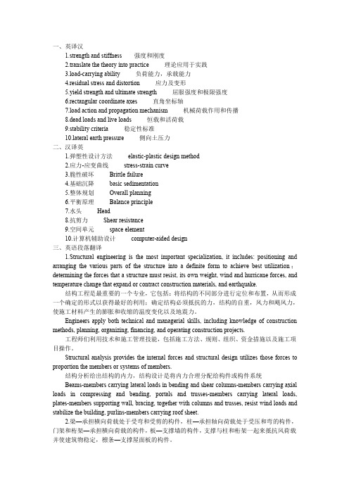
第7卷第2期2008年4月 江南大学学报(自然科学版)Journa l of J i a ngnan Un i versity(Na tura l Sc i ence Ed iti on) Vol .7 No .2Ap r . 2008 文章编号:1671-7147(2008)02-0211-05 收稿日期:2007-02-04; 修订日期:2007-04-03. 基金项目:湖北省交通科技项目(鄂交技[2000]320号). 作者简介:黄平明(1965-),男,湖北当阳人,教授,博士生导师.主要从事公路桥梁养护维修及加固技术、大跨径桥梁施工控制及桥梁评定技术等研究.E mail:hpm ing@vi p.sina .com基于健康观测的大跨度悬索桥结构评估黄平明1, 刘旭政1, 张永健1,2(11长安大学公路桥梁与隧道陕西省重点试验室,陕西西安710064;21湖南省高速公路管理局,湖南长沙410001)摘 要:结合宜昌长江公路大桥的健康监控,探讨了悬索桥结构健康监控中的主要内容及实施方法.介绍了几种常见的桥梁结构评估方法,并对宜昌长江公路大桥进行结构评估,为同类桥型的健康监测及结构评估提供有益参考.关键词:桥梁工程;悬索桥;健康监测;结构评估中图分类号:U 446.2文献标识码:AHea lth M on itor i n g and Structure A ssessm en t of theY i chang Yangtze R i ver H i ghway Br i dgeHUANG Ping 2m ing 1, L IU Xu 2zheng 1, ZHANG Yong 2jian1,2(Key Laborat ory f or H igh way B ridge and Tunnel of Shaanxi Pr ovince ,Chang ’an University ,Xi ’an 710064,China;Hunan Bureau of Exp ress way Ad m inistrati on,Changsha 410001,China )Abstract:Combining with the Yichang Yangtze R iver high way bridge,the p rinci pal content and the execute way of health monit oring f or the sus pensi on bridges are p resented .The general methods of bridge structure assess ment are intr oduced,and the structure assess ment of the Yichang Yangtze R iver highway bridge is co mp leted .The results can p r ovide good reference t o the sa me type bridges in health monit oring and structure assess ment .Key words:bridge engineering;sus pended bridge;health monit oring;structure assess ment 桥梁在建成通车后,由于受到气候、氧化、腐蚀或老化等环境因素的影响,并且在静载和活载的长期作用下,桥梁结构的强度和刚度会随着时间的增加而降低.这不仅会影响行车安全,更会缩短桥梁的使用寿命.特大型桥梁作为路线的咽喉,需要对桥梁的健康状况进行监测,确定桥梁的健康状况,并对结构进行状态评估,从而指导运营阶段的养护维修工作,及时发现安全隐患,保证桥梁的行车安全.大型桥梁的结构状态评估技术在国内外已经受到广泛的关注和重视,成为桥梁研究领域的热点问题[122].目前存在多种桥梁安全评估方法,主要理论集中在可靠度理论、层次分析法、模糊理论、神经网络及专家系统等[326].近年来,我国许多学者就桥梁结构的安全性评估进行了广泛而深入的研究,但大多数都集中在对中小型桥梁的结构评估或者桥梁局部构件的评估[728],对于大跨度桥梁的综合评估研究较少,而针对大跨度悬索桥结构评估的研究则更少. 宜昌长江公路大桥的主桥净跨为960m,全长1187.489m,桥面全宽30m,桥型采用双塔单跨钢箱梁悬索桥,是首座完全依靠我国技术建造的跨径达千米的悬索桥.大桥于2001年9月18日通车运营,运营后的一年内,每隔3个月对大桥进行一次健康观测,总共进行了4次.从观测结果看,大桥主缆标高、桥面标高、主要结构内力均有不同程度的变化,因此,建立长期稳定的健康观测体系以及对大桥的结构评估,是十分必要的.1 目标及内涵桥梁结构的健康观测有以下几个目标:1)确定桥梁的健康状况,辅助制定日常养护维修方案.通过健康观测搜集到的数据,分析结构的实际状况,比较分析结构的实际状况与结构理想状况的偏差,分析偏差产生的原因,为日常养护工作确定方向.2)保证大桥的运营安全以及预测大桥以后的健康状况.对比分析健康观测收集的数据,了解大桥目前的健康状况从而保证大桥的安全运营,同时分析数据流的趋势,预测结构可能出现的问题,提出解决方案,消灭结构的安全隐患;确保大桥结构的安全以及桥上行车、行人的安全.3)为大桥的评估工作提供前提保障.结构的健康观测是大桥结构评估的前提,健康观测包含了评估工作的部分内容,并且可以促进评估工作的进行.例如,结构的可靠性评估方法、结构损伤或缺陷及其诊断和检损技术、桥梁评估工作的标准化和规范化、大桥修复加固技术,以及大桥的养护维修策略和监测系统的信息管理技术等.桥梁健康检测的基本内涵是通过对桥梁结构状态的监控与评估,为工程在特殊气候、交通条件下或运营状况严重异常时发出预警信号,为桥梁维护、维修与管理决策提供依据和指导.为此,监测系统通常对以下几个方面进行监控:1)桥梁结构在正常环境与交通条件下运营的物理与力学状态;2)桥梁重要非结构构件和附属设施的工作状态;3)桥梁结构构件耐久性;4)桥址处的环境条件等.2 主要监测内容2.1 几何位置观测2.1.1 主缆线形观测 主缆是悬索桥的主要承重结构,是整体结构安全的关键所在.主缆线型的变化随外界环境(如温度场、荷载等)的改变会发生较大的变化,准确的测定主缆线型,是全桥几何观测的主要内容之一.主缆的几何位置测量选定每根主缆中跨L /4、中跨L /2、中跨3L /4、边跨跨中5个点,两根主缆共10个点(Z 1~Z 10)作为监测目标,每次健康观测测量这10个点的标高.在考虑温度场、索塔偏位等的影响后,与设计理想状态比较,得到偏差值.根据偏差值的大小确定主缆线型几何状态,并将测量值与先前测量值比较,找出主缆标高的变化规律,分析原因,确定主缆线型变化规律的合理性.主缆线型监测测点布置见图1,主跨跨中主缆标高健康观测数据见表1.图1 主缆线型监测测点布置F i g .1 M on itor i n g po i n ts for cable shape表1 中跨跨中主缆标高健康观测数据Tab .1 Cable eleva ti on da t a for m i ddle of m i d 2span测试断面数据采集时刻测试温度/℃上游标高/m 下游标高/m 标高均值/m理论标高(20℃)差 值中跨L /22003-06-18 20:5029.388.24388.25288.24788.1620.0852004-01-11 23:308.088.23688.24388.23988.1620.0772004-06-12 23:3029.588.22788.26988.24888.1620.0862005-01-28 23:305.288.24288.25288.24788.1620.085212 江南大学学报(自然科学版) 第7卷 2.1.2 主梁线形观测 在桥面上选定上下游侧主缆吊点附近的八分点(全桥共14个点)作为健康观测图的测量点(桥面线型观测测点布置见图2).健康观测时测量这些点位的标高.在考虑温度场、索塔偏位等的影响后,与设计理想状态做比较,得到偏差值.根据偏差值的大小确定桥面线型几何状态,并将测量值与先前测量值进行比较,找出桥面线型的变化规律,分析原因,确定桥面线型变化规律的合理性.图2 桥面线形监测测点布置F i g .2 M on itor i n g po i n ts for beam shape2.1.3 索塔位置及散索鞍位置观测 在南北两个索塔的上下游塔顶各选择一个固定的监测点(共4个点),该点必须与测量控制网中的某一测站点通视.通过对该点的测量,可以确定索塔的偏位情况,从而可以和理论理想状态比较,确定偏差值的大小及偏差的变化规律.散索鞍位置对于主缆线形及结构整体受力影响较大.大桥散索鞍位置观测采用在南北两岸的上下游索鞍上确定一个固定的监测点(共4个点),通过对该点的测量,确定索鞍的位置变化情况,从而可以和理论理想状态进行比较,确定偏差值的大小及偏差的变化规律.2.2 静力观测2.2.1 主跨锚跨张力测试 主缆对悬索桥的结构安全至关重要,而且不可更换.锚跨张力测试是在悬索桥的锚室(共4个)内采用动测法(测试振动频率)测试索股的张力.监测点设在4个锚室内,分别在每个锚室的上端、下端、左侧、右侧、中间索股进行主缆内力监测.北锚索力上游张力健康观测数据见表2.表2 北锚上游索力健康观测数据Tab .2 Cable ten si on da t a for north 2anchor of upstream测试索号第1次观测/k N(2003-06-1820:50)第2次观测/k N(2004-01-1123:30)第3次观测/k N(2004-06-1223:30)第4次观测/k N(2005-01-2823:30)21214.721200.921199.031182.6681271.741252.861240.321220.17521330.201325.421311.221301.64781365.201326.271309.561302.221041192.491201.681208.981220.172.2.2 吊索索力测试 吊索索力的监测主要用振动方法测量索的自振频率和振型,利用有关的索力公式推算斜拉索的拉力.每次健康观测时对全桥312个吊点、1248根吊索的索力进行全面测试,确定各个吊索的索力大小是否正常、受力是否均匀、有无异常变化,以此作为吊索索力状况的判断依据.2.2.3 索塔应力测试 对于悬索桥结构来说,主塔结构的内力分布和在各种载荷下的响应,为结构损伤识别、疲劳损伤寿命评估和结构状态评估提供依据.索塔应力的大小利用施工控制时预埋于索塔内的钢筋计,用寻检仪测试索塔内混凝土应变的大小,再通过理论计算得到索塔应力.2.3 振动监测桥梁动态性能的改变反映了桥梁的刚度性能的改变,因而获取桥梁的动力特性即获取了结构的“指纹”,作为评价桥梁健康状态的主要指标.结构的整体性能改变时,其模态参数(如频率、振型等)也会发生相应的变化.通过对悬索桥主缆和吊索、振动特性的监测,可以考察悬索桥缆索系统的疲劳响应,进而考察结构的安全可靠性.例如在其他条件不变的情况下,若发现大桥振桥频率降低,则表示大桥的整体刚度在退化;若大桥某阶振型的频率变化不大,但发现局部振型有变化,则表示大桥局部部位有缺陷或损坏而引起的局部刚度退化等.用环境随同振动方法测量大桥的振动特性,如自振频率、振型和阻尼值等.大桥结构振型包括以下几种:1)悬吊结构(加劲梁)的横向弯曲振型、竖向弯曲振型及扭转振型;2)桥塔的顺桥向弯曲振型、横桥向弯曲振型及扭转振型;3)索和吊杆的面内和面外弯曲振型.312 第2期黄平明等:基于健康观测的大跨度悬索桥结构评估2.4 温度监测通过对桥梁温度场分布状况的监测,可为桥梁设计中温度影响的计算分析提供原始依据.对不同温度状态下桥梁的工作状态变化,如桥梁变形、应力变化等进行比较和定量分析,对于桥梁设计理论的验证和完善均是有益的.利用多路温度测试系统(MCTI ),在全桥主要结构上布设温度测点.主缆上共10个测试断面(每根主缆选取中跨L /4、中跨L /2、中跨3L /4、边跨跨中5个点),40个测点(主缆每个测试断面上4个测点),具体布置见图3.索塔上8个测试断面(每个索塔分别设置中横梁及上横梁),32个测点(索塔每个测试断面上4个测点).钢箱梁设置2个测试断面,每个断面上4个测点.图3 主缆温度测点布置F i g .3 M on itor i n g po i n ts for ma i n cable te m pera ture3 结构健康状况评定桥梁结构评估的内容为承载能力、营运状态和耐久能力.承载能力评估与结构或构件的极限强度、稳定性有关.其评估的目的是要找出桥梁结构的实际安全储备,以避免桥梁在日常使用中发生灾难性的后果.因其与人身安全和财产损失有关而成为桥梁结构评估的主要内容.营运状态评估与桥梁结构或其构件在日常荷载工作下的变形、裂缝、振动等有关.在指定结构工作条件和定期养护维修的情况下,桥梁结构营运状态评估结果是十分重要的.耐久能力的评估侧重于桥梁损伤及其成因,以及对材料的物理特性的影响.目前存在多种桥梁安全性评估方法,所采用的理论主要集中在可靠度理论、层次分析法、模糊理论、神经网络以及专家系统等.宜昌长江公路大桥采用分部件的综合评定方法进行.根据JTG H11—2004《公路桥涵养护规范》,评定等级分为一类、二类、三类、四类、五类.综合评定采用计算方法如下:D r =100-∑ni =1R iWi/5式中:R i 为各部件确定的评定标度(0~5);W i 为各部件权重,∑Wi=100;D r 为全桥结构技术状况评分(0~100),评分高表示结构状况好,缺损少.评定分类采用界限:D r ≥88为一类;88>D r ≥60为二类;60>D r ≥40为三类;D r <40为四类、五类.根据宜昌大桥健康观测所测数据,采用上述方法计算出宜昌大桥技术状况得分为82分,属于二类桥梁,即桥梁总体状况较好,重要部件功能良好,承载能力和桥面行车条件达到设计标准.从评估结果来看,宜昌长江公路大桥运营3年多来,主缆锚跨各根索股受力均匀,实测受力与理论计算值相差较小;吊索索力没有明显的变化,满足结构安全系数的要求;主缆、吊索受力情况良好;几何线形与设计值偏差不大,这表明大桥健康状况良好.4 结语桥梁健康监测是在桥梁建设规模越来越大、在交通运输及社会生活中的作用越来越重要、计算机技术及通信技术迅速发展的背景下出现的一个新的技术领域.桥梁动力健康监测作为桥梁健康监测的重要组成部分之一,涉及结构分析、传感技术、测试技术、数据通信、信号处理、数据管理及状态评估等多个学科.关于大跨桥梁健康监测还有许多问题需要进行研究,尤其是在损伤识别、状态识别与安全性评估方面.这主要是由于:1)桥梁结构及其工作环境的复杂性和不确定性对结构模态响应的灵敏性造成了不利影响,导致了目前桥梁整体监测与评估的困难;2)根据大型结构的监测数据反演其结构健康状态和可能的结构损伤,是一个复杂结构体系在不完善条件下的反问题,结构的状态反演、损伤识别和状态评估尚有待深入研究;3)对大跨桥梁在使用年限内工作特性的变化412 江南大学学报(自然科学版) 第7卷 缺乏全面深入的研究,难以建立客观统一的桥梁结构状态评估标准.目前桥梁健康监测这一新技术还属于研究阶段,对桥梁动力健康监测的方法、理论还有待于进一步研究.文中对宜昌长江公路大桥健康监测过程中涉及的问题进行了探讨,并根据健康状况评定结果对于大桥的维护提出了日常维护方案,希望能对同类桥型健康监测系统的发展及实现规范化方面起到参考及促进作用.参考文献(References ):[1]袁万成.桥梁健康监测与状态评估的研究现状与发展[J ].同济大学学报:自然科学版,1999,27(2):1842188.Y UAN W an 2cheng .Current research and devel opment of structural health monit oring and conditi on assess ment f or bridges[J ].Journal of Tongji University:Natural Seience,1999,27(2):1842188.(in Chinese )[2]邬晓光,徐祖恩.大型桥梁健康监测动态及发展趋势[J ].长安大学学报:自然科学版,2003,23(1):39242.WU Xiao 2guang,XU Zu 2en .Devel opment of l ong 2s pan bridge health monit oring [J ].Journal of Chang ’an University:Natural Science Editi on,2003,23(1):39242.(in Chinese )[3]李爱群,缪长青,李兆霞,等.润扬长江大桥结构健康监测系统研究[J ].东南大学学报:自然科学版,2003,33(5):5442548.L IA i 2quan,M I A O Chang 2qing,L I Zhao 2xia,et .Health monit oring syste m f or the runyang yangtse river bridge [J ].Journal of S outheast University:Natural Science Editi on,2003,33(5):5442548.(in Chinese )[4]张启伟.桥梁健康监测中的损伤特征提取与异常诊断[J ].同济大学学报:自然科学版,2003,31(3):2582262.Z HANG Q i 2wei .Da mage feature extracti on and novelty detecti on f or bridge health monit oring[J ].Journal of Tongji University:Natural Science Editi on,2003,31(3):2582262.(in Chinese )[5]兰海,史家均.灰色关联分析与变权综合法在桥梁评估中的应用[J ].同济大学学报:自然科学版,2001,29(1):50254.LAN Hai,SH I J ia 2jun .Degree of grey incidence and variable weight synthesizing app lied in bridge assess ment[J ].Journal of T ongji University:Natural Science,2001,29(1):50254.(in Chinese )[6]刘沐宇,袁卫国.基于模糊神经网络的大跨度钢管混凝土拱桥安全性评价方法研究[J ].中国公路学报,2004,17(4):55258.L I U Mu 2yu,Y UAN W ei 2guo .Research on safety assess ment of l ong 2s pan concrete 2filled steel tube arch bridge based on fuzzy 2neural net w ork[J ].China Journal of H igh way and Trans port,2004,17(4):55258.(in Chinese )[7]胡熊,吉祥,陈兆能,等.拉索桥梁安全性与耐久性评估的专家系统设计[J ].应用力学学报,1998,15(4):1222126.HU Xi ong,J I Xiang,CHE N Zhao 2neng,et al .An expert syste m design of the security and durability assess ment for stayed cable bridge[J ].Chinese Journal of App lied M echanics,1998,15(4):1222126.(in Chinese )[8]吕颖钊,贺栓海.缺损钢筋混凝土梁桥模糊可靠性评价模型[J ].交通运输工程学报,2005,5(4):58262.LV Ying 2zhao,HE Shuang 2hai .Fuzzy reliability evaluati on of defective RC bea m bridge [J ].Journal of Traffic and Trans portati on Engeerning,2005,5(4):58262.(in Chinese )(责任编辑:杨 勇)512 第2期黄平明等:基于健康观测的大跨度悬索桥结构评估。


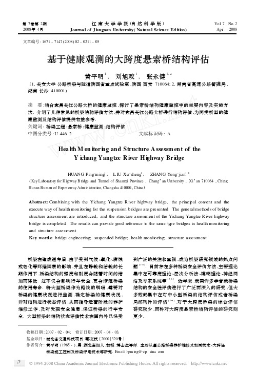
*Corresponding author.E-mail:admin @sohansen.dk.Journal of Wind Engineeringand Industrial Aerodynamics 74—76(1998)839—847Coupled buffeting response of suspension bridgesL.T.Thorbek,S.O.Hansen *S v end Ole Hansen ApS,Sct.J ~rgens Alle &5-7,DK-1615Copenhagen V.,DenmarkAbstractThe theoretical formulation of coupled buffeting response of suspension bridges is outlined.The influence of coupling between vertical and torsional modes on the calculated buffeting response is the main focus of this paper.The paper gives a mathematical formulation of the problem,and for a streamlined bridge girder deck section,the influence of mode coupling is illustrated.Guidelines regarding the need of including mode coupling in the calculations are given as a function of the critical flutter wind velocity of the suspension bridge in ques-tion. 1998Elsevier Science Ltd.All rights reserved.Keywords:Buffeting response;Modal load;Mode coupling;Motion-induced wind load;Classi-cal flutter and suspension bridges1.IntroductionThe large flexibility of suspension bridges indicates that bridge movements are of primary interest,i.e.deflections,accelerations,etc.The induced stresses in the struc-ture should also be considered carefully during the design.The total wind load on a bridge deck,F ,can be calculated as a sum of three wind load components:The time-averaged mean wind load,F O ,the fluctuating wind load due to air turbulence (buffeting),F ,and the motion-induced wind load,F .Response from the time-averaged mean wind load,which may be determined using standard procedures for static loads,is not included in the paper.Response from buffeting wind load and motion-induced wind load are of primary interest here.0167-6105/98/$19.00 1998Elsevier Science Ltd.All rights reserved.PII:S 0167-6105(98)00076-22.Theoretical formulation of buffeting responseThe theoretical formulation presented here is based on modal loads.The natural vibrations in still air of the vertical and torsional modes considered are assumed to be mutually independent and are described by(y,t)" (y)p(t),(1) (y,t)" (y)q(t),(2) where (y)and (y)are the vertical and torsional mode shapes in still air.At the critical flutter wind velocity,coupling between the two modes in question leads to the destructive phenomenon normally called classicalflutter.The structural parameters such as the mass and mass moment of inertia should be included in the calculations as modal mass and modal mass moment of inertia.The equivalent mass,m ,is defined by the modal mass of the entire structure normalized with the square of the mode shape integrated over the bridge deck length,i.e.m C"1 m(y) (y)d y/" (y)d y,(3)where y is a coordinate along the entire structure and S and D indicate that the integration should be made over the structure and deck,respectively.During erection of suspension bridges there is a large difference between the actual mass of the deck plus main cables and the equivalent mass of the structure.This is due to large vibrations of the main cables over the part of the structure where no deck has been erected yet;see Ref.[1]for further explanations.It is,therefore,important to include the mass of the entire structure in the analyses.The equivalent mass moment of inertia,I ,is defined in a similar manner,i.e.I "1 I(y) (y)d y/" (y)d y.(4)The tendency for two modes to couple depends on their mode shapes and the natural frequencies in still air.Typically,a vertical deflection mode couples with an angular rotation mode when the two modes are of similar shape and when the natural frequency in still air of the torsional mode is higher than that of the vertical mode.The last requirement for mode coupling is essential.Whether two modes will couple can be expressed by mode coupling coefficients,C K and C?,given byC K"" (y) (y)d y/" (y)d y,(5)C?"" (y) (y)d y/" (y)d y.(6)840L.T.Thorbek,S.O.Hansen/J.Wind Eng.Ind.Aerodyn.74—76(1998)839–847L.T.Thorbek,S.O.Hansen/J.Wind Eng.Ind.Aerodyn.74—76(1998)839–847841 Mode coupling depends on the product C K C?.When the vertical and torsional mode shape of the deck are identical,C K C?"1,indicating that mode coupling is likely.If the product is close to zero,mode coupling is not likely.As an example, coupling between symmetrical and asymmetrical mode shapes is not possible. Simplifying the bridge to a system with two degrees of freedom gives the following differential equations for the vertical and torsional motion:" (y)d y,(7) m (p(#2 K K p# K p)"F* #F* /" (y)d y,(8)I (q(#2 ? ?q# ?q)"F+ #F+ /where K,and ?are structural damping ratios to critical in still air,and K,and ? are the natural angular frequencies in still air,i.e.2 multiplied by the natural frequencies in Hz.F* and F+ are modal loads due to air turbulence defined by1 F*R(y,t) (y)d y,(9)F* (t)"1 F+R(y,t) (y)d y,(10)F+ (t)"where F*R(y,t)and F+R(y,t)are the turbulence induced wind loads,see Eq.(21). F* and F+ are the motion-induced modal wind loads,which are described in the next section.3.Motions-induced wind load on bridge decksCoupling between a vertical and a torsional mode shape occurs for many suspen-sion bridges.The mathematical model used for the motion-induced wind loads was originally formulated in the aeronauticalfield of application.R.H.Scanlan trans-ported the formulation into the bridge community,and it has been described in several papers and textbooks;see e.g.Refs.[2,3].As for most structures subjected to wind load,the motion-induced wind load is proportional to the velocity pressure,q" º .Furthermore,the motion-induced wind load depends on the vertical deflection, ,angular rotation, ,and vertical and angular velocities, and ,respectively.The dependence is given by the so-called aerodynamic derivatives;see Eqs.(11)and(12)below.Assuming harmonic motion at a frequency n,and mode shapes given by Eqs.(1) and(2),the motion-induced modal wind load in the vertical and torsional modesconsidered,F * and F +,respectively,are given by,see Ref.[1],F * "º b ,KH* (K )p º#KC K H* (K )bq º#K C K H* (K )q #K H* (K )p b ,(11)F + "º b , KC ?A* (K )p º#KA* (K )bq º#K A* (K )q #K C ?A* (K )p b ,(12)where the reduced non-dimensional frequency K is defined asK " b º"2 nb º,(13)b is the bridge deck width,ºis the wind velocity, is the angular frequency of the oscillation,and n is the frequency in Hz.The non-dimensional coefficients H *G and A *G ,i "1,2,3,4,are called aerodynamic derivatives.These should be measured in a wind tunnel using a vibrating section model,see Ref.[4],or based on numerical flow calculations.During recent years the latter procedure has turned out to give reliable results,see e.g.Ref.[5].It is worth noting that the notation used here gives aerodynamic derivatives twice the magnitude of the aerodynamic derivatives defined in Ref.[2].Furthermore,H * ,H * ,A * and A * have opposite signs due to the present sign convention,in which the lift force and vertical deflection are both positive upwards.The notation used here is identical to the one used in Ref.[1].If the buffeting response is calculated using a simple approach all cross terms of the aerodynamic derivatives (H * ,H * ,A * ,A * )are assumed negligible in the buffeting calculation.This paper focuses on the importance of these cross terms.Neglecting the cross terms simplifies the problem considerably,but for wind velocities close to the critical flutter wind velocity,the cross terms are important for the buffeting response and should,therefore,not be neglected.The time-consuming part of the work is to implement the theory outlined in this paper in a computer program.Having done this,calculating buffeting response for different cross sections and bridges is a simple task,since the only input data is the mass,mass moment of inertia,aerodynamic derivatives,mode shapes and natural frequencies in still air.The buffeting response calculation presented takes into account that mean wind velocities and turbulence characteristics may vary along the bridge deck,e.g.due to topographical effect.This is of interest for many cable-supported bridges.4.Spectral representation of buffeting vibrationsThe coupled buffeting vibrations are calculated by spectral analysis and it follows the formulation given by Ref.[1].Transferring the motion-induced wind load terms in842L.T.Thorbek,S.O.Hansen /J.Wind Eng.Ind.Aerodyn.74—76(1998)839–847the differential equations (7)and (8)to the left-hand side and taking the Fourier transform on both sides gives the following well-known matrix equation for a system with two degrees of freedom (upper index T refers to transposed and complex conjugated):S NN S NO S ON S OO "A \ S **S *+S +*S ++(A \ )2,(14)where spectra and cross-spectra of p and q ,defined in Eqs.(1)and (2),are the matrixelements on the left-hand side,spectra and cross-spectra of F * and F + ,defined by Eqs.(9)and (10),are the elements of the second matrix on the right-hand side,andthe stiffness matrix A is given by A "a m C K " (y )d y a m C Kb " (y )d y a I C K 1b " (y )d y a I C K " (y )d y .(15)The elements a HI are given by a "! #2i K #1! 2 (H* #iH* ),(16)a "! 2 C K (H * #iH * ),(17)a "! 2 'C ?(A* #iA* ),(18)a "! #2i ? S # S ! 2 '(A* #iA* ),(19)where " K , S " ?K, K "m , '"I .(20)The buffeting wind load,F *R and F +R ,per unit of deck length are given by,see Ref.[1],F *R F +R "12 º b 2C *dC *d #C "h b 2C +b dC +d b u ºw º (21)where C ",C *and C +are the static force coefficients,h is the height of the bridge deck used as reference for the drag force coefficient C ",and u and w are the along-wind and vertical turbulence component,respectively.L.T.Thorbek,S.O.Hansen /J.Wind Eng.Ind.Aerodyn.74—76(1998)839–847843Normally,the most important coefficients in Eq.(21)are the derivatives of the lift coefficient and moment coefficient used in combination with the vertical turbulence component,w .The spectra of the modal loading components associated with the modal displacements functions,see Eqs.(9)and (10),are given by,see Ref.[1], S **(n )S ++(n )S *+(n ) "( º bl ) , (2C *) "J S **(n )" d C *d #C "h b "J U **(n )" (2C +b ) "J S ++(n )" (d C +d b ) "J U ++(n )" 4C *C +b "J S *+(n )" d C *d #C "h b d C +d b "J U *+(n )" S S (n )S U (n ),(22)where l is the bridge deck length,and the joint acceptance function,"J H 67(n )" ,for modal loading components are (X ,½"¸,M ;j "u ,w )"J H 67(n )" "" H 67(n )" 1l J J g H 6(y )g H 7(y ) H (r W ,n )d y d y ,(23)where r W is the distance between the two loading components considered,and the g -functions are defined in Eqs.(24)—(27)below.The cross-sectional aerodynamicadmittance function," H 67(n )" ,takes into account the load correlation across the bridge deck.For normally used streamlined cross sections the Sears function is a good approximation to the cross-sectional aerodynamic admittance function.H is the normalized co-spectrum or root-coherence function.This function takes the correlation of the wind load along the bridge deck into account.Several wind-tunnel tests and full-scale experiments have shown that the correlation of aerodynam-ic forces is stronger than that of the turbulence fluctuations in the incoming air flow.For streamlined box-girder bridge sections some data are given by Ref.[6].The double integral in Eq.(23)may be calculated by to single integrals as shown in Ref.[1].This reduces the computer time necessary to a minimum.The g -functions take the variation of mode shapes and wind load along the bridge into account.The wind load may vary due to topographical effects.g (y )are defined byg S *(y )" (y ) C *(y )C * º(y )º S U (y ,n )S U(n ),(24)g U *(y )" (y ) d C *(y )/d #C "(y )h /b (d C */d #C "h /b )PCD º(y )º S S (y ,n )S S(n ),(25)g S +(y )" (y ) C +(y )C + º(y )ºS S (y ,n )S S (n ),(26)844L.T.Thorbek,S.O.Hansen /J.Wind Eng.Ind.Aerodyn.74—76(1998)839–847Fig.1.Response spectra at three different mean wind velocities.Mode coupling is included in all spectra shown.g U +(y )" (y ) d C +(y )/d d C + /d º(y )º S U (y ,n )S U (n ).(27)The index ref indicates that the value should be calculated at a reference point chosen.The choice of reference point does not influence the calculations,but the reference value chosen should offcourse be different from zero.As mentioned before the two g -functions including the vertical turbulence component and the derivatives of the force coefficients are usually the most important when calculating the buffeting response of suspension bridges.5.ExampleThe influence of mode coupling is illustrated by the buffeting behavior of a suspen-sion bridge with a streamlined box-girder deck section.The wind direction is perpendicular to the bridge axis.The aerodynamic derivatives are close to the derivatives valid for a flat plate.The vertical wind spectrum is in accordance with Ref.[2],and the normalized co-spectrum of vertical turbulence components with lateral separations follows a traditional exponential expression with a correlation decay constant of 8.The critical flutter wind velocity of the bridge considered is approximately 90m/s.In Fig.1the spectrum of the vertical deflection and torsional rotation are shown.The spectra are normalized with the wind velocity,º,raised to the power of 4.Thereby the dependence of the velocity pressure,q " º ,is removed,meaning that if the response did only depend on the velocity pressure,the spectra shown would be alike.Motion-induced wind load are seen to change this pattern considerably when the wind velocity is close to the critical flutter wind velocity.L.T.Thorbek,S.O.Hansen /J.Wind Eng.Ind.Aerodyn.74—76(1998)839–847845Fig.2.Bridge buffeting response as a function of mean wind velocity.Mode coupling is included in the solid lines,not in the dotted lines.At low wind velocities the vertical spectrum only consist of a single peak at the vertical natural frequency.This frequency does not depend significantly on the wind velocity.At increasing wind velocities a peak at the torsional natural frequency can be seen.This is due to the coupling between the two modes.The spectra show that the torsional frequency decreases as the wind velocity increases.The vertical and torsional frequency comes closer together,and becomes identical at the critical flutter wind velocity.Fig.2shows the total response as a function of the wind velocity.The solid lines include mode coupling,and the dotted lines are without mode coupling.Mode coupling for the suspension bridge in question becomes important for mean wind velocities larger than approx.60%of the critical flutter wind velocity.The response increases rapidly for wind velocities close to the critical flutter wind velocity.The no mode-coupling situation is obtained by assuming the off-diagonal terms of the A -matrix in Eq.(15)equal to 0.The shaded area indicates the wind velocities where the bridge has become unstable due to flutter.The dotted lines could have been continued into this area,because the uncoupled situation is unaffected by flutter instability,but for real-life conditions this gives no meaning.The large vibrations occurring at wind velocities close to the critical flutter wind velocity will depend on the geometrical non-linearities of the cable-supported struc-ture.This second-order effect is not included in the present formulation.6.ConclusionFor suspension bridges with streamlined bridge deck sections,and with ratios of 2—3between the torsional and vertical natural frequencies in still air,mode coupling846L.T.Thorbek,S.O.Hansen /J.Wind Eng.Ind.Aerodyn.74—76(1998)839–847L.T.Thorbek,S.O.Hansen/J.Wind Eng.Ind.Aerodyn.74—76(1998)839–847847 should be taken into account in response calculations at mean wind velocities exceeding approximately60%of the criticalflutter wind velocity.The spectral procedure described in the paper is straightforward to implement on a personal computer and the computer time necessary to do the calculations is modest as long as the joint acceptance function is calculated by two single integrals,see Ref.[1].Calculating the joint acceptance function as double integrals will increase the necessary computer time considerably.References[1]C.Dyrbye,S.O.Hansen,Wind Loads on Structures,Wiley,New York,1996.[2]R.H.Scanlan,E.Simiu,Wind Effects on structures,An Introduction to Wind Engineering,2nd Ed.,Wiley,New York,1986.[3]R.H.Scanlan,Wind dynamics of long-span bridges,in:rsen(Ed.),Aerodynamics of LargeBridges,Balkema,Rotterdam,1992,pp.47—57.[4]E.Hjorth-Hansen,Section model tests,in:rsen(Ed.),Aerodynamics of Large Bridges,Balkema,Rotterdam,1992,pp.95—112.[5]J.H.Walther,Discrete vortex method for two-dimensionalflow past bodies of arbitrary shapeundergoing prescribed rotary and translational motion,Ph.D.Thesis.Department of Fluid Mechanics, Danish Technical University,1994.[6]A.G.Davenport,J.P.C.King,rose,Taut strip model tests,in:rsen(Ed.),Aerodynamics ofLarge Bridges,Balkema,Rotterdam,1992,pp.113—124.。
Advanced Structural Analysis Structural analysis is a crucial aspect of engineering that involves determining the behavior of structures under different loads and ensuring their safety and stability. It plays a vital role in the design and construction of buildings, bridges, dams, and other infrastructure projects. As an AI, I understand the importance of advanced structural analysis in ensuring thestructural integrity of various constructions. One of the key perspectives to consider in advanced structural analysis is the use of advanced computationaltools and software. These tools allow engineers to model complex structures, simulate different loading conditions, and analyze the behavior of the structurein a virtual environment. By using these tools, engineers can optimize the design, identify potential weaknesses, and make informed decisions to improve the overall performance and safety of the structure. Another important perspective toconsider is the role of material properties in structural analysis. Different materials have different properties, such as strength, stiffness, and ductility, which can significantly impact the behavior of a structure under load. By understanding the material properties and how they interact with the structural elements, engineers can make informed decisions about the design, construction,and maintenance of the structure. Furthermore, advanced structural analysis also involves considering the dynamic behavior of structures. Structures are subjected to various dynamic loads, such as wind, earthquakes, and vibrations, which can affect their stability and safety. By analyzing the dynamic behavior of structures, engineers can design structures that can withstand these dynamic loads and ensure the safety of occupants and the longevity of the structure. Moreover, advanced structural analysis also involves considering the sustainability and environmental impact of structures. Sustainable design practices aim to minimize the use of resources, reduce waste, and lower the overall environmental impact of structures. By incorporating sustainability principles into structural analysis, engineers can design structures that are not only safe and stable but also environmentally friendly and cost-effective in the long run. In addition, advanced structural analysis also plays a crucial role in ensuring the safety and resilience of structures in the face of natural disasters. By analyzing the behavior ofstructures under extreme loading conditions, such as earthquakes, hurricanes, and floods, engineers can design structures that can withstand these events andprotect the lives and property of people. This aspect of structural analysis is particularly important in regions prone to natural disasters, where the safety and resilience of structures are paramount. Overall, advanced structural analysis isa multifaceted discipline that involves the use of advanced computational tools, consideration of material properties, analysis of dynamic behavior, incorporation of sustainability principles, and ensuring the safety and resilience of structures. By taking into account these perspectives, engineers can design structures thatare not only safe and stable but also sustainable, environmentally friendly, and resilient in the face of natural disasters. As an AI, I recognize the importanceof advanced structural analysis in ensuring the safety and longevity of various constructions and the well-being of society as a whole.。