动平衡计算中影响系数的通解算法及其应用
- 格式:doc
- 大小:25.50 KB
- 文档页数:4
9.1 动平衡机理概述众所周知,不平衡是旋转机械最常见的振动原因,并且其它一些故障,如不对中和碰摩等,也可以通过改善机组的平衡状态而予以减轻或消除,因此现场找平衡就成为消除机组振动的重要措施之一。
由振动理论知,振动的振幅不仅正比于静不平衡的离心力Meω2,而且还与动力放大因子R有关。
动力放大因子R是转子转速的单值函数,转速确定后,R 的值也将确定。
滞后角φ表明振动的幅值滞后于不平衡激励力Meω2的角度,并且随转速的改变而改变,当转速确定后,滞后角也为定值。
因此,只要系统符合线性假设,即物性参数(如支撑刚度,阻尼等)和特性参数(如固有频率和阻尼率等)不因振动大小而发生改变,则相同转速下轴承的振动正比于转子不平衡质量的大小,并且振动滞后于不平衡离心力的相位也为定值,这就是转子平衡的理论基础。
平衡是通过检测和调整转子的质量分布,即在转子的适当位置上加上或减去一定大小的质量(称为校正质量或配重),来减小转子的惯性主轴与旋转轴线的偏离,使机组的振动降到允许范围内。
平衡的作用是减少转子的挠曲,减低机组的振动并减少轴承及基础的动反力,保证机组安全,平稳,可靠地运行。
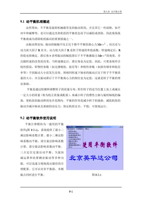
9.2 动平衡软件使用说明平衡计算模块为一通用的平衡软件(图9.2-1),系统提供了最小二乘法影响系数计算、最小二乘法影响系数动平衡、谐分量法影响系数计算、谐分量法影响系数动平衡、三点定位定量法动平衡、矢量加减运算和估算剩余振动等多种功能,可以迅速方便地找出最佳的合理配重。
它可以对多平衡面、多测振点同时进行平衡。
图9.2-1影响系数法只有当知道影响系数后才能使用,由于各机组实际情况不同,各机组的影响系数也大不相同。
它一般由技术人员根据经验得到的或通过多次试重得到。
最小二乘法影响系数计算模块通过试重可以自动计算出机组的最小二乘法影响系数。
进入最小二乘法影响系数计算模块后,选择对应的加重面和测振点(图9.2-2)后进入图9.2-3所示的对话框。
用户必须输入各测振点原始振动的振幅和相位(由于本软件为通用软件,故用户可以从前面的信号分析中得到一倍频振幅和相位,并人工输入)、试重后振动的振幅和相位以及试加重量的大小和角度,然后击一下计算按钮,即可得到计算结果,即该加重面对各测振点的最小二乘法影响系数。
动平衡分析设备动平衡不良或故障通常是指旋转机械的转子部件质量相对于旋转轴的轴心发生偏心时所引起异常振动。
动平衡异常对设备产生的不良影响1. 降低设备的预期使用寿命,特别表现在轴承的早期损坏;2. 缩短设备的保养周期;3. 增加设备维护成本;4. 影响产品质量;5. 恶化工作环境等。
以下公式可用来计算振动对球轴承理论寿命的影响:H={C/(L+2.6674*10~6MVF)}*(16667/RPM)其中:H = 球轴承寿命(小时)C = 轴承静负载(牛顿)L = 轴承工作负载(牛顿)M = 相对振动部件的重量(千克力)V = 测量的振动值(毫米/秒) F = 振动发生的频率(转/分钟)例如:轴承静负载=5,000牛轴承额定负载=100,000 牛测量部件重=6,000 千克力运行转速=1,800计算结果:动平衡不良所表现的特征及分析时的一些注意事项既然动平衡不良对设备有如此严重的影响,在设备存在动平衡不良时,我们就必须对其进行动平衡矫正,但在动平衡矫正前,分析鉴别引起动平衡不良原因是我们进行动平衡矫正的最本质的首要步骤,以下从不平衡的振动特征和一些已经验证过的分析技巧来论述如何鉴别不平衡:1. 不平衡的振动特征:不平衡的基本特征直观易懂,当质量分布不均的转子转动时,不平衡量的旋转特性即通过振动特征反映出来;a.振动的周期性与工作转速同频,主要振动能量集中于设备的一倍旋转速度;b.振动强度程度相对工作转速的变化很敏感;c.径向振动幅度最高;d.振动的振幅和相位角具有稳定性和可重复性;e.振动的相位角在水平和垂直方向相差约900。
2. 不平衡的分析确认:a.频谱的一倍转速振幅大且谐波非常小;b.重大振幅中不夹带其他峰值;c.运用高解析度放大或用时间同步平均方法证实精确的一倍转速特征;d.一倍转速频率的振幅在水平和垂直方向没有巨大差异,除非在结构上存在不对称的钢性特征;e.轴向一倍频的振动强度小于径向f.每个转动周期产生一次对称波形,不存在削顶或顶端间断;g.相位分析中,同一轴承座水平与垂直相差约90 度;3. 导致设备不平衡的主要因素(可矫正)有:a.加工公差与安装公差不正确;b.制造误差(转动部件偏心等);c.材质不均(铸件存在空洞等);d.部件缺损(转动部件腐蚀或磨损等);e.存在热变形或机械变形等;f.转动部件弯曲;g.异物附着导致质量偏心;4. 不能通过动平衡矫正的其他因素:a.设备存在严重松动(包括轴承间隙变大);b.设备在运行速度附近激发共振;c.轴破裂;d.轴承损坏;e.传动部件磨损导致力矩不平衡;f.设备存在不对心;g.设备安装倾斜(如设备基础沉降,设备安装调整垫损坏等造成);小结:引起动平衡不良的因素错综复杂,因此我们在动平衡前必须认真分析导致设备振动异常的真正原因,如果设备存在以上不可矫正原因,我们就必须在动平衡前将这些问题处理好,否则动平衡矫正将不能达到预期效果,在使用旭鼎仪器的MDF-320平衡机前也必须如此。
动平衡试加重响应经验公式
动平衡试加重响应经验公式是一种在旋转机械中用于评估不平衡状况的方法。
以下是对该公式的详细解释:
动平衡试验是一种用于检测旋转机械不平衡的方法,可以通过在机械上添加重物来进行调整。
试加重是动平衡试验的一个阶段,它采用经验公式来计算机械的不平衡程度。
试加重响应经验公式是计算机械不平衡量的公式。
它是通过测量机械在旋转时产生的振动来计算机械不平衡量的。
这个公式基于机械的运动状态,可以用于计算单面不平衡和双面不平衡。
该公式的基本形式为:
Ue = m ×e ×r
其中,Ue表示机械的试加重响应,m表示试加重质量,e表示不平衡量,r表示旋转半径。
需要注意的是,这个公式只适用于旋转轴向上的振动。
因此,在进行动平衡试验时,需要保证试验条件符合公式的要求,以保证测量结果的准确性。
总之,动平衡试加重响应经验公式是一种用于评估旋转机械不平衡状况的方法,能够用简单的公式计算机械的不平衡量,从而对机械进行必要的调整。
动平衡理论与方法动平衡理论与方法是一种研究动力学系统稳定性的方法。
它是化学动力学理论的重要组成部分,用于分析化学反应速率与反应物浓度之间的关系,并预测反应过程中的平衡状态。
通过动平衡理论和方法,我们可以对化学反应的平衡位置、反应速率以及当发生扰动时,系统如何重新达到平衡状态进行深入了解。
本文将介绍动平衡理论和方法的基本原理以及它们的应用。
一、动平衡理论的基本原理动力学是研究物质在反应过程中随时间变化的学科,它研究化学反应的速率以及速率方程。
反应速率可以表示为反应物浓度的函数,它与反应物的浓度有关。
平衡是指化学反应系统达到稳定状态,并且反应物与生成物的浓度不再发生变化。
动平衡理论是研究反应速率与反应物浓度之间的关系,以及反应系统达到平衡状态的理论。
1.科学家阿兰·图林于1863年提出了平衡反应速率相等的原则,即反应速率的正负相等,反应物与生成物浓度的变化相等。
2.动平衡理论基于动力学定律,这是描述化学反应速率与反应物浓度之间关系的定律。
根据反应物浓度对反应速率的影响,可以得到反应速率方程,进而用数学模型描述反应过程。
3.反应速率方程是一个描述反应速率与反应物浓度之间关系的函数方程。
它可以通过实验测定得到,然后用于预测反应速率及平衡浓度。
4.动平衡理论还涉及到活化能的概念。
活化能是指反应需要克服的能量障碍,它与反应速率密切相关。
通过测量反应速率在不同温度下的变化,可以求得反应的活化能。
二、动平衡方法的应用动平衡方法主要应用于以下几个方面:1.预测反应速率:通过测定反应速率方程中的速率常数及反应物浓度,可以预测反应速率。
根据速率方程,当反应物浓度发生变化时,可以计算出新的反应速率。
2.判断反应的平衡位置:通过动平衡理论,可以推导出反应物浓度与时间的函数关系,从而确定平衡位置。
当反应达到平衡时,反应物浓度与时间的变化图形呈现一个水平线。
3.预测反应过程中的平衡浓度:通过测定反应速率方程中的速率常数及反应物浓度,可以预测反应过程中的平衡浓度。
动平衡计算中影响系数的通解算法及其应用动平衡的质量,在动平衡计算方法上已作了大量的工作。
自1964年Goodman将最小二乘法引入柔性转子的动平衡计算中后,影响系数算法一直是动平衡试验中最常用的方法。
虽然这种方法有其固有的缺陷,但考虑的平衡面数、平衡转速数、“测点”数较多时具有一定的误差补偿能力。
按传统的影响系数算法,为求出各面的影响系数,需在每个加重面上分别单独加重,从而求得各面的单面影响系数。
但是在现场的动平衡试验中,常常是多平面同时加重,需要解决一些特殊条件下的影响系数的计算及提炼问题,即采用非常规的影响系数计算方法。
这些情形包括:(1)在熟知性能的机组上尝试一次加重或多面同时加重,当尝试的次数达到一定时,各加重平面的影响系数的分离计算。
(2)在多面同时加重时,若某些面的影响系数已知,加重次数足够时,未知面的影响系数的分离计算。
(3)包括试加重在内的加重次数超过了确定影响系数所必需的次数时,如何充分利用冗余的加重信息计算各面的影响系数。
对于以上的较为特殊的影响系数的计算问题,影响系数的分离计算在面数多于2个时,手工计算十分困难。
而加重次数冗余时影响系数的计算遵循何种准则,如何计算又是一个值得探讨的问题。
本文推导了涵盖以上3个方面特殊情形影响系数求解通式,它也适合于一般意义下的影响系数的求解。
1影响系数求解通式的推导设在某次动平衡试验中,有m个加重平面,n个“测点”,同一测点不同转速情况亦视为一新的“测点”。
对于多面同时试重的情形,须足够次的试(加)重后才能计算影响系数。
一般对于具有m个平面、n个“测点”的平衡计算问题,至少需m次的试重确定各面的影响系数值,并且每次试重并不要求只在一个面加重,允许每次在可加重的m个平面上任意加重。
为了使推导的公式适用于一般情形,假设在总共m个加重平面中,有k(k≤m)个加重面的影响系数未知。
另在试验中共有h次(试)加重,且加重次数满足h≥k。
在这种条件下,加重次数多于唯一确定未知影响系数所需的加重次数,即有冗余的加重信息,此时可利用冗余的信息对影响系数进行提炼,取代一般的矢量平均的办法,充分利用加重信息。
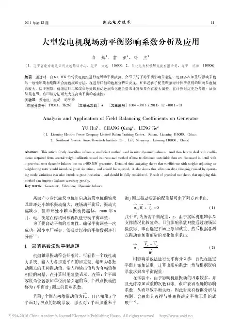
动平衡原理与应用动平衡原理与应用导言:动平衡原理是指在动力学中,任何物体的平衡状态都需要满足动态平衡的条件。
动平衡原理的应用广泛而重要,可以帮助人们理解和解决各种实际问题。
本文将从动平衡原理的概念和基本原理出发,逐步深入探讨其应用,并给出个人观点和理解。
一、动平衡原理的概念与基本原理1. 动平衡原理的概念动平衡原理是指物体在运动过程中保持平衡是通过力的合成等于零来实现的。
它与静力学平衡原理不同,静力学平衡是物体在静止状态下保持平衡的原理。
2. 动平衡原理的基本原理动平衡原理的基本原理包括牛顿第一定律和牛顿第二定律。
牛顿第一定律表明,物体在没有外力作用下要保持匀速直线运动或静止。
牛顿第二定律则告诉我们,物体的加速度与作用力成正比,与质量成反比。
根据这两个原理,可以推导出动平衡原理的数学表达式。
二、动平衡原理的应用1. 动平衡在工程中的应用动平衡在工程中有很多应用,其中最典型的应用是在旋转机械中。
例如,在汽车发动机、飞机发动机和电机等中,由于旋转部件造成不平衡,会引起振动和噪音。
通过动平衡技术可以减小或消除这些振动和噪音,提高机械设备的性能和可靠性。
2. 动平衡在航天领域的应用航天器在发射过程中往往需要经历高速旋转,如果不进行动平衡处理,就会导致严重的振动问题。
因此,动平衡在航天器的设计和制造中起到了至关重要的作用。
通过合理的动平衡技术,可以保证航天器在发射过程中的稳定性和安全性。
3. 动平衡在生活中的应用除了工程和航天领域,动平衡在日常生活中也有一些应用。
例如,电动车轮胎的动平衡调整,可以减小车辆的震动和提高车辆的行驶稳定性。
另外,在摄影领域,相机的镜头镜群也需要进行动平衡处理,以保证拍摄出的照片清晰度和稳定性。
三、总结与回顾动平衡原理是物体在动态平衡状态下保持平衡的原理,它与静力学平衡相对应。
其基本原理包括牛顿第一定律和牛顿第二定律。
动平衡的应用广泛,涵盖了工程、航天和生活等领域。
在工程中,动平衡可以减小机械设备的振动和噪音,提高性能和可靠性;在航天领域,动平衡可以确保航天器的稳定性和安全性;在生活中,动平衡可以提高车辆行驶的稳定性和照片的拍摄质量。
实用文档
影响系数法
影响系数法步骤
所谓的现场动平衡使用的方法,比较常用的就是影响系数法。
1、首先测转频的振幅和相位。
2、测量该设备时要知道该设备为刚性还是柔性转子,是有区别的,工作转速是
在临界转速前运行还是在临界转速后运行,加试重的方法是不一样的,具体情况具体分析。
3、通过振幅的大小及相位的位置,在该位置加试重(也就是欠量),试重的一般
追寻以下公式:WP=0.15MS÷R(N/3000)2
WP为实验质量(g)
M为转子的质量(kg)
R为加试重的半径(mm)
S为原始振动幅值(um)
N为平衡转速(r/min)
通过计算得出大约需试配重的重量。
4、测取加试重后的振幅和相位。
5、计算出设备应加重量和位置。
当转子的长度大于半径时,可能要通过双面平衡才能达到满意的效果。
1、双面的动平衡需要选两个加重平面及两个测振点。
2、测量两个测点的初始振动,在两个面同时加试重,得出两面的振动和相位。
也可单面逐个试加配重,视情况灵活运用。
测出振动的幅值和相位。
3、计算出需要加双面的重量和相位。
现场动平衡大约需要1—2次的配重,一般就可比较满意。
也有特殊情况,3次基本解决。
动平衡计算中影响系数的通解算法及其应用动平衡的质量,在动平衡计算方法上已作了大量的工作。
自1964年Goodman将最小二乘法引入柔性转子的动平衡计算中后,影响系数算法一直是动平衡试验中最常用的方法。
虽然这种方法有其固有的缺陷,但考虑的平衡面数、平衡转速数、“测点”数较多时具有一定的误差补偿能力。
按传统的影响系数算法,为求出各面的影响系数,需在每个加重面上分别单独加重,从而求得各面的单面影响系数。
但是在现场的动平衡试验中,常常是多平面同时加重,需要解决一些特殊条件下的影响系数的计算及提炼问题,即采用非常规的影响系数计算方法。
这些情形包括:(1)在熟知性能的机组上尝试一次加重或多面同时加重,当尝试的次数达到一定时,各加重平面的影响系数的分离计算。
(2)在多面同时加重时,若某些面的影响系数已知,加重次数足够时,未知面的影响系数的分离计算。
(3)包括试加重在内的加重次数超过了确定影响系数所必需的次数时,如何充分利用冗余的加重信息计算各面的影响系数。
对于以上的较为特殊的影响系数的计算问题,影响系数的分离计算在面数多于2个时,手工计算十分困难。
而加重次数冗余时影响系数的计算遵循何种准则,如何计算又是一个值得探讨的问题。
本文推导了涵盖以上3个方面特殊情形影响系数求解通式,它也适合于一般意义下的影响系数的求解。
1影响系数求解通式的推导设在某次动平衡试验中,有m个加重平面,n个“测点”,同一测点不同转速情况亦视为一新的“测点”。
对于多面同时试重的情形,须足够次的试(加)重后才能计算影响系数。
一般对于具有m个平面、n个“测点”的平衡计算问题,至少需m次的试重确定各面的影响系数值,并且每次试重并不要求只在一个面加重,允许每次在可加重的m个平面上任意加重。
为了使推导的公式适用于一般情形,假设在总共m个加重平面中,有k(k≤m)个加重面的影响系数未知。
另在试验中共有h次(试)加重,且加重次数满足h≥k。
在这种条件下,加重次数多于唯一确定未知影响系数所需的加重次数,即有冗余的加重信息,此时可利用冗余的信息对影响系数进行提炼,取代一般的矢量平均的办法,充分利用加重信息。
Use of Conversion Equations of Influence Coefficientson Two-Plane BalancingJohn J.Yu 1Nicolas P ton 2(1.Baker Hughes,Atlanta,USA,john.yu@baker ;2.Baker Hughes,Nantes,France,nicolas.peton@baker hughes.com )éAbstract:Typical rotors such as those on steam turbine or generator are often supported by two bearings with twobalance planes at both ends.Vibrations are monitored by a pair of proximity probes at each bearing.There are two approaches to reduce 1X vibration due to unbalance at both ends via balancing with influence coefficient method.The first approach is to treat it as a multiple-plane balancing problem involving 2x2matrix of complex influence coefficients.The second approach is to treat it as two single-plane balance problems using static (in-phase)and couple (180degree out-of-phase)components,respectively.Conversion equations of influence coefficients between these two approaches have been found previously by the author.The corresponding spreadsheets that convert influence coefficients between these two formats are presented in the current paper.The paper shows effectiveness of these conversion equations in dealing with real balancing problems in the field.A detailed balance case is presented to demonstrate how the conversion equations are used to reduce vibration effectively.Keywords:Two-plane Balancing ;Field Balancing ;Influence Coefficients ;Static/couple Components DOI :10.16492/j.fjjs.2022.02.0009A1=synchronous vibration vector measured by probe 1A2=synchronous vibration vector measured by probe 2C=couple vibration vector HCC =couple vibration influence vector due to couple weight HCS =couple vibration influence vector due to static weight (cross effect)HSC =static vibration influence vector due to couple weight (cross effect)HSS =static vibration influence vector due to static weight h11=probe 1vibration influence vector due to plane 1weight h12=probe 1vibration influence vector due to plane 2weight h21=probe 2vibration influence vector due to plane 1weight h22=probe 2vibration influence vector due to plane 2weight h1,C =probe 1vibration influence vector due to couple weight h2,C =probe 2vibration influence vector due to couple weight h1,S =probe 1vibration influence vector due to static weight h2,S =probe 2vibration influence vector due to static weight S=static vibration vector W1=weight vector at balance plane 1W2=weight vector at balance plane 2WC =couple weight vector WS =static weight vector α1=phase lag of A 1α2=phase lag of A 2β1=phase lag of W 1β2=phase lag of W2()0=initial status without weights()1=status with weights or with first trial weights ()2=status with second trial weightsNomenclatureGreekSuperscriptsChinese Journal of Turbomachinery Vol.64,2022,No.20IntroductionHigh consistent vibration in rotating machines is usual-ly caused by mass unbalance.The life span of the machine could be reduced as a result of excessive stresses on the ro-tor,bearings and casing if vibration level is not reduced via balancing.The source of unbalance includes assembly varia-tion and material non-homogeneity.This can happen on new machines or machines after rotor repair or overhaul.Though rotors are often low-speed or sometimes high-speed balanced by manufacturers or workshops before they are installed for service,unbalance may still occur afterwards due to various reasons such as deposits on or erosion and shifting of rotat-ing parts as well as thermal effects.Hence,balancing is often required in the field and has been of great interest to rotor dy-namic researchers as well as practicing engineers.A rotor such as that on a steam turbine or generator is often supported by two bearings with two balance planes available at both ends.Vibrations are monitored by a pair of proximity probes at each bearing.This often requires two-plane balancing of the rotor.Everett[1],and Foiles and Bent-ly[2]discussed two-plane balancing with amplitude or phase only,which would often require more trial weight runs in the field.The influence coefficient method is typically used in the field for trim balancing with two approaches.The first method is to treat it as a multiple-plane balancing problem in-volving2×2matrix of complex influence coefficients,as in-dicated by Thearle[3].In this method,two direct influence coefficients along with two cross-effect influence coeffi-cients are generated so that correction weights at two balance planes can be determined.The second method is to treat it as two single-plane balance problems using static(in-phase) and couple(180degrees out-of-phase)components,respec-tively,as shown by Wowk[4].Note that the static and couple components are referred to as in-phase and180degrees out-of-phase components,re-spectively.The static component is usually due to first and/or third modes that are very symmetric to the rotor mass center while the couple component is typically due the second mode that is nearly anti-symmetric.Static weight is defined as a weight vector at the first balance plane,always accompa-nied by the same weight vector at the second balance plane. And couple weight is defined as a weight vector at the first balance plane,always accompanied by the opposite or180 degrees out-of-phase weight vector at the second balance plane.Therefore,the current“static”and“couple”vibration or weight vectors are really referred to as“in-phase”and “180degrees out-of-phase”,respectively.“Static”and cou-ple”terms have their origin from rigid rotor balancing and have been extended to flexible rotors for balancing the first, the second,and/or even the third modes.These terms are well defined in the standards of balancing and have been widely accepted and used in the field.Therefore,these terms are used throughout this paper so that practicing engineers can apply the solutions from the paper with the above defini-tions.Yu indicated the relationship of influence coefficients between static-couple and multiplane methods on two-plane balancing[5].Thus,static or couple influence coefficients due to static or couple weights can be obtained directly with-out having to place static or couple trial weights if influence coefficients used in the multi-plane approach are known. From static and couple influence data as well as cross ef-fects,influence data for the multi-plane method can be ob-tained directly as well without having to place any trial weights at either plane.Yu applied the relationship into two-plane balancing of symmetric rotors[6].Yu,and Yu and Ashar used these conversion equations to deal with two-plane rotor balancing problems in the field effectively[7-8].The current paper will demonstrate a case where previ-ously obtained static and couple pair weight influence data could be converted into one-plane influence data that made one-shot balancing successfully.Such a case has not been presented before.Moreover,corresponding spreadsheets have been developed that can easily convert influence coefficients between these different expressions,and will be presented here for reference.1TheoryNote that each influence coefficient is a complex num-ber that contains not only sensitivity of synchronous1×vibra-tion amplitude from a particular probe versus balance weight but also1×vibration phase lag relative to the weight.When influence data is concerned,a common reference of orienta-tion should be used for both weight and vibration vectors. Since phase lag of the synchronous1×vibration vector is al-ways referenced to the probe against shaft rotation from vi-bration test equipment such as ADRE®,phase lag of the weight vector should also be referenced to the probe against shaft rotation in calculation.As a result,developed influence vectors such as static and couple influence coefficients would be meaningful by looking vibration phase lags rela-tive to the weight vector.1.1Multiplane Balance ModelAs shown in Figure1,synchronous1×vibration vectors are expressed as A 1and A 2measured by probes1and2,re-spectively.Their orientationsα1andα2are defined by phase lag relative to their probe orientation(Fig.1shows the in-stance when KeyphasorⓇpulse occurs).Balance weights at weight planes1and2are expressed as W 1and W 2with their orientationsβ1andβ2referenced to the probe orienta-tion,respectively.Assuming the system is linear,changes in 1×vibration vectors due to weight placement can be given by éëêùûúh 11h 12h 21h 22ìíîüýþW 1(1)W 2(1)+ìíîüýþA 1(0)A 2(0)=ìíîüýþA 1(1)A 2(1)(1) where h 11,h 12,h 21,and h 22form the2×2influence coeffi-cient matrix.Superscripts“(0)”and“(1)”represent status without and with weights,respectively.1.2Static-Couple Balance ModelIn the static-couple method,as shown in Fig.2,vibra-A1SCA2S-CWc Ws -Wc Ws Fig.2Diagram of static/couple vibration and weight vectors when Keyphasor pulse occurstion vectors at both ends of the shaft are expressed as combi-nations of static and couple components as follows:S=A 1+A 22(2a)C=A 1-A 22(2b)where Sand C are defined as static and couple components,respectively.Similarly,static weight WS is defined as being in-phase each at two ends with the same amount while cou-ple weight WC is defined as the weight vector at plane 1ac-companied with the -WC ,180degrees out-of-phase with the same amount.The static-couple balance method fits to both rigid and flexible rotors.The following static-couple balance model was intro-duced by Yu[9]:éëêùûúH SS H SC HCS H CC ìíîüýþW S (1)W C (1)+{}S (0)C (0)={}S (1)C (1)(3)where superscripts “(0)”and “(1)”represent status without and with weights.Sometimes one needs to know individual probe influ-ence data due to static or couple pair weight.Yu [5]yielded the relationship between individual probe influence vectors near plane 1or 2and static or couple influence vectors,due to static or couple pair weight.Individual probe influence vectors can be given in terms of static or couple vibration component influence vectors as below:h 1,S =H SS +H CS (4)A2=A 2∠α2W1=W 1∠β1W2=W 2∠β2A1=A 1∠α1Fig.1Diagram of vibration and weight vectors when Keyphasor ®pulse occursChinese Journal of Turbomachinery Vol.64,2022,No.2h 2,S =H SS -H CS (5)h 1,C =H SC +H CC (6)h 2,C =H SC -H CC (7)while static or couple vibration component influence vectors can be given in terms of individual probe influence vectors as below:H SS =12()h 1,S +h 2,S(8)H CS =12()h 1,S -h 2,S(9)H CC =12()h 1,C -h 2,C(10)H SC =12()h 1,C +h 2,C(11)1.3Conversion EquationsAs proved by Yu[5],the relationship on two-plane bal-ancing between static-couple influence coefficientséëêùûúH SS H SC HCS H CC and multiplane influence coefficientséëêùûúh 11h 12h21h 22is as follows:H SS =12()h 11+h 22+h 12+h 21(12)H SC =12()h 11-h 22-h 12+h 21(13)H CS =12()h 11-h 22+h 12-h 21(14)H CC =12()h 11+h 22-h 12-h 21(15)h 11=12()H SS+H CC +H SC +H CS (16)h 12=12()H SS-H CC -H SC +H CS (17)h 21=12()H SS-H CC +H SC -H CS (18)h 22=12()H SS+H CC -H SC -H CS (19)2Real exampleIn this example,high synchronous 1×vibration due to u-nbalance was observed via proximity probes on an air-cooled generator driven by a gas turbine,as shown in Fig.3.The base load full power output is approximately 100MW.The gas turbine was composed of low pressure booster,high pres-sure core,and power turbine.The 2-pole generator was di-rectly coupled to a power turbine with a spool at rated speed of 3600r/min.The machine was viewed from the gas tur-bine to the generator and therefore the generator was consid-ered to be rotating in the counter-clockwise direction.The 9-meter long generator rotor weighted about 26500kg and was supported by two elliptical journal bearings.Vibration was monitored by XY pairs of non-contacting proximity probes mounted at 45-degree right (X -probe)and 45-degree left (Y -probe)relative to the 0degree vertical refer-ence.The alert alarm was set as 3.0mil pp (76.2μm pp)at rated speed of 3600r/min.As usual,for this counterclock-wise shaft rotation machine,X -directional amplitude was higher than its corresponding Y -directional amplitude.There-fore,X -directional vibration was used to calculate its ampli-tude and phase lag as well as the corresponding influence da-ta.Generator drive end (DE)and non-drive end (NDE)are referred to as bearing 1and bearing 2,respectively,for vibra-tion readings and influence data from X -probes.The initial run without weight placement at rated speed of 3600r/min as indicated in Fig.4showed the following sta-bilized 1X vibration vectors from X -probes as belowA 1(0)=3.301mil pp∠143°A2(0)=1.998mil pp∠107°This type of machine had been balanced previously at two different sites.At one site,a static pair weight (same amount of weights placed in the same orientation at both plane 1and plane 2)was used at that time to reduce vibra-tion level at both bearing 1and bearing 2satisfactorily.And its static pair influence data at rated speed of 3600rpm was known for probe 1(DE-X probe)and probe 2(NDE-X probe),respectively as below:h1,S =0.1941<95°mil pp/oz h2,S =0.1206<31°mil pp/oz At another site,a couple pair weight (same amount of weights placed in the opposite orientation at plane 1and plane 2)was used at that time to reduce vibration level at the second critical speed of around 3000r/min.And its couple pair influence data at rated speed of 3600r/min was also computed for probe 1(DE-X probe)and probe 2(NDE-X probe),respectively as below:h1,C =0.0712∠24°mil pp/oz h2,C =0.0296∠118°mil pp/oz It can be noticed that vibration was higher than 3mil pp only at generator DE.Was it possible to place weights only at DE fan ring,i.e.,plane 1?To answer this question,influence coefficients h11and h21need to be obtained first.Based on the conversion equ-ations described in the early part of this paper,all influencecoefficients in any format,including h11and h 21,can be co-mputed easily using a developed Excel spreadsheet,as shown in Fig.5.Influence vectors h11and h 21can also be computed d-irectly as shown in Yu [5]as belowh11=12()h 1,S +h 1,C=0.1137∠78°mil pp/oz h21=12()h 2,S +h 2,C=0.0628∠45°mil pp/oz The corresponding plane1weight only solution byus-Fig.3Machine train diagram of generator rotor balance exampleing the above obtained influence coefficients h11and h 21based on A1(0)and A 2(0)with W1=17.5oz ∠240°W2=0would yield predicted 1X vibration vectors at bearing1and bearing 2as belowA1≈1.33mil pp ∠150°A2≈0.90mil pp ∠109°Therefore,the above calculated weights were added at Plane 1only,as shown in Fig.6.The one-shot balancing with weights at Plane 1only re-duced vibration at both ends effectively.Fig.7shows direct and 1×trend plots as well as 1×polar plots at DE and NDE X-probes after placement of 5weights at DE fan ring plane.Stabilized 1×vibration vectors measured by x -probes asshown in Fig.7after balance becameA1(0)=1.500mil pp ∠160°A2(0)=0.173mil pp ∠123°which are very close to the predicted 1×vibration vectors.Note that the static pair influence vectors h 1,S and h 2,S as well as the couple influence vectors h1,C and h 2,C at rated speed were not directly obtained from the same machine.These influence vectors were generated from other machines with the same design.However,they appeared to be accurate enough for predicted vibration response.Certainly,if these influence vectors generated from the identical machine,the results might be more accurate.Fig.4Direct and 1×trend plots (a)and 1×polar plots (b)at DE and NDE X-probes during the initial run without weightplacement(a)1×trend plots (b)1×polarplotsFig.5Conversion of influence data between different formats using Excel spreadsheet for the exampleChinese Journal of Turbomachinery Vol.64,2022,No.2Fig.6One-shot balance weights at generator DE fan ring (Plane 1)Fig.7Direct and 1×trend plots (a)and 1×polar plots (b)at DE and NDE X-probes after the one-shotbalancing(a)1×trend plots (b)1×polar plots3ConclusionsConversion equations of influence coefficients can be very ef-fective to deal with two-plane balancing problems.Previouslyobtained influence data due to static and couple pair weights can be used for future one-shot balancing with one-plane weights only.This can be applied not only for the identical machine but also for the other machines with the same design,in terms of validity of influence data.Application of the con-version equations can avoid unnecessary trial weight runs in the process of balancing,thus saving resources and fuels and releasing the machine for safe operation sooner than later.References[1]Everett,L.J.,(1987).Two-Pane Balancing of a Rotor System WithoutPhase Response Measurements.ASME J.of Vib,Acou,Stress Relia.in Design,109,pp.162-167.[2]Foiles,W.C.,and Bently,D.E.(1988).Balancing With Phase Only(Single-Plane and Multiplane).ASME J.Vib,Acou,Stress Relia.in Design,110,pp.151-157.[3]Thearle,E.L.,(1934).Dynamic Balancing of Rotating Machinery in the Field.Trans.ASME,56,pp.745-753.[4]Wowk,V .,(1995).Machinery Vibration:Balancing,McGraw Hill,New York[5]Yu,J.J.,(2009).Relationship of Influence Coefficients Between Stat-ic-Couple and Multiplane Methods on Two-Plane Balancing.ASME Journal of Engineering for Gas Turbines and Power,V ol.131,012508.[6]Yu,J.J.,(2012).On Two-Plane Balancing of Symmetric Rotors,ASME Paper GT2012-68061,International Gas Turbine &Aeroen-gine Congress &Exhibition,Copenhagen,Denmark.[7]Yu,J.J.,(2014).The Necessity of a Third Balance Plane for Genera-tor Rotor Field Balancing,ASME Paper GT2014-25706,Internation-al Gas Turbine &Aeroengine Congress &Exhibition,Dusseldorf,Germany.[8]Yu,J.J.,Ashar S.,(2015).Effect of Higher-Than-Rated-Speed Rotor-dynamic Modes on Rotor Balancing,ASME Paper GT2015-43405,International Gas Turbine &Aeroengine Congress &Exhibition,Montreal,Canada.paper *Cite this paper::John J.Yu,Nicolas Pée of Conversion Equations of Influence Coefficients on Two-Plane Balancing[J].Chinese Jounal ofTurbomachinery ,20222022,,64(2):6262--6767.DOI:.DOI:1010..1649216492/j.fjjs./j.fjjs.20222022..0202..00090009..。
动平衡计算中影响系数的通解算法及其应用
动平衡的质量,在动平衡计算方法上已作了大量的工作。
自1964年Goodman将最小二乘法引入柔性转子的动平衡计算中后,影响系数算法一直是动平衡试验中最常用的方法。
虽然这种方法有其固有的缺陷,但考虑的平衡面数、平衡转速数、“测点”数较多时具有一定的误差补偿能力。
按传统的影响系数算法,为求出各面的影响系数,需在每个加重面上分别单独加重,从而求得各面的单面影响系数。
但是在现场的动平衡试验中,常常是多平面同时加重,需要解决一些特殊条件下的影响系数的计算及提炼问题,即采用非常规的影响系数计算方法。
这些情形包括:(1)在熟知性能的机组上尝试一次加重或多面同时加重,当尝试的次数达到一定时,各加重平面的影响系数的分离计算。
(2)在多面同时加重时,若某些面的影响系数已知,加重次数足够时,未知面的影响系数的分离计算。
(3)包括试加重在内的加重次数超过了确定影响系数所必需的次数时,如何充分利用冗余的加重信息计算各面的影响系数。
对于以上的较为特殊的影响系数的计算问题,影响系数的分离计算在面数多于2个时,手工计算十分困难。
而加重次数冗余时影响系数的计算遵循何种准则,如何计算又是一个值得探讨的问题。
本文推导了涵盖以上3个方面特殊情形影响系数求解通式,它也适合于一般意义下的影响系数的求解。
1影响系数求解通式的推导
设在某次动平衡试验中,有m个加重平面,n个“测点”,同一测点不同转速情况亦视为一新的“测点”。
对于多面同时试重的情形,须足够次的试(加)重后才能计算影响系数。
一般对于具有m个平面、n个“测点”的平衡计算问题,至少需m次的试重确定各面的影响系数值,并且每次试重并不要求只在一个面加重,允许每次在可加重的m个平面上任意加重。
为了使推导的公式适用于一般情形,假设在总共m个加重平面中,有k(k≤m)个加重面的影响系数未知。
另在试验中共有h次(试)加重,且加重次数满足h≥k。
在这种条件下,加重次数多于唯一确定未知影响系数所需的加重次数,即有冗余的加重信息,此时可利用冗余的信息对影响系数进行提炼,取代一般的矢量平均的办法,充分利用加重信息。
下面对这种条件下的影响系数的求解方法进行推导。
1.1矩阵构造方法
由于振动值是建立在复数域上的矢量,加重亦有大小和方向,故在推导中,所有的矩阵元素均在复数域内讨论,在推导之前作如下的矩阵构造:
(1)原始振动矢量及原始振动矩阵
V0
j
为j次加重前n个“测点”的原始振动所组成的振动矢量:
V0
j =(v
1j
0,v
2j
0,…,v
nj
0)T,
其中v
ij
0∈C,1≤i≤n,1≤j≤h,
[V
0]
n×h
为原始振动矢量组成的原始振动矩阵:
[V
0]
n×h
=[V0
1
,V0
2
,…,V0
h
]
n×h
,1≤j≤h(1)
其实原始振动仅有一个,即在首次加重前的振动,但从推导公式的角度出发,考虑到在某次加重后其所加的试重组由于某种原因有可能保留在轴系上,则后续的加重效应的计算应考虑到
“原始振动”已变化了。
因此原始振动矩阵[V
0]
n×h
的各列矢量满足如下关系:
1.2一般意义下影响系数的求解公式
在动平衡工程实践中,为计算平衡校正重量,将加重效应与加重量认为是线性的,它们用影响系数来联系。
这是目前广泛应用的最小二乘法以及各种改进算法的前提。
据线性关系,有如下矩阵关系式:
[V
0]
n×h
+[K]
n×m
[P]
m×h
=[V]
n×h
(6)
在m个加重面中有k(k≤m)个面的影响系数未知,为使(7)式可解将[K]分块,不妨将
影响系数矩阵[K]
n×m
中与未知面相对应的未知列置于矩阵的左半部分,与已知面相对应的已知
列置于矩阵的右半部分,即分解为[A]
n×k 和[B]
n×(m-k)
两部分。
相应地,加重矩阵[P]
m×h
中的各行排列次序应遵循与未知加重面对应的元素在上半部分,与已知面对应的元素在下半部
分,将[P]
m×h 分解为[C]
k×h
和[D](
m-k)×h
两部分。
由于在一般的情况下k≠h,C
k×h
不为方阵,另外从所列的方程组可以看出,当加重次数多于未知的加重面数时,方程组是一矛盾方程组,根据矩阵理论,这种条件下可以求出其2-范数意义下的最佳近似解。
另外从物理意义上讲,在此种条件下能综合多次的加重信息求影响系数,以便能使求出的系数能真实地反映加重响应。
对于矩阵方程组(8),A
n×k 为未知,C
k×h
不为方阵,故其一般意义下的逆矩阵不存在,但其
广义逆矩·21·阵存在。
一般情况下,加重次数h不小于未知面数k,且当每次加重矢量间不相
关时,矩阵C
是一行满秩矩阵,根据矩阵理论,行满秩矩阵右可逆。
行满秩矩阵的右逆矩阵就k×h
的广是其广义逆矩阵,用广义逆矩阵求得的方程组的解为其最佳平方逼近意义下的解。
当用C
k×h
,至此,推导出了求解影响系数义逆矩阵右乘(8)式两边时,可求出未知的影响系数矩阵A
n×k
的通式(10)。
由(10)式的推导过程可以看出,它包括了影响系数求解的所有情况。
影响系数的最佳近似解即为影响系数的一种提炼方法,它可最大限度地利用加重后机组表现出来的特性,使影响系数最大限度地融入每次加重的信息。
基于最佳平方逼近意义下的影响系数通解公式,实际上是在加重次数较多时,是对同一加重面多次加重效应的综合计算。
在特殊的加重条件下,通式退化为传统的单面影响系数求解公式。
2影响系数求解通式的工程应用
以上推导的影响系数通解公式在现场动平衡过程中有极大的应用价值。
以下的算例均来自现场动平衡工作中的实例,旨在说明影响系数通解公式的用途。
下面的影响系数计算结果均用上述思路编制的程序计算而得。
2.1部分加重面影响系数已知时影响系数的计算
某厂1号机为国产引进型300 MW机组励磁机/发电机三支撑轴系统。
该型轴系工作转速下最灵敏的不平衡是发电机转子二阶和励磁机转子中部(整流环)加单个重量。
1号机在经常性的振动处理过程中积累了较多整流环加重的影响系数,而且其重现性比较好。
为此在1998年的大修后,为处理5~7号轴振大的问题,基于整流环的加重效应已知,在动平衡时,在发电机转子两个端面(汽端和励端)以及励磁机转子的整流环同时加重,共加重2次。
若按传统的影响系数算法,此时的影响系数是无法求出的。
但若用手工计算,用已知的整流环的影响系数剔除整流环加重对发电机5、6号轴振动的影响,再列方程求解,手工作复数域的矩阵运算则相当烦琐。
对于这种情况,用影响系数通解算法编制的程序可计算出手工计算难以分离的汽端、励端端面加重的影响系数,现场计算实例见表1。
2.2 加重次数冗余时影响系数的计算
某厂4号送风机前瓦振动严重超标,为处理其振动平衡。
在动平衡过程中相当于仅有一个加重面,包括调整加重次数多于加重面数。
在动平衡完成后,可根据上述影响系数的求解通式提炼
影响系数。
由此算例可知:用一次的加重信息求取的影响系数有一定的分散性,用上面推导的影响系数求解通式可计算出最佳平方逼近意义下的影响系数值,它可综合加重信息进行计算,意义明确,更能反映轴系的真实响应。
由此可以看出,本文的通解算法为动平衡试验后影响系数的整理、提炼提供了一种有效的途径,为日后同类、同型机组的动平衡处理提供参考。
3结论
本文运用矩阵的方法,推导出了影响系数的求解通式,并进行了举例。
从影响系数求解通式的推导及应用举例中可以得出如下结论:
(1)本文推导的影响系数求解公式适用于影响系数求解的一般情况,将各种情况下的影响系数计算用统一的公式求解,特殊加重条件下该通式可退化为传统的影响系数求解公式。
加重次数不小于未知的加重面数是影响系数可解的前提条件。
(2)影响系数的通解算法可广泛适用于常规情况下单面逐次加重影响系数的求解。
多面同时加重时单面影响系数的分离计算,部分加重面影响系数已知时未知面影响系数的分离计算,特别是加重次数较多时影响系数的最佳逼近计算,为动平衡试验后影响系数的整理提供了有效的方法。
(3)本文运用矩阵方法推导的最佳逼近意义下的影响系数计算通式,易于实现计算机辅助计算,可成为目前动平衡辅助计算软件中影响系数计算的核心算法。
充分、灵活地运用本文所提的算法,并应用到工程实践中将发挥极大的效益。