多功能运动控制模块说明书
- 格式:doc
- 大小:1.84 MB
- 文档页数:12
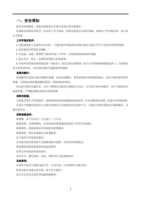
TC55V 运动控制系统1-4轴系列说明书北京多普康自动化技术有限公司安全须知使用本控制系统前,请您仔细阅读本手册后再进行相关的操作。
仔细阅读本操作说明书,以及用户安全须知,采取必要的安全防护措施。
如果用户有其他需求,请与本公司联系。
工作环境及防护:1.控制系统的工作温度为0-40℃,当超出此环境温度时系统可能会出现工作不正常甚至死机等现象。
温度过低时,液晶显示器将出现不正常的情况。
2.相对湿度应控制在0-85%。
3.在高温、高湿、腐蚀性气体的环境下工作时,必须采取特殊的防护措施。
4.防止灰尘、粉尘、金属等杂物进入控制系统。
5.应防护好控制系统的液晶屏幕(易碎品):使其远离尖锐物体;防止空中的物体撞到屏幕上;当屏幕有灰尘需要清洁时,应用柔软的纸巾或棉布轻轻擦除。
系统的操作:系统操作时需按压相应的操作按键,在按压按键时,需要食指或中指的指肚按压,切忌用指甲按压按键,否则将造成按键面膜的损坏,而影响您的使用。
初次进行操作的操作者,应在了解相应功能的正确使用方法后,方可进行相应的操作,对于不熟悉的功能或参数,严禁随意操作或更改系统参数。
由于使用产品不当,而造成危及人身、财产安全的责任,本公司概不负责。
系统的检修:当系统出现不正常的情况,需检修相应的连接或插座连接处时,应先切断系统电源。
再进行必要的检修。
未进行严格操作的技术人员或未得到本公司授权的单位或者个人,不能打开控制系统进行维修操作,否则后果自负。
系统保修说明:保修期:本产品自出厂之日起十二个月内。
保修范围:在保修期内,任何按使用要求操作的情况下所发生的故障。
保修期内:保修范围以外的故障为收费服务。
保修期外:所有的故障均为收费服务。
以下情况不在保修范围内:任何违反使用要求的人为故障或意外故障,尤其电压接反接错。
带电插拔系统连接插座而造成的损坏。
自然灾害等原因导致的损坏。
未经许可,擅自拆卸、改装、修理等行为造成的损坏。
其他事项:本说明书如有与系统功能不符、不详尽处,以系统软件功能为准。
目录目录第一章产品检查及注意事项 (1)1.1开箱检查 (1)1.2运动控制器的型号说明 (1)1.3运动控制器的外形示意图 (2)1.4运动控制器储存环境 (2)1.5运动控制器使用环境 (2)1.6运动控制器的使用注意事项 (3)1.6.1安全注意事项 (3)1.6.2设计方面注意的事项 (3)1.6.3接线方面的注意事项 (3)1.6.4启动、维护时的注意事项 (4)1.6.5废弃时的注意事项 (4)1.7运动控制器的安装注意事项 (4)1.7.1运动控制器的安装方式 (4)1.7.2运动控制器的拆卸 (5)1.7.3运动控制器的摆放 (5)第二章产品介绍 (6)2.1术语与解释 (6)2.2威科达运动控制器简介 (6)2.3典型系统连接图 (7)2.4运动控制器接线端口说明 (7)第三章端子说明及配线 (10)3.1端子定义说明 (10)3.1.1数字IO跳线选择 (10)3.1.2数字量输入接线 (10)3.1.3数字量输出接线 (11)3.1.4RS-232(COM1)接口定义 (12)3.1.5RS-485接口定义 (12)目录3.1.6系统24V供电接口定义 (13)3.1.7数字IO供电接口定义 (13)3.1.8轴接口定义 (14)3.1.9模拟量输入定义 (16)3.1.10模拟量输出定义 (16)3.2运动控制器与伺服驱动器的连接 (17)3.2.1威科达伺服驱动器 (17)3.2.2台达伺服驱动器 (18)3.2.3三菱伺服驱动器 (19)3.2.4富士伺服驱动器 (20)3.2.5松下伺服驱动器 (21)3.2.6安川伺服驱动器 (22)第四章附录 (23)附录一:安装尺寸 (23)附录二:扩展模块概述 (26)第一章产品检查及注意事项第一章产品检查及注意事项1.1开箱检查感谢您选用威科达运动控制器!为了防止产品在购买与运输过程中的疏忽,请仔细检查下列项目:查看产品的铭牌是否与外包装一致;检查产品外观是否有划伤或者机械损伤;查看产品清单,核对配件是否齐全;轻摇机箱,查看内部是否有异物。

PMC100-3运动控制器操作手册第二版(C++版)•2018三英精控(天津)仪器设备有限公司版权申明三英精控(天津)仪器设备有限公司保留所有权利(以下简称三英精控)保留在不事先通知的情况下,修改本手册中的产品和产品规格等文件的权利。
三英精控不承担由于使用本手册或本产品不当,所造成直接的、间接的、附带的或相应产生的损失或责任。
三英精控具有本产品及其软件的专利权、版权和其它知识产权。
未经授权,不得直接或间接地复制、制造、加工、使用本产品及其相关部分。
目录一、概述: (3)二、硬件说明: (4)三、PMC100-3编译器介绍: (7)四、命令介绍: (10)五、附录:样例; (13)一、概述:敬爱的用户:你好!非常感谢您使用PMC100-3步进电机控制器,和国内外同类高档控制器相比,先进的特点如下:1.1、用户编程方便,使用PMC100-3控制器,您不必再为修改程序发愁。
该控制器提供独立的编程环境,不必借助任何工具,您可以随时对程序进行修改或重写。
她的指令设置合理并简单,符合人们的思维习惯,不会在指令的熟悉上浪费您宝贵的时间。
1.2、可控制三轴步进电机。
PMC100-3系列控制器具有驱动最多三轴步进电机的能力,各轴分别带有两个硬件限位点和一个零位。
1.3、显示方式为真彩TFT液晶屏和触摸屏。
1.4、通用2个输入、2个输出点,实现逻辑控制。
1.5、支持控制器计算机下载。
1.6、支持指令控制。
1.7、支持PC机直接控制。
二、硬件说明:2.1、硬件说明1、适用于步进电机的各种场合控制应用。
2、提供运算指令,可进行复杂控制。
3、2个通用输入点、2个输出点,实现逻辑控制。
4、每轴2个硬件限位点。
5、每轴1个零位控制点。
6、默认8细分步进控制,最大256细分。
2.2、性能指标;1、输出脉冲频率:单轴控制400-30000Hz任意值可设定。
2、1K用户程序空间。
3、当前坐标实时显示。
2.3机箱正视图:1、采用2.8寸TFT液晶屏,触摸屏。
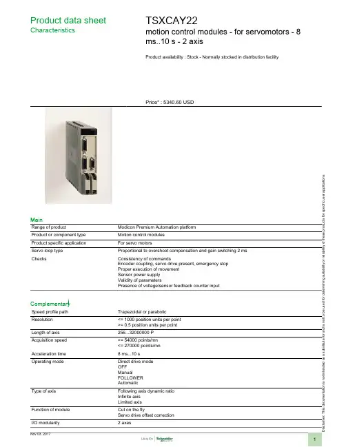
i s c l a i m er : T h i s d o c u m e n t a t i o n i s n o t i n t e n d e d a s a s u b s t i t u t e f o r a n d i s n o t t o b e u s e d f o r d e t e r m i n i n g s u i t a b i l i t y o r r e l i a b i l i t y o f t h e s e p r o d u c t s f o r s p e c i f i c u s e r a p p l i c a t i o n sProduct data sheetCharacteristicsTSXCAY22motion control modules - for servomotors - 8ms..10 s - 2 axisProduct availability : Stock - Normally stocked in distribution facilityPrice* : 5340.60 USDMainRange of productModicon Premium Automation platform Product or component type Motion control modules Product specific application For servo motorsServo loop type Proportional to overshoot compensation and gain switching 2 ms ChecksConsistency of commandsEncoder coupling, servo drive present, emergency stop Proper execution of movement Sensor power supply Validity of parametersPresence of voltage/sensor feedback counter inputComplementarySpeed profile path Trapezoidal or parabolic Resolution <= 1000 position units per point >= 0.5 position units per point Length of axis 256...32000000 P Acquisition speed >= 54000 points/mn <= 270000 points/mn Acceleration time 8 ms...10 s Operating modeDirect drive mode OFF ManualFOLLOWER AutomaticType of axisFollowing axis dynamic ratio Infinite axis Limited axisFunction of module Cut on the flyServo drive offset correction I/O modularity2 axesInput compatibility Absolute encoder SSI output 12...25 bitsIncremental encoder 10...30 V totem poleIncremental encoder 5 V DC RS422With 2-wire/3-wire sensor (24 DC) auxiliary inputAbsolute encoder parallel output ABE7CPA11Clock frequency200 kHz SSI absolute encoderIncremental encoder frequency x1500 kHzIncremental encoder frequency x 41000 kHz in counting250 kHz in inputPower dissipation in W7.2...11.5 WInput type Current sink auxiliary input conforming to EN/IEC 1131 Type 2Resistive counter inputResistive servo drive control input conforming to EN/IEC 1131 Type 1 Input logic PositiveInput voltage24 V 8 mA auxiliary input24 V 8 mA servo drive control input5 V 18 mA counter inputInput voltage limits<= 5.5 V counter input19...30 V auxiliary input19...30 V servo drive control inputVoltage state 1 guaranteed>= 11 V auxiliary input>= 11 V servo drive control input>= 2.4 V counter inputCurrent state 1 guaranteed>= 3.5 mA servo drive control input>= 3.7 mA counter input>= 6 mA auxiliary inputVoltage state 0 guaranteed<= 1.2 V counter input<= 5 V auxiliary input<= 5 V servo drive control inputCurrent state 0 guaranteed<= 1 mA counter input<= 1.5 mA servo drive control input<= 2 mA auxiliary inputInput impedance270 Ohm counter input3000 Ohm auxiliary input3000 Ohm servo drive control inputNumber of outputs 2 analogue output static2 reflex output static conforming to EN/IEC 611312 servo drive validation output relayAnalogue output range+/- 10...24 VAnalogue output resolution13 bits + signLSB value 1.25 mV analogue outputOutput voltage24 V DC reflex output24 V DC servo drive validation outputOutput voltage limits19...30 V reflex output5...30 V servo drive validation outputNominal output current0.5 A reflex outputMaximum output current 1.5 mA analogue output200 mA servo drive validation output625 mA reflex outputMinimum load 1 mA 1 VVoltage drop< 1 V at state on reflex outputLeakage current< 0.3 mA reflex outputSwitching time< 5 ms for servo drive validation< 500 µs for reflex outputOutput compatibility Positive logic DC inputs (resistance <= 15 kOhm) reflexShort-circuit protection Current limiter reflex outputThermal tripping reflex outputOutput overload protection Current limiter reflex outputThermal tripping reflex outputOutput overvoltage protection Zener diode between outputs and 24 DC reflex outputReverse polarity protection Reverse diode on supply reflex outputLocal signalling 2 LEDs green axis diagnostics available1 LED green module operating (RUN)1 LED red external fault (I/O)1 LED red internal fault, module failure (ERR)Electrical connection1 connector HE-10 20 pins for aux inputs, reflex output, for external sensor and preactuator power supply1 connector HE-10 20 pins for servo drive ctrl inputs + for ext power supply of servo drive inputs/outputs1 connector SUB-D 9 for an analogue output (speed reference)2 connectors SUB-D 15 for an incremental or absolute encoder Current consumption1100 mA 5 V DC 15 mA 24 V DC11...20 mA 24 V DC on 10/30 V absolute encoder module Module format StandardProduct weight1.06 lb(US) (0.48 kg)EnvironmentProtective treatmentTCAmbient air temperature for operation 32...140 °F (0...60 °C)Ambient air temperature for storage -13...158 °F (-25...70 °C)Relative humidity 5...95 % without condensation Operating altitude<= 6561.68 ft (2000 m)Ordering and shipping detailsCategory22558 - TSX PREMIUM, ATRIUM & PL7 PRO Discount Schedule PC22GTIN00785901123675Nbr. of units in pkg.1Package weight(Lbs) 2.21Returnability N Country of originFROffer SustainabilitySustainable offer status Not Green Premium productRoHS (date code: YYWW)Compliant - since 0806 - Schneider Electric declaration of conformity Schneider Electric declaration of conformity REAChReference not containing SVHC above the threshold Reference not containing SVHC above the threshold Product end of life instructionsNeed no specific recycling operationsContractual warrantyWarranty period18 monthsDimensions DrawingsStandard and Extendable Racks for Modules MountingDimensions of Modules and Racks(1) With screw terminal block modules.(2) Maximum depth for all types of modules and their associated connectors.Connection of Speed Reference Signals Connector PinoutConnection of Counting SignalsConnectors PinoutsConnection of Sensors/Pre-actuators and Encoder Power Supply, without Variable Speed ControllerHE10 Connector PinoutThe auxiliary inputs/outputs are allocated the following functions:●I0 = cam reference point input,●I1 =emergency stop input (stop if there is no current in the input),●I2 = adjusting input,●I3 = adjustment input,●Q0 = reflex output (static output),●0 V = shared auxiliary inputs and reflex outputs.Connection of the Variable Speed Controller Signals Connector PinoutThe axis command modules implement basic management of the signals necessary for correct operation of the variable speed controllers. Thereis only one connector, regardless of the number of axis command module channels.COMx – VALVARx: potential free contact to validate variable speed controller OK_VARx: variable speed controller input check 24 V – 0 V sensor power supplyNOTE: Each channel uses a potential free closing contact.。

黄石市科威自控有限公司资料编号:20210901-V14第一章安全注意事项 (1)第二章运动控制器选型 (3)2.1主要功能 (3)2.2型号说明 (4)第三章运动控制器安装与尺寸 (5)3.1运动控制器安装 (5)3.1.1安装场所 (5)3.1.2环境条件 (5)3.1.3安装方向与间隔 (5)3.2运动控制器尺寸 (6)第四章运动控制器接口 (7)4.1电源配线 (7)4.2状态识别 (8)4.3开关量输入 (8)4.4开关量输出 (9)第五章PLC 功能 (11)5.1软元件介绍 (11)5.1.1输入输出继电器[X],[Y] (12)5.1.2辅助继电器[M] (13)5.1.3状态继电器[S] (14)5.1.4定时器[T] (15)5.1.5计数器[C] (17)5.1.6数据寄存器[D] (22)5.1.7扩展寄存器[R] (24)5.1.8变址寄存器[V],[Z] (25)5.1.9标记指针[P],[I] (26)5.1.10常数[K],[H] (28)5.1.11掉电保护 (28)5.2基本逻辑指令 (28)5.2.1[LD],[LDI],[OUT]指令 (30)5.2.2[AND],[ANI]指令 (31)5.2.3[OR],[ORI]指令 (32)5.2.4[LDP],[LDF],[ANDP],[ANDF],[ORP],[ORF]指令 (33)5.2.5[ORB]指令 (34)5.2.6[ANB]指令 (35)5.2.7[MPS],[MRD],[MPP]指令 (36)5.2.8[MC],[MCR]指令 (39)5.2.9[INV]指令 (41)5.2.10[ALT]指令 (42)5.2.11[PLS],[PLF]指令 (43)目录5.2.13对应计数器软元件C的[OUT],[RST]指令 (45)5.2.14[NOP],[END]指令 (46)5.2.15编程注意事项 (47)5.3步进顺控指令 (48)5.3.1[STL],[RET]指令 (48)5.3.2分支与汇合 (49)5.3.3循环与跳转 (50)5.3.4步进指令应用示例 (50)5.4常规功能指令 (52)5.4.1条件跳转[CJ] (54)5.4.2子程序调用[CALL]/子程序返回[SRET] (56)5.4.3主程序结束[FEND] (57)5.4.4循环范围开始[FOR]/循环范围结束[NEXT] (58)5.4.5监视定时器[WDT] (60)5.4.6开始比较[LD□] (61)5.4.7并联比较[OR□] (62)5.4.8串联比较[AND□] (63)5.4.9数据比较[CMP] (64)5.4.10区域比较[ZCP] (65)5.4.11传送[MOV] (66)5.4.12成批传送[BMOV] (68)5.4.13多点传送[FMOV] (70)5.4.14高低字节交换[SWAP] (72)5.4.15两个数据交换[XCH] (73)5.4.16批次复位[ZRST] (74)5.4.17反向传送[CML] (76)5.4.18加法[ADD] (77)5.4.19减法[SUB] (78)5.4.20乘法[MUL] (79)5.4.21除法[DIV] (80)5.4.22加1[INC],减1[DEC] (82)5.4.23求平均值[MEAN] (83)5.4.24逻辑与[WAND],逻辑或[WOR],逻辑异或[WXOR] (84)5.4.25求负[NEG] (87)5.4.26开方[SQR] (89)5.4.27循环左移[ROL],循环右移[ROR] (90)5.4.28带进位循环左移[RCL],带进位循环右移[RCR] (92)5.4.29位左移[SFTL],位右移[SFTR] (94)5.4.30字左移[WSFL],字右移[WSFR] (96)5.4.31移位读出[SFRD] (99)5.4.32移位写入[SFWR] (100)5.4.33整型转浮点[FLT] (101)5.4.34浮点转整型[INT] (102)5.4.36二进制转BCD[BCD] (104)5.4.37十六进制转ASCII[ASCI] (105)5.4.38ASCII转十六进制[HEX] (106)5.4.39浮点比较[ECMP] (107)5.4.40浮点区域比较[EZCP] (108)5.4.41浮点加法[EADD] (109)5.4.42浮点减法[ESUB] (110)5.4.43浮点乘法[EMUL] (111)5.4.44浮点除法[EDIV] (112)5.4.45浮点十进制转浮点二进制[EBIN] (113)5.4.46浮点二进制转浮点十进制[EBCD] (114)5.4.47浮点开方[ESQR] (116)5.4.48浮点SIN运算[SIN] (117)5.4.49浮点COS运算[COS] (118)5.4.50浮点TAN运算[TAN] (119)5.4.51浮点ASIN运算[ASIN] (120)5.4.52浮点ACOS运算[ACOS] (121)5.4.53浮点ATAN运算[ATAN] (122)5.4.54浮点RAD运算[RAD] (123)5.4.55浮点DEG运算[DEG] (124)5.4.56输入输出刷新[REF] (125)5.4.57PID控制[PID] (127)5.5中断系统 (130)5.5.1中断资源介绍 (130)5.5.2中断执行流程 (130)5.5.3中断指令[EI],[IRET],[DI] (132)5.5.4中断嵌套 (133)5.5.5定时器中断 (134)5.5.6外部输入中断 (135)5.5.7系统软中断 (136)5.5.8高级中断 (137)5.6虚拟示波器 (141)5.6.1触发方式 (141)5.6.2触发单元 (142)5.6.3触发门限 (142)5.6.4采样周期 (142)5.6.5采样点数 (142)5.6.6记录起始寄存器序号 (143)5.6.7记录区间起始寄存器序号 (144)5.6.8记录区间终止寄存器序号 (144)5.6.9示波器状态设置/显示 (145)5.6.10当前采样点 (145)5.6.11通道工作模式 (145)5.7特殊辅助继电器[M],特殊数据寄存器[D] (147)5.7.1特殊辅助继电器[M]功能一览表 (147)5.7.2特殊辅助寄存器[D]功能一览表 (154)第六章通信功能 (161)6.1通信原理 (161)6.1.1通信方式 (161)6.1.2网络系统结构 (162)6.2串口初始化[UINIT] (164)6.3计算机链接协议 (166)6.3.1通信格式 (166)6.3.2任务调度配置 (169)6.3.3通信示例 (171)6.4MODBUS协议 (173)6.4.1通信格式 (173)6.4.2软元件通信地址 (174)6.4.3MODBUS指令 (174)6.4.4通信示例 (184)6.5自由协议 (185)6.5.1任务调度配置 (185)6.5.2自由协议指令 (187)6.5.3通信示例 (189)6.6其他协议 (191)第七章扩展模块 (192)7.1扩展寄存器 (192)7.2模拟量模块 (193)7.2.1模块规格 (193)7.2.2模块读写控制 (195)7.2.3输入模拟量 (196)7.2.4输出模拟量 (196)7.3开关量模块 (198)7.3.1模块规格 (198)7.3.2模块读写控制 (200)第八章运动控制 (201)8.1运动控制指令 (201)8.2运动轴对象 (202)8.2.1运动轴定义 (202)8.2.2运动输入轴参数配置 (203)8.2.3运动输出轴参数配置 (204)8.3单轴基本运动 (217)8.3.1回原点[HOME] (218)8.3.2点动[JOG] (221)8.3.3定位[PSOUT] (225)8.3.4制表[PTAB] (227)8.3.6插补[IPL] (238)8.3.7定速定长输出[DPLSY] (240)8.3.8加减速定长输出[DPLSR] (242)8.3.9相对定位[DDRVI] (244)8.3.10绝对定位[DDRVA] (246)8.3.11中断定位[DDVIT] (248)8.3.12变速输出[DPLSV] (250)8.3.13高速读出[DHMOV] (252)8.3.14高速比较置位[DHSCS] (253)8.3.15高速比较复位[DHSCR] (255)8.3.16高速区间比较[DHSZ] (257)8.3.17高速表格比较输出[DHSCT] (259)8.4单轴关联运动 (261)8.4.1电子齿轮[GEAR] (261)8.4.2电子凸轮[CAM] (264)8.4.3追剪正程/滚切制表[PCTAB] (283)8.4.4追剪返程制表[PBTAB] (289)安全警告和标识第一章安全注意事项警告标识含义该标识表示若操作错误则可能发生“死亡或重伤”该标识表示若操作错误则可能发生“人身伤害或财产损害”安全标识含义该图形表示“不可实施”的内容该图形表示“必须实施”的内容切勿在有水的地方、存在腐蚀性、引火性气体的环境内以及可燃物旁使用,容易发生火灾不要在振动和冲击激烈的地方使用不要用湿手进行接线和设备操作切勿将手伸入运动控制器内部不要使导线受到损伤或承受过大的外力、重压、受夹切勿用裸手检查伺服接线故障,容易引发触电应在尘埃较少,不会接触到油、水的地方放置请进行正确的接线,否则可能发生火灾或故障导线应连接好,通电部位须通过绝缘套做到绝缘运动控制器必须实际接地外部应设置紧急停止电路,以确保紧急时可及时地停止运转、切断电源运动控制器的移动、接线、检查等要在切断电源并确保放电结束后没有触电危险的前提下进行必须设置过电流保护装置、漏电断路器、温度防护装置以及紧急停止装置安全注意事项不要在运动控制器上放置重物不要使运动控制器受到较强的冲击不要频繁地开、关主电源不要对运动控制器进行长时间极限情况测试切勿自行改造、分解、修理严格按照正确的安装方法安装运动控制器确保运动控制器在规定的温度和湿度范围内运行发生故障时请清除故障、确保安全后再重新运行运动控制器发生故障时请切断电源第二章运动控制器选型2.1主要功能●掉电数据保存掉电保存数据功能,运动控制器可以在断电时自动保存用户数据。
Modicon Quantum Automation Series MSx Motion Module Reference Guide840 USE 105 00 Version 3.0February , 1996AEG Schneider Automation, Inc. One High Street North Andover , MA 01845PrefaceThe data and illustrations found in this book are not binding. We reserve the right to modify our products in line with our policy of continuous product development. The information in this document is subject to change without notice and should not be construed as a commitment by AEG Schneider Automation, Inc. AEG Schneider Automation assumes no responsibility for any errors that may appear in this document. If you have any suggestions for improvements or amendments or have found errors in this publication, please notify us by using the form on the last page of this publication. No part of this document may be reproduced in any form or by any means, electronic or mechanical, including photocopying, without express written permission of the Publisher, AEG Schneider Automation, Inc.Caution: All pertinent state, regional, and local safety regulations must be observed when installing and using this product. For reasons of safety and to assure compliance with documented system data, repairs to components should be performed only by the manufacturer .MODSOFTâ is a registered trademark of AEG Schneider Automation, Inc. The following are trademarks of AEG Schneider Automation, Inc.: Modicon Modbus Plus Modbus II Compact 984 PLC P230 Quantum Automation Series Modbus 984 Modicon Micro PLC P190DIGITALâandDECâareregisteredtrademarksofDigitalEquipment Corporation. IBMâ and IBM ATâ are registered trademarks of International Business Machines Corporation. Microsoftâ and MS DOSâ are registered trademarks of Microsoft Corporation. ã Copyright 1995, AEG Schneider Automation, Inc. Printed in U.S.A.840 USE 105 00PrefaceiiiContentsChapter 1 Overview .................................................. 1.1 Related Publications . . . . . . . . . . . . . . . . . . . . . . . . . . . . . . . . . . . . . . . . . . . .1 2Chapter 2 Specifications 2.1and HardwareOverview......................3 4 6 7 9 11 13 152.2MSx Motion Modules . . . . . . . . . . . . . . . . . . . . . . . . . . . . . . . . . . . . . . . . . . . 2.1.1 Front Panel Indicators . . . . . . . . . . . . . . . . . . . . . . . . . . . . . . . 2.1.2 Front Panel Connectors . . . . . . . . . . . . . . . . . . . . . . . . . . . . . . 2.1.3 Rear Panel Switches . . . . . . . . . . . . . . . . . . . . . . . . . . . . . . . . . 2.1.1 Operational Specifications . . . . . . . . . . . . . . . . . . . . . . . . . . . 2.1.2 Electrical Specifications . . . . . . . . . . . . . . . . . . . . . . . . . . . . . Breakout Module . . . . . . . . . . . . . . . . . . . . . . . . . . . . . . . . . . . . . . . . . . . . . . .Chapter 3 System Information 3.1 3.2 3.3.........................................17 18 19 20Flash Memory . . . . . . . . . . . . . . . . . . . . . . . . . . . . . . . . . . . . . . . . . . . . . . . . . Communications Protocol . . . . . . . . . . . . . . . . . . . . . . . . . . . . . . . . . . . . . . . On-line and Off-line Development with MMDS . . . . . . . . . . . . . . . . . . . .Appendix A Parts List . . . . . . . . . . . . . . . . . . . . . . . . . . . . . . . . . . . . . . . . . . . . . . . . . . Appendix Hardware B.1 B Installation21.......................................23 24 27 31Mounting and Connecting the MSx Modules . . . . . . . . . . . . . . . . . . . . . . B.1.1 Motion Cables . . . . . . . . . . . . . . . . . . . . . . . . . . . . . . . . . . . . . . ......................................................Index840 USE 105 00ContentsvviContents840 USE 105 00Chapter 1 OverviewThe Quantum Automation Series single axis motion (MSx) modules (140 MSB 101 00 and 140 MSC 101 00) are designed to control a single axis of motion using advanced digital brushless motion control. This capability provides optimal control by eliminating potentiometer adjustments and analog velocity loops. The MSx modules are designed to interface directly to the Modicon Cyberline 1000 series brushless servo amplifiers as well as other types of dc and brushless drives.Note:These modules are designed to serve your many and varied applications with great accuracy and speed. However, certain applications might be outside the scope of this module. Please consult Modicon for applications information if you intend to use the module specifically for precise velocity control. The primary feedback used by the direct numeric processing (DNP) servo system is position information from either a resolver or an encoder mounted to the motor. Velocity information is derived from the position information, rather than being received from a velocity transducer. This leads to some inaccuracies when using the DNP servo as a velocity controller. Small speed irregularities may result, particularly at slower speeds. If a CL1000D drive is used, this will probably not be an issue as the CL1000D drive uses software techniques that give the overall system good velocity regulation.Note:840 USE 105 00Overview11.1RelatedPublicationsIn addition to this manual, you will need: V VSingle Modicon Axis Software Motion System (SASS) Motion User Guide User GuideDevelopmentSoftware(MMDS)The Single Axis Software System (SASS) Motion User Guide provides a comprehensive description of Modicon single-axis motion control systems and important system design and performance information. It also presents the SASS programming language, including instructions for setting up and configuring your applications. The Modicon Motion Development Software (MMDS) User Guide presents basic instructions for installing, initializing, and using this intuitive, interactive, menu-driven tool. MMDS helps you create, test, debug, and maintain your application programs. Other related documents include: V V VCyberline Cyberline Quantum 1000A 1000D System Design and Installation ManualDrive User Guide Series Hardware Reference GuideAutomation2Overview840 USE 105 00Chapter 2 Specifications Overviewand HardwareV VMSx Motion Modules Breakout Module840 USE 105 00Specificationsand HardwareOverview32.1MSx MotionModulesThe Quantum single axis motion (MSx) modules are incremental encoder (140 MSB 101 00) or resolver and encoder (140 MSC 101 00) feedback-only modules contained in a single-width housing. It works with servo motors that use Cyberline drives and other types of DC and brushless drives from other manufacturers. The illustration below shows a typical configuration of a single axis motion control system.MMDS on PC or Compatible Quantum CPU Modbus (for programming)Quantum BackplaneMSx ModuleBreakout ModuleAnalog I/OAdditional Discrete I/ODriveMotor FeedbackLimitsLimitsMotor Load4Specificationsand HardwareOverview840 USE 105 00The modules contain I/O to interface to the drive and the machine, including drive enable, drive fault, and a variety of user-configurable signals. The modules also include a high speed input pin to perform high speed position capture. See below for an illustration of the Quantum MSx module.MSx modules are only installed in Quantum backplanes. Refer to the Quantum Automation Series Hardware Reference Guide (840 USE 100 00) for detailed specifications of all Quantum modules and associated hardware.Note:840 USE 105 00Specificationsand HardwareOverview52.1.1Front Panel IndicatorsThere are seventeen LED indicators visible on the front panel:140 MCX 101 00 LED IndicatorsLEDs Active Ready + Lim ok Lim ok Active Ready +Lim ok Lim ok Home In 4 In 5 In 6 In 7 Drv Flt Drv En Out 1 Out 2 Out 3 Modbus Moving In Pos Home In 4 In 5 In 6 In 7 Drv Flt Drv En Out 1 Out 2 Out 3 Modbus Moving In Pos Color Green Green Green Green Green Green Green Green Green Red Green Green Green Green Green Amber Amberand DescriptionsIndication when On Bus communication is present. The module has passed powerup diagnostics. Digital Input 1 active. Digital Input 2 active. Digital Input 3 active. Digital Input 4 active. Digital Input 5 active. Digital Input 6 active. Digital Input 7 active. Fault signal from drive. Drive enabled. Digital Output 1 active. Digital Output 2 active. Digital Output 3 active. Communications are active on the Modbus port. Motor is moving. Motion is within the in position of the final target.6Specificationsand HardwareOverview840 USE 105 00Specifications and Hardware Overview 840USE 1050072.1.2Front Panel ConnectorsThere are two connectors located on the front of the module:ModbusConnectorThe MSx modules are equipped with a 9—pin RS 232C connector that supports Modicon’s proprietary Modbus communication protocol.The following is the Modbus port pinout connections for 9—pin and 25—pin connections.Signal MSx Pin Signal Function 112No Connection3TXD RXD 32RXD TXD 55GND GND 77RTS RTS 88CTSCTSShieldSerial data Serial data Ground Control line Control lineMSx ModbusPort Pinoutsto 9—PinConnectors(AS W956xxx)46DTR DSR 64DSR DTR Control line Control line ComputerPinSignal MSx Pin ComputerPinSignal Function 112No Connection2TXD RXD 33RXD TXD 57GND GND 74RTS RTS 85CTSCTSShieldSerial data Serial data Ground Control line Control lineMSxModbus Port Pinouts for 25—Pin Connectors (AS W955xxx)46DTR DSR 620DSR DTR Control line Control lineSpecificationsand HardwareOverview840USE 105008Servo ConnectorThe MSx is also equipped with a 50—pin servo connector for communication with feedback devices.Note:The tables below show the 50pin servo connector signals.Pinnumbers correspond to both the MSB and MSC modules.When the signals differ from each other,they are shown separated by a slash (i.e.,Pin Number 34,MSB/MSC).Servo Connector Signals (from left to right)5034N /CN /C /R e f e r e n c e O u t p u t L o wN /C /R e f e r e n c e O u t p u t H i g hN /C /S i n e I n p u t L o wN /C /S i n e I n p u t H i g hN /C /C o s i n e I n p u t L o wN /C /C o s i n e I n p u t H i g hO v e r t e m p L o wO v e r t e m p H i g hD r i v eE n a b l e C o m m o nD r i v eE n a b l e C o n t a c t (N C )D r i v eE n a b l e C o n t a c t (N O )D r i v e F a u l tV e l o c i t y/P h a s e C o m m o nN /C /P h a s e CN /C /P h a s e BV e l o c i t y +/P h a s e A5049484746454443424140393837363534Servo Connector Signals (from left to right)3318Servo Connector Signals (from left to right)171N /C (N o t C o n n e c t e d )N /CN /CN /CN /CE n c o d e r 2M a r kE n c o d e r 2M a r k +E n c o d e r 2P h a s e BE n c o d e r 2P h a s e B +E n c o d e r 2P h a s e A E n c o d e r 2P h a s e A +E n c o d e r 1M a r kE n c o d e r 1M a r k +E n c o d e r 1P h a s e BE n c o d e r 1P h a s e B +E n c o d e r 1P h a s e AE n c o d e r 1P h a s e A +17161514131211109876543212.1.3Rear Panel SwitchesThe MSx has an RS-232serial port to connect the module to an IBMPC(or compatible)running the Modicon Motion Development Software(MMDS).A two-position DIP switch is located on the rear panel of themodule(below).SW1is used to specify the module’s operating mode(984or MMDS control).SW2is used to specify the communicationpower-up.characteristics of the Modbus port uponSpecifications and Hardware Overview840USE105009Specifications and Hardware Overview840USE 1050010 4.When the Set Local Lockout command is not issued and both the Compact 984and MMDS are communicating to the module,the setting of SW1controls which device has write privilege.Note:Either device may read—that is,issue a GET command—atany time.However,reading the error log (a system command)is not allowed without write privilege because the log is lost once it has been read.See the Single Axis Software System (SASS)Motion User Guide for details.2.1.3.2Setting Modbus Comm Characteristics with SW2The SW2setting determines the Modbus communicationcharacteristics.When the module is powered up,SW2is read.When the switch is closed,the default characteristics are used.When theswitch is open then the communication characteristics last saved in the module are used.Once communication characteristics are initialized,they may bechanged at any time under software control only if SW2is in the open position.See the Single Axis Software System (SASS)Motion User Guide for details.When SW2is closed,these Modbus port default characteristics are used:V One start bit V Seven data bits V One stop bitV Even parity checking V9600baudSpecifications and Hardware Overview 840USE 10500112.1.1OperationalSpecificationsServoCommutation Update Rate 0.25ms Velocity Loop Update Rate 0.5ms Velocity Loop Bandwidth >100Hz Velocity Range6000rpm Position Loop Update rate 1msPosition Accuracy Resolver+10arc minutes typical,+15arc minutes max Position RepeatabilityResolver +5arc minutes maxPosition AccuracyEncoderEncoder dependent,0.5arc minutes maxCommunicationProtocolModbus Address (set by software)1default Baud Rate (set by software)30019200baud,9600defaultApplicationProgramExecution Rate See note below Storage650instructionsNote:A majority of the instructions typically take 1ms to execute.The execution time of an instruction,though,is not constant.The execution time can increase due to factors such as:if the Sync Ratio Mode is on,how often the position generator must execute to plan out new moves,how many whenevers are enabled,the number of sources requesting commands be executed (e.g.,backplane,internal program,Modbus port),etc.If timing is extremely critical to an application,actual time must be determined experimentally by running the actual application program.High Speed InputPosition Capture Time 250s max Isolation 500V to system bus Pulse Width25s Minimum Time Between Successive Captures20msDiscreteInputsNumber 7Scan Time 1.5msIsolation500V to system busSpecifications and Hardware Overview840USE 1050012Discrete OutputsNumber 3Update Time 10ms maxIsolation 500V to system bus Reset State 0V,nominal On State 24V,nominalOutput Type Totem pole (sink/source)Protection Short circuit,overvoltage FaultOvercurrent detectedAnalogInputNumber 1Scan Time 15msData User configurable Range +10VAccuracy+100mV,plus offsetAnalogOutputNumber 1Scan Time 20msData User configuable Range +10VAccuracy+50mV,plus offsetResolverFeedback(Fully ConfiguredVersion)Conversion Method Tracking Resolver Style Transmit Excitation Frequency 5kHzExcitation Amplitude Automatically adjusted Excitation Current 120mALoss of FeedbackDetected within 40msIncrementalEncoderFeedbackResolution 4times line count SignalsA,B,MarkSignal Frequency 200kHz,up to 500kHz with reduced noise immunity Encoder Output style Differential,5V Loss of FeedbackDetected within 40ms2.1.2Electrical SpecificationsDiscrete Inputs and High Speed InputInput Impedance 3.5kInputs On15Vdc minInputs Off5Vdc maxIsolation500Vac to system busDiscrete OutputDrive Capability150mA at user supplied19.2...30VdcresistiveProtection Current limit,thermalIsolation500Vac to system busAnalog InputResolution10bitsInput Impedance30kOffset+50mVAccuracy+100mV,plus offsetAnalog OutputResolution12bitsDrive Capability3mAOffset+50mVAccuracy+50mV,plus offsetResolver InterfaceReference5+0.05kHz,1.6...5.5V rms50mA drive capabilitySine/Cosine Input Impedance3kResolution16bits to300rpm14bits to1350rpm12bits to6000rpmAccuracy10arc minutes,typical,resolver dependentMotor Temperature InputNormal State Short circuit,2mA sink maxFault State Open circuitIsolation500Vac to system busSpecifications and Hardware Overview840USE1050013Specifications and Hardware Overview840USE 1050014Encoder Feedback InterfaceInput Range 0.7...7Vdc Input Impedance 145,nominal Differential Signals,High +2V differential,min Differential Signals,Low 2V differential,minMaximum Encoder Frequency 200kHz square wave(55%...45%with less than 15_of quadrature error)Isolation500Vac to system bus with external power supply Minimum Encoder Pulse Width1msDrive InterfaceDrive Fault Input True high,TTL compatible relative to remote common,10K internal pull up resistor Drive Enable RelayForm C contacts120Vac @0.1A resistive 30Vdc @0.5A resistive Current Command Voltages+10Vdc Current Command Summing Accuracy 0+0.1VdcCurrent Commands3mA drive capabilityPower RequirementsMain Power Input 5V +5%@750mA(with no encoders or resolvers attached,output off)Main Power Input 5V +5%@1000mA(with maximum encoder and resolver load,outputs on)Hot Swap Surge CurrentLess than 5ASpecifications and Hardware Overview 840USE 10500152.2Breakout ModuleThe Breakout Module (see below)is the I/O wiring block connector for the 140MSx 10100Single Axis Motion Module servo connections.It is connected to the MSx via a Breakout Module cable (690MCI 000xx)at the 50pin servo connector.Refer to the previous section for a description of the servo connectorsignals.Note:Provided with the Breakout Module are labels for the MSBand MSC modules (see Appendix B).These labels are a reference for the Breakout Module signal names.Attach the applicable label near this Breakout Module in your cabinet orrack.Specifications and Hardware Overview840USE 1050016A Breakout Module cover (below),Modicon #690MCB 10100,is also available,which shields the termination points of the breakout module from electrostatic discharge.It is a metal plate that is screwed down to the same panel as the DIN rail that holds the Breakout Module.This cover is required to make the system CE *compliant (refer to Appendix B for installationinstructions).*The CE mark indicates compliance with the European Directive on Electromagnetic Compatibility (EMC)(89/336/EEC).In order to maintain compliance,the Quantum system must be installed per the installation instructions.Chapter 3 System InformationV V VFlash Memory Communications Protocol On-line and Off-line Development with MMDS Refer to Appendix E in the Single Axis Software System User Guide for system checkout information.Note: (SASS)Motion840 USE 105 00SystemInformation173.1Flash MemoryThe MSx comes with a flash EEPROM that allows storage of application programs and configuration parameters such as servo parameters, speed limits, etc. The flash also accepts firmware updates as firmware enhancements become available.18SystemInformation840 USE 105 003.2CommunicationsProtocolBackplane communications with the MSx is through six 3x and 4x registers, which must be I/O mapped to the MSx. Modbus communication with the MSx is through six pairs of registers via the Modbus communication link. The register format is very rigid. The first register sent to the module (4X)is always the control register, and the second is always the command register. The first register returned from the module (3X) is always the current status of the module, while the second register returned is always an echo of the command register. All remaining registers, data register 1 ... 4, are reserved for data and are used as necessary. For additional information refer to Single Axis Software System (SASS) Motion User Guide .840 USE 105 00SystemInformation193.3On-line MMDSand Off-lineDevelopmentwithThe Modicon Motion Development Software (MMDS), Version 4.1 or higher, is an on-line/off-line software package which runs on a user-supplied IBM PC or compatible computer. MMDS is purchased separately. The computer with MMDS can be connected to the MSx through an RS-232 serial interface. With MMDS, you can set parameters, check module diagnostics, and exercise the motor during initial system setup. You can also write motion programs and download them into the MSx directly.Note: If the module is I/O mapped in a Quantum PLC and the user has a Modbus Plus adaptor card in their PC, it is possible to do on line development over the Modbus Plus network. Refer to the Modicon Motion Development Software (MMDS) User Guide for details.20SystemInformation840 USE 105 00Appendix A Parts ListPart NumberDescription140 MSB 101 00 140 MSC 101 00 690 MCB 000 00 690 MCB 101 00 690 MCI 000 01 690 MCI 000 03 690 MCI 000 06Quantum Motion Module Quantum Motion Module Breakout Module, 50 Signal CE Compliant Breakout Module Cover Low profile DB50/DB50 cable, 1 ft Low profile DB50/DB50 cable, 3 ft Low profile DB50/DB50 cable, 6 ft840 USE 105 00Parts List21A.122Parts List840 USE 105 00Appendix HardwareB InstallationVMounting and Connecting the MSx Modules840 USE 105 00HardwareInstallation23B.1Mounting Modulesand Connectingthe MSxThe MSx modules can be inserted into any slot of any backplane and removed under power (hot swapped) without damaging modules or the backplane (Quantum power supply modules must be installed in the first or last slots of the backplane). Refer to the following figures and procedure when mounting modules.Note:For the required grounding configurations for the single axis motion modules, refer to Appendix D of the Quantum Automation Series Hardware Reference Guide .1 2Select a Quantum backplane. Remove the backplane connector cover(s).Backplanes are designed to mechanically secure and electrically connect all modules used in drops. The backplane contains a passive circuit board which permits modules to communicate with each other and to identify their slot numbers without further switch settings.Note:To meet vibration/shock specifications, the backplane must be mounted using all specified mounting holes. The backplane is mounted using standard hardware (described below). The recommended length for the mounting screws should be within the following range: 0.24 in (6 mm) 0.52 in (13 mm )The head height of the screws should not exceed 0.14 in (3.5 mm).24HardwareInstallation840 USE 105 00Hook3Backplane ConnectorMount the MSx at an angle on to the two hooks located near the top of the backplane. Swing the MSx down to make an electrical connection with the backplane I/O bus connector. Tighten the screw at the bottom of the MSx to fasten it to the backplane.The maximum tightening torque for these screws is 2 4 in lbs.4MSx Module5BackplaneMSx Servo Connector6Once installed, connect the MSx, using a 690 MCI 000 0x breakout cable to the breakout module as follows. Reverse the order of these steps to remove breakout cable.a.690 MCI 000 0x CableAs shown in this illustration, line up the connector on the MSx and push the cable firmly into the connector. Once the cable is secured to the connector, tighten the screws onto the connector. Plug the other end of the cable into the breakout module using the same procedure as above.b.c.MSx Breakout Module840 USE 105 00HardwareInstallation257When installing a system that must meet the European CE* Approval Standards, the following special wiring techniques are required:a.The Breakout Module Cover (Modicon # 690 MCB 101 00) must be installed over the Breakout Module after field wiring has been completed in order to shield the termination points from electrostatic discharge. The cover should be placed over the Breakout Module so as to completely cover the terminals and should be screwed down on the same panel as the DIN rail that supports the Breakout Module. If the analog input is used, the twisted shielded pair (Belden 8451, Alpha 2462, or equivalent) for the analog input signal should be stripped about 12 inches back from the Breakout Module to expose the shield. The exposed shield should then be attached to the grounded mounting panel using a Grounding Cable Rail (Modicon # 043509693). In addition, two ferrite beads (Steward # 2880686 200 or equivalent) should be placed over the analog input cable between the grounding cable rail and the Breakout Module.b.c.d. e.bBreakout Module DIN Railcae dPanel Breakout Module Cover*The CE mark indicates compliance with the European Directive on Electromagnetic Compatibility (EMC) (89/336/EEC). In order to maintain compliance, the Quantum system must be installed per the installation instructions.840 USE 105 0026HardwareInstallationHardware Installation 840USE 1050027d.Apply the applicable label (MSB or MSC shown below)to the cabinet or rack as a reference for breakout module connection names.Modicon 140MSB 10100Connections 1CH2A+1824VDC 34VEL+2CH2A 1924Com 35N/C 3CH2B+20Brake 36N/C 4CH2B 21OUT 237VEL 5CH2M +22OUT 338Drv Flt 6CH2M 23CW Lim 39EN NO 7CH3A+24CCW Lim 40EN NC 8CH3A 25Home 41EN Com 9CH3B+26IN 442OTemp +10CH3B 27IN 543OTemp 11CH3M+28IN 644N/C 12CH3M 29IN 745N/C 13N/C 30HSI 46N/C 14N/C 31AN OUT 47N/C 15N/C 32AN Com 48N/C 16N/C 33AN IN 49N/C 17N/C 50N/C Modicon 140MSC 10100Connections 1CH2A+1824VDC 34ØA 2CH2A 1924Com 35ØB 3CH2B+20Brake 36ØC 4CH2B 21OUT 237ØCOM 5CH2M +22OUT 338Drv Flt 6CH2M 23CW Lim 39EN NO 7CH3A+24CCW Lim 40EN NC 8CH3A 25Home 41EN Com 9CH3B+26IN 442OTemp +10CH3B 27IN 543OTemp 11CH3M+28IN 644COS+12CH3M 29IN 745COS 13N/C 30HSI 46SIN+14N/C 31AN OUT 47SIN 15N/C 32AN Com 48REF+16N/C 33AN IN 49REF 17N/C 50N/CHardware Installation 28840USE 10500B.1.1Motion CablesThese tables include signal,pin,and wire information for the AS W9200XX and AS W9220XX module cables.AS W9200XX Cable (for connection to the DB25connector on CL1000A drives)Signal QMOT Breakout/Pin #W ire Color W920W ire Number CL1000A Connector Phase A 34Black 38Phase B 35White 19Phase C 36Blue 210Phase Com 37Orange 414Fault 38Yellow 822Enable N/O 39Green 520Enable Com 41Brown 615Shield Ground *Gray 9Shield AS W9220XX Cable (for the encoder signal from CL1000D drives)Signal QMOT Breakout/Pin #Ch.2Ch.3W ire Color W922W ire Number CL1000D Connector A+17White 22A 28Brown 77B+39Blue 33B 410Green 88M+511Orange 44M 612Violet 99Shield Ground *Bare Shield Shield Not Connected Black 11Not Connected Yellow 55Not Connected Red 66Not Connected Gray 1010*Refer to the breakout module diagram in Section 2.2.Hardware Installation 840USE 1050029Breakout Feedback Cables This table includes the signal,pin,and wire information for the 120169xx,120125xx,and the 120063xx resolver signal cables.These cables carry the resolver signal back to the breakout module from the motor.Signal MCx Pin Letter Designation 120169xx 120125xx 120063xx Reference +48O White White White Reference Com 49G Black Black Black Sine +46E Red Red Red Sine Com 47F Black Black Black Cosine +44I Green Green Green Cosine Com 45H Black Black Black Thermal High 42D Blue Black Red Thermal Low 43J Black Orange Green Brake High 20P Yellow Green Orange Brake Low 19N Black Red Black These cables are designated for dual resolvers,and as such,will have several wires not terminated when used with the MSx modules.This table includes the signal,pin,and wire information for the MC SSXX xx and MC TSXX xx cables.Signal MCx Pin Letter Designation SSXX TSXX Reference +48O White White Reference Com 49G Black Black Sine +46E Red Red Sine Com 47F Black Black Cosine +44I Green Green Cosine Com 45H Black Black Thermal High 42D Blue Black Thermal Low 43J Black Orange Brake High 20P Yellow Green Brake Low 19N Black Red。
AX系列运动控制指令手册Revision History版本修订一览表版本变更内容发行日期第一版第一版发行2020/10/16第二版1. 更新第2.1.1 ~ 2.1.18、2.2.1 ~ 2.2.16、2.3.1.1 ~ 2.3.1.9、2.3.1.11、2.3.2.1 ~ 2.3.2.2、2.3.2.5 ~ 2.3.2.22节:新增支持型号AX-364E2. 更新第2.3.1.1、2.3.1.3 ~ 2.3.1.8、2.3.2.1 ~ 2.3.2.2、2.3.2.5 ~2.3.2.11、2.3.2.15 ~ 2.3.2.16节:更新ErrorID3. 新增第2.3.1.10、2.3.1.12、2.3.1.13、2.3.2.3 ~ 2.3.2.4节4. 更新第2.3.1.11节:更新bInVelocity & bDone5. 更新第2.3.2.6节:更新GroupErrorID6. 更新第2.3.2.12节:更新dwErrorID7. 更新第2.3.3.1 ~ 2.3.3.16节:删除支持型号AX-8并新增支持型号AX-364E8. 更新附录A1:新增DMC_ImmediateStop_P、DMC_GroupInterrupt、DMC_GroupContinue、DMC_GroupReadParameter、DMC_GroupWriteParameter9. 更新附录A2:更新DMC_GROUP_TRANSITION_MODE新增DMC_GROUP_PARAMETER10. 更新附录A.3.111.更新附录A.3.22021/02/28第三版1. 更新第2.3.2.22节:更新bWindowOnly、lrFirstPosition、lrLastPosition的生效时机2. 更新第2.3.3节:增加定位轴速度范围介绍3. 更新第2.3.1.1节:更新范例程序图4.更新第2.3.3.1节:更新bStatus状态时机2021/07/30第四版1. 更新第2.3.1.1节:更新DMC_TorqueControl运动行为说明图示2. 更新第2.3.1.2节:更新输入参数注解3. 新增第2.3.1.14 ~ 2.3.1.18节4. 新增第2.3.2.23 ~ 2.3.2.26节5. 新增第2.4.1节: 新增伺服冲床指令介绍6.更新附录A.2 & A.3 : 新增数据类型说明与错误码说明2022/05/31第五版1. 新增第1.3节:新增台达运动指令库相关说明2. 更新第2.3.1.12节:新增lrDeceleration、lrJerk说明3. 更新第2.3.2.15节:新增和修改功能块参数4. 更新第2.3.2.21节:新增Harmonic2_Direct、Harmonic2_Inverse曲线说明5. 更新第2.3.2.24节:新增单轴位置说明6. 新增第2.3.2.27节:新增DMC_GroupPower说明7. 新增第2.3.4节:新增张力控制8.更新附录A.1、A.2、A.3:新增指令及数据类型说明与错误码说明2022/09/15版本变更内容发行日期第六版1. 更新第2.1.1节:修正功能说明2. 更新第2.3.1、2.3.2节:新增版本匹配错误解决方式3. 更新第2.3.1.1节:修正功能说明4. 更新第2.3.4.1~2.3.4.3节:新增Library支持版本5. 新增第2.3.2.29节:新增DMC_GetCamSlaveData2023/03/31目录前言11.1简介 (2)适用产品 (2)相关手册 (2)第1章运动控制指令介绍 (3)1.1运动控制指令 (4)1.1.1运动控制指令基本原则 (4)1.2运动控制指令分类 (7)1.3台达运动指令库相关说明 (8)第2章运动控制指令 (9)2.1运动型控制指令 (10)2.1.1MC_Home (10)2.1.2MC_Stop (14)2.1.3MC_Halt (16)2.1.4MC_MoveAbsolute (21)2.1.5MC_MoveRelative (27)2.1.6MC_MoveAdditive (31)2.1.7MC_MoveSuperImposed (35)2.1.8MC_CamIn (39)2.1.9MC_CamOut (56)2.1.10MC_MoveVelocity (61)2.1.11MC_PositionProfile (66)2.1.12MC_AccelerationProfile (70)2.1.13MC_VelocityProfile (74)2.1.14MC_Jog (78)2.1.15MC_GearIn (81)2.1.16MC_GearOut (85)2.1.17MC_GearInPos (89)2.1.18MC_Phasing (94)2.2管理型运动控制指令 (99)2.2.1MC_Power (99)2.2.2MC_SetPosition (105)2.2.3MC_ReadParameter (111)2.2.4MC_WriteParameter (114)2.2.5MC_ReadBoolParameter (117)2.2.6MC_WriteBoolParameter (120)2.2.7MC_ReadActualPosition (122)2.2.8MC_ReadActualVelocity (125)2.2.9MC_ReadActualTorque (128)2.2.10MC_Reset (129)2.2.11MC_ReadStatus (132)2.2.12MC_ReadAxisError (137)2.2.13MC_CamTableSelect (140)2.2.14MC_TouchProbe (144)2.2.15MC_AbortTrigger (151)2.2.16MC_DigitalCamSwitch (155)2.2.17SMC_BacklashCompensation (162)2.3台达定义运动型控制指令 (168)2.3.1运动型控制指令 (168)2.3.2管理型运动控制指令 (280)2.3.3定位轴控制指令 (399)2.3.4张力控制 (452)2.4行业专用指令 (477)2.4.1伺服冲床指令 (477)附录514A.1指令列表索引 (515)A1.1依照功能 (515)A1.2依照机种 (520)A1.3依照字母 (523)2.5 A.2数据类型:枚举与结构体 (526)A.3错误码与故障排除 (532)A3.1同步轴错误码与故障排除 (532)A3.2定步轴错误码与故障排除 (549)A.4DMC_H OME_P回原点模式说明 (555)前言1.1简介感谢您购买AX系列运动控制器,并采用我们为您提供的高端运动控制系统。
/DVP-1191470-01………………………………………………………………… ENGLISH …………………………………………………………………… Thank you for choosing Delta DVP-MC series motion controller. DVP-MCseries is a multi-axis motion controller based on CANopen fieldbus and can be applied in packaging machines, printing machines, taping machines, cutting machines, digital control lathes and automated storage systems.Please read this instruction sheet carefully using DVP10MC11T and follow the instructions to avoid damages on the product or injuries on staff.Switch off the power supply before wiring.This instruction sheet offers information on electrical specifications, functions, installation, wiring and trouble-shooting for DVP-MC series. For more details, see the operation manual for DVP10MC11T.DVP10MC11T is an OPEN TYPE device and therefore should be installed in an enclosure free of airborne dust, humidity, electric shock and vibration. The enclosure should prevent non-maintenance staff from operating the device (e.g. key or specific tools are required to open the enclosure) in case danger and damage on the device may occur.DVP-MC series is for controlling the machines or equipment in operation. To avoid damaging it, only qualified staff who knows it well is allowed to install, operate, wiring and maintain it.DO NOT connect the input AC power supply to any of the I/O terminals; otherwise series damages may occur. Check all the wirings again before switching on thepower.Product Profile & DimensionsUnit: mm [inch][Figure 1][Figure 2]○1Model name○11CANopen communication port○2POWER, RUN, ERR indicators○12Extension module fixing clip○3COM1, COM2 indicators○13I/O terminals○4CAN, MTL indicators○14Direct mounting hole○5RUN/STOP switch○15Right-side extension port○6Encoder interface○16COM2 port○7RESET button○1724V power supply port○8COM1 port○18Left-side extension port○9Ethernet port○19Nameplate○10DIN rail clipElectrical Specifications✹ Power SupplyPower supply voltage24 VDC (-15 to +20%) Power supply fuse 3 A/30 VDC, Polyswitch Insulation voltage 500 VDC (Secondary-PE) Power consumption 8 W Max.Shock/vibration immunity Standards: IEC61131-2, IEC 68-2-6 (TEST Fc)/IEC61131-2 & IEC 68-2-27 (TEST Ea)Noise immunity ESD (IEC 61131-2, IEC 61000-4-2): 8 kV Air DischargeEFT (IEC 61131-2, IEC 61000-4-4): Power Line: 2 kV, Digital I/O: 1 kV, Analog & Communication I/O: 1 kVDamped-Oscillatory Wave: Power Line: 1 kV, Digital I/O: 1 kVRS (IEC 61131-2, IEC 61000-4-3): 26 MHz ~ 1GHz, 10 V/mAmbiance Operation: 0 to 55°C (temperature), 50 to 95% (humidity), pollution degree 2Storage: -25 to 70°C (temperature), 5 to 95% (humidity)Weight Approx. 240g✹ I/O SpecificationsI/O channels 8 input channels, 4 output channelsI/O channel types 8 high-speed digital input channels, 4 high-speed digital output channelsI/O terminals Input terminals: I0, I1, I2, I3, I4, I5, I6, I7 Output terminals: Q0, Q1, Q2, Q3Common terminal for input points Wiring terminal S/S (for connecting to the positive or negative pole of the power supply)Input types Sink or SourceI/O delay time Input: 2.5 µs (OFF∙ON), 5 µs (ON∙OFF) Output: 2 µs (OFF∙ON), 3 µs (ON∙OFF)Input signal current 24 VDC, 5 mAMax. I/O cable length Shielded: 500m; Not shielded: 300m Power supply foroutput points24 VDC (-15 to +20%) #1Max. load Resistive load: 0.5 A/1 point (2A/ZP) Conductive load: 13 W (30 VDC) Light bulb load: 2.5 W (30 VDC)#1: UP and ZP must use external auxiliary 24 VDC power supply (-15 to 20%).COM Ports✹ COM1 (RS-232)DVP10MC11T offers one RS-232 port. See the table below for the PIN definitions.PIN Signal Definition1, 2 +5V 5V power supply (positive pole)3 GND Earth4 Rx Receivingdata5 Tx Sendingdata6 GND Earth7 NC Reserved8 GND Earth✹ COM2 (RS-485)DVP10MC11T offers one RS-485 port. See the table below for the PIN definitions.PIN SignalDefinition1 + Signal+2 _ Signal-3 SG--✹ CANopen Communication PortDVP10MC11T offers two RJ45 connectors as the interface for motion control. When establishing a network, use standard CAN cables for the CAN bus, e.g. Delta TAP-CB03 or TAP-CB04. You will need termination resistances at the two ends of the bus, e.g.Delta TAP-TR01.PINSignalDefinition 1 CAN_H Signal+ 2 CAN_L Signal- 3 CAN_GND 0 VDC 4 RESE_1 Reserved 5 RESE_2 Reserved 6 CAN_SHLD Shielded cable7 CAN_GND 0 VDC 8 RESE_3Reserved✹ Encoder InterfaceDVP10MC11T offers one 9-PIN D-SUB encoder interface. See the table bellows for theterminal definitions.TerminalSignalDefinition1 A+2 B+3 Z+6 A-7 B-8 Z- Incremental encoder4 +24VEXT5 GNDEXT 24V encoder9 +5VEXT+5V encoder✹ Ethernet PortDVP10MC11T offers one Ethernet port, supporting Modbus/TCP protocol. See the tablebelow for the terminal definitions.TerminalSignal Definition 1 Tx+ Sending data (positive) 2Tx-Sending data (negative)3 Rx+ Receiving data (positive)4 -- N/C5 --N/C6 Rx- Receiving data (negative)7 -- N/C8 --N/CInstallation & Wiring✹ InstallationInstall DVP10MC11T in an enclosure with sufficient space around it to allow heat dissipation. D > 50mm (See the figure).✹ Input Point WiringModeSimplified modelWiring loopSinkSource✹ Output Point WiringAll transistor outputs in DVP10MC11T include zener diode, which is sufficient enough for small-power conductive load and infrequent On/Off applications. However, in big-power or frequent On/Off occasions, follow the method below to connect to suppression circuit to reduce interferences and avoid the transistor output circuit from being damaged due to over-voltage or overheating.[Figure 3]◆ 24 VDC power supply Fuse♦ Emergency stop button ⌧ Load: Switch, conductive load⍓ 9V Zener diode, 5W (Use ⍓ and when in big-power and frequent On/Off occasions) Diode or equivalent components for suppression (Use only when in small-power loads)Connecting to DVP-S Series Extension ModulesLED Indicators & Trouble-Shooting✹ ERR LEDLED status Indication How to correct Off PLC in normal operation --Red light flashing Syntax errors in the PLCprogram; devices orcommands exceed theallowed rangeFind out the cause of error from register D1004 inthe PLC and the location of error from D1137. Fordetails, see “DVP-PLC Application Manual:Programming”.Red light quickly flashing Insufficient power supplyfor DVP10MC11TCheck if the power supply load for DVP10MC11Tis normal.✹ CAN LEDLED status Indication How to correctGreen light single flashing CANopen network inSTOP statusThe host controller is downloading the programand waiting for the download to be completed.Green light flashing CANopen network inpre-operational statusCheck if the CANopen network is connectedcorrectly.Check if the slave configured on the networkexists.Check if the slave is offline.Green light constantly on CANopen network inoperational status--Red light single flashing Bus error, exceeding thealarm levelCheck if the connecting cable for the CANopenbus is standard cable.Check if there are termination resistances atboth ends of the CANopen bus.Check if the interferences around the CANopenbus are too big.Red light constantly on Bus-offCheck if the cable connection in the CANopennetwork is correct.Check if the baudrate of DVP10MC11T isconsistent with its slaves.✹ MTL LEDLED status Indication How to correctOff DVP10MC11T is notconfigured with slaves.Configure slaves for DVP10MC11T in theCANopen Builder software and download theconfiguration.Green light on DVP10MC11T inoperational status;motion control programin executing status.--Green light flashing DVP10MC11T has notbeen connected with theslave.Check if the CANopen network is connectedcorrectly.Check if the slave configured on the networkexists.Red light constantly on Hardware error inDVP10MC11TSend DVP10MC11T back to factory for repair.Red light flashing DVP10MC11T isoperating in abnormalstatus.Check if the set synchronous scan period is tooshort.Check if there is slave offline from the CANopennetwork.Press the RESET button on DVP10MC11T(Re-enter STOP status after the program isexecuted.)Ethernet LEDLED LED status IndicationOn The baudrate for Ethernet communication is 100 Mbps.Orange lightOff The baudrate for Ethernet communication is 10 Mbps, or DVP10MC11T has not been connected to the Ethernet.Flashing The Ethernet port on DVP10MC11T is sending or receiving data.Green lightOff The Ethernet port on DVP10MC11T is not sending or receiving data.………………………………………………………………… 繁體中文 ………………………………………………………………………感謝您採用台達DVP-MC系列運動控制器。
1.概述微数控M3C多任务运动控制器,是我司第三代通用功能类控制系统,之前我司产品只能执行单线程任务,即必须等待当前动作执行完毕才能执行下一动作,现在既能执行单线程任务,又能多个线程任务并行执行,最多可支持20个任务同时运行,全触摸操作,既能四轴联动,又支持非联动轴运动,编程简单,上手容易,极大的满足了用户对复杂动作的需求,广泛用于工业控制、医疗电子、节能环保、智能交通、电力系统、通讯系统、纺织行业、数控行业、汽车电子、车载设备、通信设备、网络终端等领域。
欢迎广大用户定制专机,曾为客户做过八轴运动控制器。
1.1产品特点▎中文指令,填表式编程,简单易上手▎全触控操作▎界面实时显示输入、输出状态▎自动模式实时修改程序参数▎支持掉电记忆功能,断电后坐标显示和工件计数不会清零▎支持多线程任务编程,支持20个线程任务同时进行▎支持串行、并行任务▎支持开机回机械零,手动回机械零,程序指令回机械零▎支持时间锁机,三级锁机模式▎定时器指令,M寄存器指令(帮助实现多逻辑复杂动作)▎支持外部输入口控制输出口状态▎限位保护,支持硬限位和软限位▎配合伺服电机、步进电机和I/O口实现自动执行、手动操作▎任意输入口能定义启动、暂停、报警、限位等功能,外接开关1.2系统组成控制系统主要由以下几部分组成:▎高精度、高精度进口CPU▎专门的运动控制芯片(信号5V脉冲+方向)▎7英寸彩色触摸显示屏(分辨率:800×480)▎输入/输出(28路光电隔离24V输入,18路光电隔离24V输出,单通道额定电流500mA)▎带有一路标准MPG接口,外接手脉▎壳体合金材料,坚固耐用,外观简单大方1.3技术指标▎最小数据单位:0.001mm(0.001度或0.001圈)▎最大数据尺寸:±99999.999mm▎支持46个中文编程指令▎每台设备最多存储12个程序文件,每个程序文件可同时进行20个线程任务,单个线程任务最多编写512行程序▎最高脉冲输出频率:350K▎进给轴最大移动速度为21000mm/min▎控制轴数:1-4轴(X,Y,Z,A)▎联动轴:X,Y,Z,A轴直线插补,X,Y轴做圆弧插补▎非联动轴:X,Y,Z,A轴▎进给速度倍率:10%-500%可调,通过自动模式和手动模式F(显示进给速度)下方的“+”“-”调节,增量为10%▎电子齿轮:分子:1-99999,分母:1-99999▎系统主要功能:自动、手动、程序、参数、IO等▎安全保护:过压、过流、防反接▎进度补偿:反向间隙补偿1.4外观及面板1.5接线上电(1)电源供电系统采用双隔离供电方式,系统和IO(输入、输出)分开供电[V]和[G]为IO供电,[V]接24V开关电源正极,[G]接24V开关电源负极。
绵密网络 专业服务中达电通已建立了41个分支机构及服务网点,并塑建训练有素的专业团队,提供客户最满意的服务,公司技术人员能在2小时内回应您的问题,并在48小时内提供所需服务。
地址:上海市浦东新区民夏路238号邮编:201209电话:(021)5863-5678传真:(021)5863-0003网址:中达电通公司版权所有如有改动,恕不另行通知上海电话:(021)6301-2827传真:(021)6301-2307武汉电话:(027)8544-8265传真:(027)8544-9500济南电话:(0531)8690-7277传真:(0531)8690-7099乌鲁木齐电话:(0991)6118-160传真:(0991)6118-289沈阳电话:(024)2334-1612传真:(024)2334-1163南昌电话:(0791)6255-010传真:(0791)6255-102长沙电话:(0731)8827-7881传真:(0731)8827-7882郑州电话:(0371)6384-2772传真:(0371)6384-2656西安电话:(029)8836-0640传真:(029)88360640-8000长春电话:(0431)8892-5060传真:(0431)8892-5065合肥电话:(0551)2816-777传真:(0551)2816-555南宁电话:(0771)5879-599传真:(0771)2621-502北京电话:(010)8225-3225传真:(010)8225-2308成都电话:(028)8434-2075传真:(028)8434-2073南京电话:(025)8334-6585传真:(025)8334-6554厦门电话:(0592)5313-601传真:(0592)5313-628天津电话:(022)2301-5082传真:(022)2335-5006重庆电话:(023)8806-0306 传真:(023)8806-0776杭州电话:(0571)8882-0610传真:(0571)8882-0603广州电话:(020)3879-2175传真:(020)3879-2178太原电话:(0351)4039-475传真:(0351)4039-047哈尔滨电话:(0451)5366-0643传真:(0451)5366-0248AH-0101610-032015-10-31AH500 运动控制模块手册/iaAH500运动控制模块手册AH500运动控制模块手册目录第1章AH500运动控制模块架构1.1 硬件AH500运动控制模块功能架构 ................................. 1-21.2 软件O100主程序架构................................................. 1-51.2.1 O100主程序手动功能运动方式................................. 1-61.3 OX运动子程序架构..................................................... 1-71.4 Pn子程序架构........................................................... 1-91.5 O100、OX、Pn整体程序区块规划之架构........................ 1-111.5.1 程序架构介绍..................................................... 1-11第2章硬件规格及配线方式2.1 硬件规格.................................................................. 2-22.1.1 一般规格 ............................................................ 2-22.1.2 输入点电气规格.................................................... 2-32.1.3 输出点电气规格.................................................... 2-92.1.4 外观尺寸 .......................................................... 2-132.1.5 模块部位介绍..................................................... 2-152.2 配线方式................................................................ 2-192.2.1 I/O连接线及配线模块.......................................... 2-192.2.2 输入接点配线..................................................... 2-252.2.3 输出接点配线..................................................... 2-282.2.4 与下位驱动器之配线............................................. 2-302.3 通讯端口................................................................ 2-36第3章各种装置功能3.1 模块各装置编号一览表 ................................................. 3-23.2 数值、常数[K]/[H]、浮点数[F] ...................................... 3-33.3 外部输入[X]/输出[Y]接点的编号及功能............................. 3-53.4 辅助继电器[M]的编号及功能.......................................... 3-73.5 特殊辅助继电器[SM]的编号及功能 .................................. 3-73.6 内部继电器[S]的编号及功能 .......................................... 3-7i3.7 定时器[T]的编号及功能................................................ 3-83.8 计数器[C]的编号及功能................................................ 3-93.9 寄存器[D][V][Z]的编号及功能..................................... 3-143.9.1 数据寄存器[D] ................................................... 3-143.9.2 变址用寄存器[V][Z] ............................................ 3-143.10 特殊寄存器[SR]的编号及功能 ...................................... 3-153.11 指针[P]的编号及功能................................................. 3-153.12 特殊继电器[SM]及特殊寄存器[SR] ................................ 3-163.12.1 特殊继电器[SM] ................................................. 3-163.12.2 特殊寄存器[SR] ................................................. 3-203.13 特殊继电器[SM]及特殊寄存器[SR]功能说明..................... 3-263.14 运动模式特殊寄存器[SR] ............................................ 3-39第4章基本顺序指令4.1 基本指令一览表.......................................................... 4-24.2 基本指令说明 ............................................................ 4-4第5章应用指令分类及基本使用5.1 应用指令一览表.......................................................... 5-45.2 应用指令的组成.......................................................... 5-85.3 应用指令对数值的处理方式.......................................... 5-125.4 使用变址寄存器V、Z来修饰操作数 ............................... 5-155.5 指令索引................................................................ 5-165.6 应用指令说明 .......................................................... 5-205.7 运动功能块一览表................................................... 5-1295.8 运动功能块引脚介绍................................................ 5-1315.8.1 输入/输出引脚功能定义....................................... 5-1315.8.2 输入/输出引脚时序图 ......................................... 5-1325.8.3 PMSoft软件操作介绍......................................... 5-1335.9 台达定义参数一览表................................................ 5-1365.10 单轴运动功能块说明............................................... 5-1395.10.1 绝对单段速运动 ............................................. 5-1395.10.2 相对单段速运动 ............................................. 5-142 ii5.10.3 绝对两段速运动 ............................................. 5-1455.10.4 相对两段速运动 ............................................. 5-1485.10.5 插入单段速运动 ............................................. 5-1505.10.6 插入两段速运动 ............................................. 5-1545.10.7 寸动运动...................................................... 5-1565.10.8 手摇轮模式运动 ............................................. 5-1595.10.9 原点回归运动................................................ 5-1605.10.10 单轴运动停止................................................ 5-1625.10.11 运动轴参数设定I ............................................ 5-1645.10.12 运动轴参数设定II .......................................... 5-1655.10.13 读取当前位置/速度 ......................................... 5-1675.10.14 轴状态信息................................................... 5-1685.10.15 设定当前位置................................................ 5-1705.10.16 输入极性设定................................................ 5-1715.10.17 电子齿轮运动................................................ 5-1745.10.18 凸轮啮合...................................................... 5-1765.10.19 凸轮数据点读取 ............................................. 5-1785.10.20 凸轮数据点写入 ............................................. 5-1795.10.21 凸轮同步速率计算........................................... 5-1815.10.22 凸轮曲线规划................................................ 5-1825.10.23 凸轮曲线更新................................................ 5-1845.11 多轴运动功能块说明............................................... 5-1865.11.1 G码参数设定................................................ 5-1865.11.2 G码运行...................................................... 5-1875.11.3 G码停止...................................................... 5-1895.11.4 M码读取 ..................................................... 5-1915.11.5 多轴绝对直线插补........................................... 5-1935.11.6 多轴相对直线插补........................................... 5-1945.11.7 多轴直线插补停止........................................... 5-1965.12 网络功能块说明 .................................................... 5-1985.12.1 伺服启动/停止............................................... 5-1985.12.2 伺服重置...................................................... 5-1995.12.3 伺服参数写入................................................ 5-200iii5.12.4 伺服参数读取................................................ 5-2025.12.5 伺服回原点命令 ............................................. 5-2045.12.6 伺服DMCNET通讯初始化 ................................ 5-2065.12.7 伺服捕捉功能................................................ 5-2075.12.8 Ethernet IP Address 设定 .............................. 5-2095.13 其它功能块说明 .................................................... 5-2105.13.1 SD主程序备份 .............................................. 5-2105.13.2 SD装置备份................................................. 5-2115.13.3 SD装置回存................................................. 5-2125.13.4 高速计数器................................................... 5-2135.13.5 高速定时器................................................... 5-2145.13.6 高速比较设定................................................ 5-2165.13.7 高速比较重置................................................ 5-2185.13.8 高速捕捉设定................................................ 5-2195.13.9 高速捕捉遮蔽................................................ 5-2225.13.10 中断设定...................................................... 5-2235.13.11 绝对型编码器................................................ 5-224第6章模块数据传递6.1 功能简介.................................................................. 6-26.2 参数介绍.................................................................. 6-26.3 功能使用.................................................................. 6-5第7章单轴运动功能7.1 单轴运动功能 ............................................................ 7-27.2 单轴运动功能简介..................................................... 7-137.3 JOG模式使用介绍.................................................... 7-147.3.1 专属对应特殊寄存器............................................. 7-147.3.2 运动操作说明..................................................... 7-157.4 变速度模式使用介绍.................................................. 7-167.4.1 专属对应特殊寄存器............................................. 7-167.4.2 运动操作说明..................................................... 7-177.5 手摇轮操作模式使用介绍............................................. 7-18 iv7.5.1 专属对应的特殊寄存器.......................................... 7-187.5.2 运动操作说明..................................................... 7-197.6 原点回归模式使用介绍 ............................................... 7-207.6.1 专属对应的特殊寄存器.......................................... 7-207.6.2 运动操作说明..................................................... 7-227.7 单段速定位模式使用介绍............................................. 7-267.7.1 专属对应的特殊寄存器.......................................... 7-267.7.2 运动操作说明..................................................... 7-277.8 插入单段速定位模式使用介绍....................................... 7-287.8.1 专属对应的特殊寄存器.......................................... 7-287.8.2 运动操作说明..................................................... 7-297.9 连续两段速定位模式使用介绍....................................... 7-307.9.1 专属对应的特殊寄存器.......................................... 7-307.9.2 运动操作说明..................................................... 7-327.10 插入两段速定位使用介绍 ........................................... 7-337.10.1 专属对应的特殊寄存器......................................... 7-337.10.2 运动操作说明 ................................................... 7-347.11 状态标志与寄存器 ................................................... 7-35第8章电子凸轮功能8.1 电子凸轮(E-CAM)简介.............................................. 8-28.2 电子凸轮的实现方式.................................................... 8-38.2.1 初始设定 ............................................................ 8-38.2.1.1 建立电子凸轮数据............................................ 8-38.2.1.2 输入/出脉冲形式设定........................................ 8-48.2.2 主从轴设定及操作 ................................................. 8-58.2.2.1 主轴来源设定 ................................................. 8-68.2.2.2 主轴启动角度设定............................................ 8-68.2.2.3 从轴输出设定 ................................................. 8-78.2.3 周期式电子凸轮启动/停止........................................ 8-88.2.3.1 周期式电子凸轮启动......................................... 8-88.2.3.2 周期式电子凸轮停止......................................... 8-98.3 电子凸轮数据(E-CAM Data)建立............................... 8-11v8.3.1 PMSoft CAM Chart绘制电子凸轮数据...................... 8-118.3.1.1 根据主从轴的标准函数关系绘制 ......................... 8-118.3.1.2 主从轴根据实际工作的点对点关系绘制 ................. 8-158.3.1.3 单笔电子凸轮数据(E-CAM Data)建立/变更........ 8-178.4 电子凸轮应用-飞剪应用.............................................. 8-198.4.1 飞剪电子凸轮数据建立.......................................... 8-218.4.2 功能块-凸轮飞剪曲线生成操作 ................................ 8-218.4.3 功能块-凸轮动态变更操作...................................... 8-268.4.4 飞剪电子凸轮范例 ............................................... 8-26第9章多轴插补运动9.1 多轴插补功能简介....................................................... 9-29.2 O指针/M码指令及G码指令一览表 ................................. 9-29.3 G码指令的组成.......................................................... 9-39.4 G码指令说明 ............................................................ 9-69.5 O指针/M码指令...................................................... 9-239.6 TO指令使用说明...................................................... 9-26第10章高速计数与计时功能10.1 高速计数器............................................................ 10-210.2 高速定时器............................................................ 10-6第11章高速捕捉与比较功能11.1 高速比较与捕捉功能使用格式...................................... 11-211.2 比较功能 .............................................................. 11-211.3 清除输出功能......................................................... 11-911.4 捕捉功能 ............................................................ 11-1011.5 屏蔽功能 ............................................................ 11-15第12章以太网络设置12.1 功能简介 .............................................................. 12-212.2 功能规格 .............................................................. 12-212.3 参数功能介绍......................................................... 12-212.4 PMSoft通讯功能说明............................................... 12-3 vi12.5 MODBUS通讯功能说明............................................ 12-712.6 以太网络错误说明及排除方式...................................... 12-9第13章扩展保存装置13.1 功能简介 .............................................................. 13-213.2 参数功能介绍......................................................... 13-213.3 G码读取与执行...................................................... 13-413.4 装置备份及回存 ...................................................... 13-513.4.1 备份 .............................................................. 13-513.4.2 回存 .............................................................. 13-813.5 程序备份及回存 ...................................................... 13-913.5.1 备份 .............................................................. 13-913.5.2 回存 .............................................................. 13-913.6 韧体更新 ............................................................ 13-10第14章DMCNET14.1 功能简介 .............................................................. 14-214.2 功能规格 .............................................................. 14-214.3 参数功能 .............................................................. 14-314.4 DMCNET联机说明.................................................. 14-814.5 伺服参数读写说明 ................................................. 14-1114.6 DMCNET运动控制说明 .......................................... 14-1314.7 DMCNET错误说明及排除方式 .................................. 14-1814.7.1增量型伺服连线范例 ......................................................................... 14-1814.7.2绝对型伺服连线范例 ......................................................................... 14-1914.8 DMCNET错误说明及排除方式 .................................. 14-20第15章PMSoft软件-USB通讯设置15.1 功能简介 .............................................................. 15-215.2 功能规格 .............................................................. 15-215.3 PMSoft通讯功能说明............................................... 15-2附录A 错误代码原因对照表A.1 错误代码原因对照表.................................................... A-2viiMEMO viii目录1.1 硬件AH500运动控制模块功能架构 ........................................... 1-2 1.2 软件O100主程序架构........................................................... 1-5 1.2.1 O100主程序手动功能运动方式........................................... 1-6 1.3 OX运动子程序架构............................................................... 1-7 1.4 Pn子程序架构..................................................................... 1-9 1.5 O100、OX、Pn整体程序区块规划之架构.................................. 1-111.5.1 程序架构介绍............................................................... 1-111-1台达AH20MC-5A、AH15PM-5A、AH10PM-5A、AH05PM-5A模块为高速定位、双轴线性及圆弧插补多功能可程控器,其特色是结合了基本指令、应用指令、运动指令及G码指令等功能,让程序编写设计上更多元化。
Motion ControlNational Instruments548C o n t e n t s a n d O v e r v i e wM o t i o n C o n t r o lContentsMotion Products Selection Guide ..............................550Tutorial . (551)Understanding Motion Basics........................................................551Stepper and Servo Motors..............................................................552Microstepping in Stepper Motor Systems ....................................553Feedback for Closed-Loop Control ................................................554Motion Operation Modes. (555)SoftwareLabVIEW Motion Virtual Instruments............................................556Windows Software for Motion Control..........................................557C Programming for Motion (557)HardwareFlexMotion High-Performance Boards ......................................558Specifications..................................................................................561ValueMotion Boards ....................................................................562Overview..........................................................................................562Stepper Boards................................................................................564Servo Boards ..................................................................................565Specifications..................................................................................566PeripheralsUMI Wiring Interfaces ....................................................................567nuDrive Power Drivers.. (568)Motion ControlOverviewOverviewNational Instruments Phone:(512)794-0100•Fax:(512)683-8411•****************• 549Advanced Motion Performance Using PC-Based StandardsMotion control on the PC is the new standard for intelligent motion integration. The combination of advanced performance, real-time, embedded CPU-based controllers, PCI bus throughput, and Windows graphical programming make PC-based motion the correct choice for powerful, easy-to-use solutions. Motion control on the PC has moved beyond ASCII text programming to interactive graphical interfaces and icon programs on multiprocessor plug-in controller boards, which offload motion tasks from the host PC. These advantages provide seamless integration of motion, vision, data acquisition, and instrument control functions in one system developed using the same software with compatible tools and backed by a uniform worldwide sales and support network. National Instruments motion products are excellent system solutions; they are unsurpassed when used in conjunction with vision and other applications.Motion Products forOEM ApplicationsOEMs need performance, reliability, flexibility, lower cost, and premium support in their motion control products. National Instruments motion control products exceed OEM expectations in all four areas; and as a result, are making equipment manufacturers successful worldwide. Our ValueMotion and FlexMotion products are performance motion controllers with the correct level of compatibility for all OEM applications. Our motion products are manufactured and tested to exceed ISO-9000 quality standards and CE conformance standards.The National Instruments Sales, Support, and Engineering team works closely with OEMs to provide product feature and function enhancement. Our sales people are engineers, trained to make your PC-based measurement and automation application successful.For OEM support well beyondthe industry standard, contact oneof our motion product businessdevelopment managers to discussyour application requirements.What to Look for inMotion Control SystemsA motion control system must make integration of motioncomponents simple while maintaining the performance andflexibility of each component. National Instruments hasdeveloped a premium offering of motion products, and softwaredevelopment tools designed for integration. The connectivitybetween National Instruments motion system componentsfollows industry-standard specifications at each point – controllerto driver, driver to motor, and software to application. Thisconsistency makes your choice of any individual product, or anentire solution, the right choice.To ensure rapid system development, use motion hardwareand LabVIEW graphical programming software for Windowsfrom the same company that designed these tools to worktogether – National Instruments. Spend more time operating yourmotion system and less time figuring out how to configure it. Oursurprisingly simple– yetpowerful – operatorsoftware panels makeit easy to build andrun motionsystems.Motion Control550National InstrumentsPhone:(512)794-0100•Fax:(512)683-8411•****************•Motion ControlTutorialTutorialNational InstrumentsPhone:(512)794-0100•Fax:(512)683-8411•****************•551IntroductionMotion control is a broad term that can be simply defined as the precise control of anything that moves. National Instruments motion control products include PC-based controller boards,wiring, and connectivity devices, power driver units, and software tools and applications. These motion products are optimized for use in test and measurement automation,laboratory automation, industrial control, robotics, material handling, integrated machine vision, CNC machine tool control,and OEM motion applications.National Instruments motion products are designed for powerful yet simple application in both point-to-point and advanced multiaxis coordinated motion systems. The full complement of software tools includes – 32-bit DLL and drivers for C/C++/Visual Basic and LabWindows/CVI in Windows NT/98/95. In addition, the software tools include ready-to-run applications for out-of-the-box motion operation and VIs for graphical object-oriented motion programming with LabVIEW and BridgeVIEW. As a user or integrator of motion control products, it is easy to achieve optimal results and leverage off new standards in motion programming with our PC-based motion control products.PC-Based Architecture for Servo and Stepper ControlServo and stepper motors are widely used for position and velocity control in a variety of electromechanical confie of the PC as an operator interface (HMI), local control host,and remote system controller platform is widely accepted andUsing an intelligent real-time controller board for motion in the PC accomplishes two major objectives in integrating motion,vision, and data acquisition. The first is offloading low-level axis control, closed-loop control, and multiaxis coordination from the host PC; the second is providing a fast, flexible, industry-standard PC-based platform for integrated motion functions.Understanding Motion BasicsA motion control system consists of five major components – the mechanical device being moved, the motor (servo or stepper)with feedback and motion I/O, the motor driver unit, the intelligent controller , and the programming/operator interface software. While solutions exist for a stand-alone distributed motion control and closed architechture motion controllers from other vendors, it is clear that PC-based automation, as well as a focus on PC-based motion solutions and open standards for hardware and software components, is fueling growth in this area.Understanding the requirements of your motion system and the basic technologies for motion are key in selecting products for your application. This tutorial covers motion controller board architecture, servo and stepper motors, motor drivers, feedback for closed-loop control, motion control modes, motion I/O, and industry-standard signals for third-party motion component connectivity. The National Instruments motion products access and control these technologies while emphasizing connectivity between components and graphical tools for development.Motion ControlMotion Control TutorialNational InstrumentsPhone:(512)794-0100•Fax:(512)683-8411•****************•552T u t o r i a lcounter/timer capabilities differently, providing a choice of general-purpose or high-performance solutions. All National Instruments motion controller boards are designed for integrated operation of their dual processor configuration in the LabVIEW and BridgeVIEW graphical programming environments, as well as with LabWindows CVI, C/C++, Visual Basic, and other major development tools.Stepper and Servo MotorsStepper and servo motors are both generic terms covering many technologies. Stepper motors are discrete motion devices that move to positions that relate directly to the number of input control pulses, at a velocity that relates directly to the pulse rate. Servo motors are continuous motion devices that use feedback signals to provide position and velocity control in a closed-loop environment.open-loop servo motor rotates or moves uncontrolled as long as power is applied to it. By implementing a control loop around a servo motor, using a PID controller and feedback from an encoder device mounted on the motor , it is possible to accurately and reliably move to the desired position at well controlled velocities following user-specified motion trajectory paths.All servo motor systems use a motor driver power unit to control the voltage and current that flows through the motor armature and motor windings. The basic principle of motion in servo motors is based on the flow of current through a wire coil,generating a magnetic field that reacts with permanent magnets in the motor to cause attraction and repelling forces that cause movement.M o t i o n C o n t r o lMotion ControlTutorialTutorialNational InstrumentsPhone:(512)794-0100•Fax:(512)683-8411•****************•553DC Brush Servo MotorsThe DC brush servo motor , the simplest servo motor design, is cost effective for its performance and power in general-purpose servo applications. DC brush servo motors are self-commutating motion devices that rotate continuously while current is applied to the motor brush contacts. The current flows through the brushes to the armature and then through the motor coils,creating the magnetic forces that cause motion. Changing the direction of current flow through the motor reverses the direction of rotation. Encoder feedback to the motion board is required to provide accurate control of position and velocity with a DC brush servo motor . Encoders are mounted on the shaft of a motor or on the coupled mechanical unit as a linear or rotary device, directly translating movement into feedback data.Stepper MotorsStepper motors rely on the principle of commutation or alternating magnetic forces, to provide predictable controlled motion. Commutation in motion applications is the controlled sequencing of drive currents and voltages in motor coil windings to provide torque and therefore, movement. In a stepper motor system, individual step signals from a motion control board are converted into an energizing pattern for the motor coils.As the commutation pattern varies, the motor moves from one discrete position to another . When the pattern is held in a single state, the stepper motor holds its position with a known torquefull-step locations of a stepper motor the basic resolution of the motor to as 1.8 degree/step motor revolution per minute (rpm).Microstepping in Stepper Motor SystemsAdvanced stepper motor driver technology provides a capability known as microstepping. Microstepping is based in the stepper motor driver component. It provides for the predetermined subdivision of each full step into microsteps by proportioning the currents in each coil to produce carefully balanced electromagnetic locations between the full steps. To quickly review the technology of microstepping, sine and cosine proportioned values of current are carefully sent to particular motor coils, resulting in the simulation of interim microstep locations. The advantage of microstepping is multiplication of the number of steps per revolution, thereby increasing the resolution of a stepper motor system. Additionally, because more steps are provided, the movement between steps is smaller and the resulting step motion is typically smoother. Microstepping technology is widely accepted and fully implemented in all National Instruments stepper control and driver products.Because stepper motion is controlled by the generation of step pulses from the controller board, it is clear that the stepper motor controller must carefully control the number of pulses (position), the frequency of the pulses (velocity), and the rate of change of frequency (acceleration/deceleration). This process is referred to as trajectory control, where the trajectory is the predictable path of speed changes that the motor undergoes as it moves from its starting position to its desired end position through its profile or as it runs continuously at desired velocities.Motion ControlFigure 3. Stepper Motor Controllers and nuDrives Support MicrosteppingMotion Control TutorialNational InstrumentsPhone:(512)794-0100•Fax:(512)683-8411•****************•554T u t o r i a lFeedback for Closed-Loop Motion ControlMotion systems use feedback signals to provide closed-loop control of position and velocity. Although feedback is optional in stepper motor systems, servo motor systems require feedback for proper control, operation, accurate motor position, and velocity maintenance. The most common feedback used with intelligent motion control boards is quadrature incremental encoder feedback.Feedback devices provide signals that convey position and velocity data to a motion controller . The signals are converted on the motion controller into count values that correspond to position. Position values, measured over fixed periods of time,Quadrature Encoder FeedbackQuadrature incremental encoders are optoelectronic feedback devices that use a patterned optical mask and optointerrupter-LED source/transistor detector pairs to generate two digital output waveforms, where the pulse location of the waveforms are 90 degrees out of phase with each other . This 90 degree phase difference in the waveforms (quadrature) is used by the encoder input circuitry to enhance the resolution of the position count value and to determine the direction of motion. If the A phase signal leads or comes before the B phase signal, then motion direction is considered clockwise or forward. For the opposite phasing, the direction is considered counter-clockwise or reverse.The quadrature encoder input circuits decode the phasing of the signals and count the quadrature pulses to derive position information. The position count value is maintained in a 32-bit register , providing more than 4 billion position locations.The detector circuits for encoder feedback on the motion controller boards incorporate digital signal filtering techniques to avoid deception by noise pulses or erroneous data that does not fit the quadrature model.Analog FeedbackAlthough quadrature encoder feedback is the most common type used, you can use analog feedback to provide the same position and velocity data. If an analog input signal is measured and converted by an ADC on the motion board, the analog value generates a corresponding digital value. This value is then used as position data and the overall range of available positions is determined from the resolution of the ADC. Analog feedback,.acceleration phase. Switching power supplies typically suffer from output shutdown when the motor driver attempts to draw the extra current that it requires during acceleration.National Instruments motion control products provide two different solutions for motor driver configuration. The nuDrive units are fully enclosed motor driver subsystems with a single cable connection from the motion control board. nuDrives include the appropriate motor driver types per axis, for small DC brush type servo or stepper motors, along with bulk DC power supplies specifically designed to provide the voltage and currents demanded by these drivers. Additionally, nuDrive units incorporate all of the necessary low-voltage power supplies,wiring connectivity, signal conditioning, and monitoring that are appropriate for motion system integration with encoders, limit switches, and other motion I/O devices.If nuDrive voltage and current capabilities do not meet the requirements of a specific motor, it is simple to connect to third-party motor drivers using a universal motion interface module (UMI).M o t i o n C o n t r o lMotion ControlTutorialTutorialNational InstrumentsPhone:(512)794-0100•Fax:(512)683-8411•****************•555The UMI accepts the single cable connection from the motion controller board and breaks out the motor , encoder , limit, and motion I/O signals on a per-axis basis into separate pluggable screw terminal connections. The UMI provides all of the onboard signal conditioning and monitoring found in a nuDrive. Because the motion controller board outputs industry-standard signals,through the UMI, this configuration provides for limitless connectivity. You can use any size or type of motor , as long as the associated driver unit is compatible with the standard control and feedback signals.Motion Operation ModesPC-based servo and stepper controller boards offer a wide variety of operation modes. The modes listed provide operational features and functionality at a high level, making it simple to solve motion applications. Access these standard operation modes in a fully integrated motion system with powerful software tools. Easy-to-use Windows software, drivers, and Motion VIs make mode operation, parameter loading, and status display a snap. Motion is controlled in absolute or relative mode, and you can use all position breakpoint, position value capture, and status functions.Point-to-Point Position ModeIn point-to-point mode, each axis is indepen-dently programmed with motion profile parameters. Values for velocity, acceleration,deceleration, S-curve, and target position are loaded prior to a start command.Linear Vector Interpolation ModeIn linear vector interpolation mode, you canassign axes to a vector space; motion control ofthe axes accurately follows the desired vector path, at the programmed vector velocity,acceleration, and deceleration values. Vector spaces can contain one, two, or three axes and you can synchronize multiple vector spaces. You can also sequence and blend motion profiles for smooth transition.Electronic Gearing, Master/Slave ModeIn electronic gearing and master/slave modes,you can configure any axis or axes to run at a gear ratio to any master axis. The master axis could be encoder feedback only, or a motor under closed-loop control. These powerful gearing modes are used for coil winding, flying cutoff, rotating knife, high-speed labeling, and all other geared and slaving applications.Circular, Spherical, and Helical Interpolation ModesIn these modes, the motion parameters describing arcs, vector velocity, accel/decel,radius, start angle, and target angle are loaded before the move is started. For helicalinterpolation, the target height (Z) is also loaded and for spherical interpolation, two start angles and two target angles are specified. Motion will accelerate to the vector velocity while following the path indicated by target angles and height.S-curve on a motion profile is controlled by separate accel-eration and deceleration smoothing (jerk-limit) factors.Velocity Profiling ModeThis mode provides a user-programmed acceleration to a desired target velocity that is accurately maintained until a new target velocity value is loaded. You can change velocity on the fly.Jog Modeparameter is updated on the fly or a stop command is issued.Registration ModeRegistration is used to capture the exact position when the high-speed capture input signal transitions. The high-speed capture eliminateslatency and provides precise motor control athigh velocities. High-speed capture input position values are automatically combined with a registration move; and the new motion can be completed autonomously.Homing ModeHoming is accomplished through the Findindex (marker) pulse of the feedback encoder device, and then moves to the index offset position. Homing mode is used during system setup and initialization.Motion Control。
产品说明书MACH3 USB控制器NVUMMNVUM产品说明书Contect..........................................................................................................................................................................................................................................................................................................................................................................................................................................................................................................................................................................................................................................................................................................................................................................................................................................................................................................................................................................................................01第一章 概 述1.1 产品简介飞斯特数控专注数控行业7年,专门从事于多种高质量,高可靠性CNC 数控系统的研究、开发和生产工作。
多功能运动控制模块说明书
1 .多功能运动控制模块系统介绍
多功能运动控制模块系统是三轮驱动结构机器人,三个驱动轮平均分布在底盘。
主体结构可分为三层板结构,底层板装配有驱动电机、驱动控制板、气源系统、执行气缸、电池等其他辅助部件;中层板包含盘球电机驱动控制板、控制电磁阀、电源控制板、调压阀;上层板部分主要用来安放笔记本和整个视觉系统的结构。
本多功能运动控制模块可用作各级别足球机器人的比赛,也可用作高校进行图像和视觉及自主避障等方面的研究平台。
图1多功能运动控制模块结构图
视觉系统
2 .多功能运动控制模块结构
多功能运动控制模块的底盘部分由3个电机和3个公司自主研发的全向轮组合构成,3个电机成120°平均分布在底层板上如图3所示,此机构可使机器人进行任意方向的前进运动,分别由三个驱动控制器来控制。
底层板部分包括2组锂电池可提供一个小时以上的开机运行时间,2个铝制气瓶、盘球系统、踢球机构。
(如图2所示)
图2 底层板结构示意图
踢球机构
图3 底层板电机分布结构图
多功能运动控制模块使用三只由上海埃依琪实业有限公司生产的36SYK71型功率163W 的空心杯转子直流碳刷电机。
该型电机采用高磁能积的稀土钕铁硼磁钢、专利的空芯杯转子、石墨电刷、CLL (电容熄弧长寿命)技术,具有体积小、效率高、惯量低、寿命长的优势,并具有无齿槽效应、加速性能高、电磁干扰小、线性的电压/速度曲线、线性的负载/速度曲线、线性的负载/电流曲线、转矩波动小、可短时过载、结构紧凑的技术特点。
电机数据见下表:
表1电机参数表
为获得更大的转矩和相对较合适的速度,MT-AGV小车动力系统中使用了三只埃依琪公司生产的P36HA型行星齿轮减速箱与36SYK71型直流电机配套。
该型减速箱为2级行星齿轮减速箱,具有传递转矩大、性能高、尺寸小、输入齿轮与输出齿轮同轴的特点。
P36HA减速箱特性参数见下表:
表2减速器参数表
多功能运动控制模块的中层板结构包括盘球电机控制系统(驱动控制器)、气源调节控制系统(调压阀、电磁控制阀)、其他控制电路板等(如图4所示)。
图4 多功能运动控制模块中层板结构图
多功能运动控制模块上层板部分包括控制开关、充电插头、IBM 笔记本、急停开关、全景视觉系统,底板与主体相连。
图5 MT-AGV
小车上层结构图
主体外壳体是薄板钣金折弯成型,分为左侧板1、左侧板2、右侧板1、右侧板2、后板五块组成(如图6所示),他们都采用魔术胶带固定到车身,这样便于机器人的观察和维修。
机械安装说明
全景摄像机组件拆装
拧掉全景支架底部的固定螺钉,可以把全景摄像机组件整体拆除。
外罩拆装
拧掉外罩两侧的固定螺钉,可以把两个侧罩和一个后罩拆除。
去掉所有外罩。
上层结构拆装
拧掉上层板边缘的12个螺钉,可以把上层结构整体拆除。
(可以在不拆全景
组件的情况下,整体拆除上层结构。
)
中层结构拆装
拧掉中层板四角的6个固定螺钉,拔开上下层间的线缆插头,可以把中下层结构整体分开。
这样可以对中、下层的电器进行检查维修。