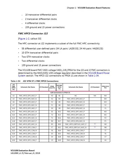
DS96F175C中文资料
- 格式:pdf
- 大小:241.45 KB
- 文档页数:10
Switching Characteristics
VCC = 5.0V, TA = 25˚C
Symbol
Parameter
tPLH
Propagation Delay Time,
Low to High Level Output
tPHL
Propagation Delay Time,
High to Low Level Output
元器件交易网
Switching Characteristics (Continued)
VCC = 5.0V, TA = 25˚C
Symbol
Parameter
Conditions
Min Typ Max Units
tLZ |tPLH– tPHL|
Output Disable Time from Low Level Pulse Width Distortion (SKEW)
元器件交易网
DS96F173M/DS96F175C/DS96F175M
COMMERCIAL
Absolute Maximum Ratings (Note 2)
Specifications for the 883 version of this product are listed separately.
VOL
Output Voltage LOW
IOZ
High-Impedance State Output
II
Line Input Current (Note 7)
IIH IIL RI IOS ICC ICCX
Enable Input Current HIGH Enable Input Current LOW Input Resistance Short Circuit Output Current Supply Current
Storage Temperature Range (TSTG) Lead Temperature
−65˚C to +175˚C
(Soldering, 60 sec.)
300˚C
Max. Package Power Dissipation (Note 1) at 25˚C
Ceramic DIP (J)
The DS96F173 and the DS96F175 have TRI-STATE® outputs and are optimized for balanced multipoint data bus transmission at rates up to 15 Mbps. The receivers feature high input impedance, input hysteresis for increased noise immunity, and input sensitivity of 200 mV over a common mode input voltage range of −7V to +12V. The receivers are therefore suitable for multipoint applications in noisy environments. The DS96F173 features an active high and active low Enable, common to all four receivers. The DS96F175 features separate active high Enables for each receiver pair.
compatible with SN75173/175 or the AM26LS32/MC3486
Logic Diagrams
DS96F175
DS009627-10 DS009627-11
Function Tables
(Each Receiver) DS96F173
Differential Inputs A–B
General Description
The DS96F173 and the DS96F175 are high speed quad differential line receivers designed to meet the EIA-485 standard. The DS96F173 and the DS96F175 offer improved performance due to the use of L-FAST bipolar technology. The use of LFAST technology allows the DS96F173 and DS96F175 to operate at higher speeds while minimizing power consumption.
Differential Inputs A–B
VID ≥ 0.2V VID ≤ −0.2V
X
Enable E H H L
Output Y H L Z
TRI-STATE® is a registered trademark of National Semiconductor Corporation.
© 2000 National Semiconductor Corporation DS009627
DS96F173M/DS96F175C/DS96F175M EIA-485/EIA-422 Quad Differential Receivers
元器件交易网
July 2000
DS96F173M/DS96F175C/DS96F175M EIA-485/EIA-422 Quad Differential Receivers
Features
n Meets EIA-485, EIA-422A, EIA-423A standards n Designed for multipoint bus applications n TRI-STATE outputs n Common mode input voltage range: −7V to +12V n Operates from single +5.0V supply n Reduced power consumption (ICC = 50 mA max) n Input sensitivity of ±200 mV over common mode range n Input hysteresis of 50 mV typical n High input impedance n Military temperature range available n Qualified for MIL STD 883C n Available to standard military drawings (SMD) n Available in DIP(J), LCC(E), and FlatPak (W) packages n DS96F173 and DS96F175 are lead and function
Over recommended supply voltage and operating temperature ranges, unless otherwise specified
Symbol
Parameter
Conditions
Min Typ Max Units
VTH
Differential-Input
VID ≥ 0.2V
VID ≤ −0.2V
X X
H = High Level L = Low Level Z = High Impedance (off) X = Don’t Care
Enable
E
E
H
X
X
L
H
X
X
L
L
X
X
H
Output Y H H L L Z Z
(Each Receiver) DS96F175
Note 3: Unless otherwise specified min/max limits apply across the 0˚C to +70˚C range for the DS96F175C. All typicals are given for VCC = 5V and TA = 25˚C. Note 4: All currents into the device pins are positive; all currents out of the device pins are negative. All voltages are reference to ground unless otherwise specified.
Operating Temperature (TA)
DS96F175C
0 25
Note 1: Derate package 10 mW/˚C above 25˚C.
Max
5.25 +12 |12| −400 11
70
Units
V V V µA mA
˚C
Electrical Characteristics (Notes 3, 4)
High Threshold Voltage
VO = VOH
0.2
V
VTL
Differential-Input (Note 5)
VO = VOL
Low Threshold Voltage
−0.2
V
VTH − VTL VIH VIL VIC VOH
Hysteresis (Note 6) Enable Input Voltage HIGH Enable Input Voltage LOW Enable Input Clamp Voltage Output Voltage HIGH