
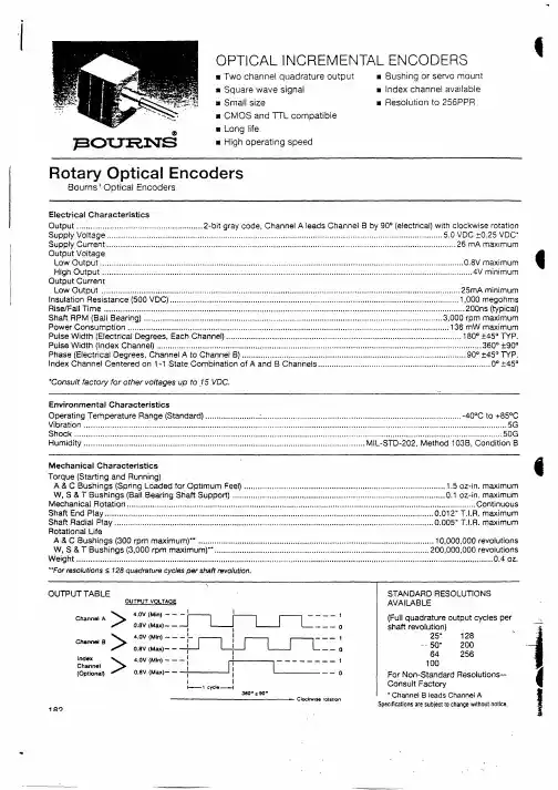
ENT2O-B20-R00050中文资料
- 格式:pdf
- 大小:216.72 KB
- 文档页数:2

READ AND SAVE THESE INSTRUCTIONSTechnical SpecificationsCheck the fan label to make sure it is the correct voltage.Operating voltage Diameter Weight Operating frequency120 VAC, 1 Φ52 in. (132 cm)11 lb (5 kg)60 Hz 220/240 VAC, 1 Φ52 in. (132 cm)11 lb (5 kg)50/60 HzTools Needed• Ladder• Wire Strippers• Phillips Screwdriver • Hex Key •WrenchesModels: L3127-X5, L3127-X6, FR127C-U1EXXScan or visit /support for online Haiku mobile app helpMounting Bracket Control Box Wiring Cover LED Diffuser Ring Mounting Ball & Hardware Lower Cover Trim Lower Cover Ring Extension Tube Motor Unit (3) Airfoils Remote Control Hardware PackPARTScdef2REV. H 8/27/2019 | © 2015 BIG ASS FANS | ALL RIGHTS RESERVEDHARDWAREHardware and tools needed for installation are packaged in the hardware pack. Hardware below shown at actual size.Mounting Hardware M8 Bolt M8 Washer M8 Nylock NutAirfoil Hardware(6) M5 Screws with Tooth WasherWiring Cover Hardware(4) M4 Socket Head Cap ScrewsLower Cover HardwareMounting Ball & HardwareSteel PinWedge4 mm Self-TappingScrewMounting Ball(2) Painted M3.5 Screws or3HAIKU® BY BIG ASS FANSPREPARE THE FAN SITEInstallation requires basic electrical knowledge. Contact a licensed electrician if you are uncomfortable performing electrical work!21Disconnect Power!Disconnect power to the fan location before wiring fan!If required by your local electrical code, a licensed electrician must install the fan.A means for disconnection must be incorporated in thefixed wiring in accordance with the wiring rules.If you are installing your fan to an outlet box, it must be suitable for fan support . If there is not an outlet box at the fan location,install one on a ceiling joist or beam.INSTALL THE MOUNTING BRACKETa4REV. H 8/27/2019 | © 2015 BIG ASS FANS | ALL RIGHTS RESERVED5HAIKU® BY BIG ASS FANSSecure the mounting bracket (a ) to the outlet box (b ) with the screws supplied with the outlet box (c ). Outlet Box Hardware:c. Screw (supplied with outlet box)STEP COMPLETED6REV. H 8/27/2019 | © 2015 BIG ASS FANS | ALL RIGHTS RESERVEDPREPARE THE AIRFOILS312SELECT LENS(BLACK FANS WITH LIGHTS)MATCH AIRFOIL STICKERS7HAIKU® BY BIG ASS FANS21Black fans with lights: For softer lighting, remove the white lens and install the smoky lens before attaching the airfoils.a. Twist to uninstall white lens.b. Twist smoky lens to lock in place.Make sure the stickers on the airfoils match the stickers on the fan hub.Rest the motor assembly (a ) on your lap. Moving clockwise, install each airfoil (b ) with the provided hardware. Tighten the screws to 2.5 N·m (22.1 in·lb). Do not use power tools to install the airfoils, and do not over-tighten the screws! Over-tightening the screws may cause the airfoils to warp and void your warranty.Airfoil Hardware:c. (6) M5 screws with tooth washerFans without lights: Position the motor cover (d ) over the motor, and then place both hands flat on the cover and turn it clockwise to lock it in place.DO NOT USE POWER TOOLS!STEP COMPLETED211Lower the extension tube (a) onto the motor shaft. Ensure the yellow arrow sticker on the extension tube is aligned with the sticker on the motor.CONNECT MOTOR WIRING AND SECURE EXTENSION TUBERemove the tie holding the wiring harnesses to the extension tube. Plug the two large wiring harnesses (a ) into the receptacles on the motor. Plug the small, male wiring harness (b ) into the female wiring harness from the motor shaft.Align the bolt holes on the extension tube with the holes on the motor shaft, and then secure the tube with the provided hardware and wrenches.Mounting Hardware:21Place the lower cover ring (a ) around the extension tube, resting it evenly on the motor. There should be a very small gap between the cover and the airfoils. Rotate the cover ring clockwise until it stops.Thread the wires through the opening in the lower cover trim (b ), and then slide the trim down the extension tube, resting it evenly on the cover ring.Align the screw holes on the trim with the motor screw holes, and then secure the trim in place with the provided screws (c ).213ARRANGE LED DIFFUSER RING, WIRING COVER, AND MOUNTING BALLcSlide the LED diffuser ring (a ), wiring cover (b ), and mounting ball (c ) down the extension tube (in that order), resting them on the fan hub.Do not seat the LED diffuser ring in the wiring cover at this step!ATTACH THE MOUNTING BALLSEAT MOUNTING BALL INSTALL WEDGEInsert the steel pin (a ) into the hole at the top of the extension tube, and then slide the mounting ball upward, seating the steel pin in the inner slots of the ball.Mounting Ball Hardware:a. Steel pinInsert the wedge (b ) into the mounting ball as shown, and then secure the wedge with the screw (c ). Tighten the screw enough to prevent movement between the mounting ball and extension tube. Do not over-tighten 21Raise the fan to the mounting bracket. Align the slot in the mounting ball with the rib in the mounting bracket, insert the mounting ball, and let the fan hang freely.Gently twist the extension tube to ensure the mounting ball is properly seated and will not move during fan operation.STEP COMPLETED21INSTALL THE UPPER EARTH/GROUND WIRERoute the ground wire from the extension tube (a) to the outside of the mounting bracket. Secure the ground wire terminal (b) to the mounting bracket with the screw (c).STEP COMPLETEDMake sure power is disconnected before wiring the fan!Do not connect the fan to a damaged power source! Do not attempt to resolve electrical failures on your own. Consult a qualified electrician if uncertain of the electrical installation of this fan.Make the electrical connections by securing the supply power wires to the loose ends of the wiring harness (a ) with the provided wire nuts.Test the connection by lightly tugging on the wires.Tuck the power wiring and wire nuts into the outlet box.321Insert the control box (a ) into the mounting bracket as illustrated. Be careful not to pinch the wires between the mounting bracket and control box!Snap the LED indicator (b ) into the gap in the mounting bracket. Make sure it is securely seated.21CONNECT THE CONTROL BOX2CONNECT WIRING HARNESSES29HAIKU® BY BIG ASS FANS Connect the wiring harness from the control box (a ) to the harness from the junction box (b ).Peel the backing off the double-sided tape (c) on the mounting bracket, and then affix the harnesses to the tape.Connect the wiring harnesses from the extension tube (d ) to the corresponding receptacles (e ) on the control box.12INSTALL THE WIRING COVER30REV. H 8/27/2019 | © 2015 BIG ASS FANS | ALL RIGHTS RESERVED31HAIKU® BY BIG ASS FANS Slide the wiring cover (a ) up the extension tube, aligning the yellow arrow stickers so that the top of the wiring cover sits flush with the mounting bracket. Make sure the LED indicator receptacle shows through the opening in the cover (b ).Make sure all wiring is tucked into the wiring cover, and then secure the cover with the provided screws (c ).Wiring Cover Hardware:c. (4) M4 socket head cap screwsSlide the LED diffuser ring (d ) up the extension tube and plugthe connector into the LED indicator receptacle through theopening (b ) in the wiring cover.Make sure the tabs on the diffuser ring are securely snappedin place.12STEP COMPLETED332REV. H 8/27/2019 | © 2015 BIG ASS FANS | ALL RIGHTS RESERVEDTEST THE FANDo not expose the remote control to rain or water.Turn on power to the fan location and test functionality using the remote. Turn on the fan and test speed and light brightness*.*Applies only to fans with lightsTurns fan on or off.Sets fan timer length of up to eight hours.Each press extends timer by one hour.Turns light on or off.Clears active fan timer.Increases fan speed/light brightness.Varies fan speed to simulate a naturalbreeze.Decreases fan speed/light brightness.Automatically adjusts your fan speedovernight to keep you comfortable whileyou sleep.For operation, maintenance, and troubleshootinginformation, visit /supportUnited States 2348 Innovation DriveLexington, KY 40511+1 855 694 2458© 2015 Big Ass FansThe information contained in this document is subject to change without notice. May be protected by one or more patents listed at /patentsHaiku is a trademark of Delta T LLC, registered in the U.S. and/or other countries.For warranty information, visit /product-warrantiesCanada 2180 Winston Park Drive Oakville, Ontario L6H 5W1Canada1 844-924-4277Mexico CEBSA (Corporación Eléctrica del Bravo SA de CV)Avenida Ind. Rio San Juan Lote 3-A Parque Industrial del Norte Reynosa, Tamps C.P. 88736/+52 1 899 925 6398。
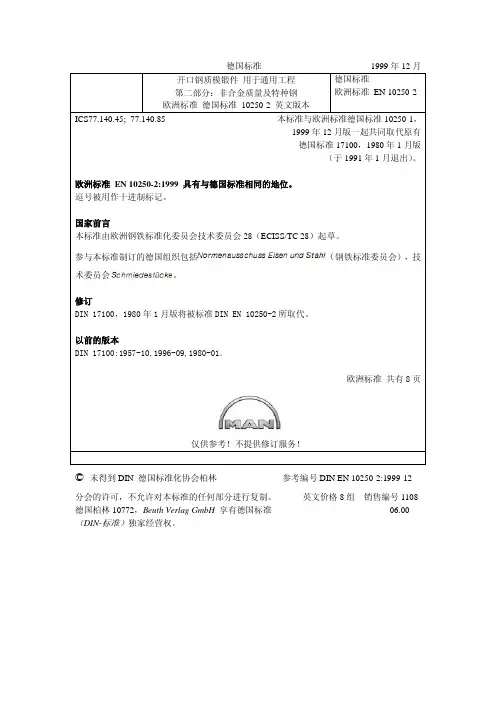
德国标准 1999年12月(术委员会© 未得到DIN 德国标准化协会柏林参考编号DIN EN 10250-2:1999-12分会的许可,不允许对本标准的任何部分进行复制。
英文价格8组销售编号1108 德国柏林10772,Beuth Verlag GmbH 享有德国标准 06.00 (DIN-标准)独家经营权。
欧洲标准 EN 10250-21999年10月ICS 77.140.45;ICS 77.140.85英文版本用于通用工程的开口钢质模锻件第二部分:非合金质量及特种钢本标准于1999年9月9日获得了欧洲标准化委员会的批准。
欧洲标准化委员会的成员必须遵守欧洲标准化委员会/欧洲电工标准化委员会的内部规定。
欧洲标准化委员会/欧洲电工标准化委员会规定了生成本欧洲标准的条件,并规定了没有任何变化的国家标准的状态。
与这些国家标准相关的最新列表及参考书目可通过向重要秘书处或任何一个欧洲标准化委员会成员申请获得。
本欧洲标准存在三种官方版本(英文、法文、德文)。
由欧洲标准化委员会成员组织翻译成其自己语言,并告知了秘书处的任何其他语言版本的标准,与本官方版本具有同等地位。
欧洲标准化委员会成员是以下国家标准的主体,包括奥地利、比利时、捷克共和国、丹麦、芬兰、法国、德国、希腊、冰岛、爱尔兰、意大利、卢森堡、荷兰、挪威、葡萄牙、西班牙、瑞典、瑞士以及英国。
CEN欧洲标准化委员会中央秘书处:rue de Stassart 36, B-1050 布鲁塞尔© 1999.欧洲标准化委员会-全世界参考编号EN 10250-2:1999E欧洲标准化委员会的国家成员保留任何形式及方式的开发权第二页EN 10250-2:1999目录页码前言 21 范围 32 参考标准 33 化学成分 34 热处理 45 机械性能 5附录A (信息功能)热处理 8前言本欧洲标准由欧洲钢铁标准化委员会(ECISS/TC28)“钢锻件”技术委员会起草。


BIOPOWER 中文使用说明书.经销商制造商仅限 RxREF 1601147-001REF 1303393-001REF 1601008-001REF 1600692-001REF 1601009-001REF 1600631-001REF 1500984-005REF 1301575-001REF 1502329-002REF 1307727-010选配件REF 1601008-001REF 1600692-001REF 1600598-001REF 1600785-001REF 1600786-001 REF 1600052-001REF 1303393-001 REF 1601009-001REF 1600631-001REF 1301575-001REF 1502329-010REF 1307727-010REF 1307312-010REF 1500984-010REF 1501738-010REF 1501635-010REF 1501621-010 REF 1307031-001Bien-Air Dental 参考目录1符号 (2)1.1BIOPOWER主机符号释义 (2)1.2BIOPOWER配件符号释义 (2)2产品简介、用途与表示法 (3)2.1产品简介 (3)2.2预期用途 (3)2.3预期患者人群 (3)2.4预期用户 (3)2.5预期医疗条件 (3)2.6患者禁忌症与警告 (3)2.7事故情形 (3)2.8表示法和章节链接 (3)3警告与使用预防措施 (4)3.1基本信息 (4)3.2警告 (4)4描述 (5)4.1BIOPOWER 系统概览 (5)4.2提供的套装 (6)4.3选配件 (6)4.4技术参数 (6)4.5性能 (7)4.6环境保护和处置信息 (7)4.7电磁兼容性 (技术描述) (7)4.7.1使用预防措施 (7)4.7.2电磁兼容性警告 (7)4.7.3电磁兼容性 – 辐射和抗干扰能力 (8)5安装 (10)5.1 安装 BIOPOWER 系统 (11)5.2开/关过程 (11)6界面总览 (12)6.1BIOPOWER模式 (12)6.2旋钮功能概览 (12)6.3声音警告 (13)7治疗 (14)7.1治疗画面描述 (14)7.2执行治疗:步骤P1和P2 (14)7.3执行治疗:步骤P3、P4和P5 (15)8设置 (16)8.1MX-i LED第3代微型电动马达速度 (16)8.2MX-i LED第3代微型电动马达扭矩 (16)8.3MX-i LED第3代微型电动马达旋转方向 (16)8.4灌注流量 (17)8.5弯手机转速比 (17)9特殊模式 (18)10 错误和故障处理列表 (20)10.1安全警告 (运行中) (20)10.2设备运行错误 (21)11 维护 (22)11.1维修 (22)11.2清洁与灭菌 (22)11.3重要信息 (23)11.4更换保险丝 (23)12 保修条款 (24)1.1BIOPOWER 主机符号释义1.2BIOPOWER 配件符号释义保险丝。