LD 中文
- 格式:pdf
- 大小:423.01 KB
- 文档页数:6

244LD型智能浮筒液位(界位)变送器辽制目录1. 概述.............................................................. - 0 -2. 产品特色............................................................ - 1 -3. 主要技术参数........................................................ - 2 -4. 变送器选型表........................................................ - 3 -5. 测量原理............................................................ - 4 -6. 安装与电气连接...................................................... - 5 -7. 运行调试............................................................ - 7 -8. 现场显示............................................................ - 8 -9. 维护、修理.......................................................... - 8 -10. 安全要求........................................................... - 9 -11. 变送器外形图及安装尺寸............................................ - 10 -12. 变送器的供电...................................................... - 11 -13. 订购仪表注意事项.................................................. - 13 -14. 包装、标志、运输及贮存............................................ - 13 -15. 计算公式及计算方法................................................ - 14 -16.故障分析与排除..................................................... - 15 -17. 变送器的调试...................................................... - 14 -1.概述244LD型智能浮筒液(界)位变送器在工况下可以实现持续的液体液位、界位及密度的测量。

元器件交易网LITE MAX LD1041Sunlight Readable 10.4" LCD Display(1st Edition 3/26/2004 )All information is subject to change without notice.LITE MAX Electronics Inc.4F, No.131-3, Lane235, Bau-chiau Rd.,Shin-dian City, Taipei County, Taiwan R.O.C.Tel : 886-2-8919-1858Fax: 886-2-8919-1300Homepage: 元器件交易网Contents:Introduction and overview……..........................................P3A. Physical specifications…….......................................... P4B. Electrical specifications…........................................... P51. Pin assignment….......................................................P52. Absolute maximum ratings…...............................................P63. Electrical characteristics….................................................P7a. Typical operating conditions…..........................................P7b. Display color v.s. input data signals…...........................……...P8c. Input signal timing…................................................P9d. Display position…...................................................P10e. Backlight driv ing conditions…......................................P11C. Optical specifications…................................................. P12D. Reliability test items….................................................... P14E. Display quality…....................................................... P15F. Handling precaution …................................................ P15Appendix:Fig.1 LCM outline dimensions…...........................…...............P16Fig.2 Timing chart.............................................................P17Li2701 Inverter .............................................................P182020 A/D Board…...........................................................P24INTRODUCTION AND OVERVIEWThis is a product specification that specifies form, fit, and function of the 10.4” TFT LCD monitor and its options. The L D1041 products are a family of high bright LCD monitors intended for use in a variety ofindustrial and commercial applications. Some of these applications include Car TV, Kiosk, Control Panel,Fish Finder, Marine, POI, Teketing, Aviation, Advertising, Gas Pumps, Signage... The LCD panel forL D1041 has a particularly fast response time of 35ms and consequently very well suited for video applications.The L D1041 is a 10.4” active matrix TFT LCD with a native resolution of 800X600 (SVGA). It has a typical luminance of 1500 nits with a +12VDC input. The video interface is through a standard 15 pin analog input with an integrated On-Screen Display (OSD).OUTLINESTRUCTURE AND PRINCIPLEL D1041 module is composed of the driver LSIs for driving the TFT (Thin Film Transistor) array with anamorphous silicon thin film transistor liquid crystal display (a-Si TFT LCD) panel structure and a backlight.The a-Si TFT LCD panel structure is injected liquid crystal material into the narrow gap between a TFT array glass substrate and a color filter glass substrate.RGB (Red, Green, and Blue) data signals from a source system are modulated into a form suitable for active matrix addressing by the onboard signal processor and sent to the driver LSIs which in turn address theindividual TFT cells.Working as an electro-optical switch, each TFT cell regulates transmitted light from the backlight assembly when worked by the data source. Color images are created by regulating the amount of transmitted light through the array of red, green and blue dots.APPLICATIONSE Car TV, Kiosk, Control Panel, Fish Finder, Marine, POI, Teketing, Aviation, Advertising, Gas Pumps, Signage... FEATURES¡E wide viewing angleE F ast response timeE H igh Contrast Ratio¡E L VDS¡E W ide color gamutE V ery hight brightness¡E S unlight ReadableA. Physical specificationsNO. Item Specification Remark1 Display resolution (pixel) 800(H)×600(V)2 Active area (mm) 211.2(H)×158.4(V)3 Screen size (inch) 10.4(Diagonal)4 Pixel pitch (mm) 0.264(H)×0.264(V)5 Color configuration R. G. B. Vertical stripe6 Overall dimension (mm) 340(W)×228(H)×54.2(D) (typ.) Note 17 Weight (kg) 3.15 ±10Note 1: Refer to Fig. 1. & 2.B. Electrical specifications1. Pin assignment(1) Input signal interfacePin no Symbol Function Etc.1 V CC+3.3 V power supply2 V CC+3.3 V power supply3 GND Ground4 GND Ground5 RxIN0-6 RxIN0+LVDS receiver signal channel 07 GND Ground8 RxIN1-9 RxIN1+LVDS receiver signal channel 110 GND Ground11 RxIN2-12 RxIN2+LVDS receiver signal channel 213 GND Ground14 CKIN-15 CKIN+LVDS receiver signal clock16 GND Ground17 NC No Connection18 NC No Connection19 GND Ground20 GND GroundCN1 (20P) connector: HRS DF 19K-20P-1H or compatible(2) LVDS transmitter/receiver signal mappingSymbol FunctionTxIN0 R0 Red data (LSB)TxIN1 R1 Red dataTxIN2 R2 Red dataTxIN3 R3 Red dataTxIN4 R4 Red dataTxIN5 R5 Red data (MSB)6 bit red display dataTxIN6 G0 Green data (LSB)TxIN7 G1 Green dataTxIN8 G2 Green dataTxIN9 G3 Green dataTxIN10 G4 Green dataTxIN11 G5 Green data (MSB)6 bit green display dataTxIN12 B0 Blue data (LSB)TxIN13 B1 Blue dataTxIN14 B2 Blue dataTxIN15 B3 Blue dataTxIN16 B4 Blue dataTxIN17 B5 Blue data (MSB)6 bits blue display dataTxIN18 Hs Horizontal sync.TxIN19 Vs Vertical sync.TxIN20 DE Data enableTxCLKIN CLK Clock Dot clock2. Absolute maximum ratings (GND = 0 V)Values Parameter SymbolMin. Max. UnitRemarkPower voltage V CC-0.3 4 V DC At 25℃Input signal voltage V LH-0.3 V CC+0.3 V DC At 25℃Operating temperature T op 0 +50 ℃Note 1Storage temperature T ST-20 +60 ℃Note 1 Note 1:The relative humidity must not exceed 90% non-condensing at temperatures of 40℃or less. At temperatures greater than 40℃, the wet bulb temperature must not exceed 39℃. When operate at low temperatures, the brightness of CCFL will drop and the lifetime of CCFL will be reduced.Note 2:The unit should not be exposed to corrosive chemicals.3. Electrical characteristicsa. Typical operating conditionsItemSymbol Min. Typ. Max. Unit RemarkInput voltage V CC 3.0 3.3 3.6 V I A 243.7 242 245.2 mArms Current consumption I B 255.4 252.1 253.5 mArms Note 1 Power supply voltageInrush currentI RUSH - - 1500 mApeakNote 2Low voltage V IL 0 - 0.3 V CC Internal logicHigh voltageV IH 0.7V CC - V CC Power ripple voltageV RP--100mVp-pNote 1:Effective value (mArms) at V CC = 3.3 V/25℃.Note 2: Refer to the following power-on condition.Sequence of Power-on/off and signal-on/offPowerInput signalApply the lamp voltage within the LCD operating range. When the backlight turns on before the LCD operation or the LCD turns off before the backlight turns off, the display may momentarily become abnormal. I White Black 50ms ≦T1<80msec0≦T2<70msec 300msec ≦T3 300msec ≦T4 T5≦10msec 90%10%T on=470μs ±10%VccT4T2T1T5 T3Horizontal stripe lineI B Black ( 0 ) 63 Gray ( 15 )The above on/off sequence should be applied to avoid abnormal function in the display.In case of handling:Make sure to turn off the power when you plug the cable into the input connector or pull the cable out of the connector.b. Display color v.s. input data signalscombining the 18-bit data signals(R, G, B), the 262,144 colors can be achieved on thedisplay.c. Input signal timingTiming diagrams of input signal are shown in Fig 2.(1) Timing characteristics of input signals(a) DE modeItem Symbol Min. Typ. Max. Unit Remark Clock frequency Fck 38 40 48 MHzHorizontal blanking Thb1 50 256 500 ClkVertical blanking Tvb1 10 28 150 Th(b) HV modeItem Symbol Min. Typ. Max. Unit Remark Clock frequency Fck 38 40 48 MHzHsync period Th 850 1056 1300 ClkHsync pulse width Thw 10 128 - ClkHsync front porch Thf 15 40 - ClkHsync back porch Thb 10 88 - ClkHsync blanking Thb1 50 256 500 ClkVsync period Tv 610 628 750 ThVsync pulse width Tvw 1 4 - ThVsync front porch Tvf 0 1 - ThVsync blanking Tvb1 10 28 150 ThHsync/Vsync phase shift Tvpd 2 320 - ClkItem Symbol Value Unit Description Horizontal display start The 218 Clk After falling edge of Hsync, counting218clk, then getting valid data from 219thclk’s data.Vertical display start Tve 25 Th After falling edge of Vsync, counting 25th,then getting 26th Th’s data.(2) The timing condition of LVDSItemSymbol Min. Typ. Max. Unit The differential level |VID | 0.1 - 0.6 V The common mode input voltageVIC - V The input setup time tsu1 500 - - ps The input hold timeth1500--psd. Display positionD( 1,1 ) D( 2,1 ) …… D( X,1 ) …… D( 799,1 ) D( 800,1 ) D( 1,2 )D( 2,2 )…… D( X,2 )…… D( 799,2 )D( 800,2 ). . . …… . . . …… . . . . . . D( 1,Y )D( 2,Y )…… D( X,Y )…… D( 799,Y )D( 800,Y ). . . …… . . . …… . . .. . .D( 1,599 ) D( 2,599 ) …… D( X,599 ) …… D( 799,599) D( 800,599 ) D( 1,600 )D( 2,600 )……D( X,600 )……D( 799,600) D( 800,600)2.4-︱VID ︱ 2 ︱VID ︱ 2 Ri, Gi, Bi i=0~5DE7×CLKth1tsu1 V IA MIA P -V IA M--e. Backlight driving conditionsParameter Symbol Min. Typ. Max. Unit Remark Lamp voltage V L - 420 - Vrms Note 1 Lamp current I L 33 36 39 mArms Note 1 Power consumption P L - 30.0 - W Note 2 - - - T=0℃ Lamp starting voltage V S - 1700 - Vrms T=25℃ Frequency F L 50 55 60 KH Z Note 3 Lamp life timeL L-50,000-HrNote 1, 4Note 1: T= 25℃, I L = 6mA/Lamp (Total 6 lamps)Note 2: Inverter should be designed with the characteristic of lamp. When you are designingthe inverter, the output voltage of the inverter should comply with the following conditions.(1) The area under the positive and negative cycles of the waveform of the lampcurrent and lamp voltage should be area symmetric (the symmetric ratio should be larger than 90%).(2) There should not be any spikes in the waveform. (3) The waveform should be sine wave as possible.(4) Lamp current should not exceed the maximum value within the operatingTemperature (It is prohibited to over the maximum lamp current even if operated in The non-guaranteed temperature). When lamp current over the maximum value for a long time, it may cause fire. Therefore, it is recommend that the inverter should have the current limited circuit.Note 3: Lamp frequency may produce interference with horizontal synchronous frequencyand this may cause line flow on the display. Therefore lamp frequency shall be detached from the horizontal synchronous frequency and its harmonics as far as possible in order to avoid interference.Note 4: Brightness (I L =6mA/Lamp) to be decrease to the 50% of the initial value.Note 5:CN2~4 connector (backlight): JST BHR-03VS-1Pin no. Symbol FunctionRemark 1 H CCFL power supply (H.V.) Cable color: Pink 2HCCFL power supply (H.V.)Cable color: PinkMating connector: JST SM03(4.0)B-BHS-1-TBCN5 connector (backlight): JST BHSR-02VS-1Pin no. SymbolFunctionRemark 1 L CCFL power supply (GND) Cable color: White 2LCCFL power supply (GND)Cable color: PinkMating connector: JST SM02B-BHSS-1-TBC. Optical specifications (Note 1, Note 2)Specification ItemSymbol Condition Min. T yp. Max. UnitRemarkResponse time Rising time Falling time Tr Tf θ=0° - - 10 25 20 30 ms Note 4 Contrast ratio CR θ=0°400 500 -Note 3,5Viewing angleT op Bottom Left RightCR ≧10- - - - 40 60 60 60 - - - - deg. Note 3,6BrightnessY L θ=0° 1200 1500 - nit Note 3,7,8,9 Wx 0.290 0.320 0.350 Wy 0.300 0.330 0.360 Rx TBD TBD TBD Ry TBD TBD TBD Gx TBD TBD TBD Gy TBD TBD TBD Bx TBD TBD TBD Color chromaticity(CIE)Byθ=0°TBDTBD TBDNote 3,8,9White uniformity δW--1.3Note 3,9,10Note 1: Ambient temperature = 25℃.Note 2: To be measured in dark room after backlight warm up 30 minutes.Note 3: To be measured with a viewing cone of 1°by T opcon luminance meter BM-5A. Note 4: Definition of response time:The output signals of BM-7 are measured when the input signals are changed from “Black ” to “White ” (falling time) and from “White ” to “Black ” (rising time), respectively. The response time means the interval between the 10% and 90% of amplitudes. ReferNote 5. Definition of contrast ratio:Contrast ratio is calculated with the following formula.Note 6: Definition of viewing angle:Note 7: Definition of the 5 points (from A to E) on panel, refer to figure as belowNote 8: Definition of brightness: To measure at center point of the screen (C)(After light up 20 minutes)Note 9: Driving conditions for CCFL: I L =6 mA, 55KHz FrequencyNote 10: Definition of white uniformity:Contrast ratio (CR)=Luminance on the white raster Luminance on the black rasterθD. Reliability test items (Tentative)Test tem Test Condition Remark High temperature storage 60℃, 240Hrs Note 1, 2, 3 Low temperature storage -20℃, 240Hrs Note 1, 2, 3High temperature & high humidity operation 40℃, 90%RH, 240Hrs(No condensation)Note 1, 2, 3High temperature operation 50℃, 240Hrs Note 1, 2, 3 Low temperature operation 0℃, 240Hrs Note 1, 2, 3Electrostatic discharge (non-operation) 150 pF,150Ω,10kV,1 second, 9 positionon the panel, 10 times each placeNote 3Vibration (non-operation) 1.5G, 10H Z ~ 200H Z ~ 10H Z30 minutes for each Axis (X, Y, Z)Note 1, 2, 3Mechanical shock (non-operation) 50G/20ms, ±X, ±Y, ±Zhalf-Sin, one timeNote 1, 2, 3Thermal shock (non-operation) 1. -20℃±3℃…30minutes60℃±3℃…30minutes2. 100 cycles3. T emperature transition time within 5minutesNote 1, 2, 3Note 1: Evaluation should be tested after storage at room temperature for one hour.Note 2: There should be no change which might affect the practical display function when the display quality test is conducted under normal operating condition.Note 3: Judgement: 1. Function OK2. No serious image quality degradationE. Display qualityThe display quality of the color TFT-LCD module should be in compliance with the Litemax’s OQC inspection standard.F. Handling precautionThe Handling of the TFT-LCD should be in compliance with the Litemax’s handling principle standard.F i g .2 T i m i n g c h a r t1. ENVIRONMENT CHARACTERISTICS:1-1. All Conditions are at 25¢J Ambient unless otherwi se specified1-2.Operating Temperature 0¢J~~---+55¢J1-3. Storage Temperature -25¢J------+70¢J1-4. Humidity Operating 95¢M1-5. Humidity Storage 95¢M2. CONNECTOR PIN ASSIGNMENT:Input : CN4 Output : CN1,CN2,CN3Model : 2001J-06-RT(90¢X) Model : SM02(8.0)B-BHS-1-TBSupplier : ORICH Supplier : JSTPin Symbol Pin Symbol1 Vin 1 HV2 Vin 2 HV3 ON/OFF Output : CN54 Brt ADJ(0.0V~5.0V) Model : SM02B-BHSS-1-TB5 GND Supplier : JST6 GND 1 RETURN2 RETURNTEST INSTRUMENT:1. OSCILLOSCOPE : TDS380 DIGITAL REAL-TIME OSCILLOSCOPE2. HIGH VOLTAGE PROBE : TEKTRONIX P5100 (1:100)3. CURRENT PROBE AMPLIFIER : TEKTRONIX AM503B4. CURRENT PROBE : TEKTRONIX A63025. DC POWER SUPPLY : GW GPC-3060D6. MULTIMETER : FLUKE 45 DUAL DISPLAY3. SCOPE3-1 This document defines the requirements for the CCFL inverter of the TFT-LCD panel.This product is compatible with 10” Six Lamp Panel.4. ELECTRICAL CHARACTERISTICS4-1 INPUT Brt. ADJ=0.0V.PARAMETER SYMBOL MIN. NOM. MAX. UNIT REMARKINPUT VOLTAGE Vin 10.8 12.0 13.2 VINPUT CURRENT Iin 1450 1770 2010 mA RL=70K£[*6 Vin = 12VFL(1,2,3) 46 51 56LAMP FREQUENCYFL(4,5,6) 46 51 56KHz Vrmt=0.0VVs(1,2,3) ---- 1500 ----OPEN OUTPUT VOLTAGEVs(4,5,6) ---- 1500 ----Vrms Vin=12V.PARAMETER SYMBOL MIN. NOM. MAX. UNIT REMARK INPUT VOLTAGE Vin 10.8 12.0 13.2 VINPUT CURRENT Iin 640 830 1050 mA RL=70K£[*6 Vin = 12VFL(1,2,3) 46 51 56LAMP FREQUENCYFL(4,5,6) 46 51 56KHz Vrmt=5.0VIout(1,2,3) 4.0 4.5 5.0OUTPUT CURRENTIout(4,5,6) 4.0 4.5 5.0mA Vrmt=5.0VVout 1,2,3 ---- 310 ----LAMP VOLTAGEVout 4,5,6 ---- 310 ----Vrms Vrmt=5.0V NOTE: All Conditions are at 25¢J Ambient unless otherwise specified! "#$ % & ' %( & & % )*+,$) ,"#$ -. / 0. 12! ! ! " # !$ % & ' ( ) % )* )*+ )* + ) ,-,.$/% 0 1 2% !2 3" ! ! ( ) , %(% 4 / 0 5 6 0 ! !! 6 17 0 8 & " !) ! ) ! % & !) 9 / ) 3 ", !!DC12VDC/DCAnalog RGB HS&VSDC/DC2.5V5VRT2010ROMRT2020ProgramVideo24.576MHzSPanelPowerSelect3.3VRGBDEN,VSDigitalHS,DCLKPanelInterfaceTTLKey6 BitLVDS8 Bitx1xLVDS1PanelInterfaceLVDS 5VDC/DCDecode$ ! 2 ! .2 ! - ! :; 2/(4 2:1 , 2:2 /2: 12: <41,24:=; $) 2/(4 2:1 , $) ;)$>(, <41,24:=$: ) 2:1 , / 912: -( ).($: 147( $4::($,4 ?9$:@ ) /24 2: $4::($,4 @?; * @ 1()>( $4::($,4 1AB ? %%* 12:* 6; 2: ( ,( $4::($,4 1AB ? %%* 12:*C; >( 4) / $4::($,4 1AB ? %%* 12:*C; .$/ -4 . / <12: A()/= 1AB ? %%* 5 912:* 6 D; @ , 4) / $4::($,4 1AB ? %%*612:* 6 D*<41,24:=1AB ?9%%* 93@ 12:*C D<41,24:= ;9*; ,,. 4 ,1 , -1$$4::($,4; *; @B E $ !12: - ! :2 :).:/; B2 " $ !12: - ! :$$:/@ )$>.2 A, 147( 4:34--2 A,:( $4:, 4.; B> & $ !12: - ! :9 / $$2 2:1 ,@ (: <) ,4= >((:,( >(9 (.< 2 A,= >((.<.(-,= >(F )$,2 ( < ((:= .(/6 ,):/ < (/= .(/C 147( >(:/; B.$/ - . / $ !12: - ! :1):(. $$1):(. $$@ 1):(. $$/ :/9 / :// :/F / :/6 / :/C / :/+42:@G+42:+4$>2:G@ +4$>2:+42: G9 +42:+42: GF +42:6 +42: GC +42:+(2:@G+(2:@+($>2:G@ +($>2:+(2: G9 +(2:+(2: GF +(2:6 +(2: GC +(2:@ / :/; @B, $ !12: - ! :9 / $$$$@ $ $.$ /)9 2- 2/(4:/F 2- ) /246 2- ) /24; *; B $)3 212: - ! :2: ;$2: ;@ :/ ;2: ;9 :/ ;$: B ) 212: - ! :@:$9 / :/) :/F ) :/6 ) :/C :$/ :/:$//$ /)@ A 2:2:9 //$ $.$: B1 ' $ !12: - ! ::/ ;:/ ;@ $$$:@B) 2 $ !12: - ! :2-H) /24*2: 1()>( *,/)F C .:/@ :/2-H) /24*2:. 1()>( *,/)F C .9 :/;9B,,. 4 -1$ $ !12: - ! ::4 - :$,24::4 - :$,24:@ :$ - :$,24:1):(. $$9 1):(. $$/) (/F /) (/6 /) (/C /) (/@://) (//) (/9@ /) (//) (/F9 ://) :4F /) :6 /) :C /) :@://) :/) :9@ /) :/) :F9 :/F /) .6 /) .C /) . @@ :/@ /) .@ /) . 9@@ /) .@ /) . F@9 :/@ :4 - :$,24:@F :/@6 /A@C ://://(:@ ://$.>9 :/; B,,. 4 -1$ $ !12: - ! : / (// (/@ / (// (/@9 :// (/F / (/96 / (/C / (/F:// :4/ :@ / :/ :@9 :// :F / :96 / :C / :F:// ./ ./ . @ 9 :/ / .F / . 96 / .C / . F @ :/! " #。


ld的多种含义
1. LD作为缩写,可以指代学习障碍(Learning Disability),特指个体在语言、阅读、写作、数学、记忆等方面存在困难的情况。
2. LD也可以代表逻辑设计(Logic Design),是指在数字电路系统中使用的逻辑元器件和线路的设计。
3. LD还可以是路德会(Lutheran Church),是基督教中的一支教派,以德国宗教改革者马丁·路德为名。
4. LD也可以指导学教育(Leadership and Development),是指通过培训和发展个人的潜能和领导能力来推动组织的发展。
5. LD还有可能指代低密度(Low Density),特指在计算机存储器中,存储单元的密度相对较低。
需要根据上下文进一步了解具体含义。
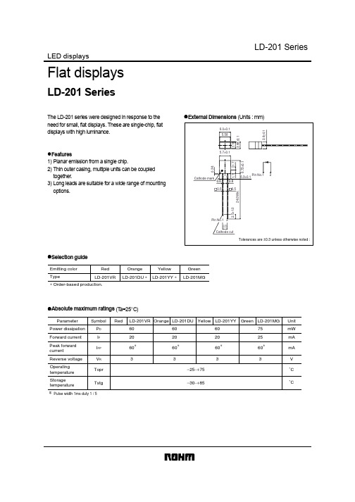
绿色模式PWM控制器与高压启动电路概述LD7575是一个带有良好的省电操作的电流模式PWM控制器。
它具有一个高电压的电流源直接从大容量电容器提供启动电流,并进一步提供了无损的启动电路。
它的集成功能如电流检测的前沿消隐,内部斜率补偿,和小组件,为使用者提供了高效率、最少的外部元件数量和AC / DC电源应用低成本的解决方案。
此外,嵌入过电压保护,过负荷保护和特殊的绿色模式控制为用户能够更容易地设计一个高性能的电源电路提供了解决方案。
LD7575有SOP- 8和DIP – 8两种封装方式。
特点·高电压(500V)启动电路·电流模式控制·非听觉噪声的绿色模式控制·UVLO(欠压锁定)·CS引脚的LEB(前沿消隐)·可编程开关频率·内部斜率补偿·Vcc的 OVP(过压保护)·OLP(过载保护)·500毫安驱动能力应用·开关AC / DC适配器和电池充电器·Open Frame Switching Power Supply(打开帧开关电源?/开放式框架开关电源?)·液晶显示器/电视电源典型应用引脚配置SOP-8和DIP-8(顶视图)订购信息LD7575是符合RoHS标准。
部件号封装顶部标记送货LD7575 PS SOP-8LD7575PS2500/磁带和卷轴LD7575 PN DIP-8LD7575PN3600 /管/箱引脚说明引脚名称功能1RT此引脚是控制开关频率。
通过一个电阻连接到地设置开关频率2COMP 电压反馈引脚(与UC384X的COMP引脚相同),通过连接的光电耦合器来闭合控制回路,实现调控。
3CS电流检测引脚,连接检测MOSFET的电流4GND接地引脚5OUT栅极驱动输出,以驱动外部MOSFET6VCC电源电压引脚7NC未连接引脚8 HV该管脚连接到大电容的正极,从而为控制器提供启动电流。
五年级上册英语第一单元单词一、old读音:[əʊld]中文释义:年老的;旧的。
解析:可以用来形容人年纪大,如“an old man”(一位老人);也可以形容物品旧了,如“an old book”(一本旧书)。
二、young读音:[jʌŋ]中文释义:年轻的;幼小的。
解析:与“old”相对,形容人年龄小或者动物幼小时可以用这个词,如“a young girl”(一个年轻的女孩)。
三、funny读音:[ˈfʌni]中文释义:滑稽的;可笑的。
解析:通常用来形容人或事物很有趣、能引人发笑,如“a funny story”(一个有趣的故事)。
四、kind读音:[kaɪnd]中文释义:和蔼的;亲切的;宽容的。
解析:可以形容人的性格温和善良,如“a kind teacher”(一位和蔼的老师)。
五、strict读音:[strɪkt]中文释义:严格的;严厉的。
解析:常用来形容老师、家长等对人要求严格,如“a strict father”(一位严厉的父亲)。
六、polite读音:[pəˈlaɪt]中文释义:有礼貌的;客气的。
解析:形容人的行为举止有礼貌,如“a polite student”(一个有礼貌的学生)。
七、hard-working读音:[ˌhɑːd ˈwɜːkɪŋ]中文释义:努力工作的;勤奋的。
解析:用来形容人工作努力或者学习勤奋,如“He is a hard-working student.”(他是一个勤奋的学生。
)八、helpful读音:[ˈhelpfl]中文释义:有用的;愿意帮忙的。
解析:表示某人或某物能够提供帮助,如“She is a helpful girl.”(她是一个乐于助人的女孩。
)九、clever读音:[ˈklevə(r)]中文释义:聪明的;机灵的。
解析:形容人头脑聪明、反应敏捷,如“He is a clever boy.”(他是一个聪明的男孩。
)十、shy读音:[ʃaɪ]中文释义:羞怯的;腼腆的;怕生的。
ld是什么材料LD是什么材料。
LD材料是一种广泛应用于工业和民用领域的新型材料,它具有轻质、高强度、耐腐蚀、耐磨损等优良性能。
LD材料的全称是“Low Density”,意为低密度材料,通常指的是密度低于1g/cm³的材料。
LD材料的应用范围非常广泛,下面我们将从材料特性、应用领域和未来发展趋势三个方面来详细介绍LD材料。
首先,LD材料的特性是其能够在保持较低密度的同时具有较高的强度。
这使得LD材料在航空航天、汽车、轻型工具等领域有着广泛的应用前景。
另外,LD材料还具有良好的耐腐蚀性和耐磨损性,能够在恶劣环境下长时间稳定使用,因此在海洋工程、化工设备等领域也有着重要的应用价值。
其次,LD材料的应用领域非常广泛。
在航空航天领域,LD材料可以用于制造飞机机身、发动机零部件等,能够大幅减轻飞机自重,提高燃油利用率,降低飞行成本。
在汽车领域,LD材料可以用于制造汽车车身、底盘等部件,能够提高汽车的安全性能和燃油经济性。
在轻型工具领域,LD材料可以用于制造手持工具、户外用具等,能够减轻使用者的负担,提高工作效率。
在海洋工程和化工设备领域,LD材料可以用于制造管道、阀门等设备,能够提高设备的使用寿命,降低维护成本。
最后,LD材料在未来的发展趋势是继续向高性能、多功能方向发展。
随着科技的不断进步,人们对材料的要求也越来越高,对LD材料的性能、成本、可持续性等方面提出了更高的要求。
因此,未来LD材料将更加注重材料的强度、耐磨性、耐腐蚀性等方面的提升,同时也将更加注重材料的可持续性和环保性,以满足不同领域对材料的多样化需求。
总的来说,LD材料是一种具有广泛应用前景的新型材料,它的轻质、高强度、耐腐蚀、耐磨损等优良性能使得它在航空航天、汽车、轻型工具、海洋工程、化工设备等领域有着重要的应用价值。
随着科技的不断进步,LD材料将会不断向高性能、多功能方向发展,满足不同领域对材料的多样化需求。