Ballast Water Management Plan 01.07.08
- 格式:pdf
- 大小:417.25 KB
- 文档页数:36
压载水管理计划BWMP (MEPC 127 (53))BALLAST WATERMANAGEMENTPLAN (MANUAL)To meet the requirements of Regulation B-1 ofINTERNATIONAL CONVENTION FOR THE CONTROL AND MANAGEMENTOF SHIP’S BALLAST WATER AND SEDIMENTS, 2004AND THE IMO RESOLUTION MEPC. 127(53)GUIDELINES FOR BALLAST WATER MANAGEMENT AND DEVELOPMENTOF BALLAST WATER MANAGEMENT PLANS (G4)This plan should be kept available for inspection on request by a port state control officer or by a port state quarantine officer.1. This Manual is written in accordance with the requirement of Regulation B-1of the International Convention for the Control and Management of Ship’s Ballast Waterand Sediments, 2004( the convention) and the associated Guidelines.2. The purpose of the Manual is to meet the requirements forthe control and management of ship's ballast water and sediment in accordance with the guidelines for the ballast water Management and the Development of Ballast Water Management Plans resolution MEPC 127(53)(The Guidelines).It provides standard operational guidance for the planning and management of ship’s ballast water and sediments and describes safe procedures to be followed.3. This plan may be inspected on request by an authorized authority.4. It is the owners/operators or master’s responsibility to regularly review the plan and ensure that the informationcontained therein is accurate and updated.Note: The Plan is to be written in the working language of the crew, if the text is not in English, French, or Spanish, theplan is to include a translation into one of these languages.- 1 -Ship’s Name Ship type Owner Manager FlagPort of Registry International Call Sign Classification Society Gross Tonnage IMO Number Length (OA) Length (BP) Beam Depth Summer Load DraftDeepest Ballast Drafts( Normal Ballast and Heavy weather Ballast ) Total Ballast CapacityBallast Water Management Methods UsedIdentification(Rank) of Ballast WaterManagement Officer- 2 -This document to be circulated to ships stuff that will be responsible for Ballast Water Management, by the holder of the copy.After reading, the Ballast Water Management Plan it is to be signed and Returned to the Ballast Water Management OfficerNameRankDate JoinedSignature and date- 3 -When any change/amendment is made to chapter, a new ‘Table of Contents’ page shall also be sent together with the relevant amended chapter.The holder of the controlled copy shall enter all amendments made to this document and register such changes in those pagesRevised Revisiondetail / descriptionSignatureMaster of SignatureCONTENTSParticulars of Circulation of Amendments Section 1 Section 2 Section 3 Section 4 Section 5 Section 6 Section 7 Section 8 Section 9 Section 10 Section 11 Section 12 Section 13 Section 14 PurposePlan / Drawing of Ballast System Description of the Ballast System Ballast Water Sampling PointsOperation of the Ballast Management System Safety Procedures for the Ship and CrewOperational or Safety RestrictionsDescription of the Method(s) used on board for Ballast Water Management and Sediment Control Procedures for the Disposal of Sediment Methods of CommunicationDuties of the Ballast Water Management Officer Recording RequirementCrew Training and Familiarization ExemptionsAPPENDICESAppendix 1:PlansAppendix 2:Summary forms of Ballast water exchange sequences and Print out for each step calculation results Appendix 3:Assessment Criteria for Sequentialand Definition of Sea State according to WMOAppendix 4:Blank FormsAppendix 5:List of Reference DocumentsAppendix 6:National or Local Quarantine Requirements for the Control And Management of Ship’s Ballast water and Sediments- 5 -Ballast water is essential to control trim, list, draft, stability, or stresses of the ship.However, Ballast water may contain aquatic organisms or pathogens, which, if introduced into the sea including estuaries, or into fresh water courses, may create hazards to the environment, human health, property or resources, impair biological diversity or interfere with other Legitimate uses of such area.The selected methods of ballast water management take into account the need ensure that Ballast Water Management practices used to comply with this Convention do not cause greater harm than they prevent to the environment, human health, property or resources of any State and the Safety of the ship.It is estimated that at least 7,000 different species are being carried in ship’s ballast tanks arou nd the world.Studies carried out in several counties indicated that many species of bacteria, plants, and animal can survive in a viable form in the ballast and Sediment carried in ships, even after journeys of several months’ duration.Subsequent discharge of ballast water or sediment into the waters of Port States may Result in the establishment of harmful aquatic organisms and pathogens which may pose threats to indigenous human, animal and Plant life, and the marine environment.When all factors are favorable, an introduced species by survive to establish a reproductive population in the host environment, it may even become invasive, out-competing native species and multiplying into pest proportions.Although other media have been identified as being responsible for transferring organisms between geographically separated water bodies, ballast water discharge from ship appears to Have been among the most prominent..As a result IMO has developed guidelines for the development and implementation of a Ballast Water Management on board ship aiming to assist Governments, appropriate authorities, ships masters, operators, owners and port authorities, as well as other interested parties, in the preventing, minimizingand ultimately eliminating the risk of introducing harmful aquatic organisms and pathogens from ship’s ballast water and Associated sediment while protecting ship’s safety.Good record keeping is critical to the success of a sound ballast water management program.The appointed ballast water management officer is responsible for ensuring the maintenance ofappropriate records and that ballast water management and / or treatment procedures are followed and recorded.The function of the Ballast Water Management Plan is to assist in complying with IMO Guidelines and quarantine measures intend to minimize the risk of transplanting Harmful aquatic organisms and pathogens from ships’ ballast water and associated sediments, while maintaining ship safety.As part of this function the plan provides information to port state control and other authorized officers about a ship’s ballast handling system, sampling points and ballast water management system.The plan should not be used or regarded as a guide to ballasting.- 6 -The following plans, which are located in Appendix 1, illustrate the ballast water system arrangements and ship’s capabilities and are to be used to assist the crew in understanding and following the Ballast WaterManagement Plan:1. General Arrangement.2. Capacity plan with Deadweight Scale3. Piping Diagram of Ballast System4. Pumping Diagram of Ballast System in Engine room5. Schematic Diagram of Sounding pipe and Air Escape Pipe6. Manhole Arrangement for Ballast Tanks- 7 -The following is a description of the ballast system used onboard. Reference Plan can be found in Appendix 1.Ballast Tank DataTankLocation( Frame Nos. )Capacity( ? )Pumps availablePump Data- 8 -Overflow and Filling Line Data ( for flow through method )TANKNo. ofOverflow Lines per tank (Air vents or overflow lines per tank)Overflow line nominal diameter (mm)Overflow lines total cross section area (mm2)Filling line Nominal diameter (mm)Filling line Total cross sectional area (mm2)RATIO of Overflow / Filling line total cross sectional areaAll Water Ballast Tanks satisfy the minimum requirements for Vent, Sounding, and Overflow Pipes, as stated below:Where tanks are filled by pump pressure, the aggregate area of the vents for tank is to be at least 125% of the effective area of the filling line, except that when overflows are fitted, the area of the overflow is to beat least 200% of the effective area of the fill line and the vents need not exceed the above minimum sizes.In addition, the pump capacity and pressure head are to be considered in the sizing of the vent and overflows ; where high capacity or high head pumps are used, calculations demonstrating the adequacy of the vent and overflow are to be submitted.- 9 -Sediment Control and Removal MethodsTankBottom FlushWater jetDe-mucking*Note:Mark [X] to be filled in to applicable method for each ballast tank.- 10 -Time Required For The Flow-through MethodBallast TankCapacity ( ? )Pumps Serving Specific TankTime for 3 Exchange*WARNING:(1) In case that Flow-through Method is being used, it is necessary prior to this operation to open the water tight manhole(s) of the corresponding tank.(2)It is recommended that only one pump should be used for ballasting and de-ballasting a single ballast tank.- 11 -Information regarding the location of the ballast water sampling points and sediment sampling points is contained in Appendix 1.Compliance monitoring may be undertaken by authorized officers ( e.g. Port State Control), by taking and analyzing ballast water and sediment samples from ship.There is unlikely to be any need for crew members to take sampleexcept at the express request, and under the supervision, of an authorized officer.Authorized officers must be advised of all safety procedure to be observed when entering enclosed spaces.Where ballast water or Sediment sampling for compliance or effectiveness monitoring is being undertaken, the time required to analyze the samples shall not be used as a basis for unduly delaying the operation movement or departure of the ship.When sampling for research or compliance monitoring, authorized officer (e.g. Port State Control ) should give as much notice to the master as possible that sampling will occur, to assist the Master in planning staffing and operation resource to assist.The Master has a general obligation to provide reasonable assistance for the above monitoring and information pertaining to ballast arrangements and sampling points.Port State Authorities should indicate to the master or responsible officer the purpose for which the sample is taken(i.e. monitoring, research or enforcement).Port State Authorities may sample or require sample to analyze ballast water and sediment, before permitting a ship to discharge its ballast water.- 12 -The necessity of pr-planning is to ensure that all safety consideration as addressed in Section 6 and 7 are in compliance with ballast exchange, ballast water treatment or other control options.1. Ballast Water ExchangeBallast water exchange in open water and the need to for exchange should be carefully examined and prepared in advanced, in a similar manner to the preparation of a cargo plan for a loaded voyage, and with the same degree of thoroughness.The Convention require that vessel should conduct ballast water exchange:At least 200 nm from the nearest land and in water at least 200 m in depth; if this is not possibleAs far from the nearest land as possible, and in all cases at least 50 nm from the nearest landand in water at least 200m in depth.In sea areas designated by the Port State.All local and / or national regulation should be taken into consideration as may specify other depths and distance from land.A ship will not be required to deviate from its intended voyage or delay the voyage in order to comply with any particular requirement as stated above.In addition if the master decides reasonably that an exchange wouldthreaten the safety or stability of the ship, its crew or its passenger because of adverse weather, ship design or stress, equipment failure, or any other extra。

BALLAST WATER MANAGEMENT PLAN压载水管理计划SHIP NAME 船名ZHEN HUA 15IMO No. 国际海事组织编号8714970上海蓝捷海上安全技术咨询服务公司Shanghai Lanjie Maritime Technical Consultation Services Ltd.2 March 20101CONTENTS(目录)Section Title Page No.Preamble序言3Introduction前言4Ship Particulars船舶主要参数5RECORD OF AMENDMENTS内容修订记录6Section 1 Purpose目的7Section 2 Plans/Drawings of the Ballast System压载系统图8Section 3 Description of the Ballast System压载系统介绍9Section 4 Ballast Water Sampling Points压载水取样点11Section 5 Operation of the Ballast Water Management System压载水管理系统操作12Section 6 Safety Procedures for the Ship and the Crew船及船员安全程序16Section 7 Operational or Safety Restrictions操作及安全注意事项20Section 8Description of the Method(s) used on board for BallastWater Management and Sediment Control压载水管理及沉积物处理方法说明21Section 9 Procedures for the Disposal of Sediments沉积物处理程序23Section 10 Methods of Communication沟通方法24Section 11 Duties of the Ballast Water Management Officer 压载水管理高级船员的职责26Section 12 Recording Requirements记录要求27Section 13 Crew Training and Familiarisation船员培训和熟悉292APPENDICES(附录)PageAppendix 1Plans图纸32Appendix 2Format for ballast water reporting form压载水管理报告表38Appendix 3LONGITUDINAL STRENGTH总纵强度42Appendix 4STABILITY稳性43Appendix 5PROPELLER IMMERSION螺旋桨浸没45Appendix 6BRIDGE VISIBILITY FORWARD可视范围46Appendix 7DEFINITION OF SEA STATE ACCORDINGTO WORLD METEOROLOGICALORGANISATION世界气象组织海况定义473PREMEABLE序言Regulation B-1 of the Convention requires that each ship shall have on board and implementa Ballast Water Management Plan. The Plan must be approved by the Administration, takinginto account Guidelines developed by IMO. The Plan should be carefully tailored to theparticular ship for which it is intended.压载水公约B-1 条规定:每艘船舶应在船上携带并实施压载水管理计划。

Installing ballast water treatmentsystems on deckWhat’s required and why it mattersMost modern tankers lack a pump room or otherinternal space for installing a ballast water treat-ment system. But what does it take to install asystem topside? Today the rules are becomingclear – and the tough demands have alwaysbeen there.Deckhouse, container or something else?Ballast water treatment systems can’t be installed in theopen. Even on deck, they have to be housed in protectiveenclosures. But class design approvals for topside instal-lations are only appearing now. Why has it taken so long?Mainly, it’s because the enclosures for ballast water treat-ment systems don’t fit existing class definitions. They needto be tough and stable, but they’re not part of the hull orsuperstructure. They house systems rather than personnel,so they’re not like traditional deckhouses. Yet they’re cer-tainly not containers, which lack the integrity and durabilityneeded. A container should last 10 years – but a ballastwater treatment system should last the vessel lifetime.The enclosure names will continue to vary. But followinglong discussions with engineering companies, shipownersand ballast water treatment system suppliers, the classifica-tion societies have begun to settle on the rules.Alfa Laval PureBallast 3 Ex deckhousesEarly on, Alfa Laval recognized the impor-tance of a standardized and purpose-built solution for installing Alfa Laval PureBallast 3 Ex systems on deck. The resulting enclosure design – referred to as a deckhouse – is prov-en at sea and has served as the benchmark for class design approvals.Alfa Laval PureBallast 3 Ex deckhousesprovide structural integrity, interior conditions and a long lifetime that protect system design limits and ballast water treatment compliance. To learn more, visit /pureballastWhat’s needed in a deck enclosure?No matter what it’s called, an enclosure that houses a ballast water treatment system (BWTS) has an important job to do. Besides offering protection, it has to ensure conditions that let the system perform according to its type approval. Here’s what it needs to provide:•Stability and lifetimeThe enclosure has to be suitable for a fixed installa-tion on deck. That means having the right material certificates, a structural design based on hull rules and a FEM (finite element method) analysis thatclearly defines its design limits – from wind and wave loads to acceleration. •Correct ambient temperatureThe enclosure has to have the right operating temperature inside, no matter how hot or cold the weather gets outside. Its insulation, cooling and heating must all be sufficient to ensure compliant BWTS performance. •Adequate ventilationBesides supporting the BWTS, the interior conditions have to allow safe maintenance work by the crew. As well as fulfilling the class requirement of 20 air exchanges, the enclosure must be supported by a ventilation and heating calculation that covers the whole space inside. •Sufficient lightingSafe work inside the enclosure demands being able to see. Correct lighting is needed at all times – including emergency lighting during a power failure. •Ex classificationComponents inside the enclosure must all be cor-rectly specified according to zone, temperature and explosion group. Without sufficient ATEX/IEC classifi-cations, BWTS operation could be restricted.100002818-01-EN 2103How to contact Alfa LavalUp-to-date Alfa Laval contact details for all countries are always available on our website at Alfa Laval reserves the right to change specifications without prior notification.System installation and design approvalThe smartest solution is to have the enclosure delivered with the type-approved ballast water treatment system pre-installed. The whole enclosure, including the internal system installation, should have class design approval prior to delivery.Handling the delivery this way saves time and money at the shipyard, since it simplifies both installation work and the onboard approval by the classification society. Only the enclosure’s mounting and its connections to thevessel will need to be reviewed.。
BALLAST WATERMANAGEMENTPLAN (MANUAL)To meet the requirements of Regulation B-1 ofINTERNATIONAL CONVENTION FOR THE CONTROL AND MANAGEMENTOF SHIP’S BALLAST WATER AND SEDIMENTS, 2004AND THE IMO RESOLUTION MEPC. 127(53)GUIDELINES FOR BALLAST WATER MANAGEMENT AND DEVELOPMENTOF BALLAST WATER MANAGEMENT PLANS (G4)M/VIMO No.This plan should be kept available for inspection on request by a port state control officer or by a port state quarantine officer.INTRODUCTION1. This Manual is written in accordance with the requirement of Regulation B-1of the International Convention for the Control and Management of Ship’s Ballast W aterand Sediments, 2004( the convention) and the associated Guidelines.2. The purpose of the Manual is to meet the requirements for the control and management of ship's ballast water andsediment in accordance with the guidelines for the ballast water Management and the Development of Ballast W ater Management Plans resolution MEPC 127(53)(The Guidelines).It provides standard operational guidance for the planning and management of ship’s ballast water and sediments and describes safe procedures to be followed.3. This plan may be inspected on request by an authorized authority.4. It is the owners/operators or master’s responsibility to regularly review the plan and ensure that the informationcontained therein is accurate and updated.Note: The Plan is to be written in the working language of the crew, if the text is not in English, French, or Spanish, the plan is to include a translation into one of these languages.SHIP PARTICULARSShip’s NameShip typeOwnerManagerFlagPort of RegistryInternational Call SignClassification SocietyGross T onnageIMO NumberLength (OA)Length (BP)BeamDepthSummer Load DraftDeepest Ballast Drafts( Normal Ballast and Heavy weather Ballast )T otal Ballast CapacityBallast Water Management Methods UsedIdentification(Rank) of Ballast WaterManagement OfficerThis document to be circulated to ships stuff that will be responsible for Ballast W ater Management, by the holder of the copy.After reading, the Ballast W ater Management Plan it is to be signed and Returned to the Ballast W ater Management Officer Name Rank Date Joined Signature and dateWhen any change/amendment is made to chapter, a new ‘Table of Contents’ page shall also be sent together with the relevant amended chapter.The holder of the controlled copy shall enter all amendments made to this document and register such changes in those pagesNo Date RevisedPartRevisiondetail / descriptionSignatureMaster ofSignatureCONTENTSSection Title Page Ship Particulars Introduction Record of Circulation Record of Amendments Section 1 PurposeSection 2 Plan / Drawing of Ballast System Section 3 Description of the Ballast System Section 4 Ballast Water Sampling PointsSection 5 Operation of the Ballast Management System Section 6 Safety Procedures for the Ship and CrewSection 7 Operational or Safety RestrictionsSection 8 Description of the Method(s) used on board for Ballast Water Management and Sediment Control Section 9 Procedures for the Disposal of Sediment Section 10 Methods of CommunicationSection 11 Duties of the Ballast Water Management Officer Section 12 Recording RequirementSection 13 Crew Training and Familiarization Section 14ExemptionsAPPENDICESAppendix 1: PlansAppendix 2: Summary forms of Ballast water exchange sequences and Print out for each step calculation results Appendix 3: Assessment Criteria for Sequential Methodand Definition of Sea State according to WMOAppendix 4: Blank FormsAppendix 5: List of Reference DocumentsAppendix 6: National or Local Quarantine Requirements for the Control And Management of Ship’s Ballast water and SedimentsSECTION -1 PURPOSEBallast water is essential to control trim, list, draft, stability, or stresses of the ship.However, Ballast water may contain aquatic organisms or pathogens, which, if introduced into the sea including estuaries, or into fresh water courses, may create hazards to the environment, human health, property or resources, impair biological diversity or interfere with other Legitimate uses of such area.The selected methods of ballast water management take into account the need ensure that Ballast W ater Management practices used to comply with this Convention do not cause greater harm than they prevent to the environment, human health, property or resources of any State and the Safety of the ship.It is estimated that at least 7,000 different species are being carried in ship’s ballast tanks around the world.Studies carried out in several counties indicated that many species of bacteria, plants, and animal can survive in a viable form in the ballast and Sediment carried in ships, even after journeys of several months’ duration.Subsequent discharge of ballast water or sediment into the waters of Port States may Result in the establishment of harmful aquatic organisms and pathogens which may pose threats to indigenous human, animal and Plant life, and the marine environment.When all factors are favorable, an introduced species by survive to establish a reproductive population in the host environment, it may even become invasive, out-competing native species and multiplying into pest proportions.Although other media have been identified as being responsible for transferring organisms between geographically separated water bodies, ballast water discharge from ship appears to Have been among the most prominent..As a result IMO has developed guidelines for the development and implementation of a Ballast W ater Management on board ship aiming to assist Governments, appropriate authorities, ships masters, operators, owners and port authorities, as well as other interested parties, in the preventing, minimizingand ultimately eliminating the risk of introducing harmful aquatic organisms and pathogens from ship’s ballast water and Associated sediment while protecting ship’s safety.Good record keeping is critical to the success of a sound ballast water management program.The appointed ballast water management officer is responsible for ensuring the maintenance ofappropriate records and that ballast water management and / or treatment procedures are followed and recorded.The function of the Ballast W ater Management Plan is to assist in complying with IMO Guidelines and quarantine measures intend to minimize the risk of transplanting Harmful aquatic organisms and pathogens from ships’ ballast water and associated sediments, while maintaining ship safety.As part of this function the plan provides information to port state control and other authorized officers about a ship’s ballast handling system, sampling points and ballast water management system.The plan should not be used or regarded as a guide to ballasting.SECTION-2 PLAN / DRA WING OF THE BALLAST SYSTEMThe following plans, which are located in Appendix 1, illustrate the ballast water system arrangements and ship’s capabilities and are to be used to assist the crew in understanding and following the Ballast W ater Management Plan:1. General Arrangement.2. Capacity plan with Deadweight Scale3. Piping Diagram of Ballast System4. Pumping Diagram of Ballast System in Engine room5. Schematic Diagram of Sounding pipe and Air Escape Pipe6. Manhole Arrangement for Ballast TanksSECTION-3 DESCRIPTION OF THE BALLAST SYSTEMThe following is a description of the ballast system used onboard.Reference Plan can be found in Appendix 1.Ballast T ank DataT ank Location( Frame Nos. ) Capacity( ㎥ )Pumps availablePump DataPump RatedCapacityType LocationOverflow and Filling Line Data ( for flow through method )T ANKNo. ofOverflow Linesper tank(Air vents oroverflow linesper tank)Overflow linenominaldiameter(mm)Overflow linestotal crosssection area(mm2)Filling lineNominaldiameter(mm)Filling lineTotal crosssectional area(mm2)RA TIO ofOverflow /Filling linetotal crosssectionalareaAll W ater Ballast Tanks satisfy the minimum requirements for V ent, Sounding, and Overflow Pipes, as stated below:Where tanks are filled by pump pressure, the aggregate area of the vents for tank is to be at least 125% of the effective area of the filling line, except that when overflows are fitted, the area of the overflow is to be at least 200% of the effective area of the fill line and the vents need not exceed the above minimum sizes.In addition, the pump capacity and pressure head are to be considered in the sizing of the vent and overflows ; where high capacity or high head pumps are used, calculations demonstrating the adequacy of the vent and overflow are to be submitted.Sediment Control and Removal MethodsT ank Bottom Flush Water jet De-mucking *Note:Mark [X] to be filled in to applicable method for each ballast tank.Time Required For The Flow-through MethodBallast T ank Capacity( ㎥ )Pumps ServingSpecific T ankTime for 3 Exchange*W ARNING:(1) In case that Flow-through Method is being used, it is necessary prior to this operation to openthe water tight manhole(s) of the corresponding tank.(2)It is recommended that only one pump should be used for ballasting and de-ballastinga single ballast tank.SECTION-4 BALLAST W ATER SAMPLING POINTSInformation regarding the location of the ballast water sampling points and sediment sampling points is contained in Appendix 1.Compliance monitoring may be undertaken by authorized officers ( e.g. Port State Control), by taking and analyzing ballast water and sediment samples from ship.There is unlikely to be any need for crew members to take sample except at the express request, and under the supervision, of an authorized officer.Authorized officers must be advised of all safety procedure to be observed when entering enclosed spaces.Where ballast water or Sediment sampling for compliance or effectiveness monitoring is being undertaken, the time required to analyze the samples shall not be used as a basis for unduly delaying the operation movement or departure of the ship.When sampling for research or compliance monitoring, authorized officer (e.g. Port State Control ) should give as much notice to the master as possible that sampling will occur, to assist the Master in planning staffing and operation resource to assist.The Master has a general obligation to provide reasonable assistance for the above monitoring and information pertaining to ballast arrangements and sampling points.Port State Authorities should indicate to the master or responsible officer the purpose for which the sample is taken(i.e. monitoring, research or enforcement).Port State Authorities may sample or require sample to analyze ballast water and sediment, before permitting a ship to discharge its ballast water.SECTION-5OPERATION OF THE BALLAST W ATER MANAGEMENT SYSTEMThe necessity of pr-planning is to ensure that all safety consideration as addressed in Section 6 and 7 are in compliance with ballast exchange, ballast water treatment or other control options.1. Ballast Water ExchangeBallast water exchange in open water and the need to for exchange should be carefully examined and prepared in advanced, in a similar manner to the preparation of a cargo plan for a loaded voyage, and with the same degree of thoroughness.The Convention require that vessel should conduct ballast water exchange: At least 200 nm from the nearest land and in water at least 200 m in depth; if this is not possible As far from the nearest land as possible, and in all cases at least 50 nm from the nearest landand in water at least 200m in depth. In sea areas designated by the Port State.All local and / or national regulation should be taken into consideration as may specify other depths and distance from land.A ship will not be required to deviate from its intended voyage or delay the voyage in order to comply with any particular requirement as stated above.In addition if the master decides reasonably that an exchange would threaten the safety or stability of the ship, its crew or its passenger because of adverse weather, ship design or stress, equipment failure, or any other extraordinary condition he is not required to comply with above paragraphs.There are three methods of Ballast W ater exchange which have been evaluated and accepted by the Organization.The three methods are the sequential methods, the flow-through method and dilution method.The flow-through method and the dilution method are considered as “ pump through” methods.1.1 Sequential MethodThe “ Sequential Method” is a process by which a ballast tank intended for the carriage of ballast water is first emptied and then refilled with replacement ballast water to achieve at least a 95% per cent volumetric exchange.In each tank, all of the ballast water should be discharged until suction of the pump is lost, and stripping pumps or eductors should be used if possible.This is to avoid a possible situation, where organisms are left in the bottom part of the tank, the tank is refilled with new water which may allow re-emergence of organisms.The sequential method requires careful planning and monitoring by the ship’s stuff to mitigate risks to the ship in respect of : * longitudinal strength* dynamic loads* excessive trim* bottom forward slamming* propeller emergence*intact stability ; and* bridge visibilityA detailed step by step operational description of the ballast exchange sequence used is given in Section 8 which should be consulted prior, during and after the exchange in addition to the safety consideration in Section 6 & 7.At the same time ship stuff should be taking account ship’s position in relation to the land, navigational hazards, shipping density, current and forecast weather, machinery performance and degree of crew fatigue, before proceeding to the next pair of steps.If any factor are considered unfavorable the ballast exchange should be suspended or halted.1.2 Flow through MethodFlow–through Method is a process by which replacement ballast water pumped into a Ballast tank intended for the carriage of ballast water, allowing water to flow through overflow or other arrangements to achieve at least 95% per cent volumetric exchange of ballast water.Pumping through three time the volume of each ballast water tank usually shall be considered to meet the standard described above.Pumping through less than three time volume may be accepted provided the ship can demonstrate that at least 95% per cent volumetric exchange is met.The flow-through method has the advantage that it can be used in weather conditions which would be marginal for use of the sequential method, since there is little change to The condition of the ship and is relatively easy to follow by ship stuff. However, the Flow-through method introduces certain other risks and problems which may be considered before using this procedure.Refer also to Section 6, “ Safety procedures for the ship and the crew”.The disadvantage are that not all tank are designed with a head to the top of the overflow.Moreover, some tank configurations can be difficult to flush through effectively, in particular cellular double bottom spaces and peak tanks.There is a danger of over pressurization of tanks and there can be an accumulation of water on deck, which in sub zero temperature conditions make the method impractical and dangerous for crew.In addition pumps and piping will experience an increase in work load.The above in addition to the safety aspects addressed in Section 6 & 7 should be carefully consulted and followed where applicable.Where peak tanks are partially filled,the follow through method should be avoided unless any inadvertent exceeding of the design partially filling levels will not result in hull girder bending moments and shear forces exceeding the permissible values.1.3 Dilution MethodDilution method is a process by which replacement ballast water is filled through the top of the ballast tank intended for the carriage of ballast water with simultaneous discharge from bottom at same flow rate and maintaining a constant level in the tank through out the ballast exchange operation to achieve at least 95% per cent volumetric exchange of ballast water.Pumping through three times the volume of each ballast water tank usually shall be considered to meet the standard described above. Pumping through less than three times the volume may be accepted provided the ship can be demonstrate that at least 95 per cent volumetric exchange is met.Safety considerations addressed in Section 6 & 7 should be carefully consulted and followed as applicable.2 Treatment SystemsA Ballast W ater Management System (BWMS) is any system which process ballast water such that it meets or exceeds the Ballast W ater Performance Standard in Regulation D-2 of the Convention.The BWMS includes Ballast W ater Treatment Equipment, all associated Control Equipment and Sampling Facilities.Ballast W ater Treatment Equipment is equipment which mechanically, physically, chemically, or biologically processes, either singularly or in combination, to remove, render harmless, or avoid the uptake or discharge Harmful Aquatic Organisms and Pathogens within Ballast W ater and Sediments.Ballast W ater Treatment Equipment may be operate at the uptake or discharge of ballast water, during thevoyage, or at a combination of these events.Ballast water management systems installed on board should ensure in addition to compliance with the convention requirements, to be type approved and relevant certificates to be readily available on board.When such a system is fitted on board it should be operated in accordance with the system design criteria and manufactures operational and maintenance instructions as contained in the relevant booklets.When the system encounters failure and / or malfunctions, these are to be recorded in the ballast record book.The above mentioned Treatment Systems are NOT APPLICABLE to this vessel.3. Precautionary Practicesa. Minimizing uptake of harmful aquatic organisms, pathogens and sedimentsWhen loading ballast, every effort should be made to avoid the uptake of potentially harmful aquatic organisms, pathogens and sediment that may contain such organisms.The uptake of ballast water should be minimized or, where practicable, avoid in areas and situations such as : *area identified by the Port State in connection with advice relating to :*areas with outbreaks, infestations or known populations of harmful organisms and pathogens.*areas with current phytoplankton bloom ( algal blooms, such as red tides) :* nearby sewage outfalls :*nearby dredging operations :*when a tidal stream is known to be the more turbid : and*areas where tidal flushing is known to be poor.*In darkness when bottom-dwelling organisms may rise up in the water column ;*in very shallow water ; or*where propellers may stir up sediments.*If it is necessary to take on and discharge ballast water in the same port to facilitate safe cargo operations, care should be taken to avoid unnecessary discharge of ballast water that has been taken up in another port.*Minimize departure and arrive ballast quantities but always within the Constraints ofsafe navigation.b. Non-release or minimal release of ballast waterIn case where ballast exchange or other treatment options are not possible, ballast water may be retained in tanks or holds,should this not be possible, the ship should only discharge the minimum essential amount of ballast water in accordance with Port State’s contingency strategies.c. Discharge to reception facilitiesIf reception facilities for ballast water and / or sediment are provided by a Port State, they should, where appropriate, be utilized.SECTION-6SAFETY PROCEDURES FOR THE SHIP AND THE CREW1. Exchange at Sea :The exchange of ballast water in open sea has to be distinguished from ballast operation carried out in ports or sheltered waters.Ballast water operation at sea has the potential to be more hazardous than ballast water operations carried out in port.The ballast exchange sequences described in Section 8 indicate sequences for the exchange of ballast water using the method(s) applicable to this ship.A decision should be made at the completion of each sequence, taking account factors such as the ship’s position, weather forecast, machinery performance, stability, strength, degree of crew fatigue, before proceeding to the next sequence.If any factors are considered unfavorable the ballast exchange a decision should be made if exchange operations should be suspended until conditions become favorable or halted.Contingency procedures for situations which may affect ballast water exchange at sea, including deteriorating weather conditions, pump failure and loss of power ; time to complete the ballast exchange for each tank or an appropriate sequence thereof ; continual monitoring of the ballast water operation ; monitoring should include pumps, level in tanks, line and pump pressures, stability and stresses ;2. Safety considerationsBallast water exchange has a number of safety considerations these include but are not limited to :-*avoidance of over and under-pressurization of ballast tanks ;*sloshing loads in tanks that may be slack at any one time ;*maintain adequate intact stability in accordance with an approved trim andstability booklet taking into account the free surface effects on stability ;*permissible seagoing strength limits of shear forces and bending momentsin accordance with an approved loading manual ;* torsional forces*forward and aft drafts and trim, with particular reference to bridge visibility* propeller immersion ;* minimum forward draft*wave-induced hull vibrations when performing ballast water exchange ;*watertight closures(e.g. manholes) which may have to be opened during ballast exchange must be re-secured ; crew safety is paramount during this operation. Provision of discharging pipe head on the manhole cover is suggested.*maximum pumping / flow rates – to ensure the tank is not subjected to a pressure greater than that for which it has been designed.*internal transfers of ballast ;*admissible weather conditions ;*weather routing in area seasonably affected by cyclones, typhoons, hurricanes, or heavyicing conditions ;Sequential Method*Hull girder damage due to insufficient longitudinal strength.*Adverse effects on ship’s stability due to free surface effects resulting in a reduction of ship’s GM while emptying ballast water tanks or holds originally in a filled or partially filled condition in orderto achieve exchange.*Structural damage to ship bottom forward caused by insufficient forward draft,*Impermanent of manoeuvrability and / or ability to make headway ; caused by insufficient after draft, as a result of emptying after ballast water tanks or holds originally in a filled condition or filling partially filled forward water ballast tanks in order to achieve exchange.* Reduction of bridge visibility forward caused by insufficient forward draft, as a result of emptying forward ballast water tanks or holds originally in a filled condition or filling partially filled aft water ballast tanks in order to achieve exchange.*Structural damage to topside and hopper side tanks caused by inertia loading, as a result of a full ofa full ballast hold with empty adjacent wing tanks.*Structural damage to partially filled ballast water tanks or holds caused by sloshing as a result of resonance with ship motion.Flow through Method*Accumulation of water on decks which can cause a safety hazard to crew working on deck.( Effect on stability may be negligible )*In order to avoid over and under-pressure of the ballast tanks, the Master should ensure that the Air V ents of the tanks are at all times properly maintained and in good operating condition.*Where the flow through method is to be undertaken and there are slack ballast tank in the certain ballast condition, the appointed Ballast W ater Management Officer should first ensure that accidental filling of the partially filled tanks will not result in hull girder bending moments and shear force exceeding the permissible values. ( see Appendix 4 ) * In order to avoid over and under-pressure of the ballast tanks, the Master should ensure that the manholes of the specific ballast tanks are opened prior to commencement of the flow through method of the ballast exchange for the top side tanks, as mentioned in the Ballast Exchange Sequences.Care should be taken that the manholes are closed after termination of the flow through of subject tanks.3. Conditions under which ballast water exchange at sea should not be undertakenThese circumstance may result from critical situations of an exception nature or force majeure due to stressof weather, known equipment failures or defects, or any other circumstances in which human life or safety ofthe ship is threatened.Ballast water exchange at sea should be avoided in freezing weather conditions.However, when it is deemed absolutely necessary, particular attention should be paid to the hazard associated with the freezing of overboard discharge arrangement air pipes, ballast system valves together with their means of control, and the built up of ice on deck.Consideration must always be given to personnel safety, including precautions which may be required when personnel are required to work on deck at night, in heavy weather, when ballast water overflows the deck, and in freezing conditions. These concerns may be related to the risks to the personnel of falling and injury, due to the slippery wet surface of the deck plate, when water is overflowing on deck, and to the direct contact with the ballast water, in terms of occupational health and safety.Ballast exchange at sea should not be carried out or, if under progress, interrupted under the following conditions.*When wind strength exceeds Beaufort 4 and sea state exceeds moderate.*When there is indication that weather and sea conditions will deteriorate priorto completing ballast exchange program or a step thereof, adequate timemargin should always be included in such cases.*When sailing in area which are known to be seasonally affected by cyclones,typhoons, hurricanes, or heavy icing condition.*When any part of the power or ballast system ( generators, pumps, levelindicators, etc.) is inoperative or givens sign of under-performance.*When due to other important duties on board not enough trained officer andcrew are available to perform the ballast exchange safety.*When abnormal vibrations of the vessel’s hull or equipment are experiencedwhile progressing on a certain step of the ballast exchange.4.Precautionary advice to Master when undertaking Ballast Water exchange operationMaster should take all necessary precautions when undertaking ballast water exchange sequences that involve periods when the criteria for propeller immersion, minimum forward draft and bridge visibility cannot be met.(1) During ballast water exchange sequences there may be times when, for a transitory period, one or more of the followingcriteria cannot be fully met or are found to be difficult to maintain :*bridge visibility standards ( SOLAS V / 22 )* propeller immersion ; and* minimum draft forward* emergency fire pump suction ;(2) In planning a Ballast W ater Exchange operation that includes sequence which involve periods when the criteria forpropeller immersion, minimum draft and or trim the following should be taken into consideration :*the duration(s) and time(s) during the operation that any of criteria will not be met ;*the effect(s) on the navigational and manoeuvring capabilities of the ship ; and*the time to complete the operation.(3) A decision to proceed with the operation should only be taken when it is anticipated that ;*the ship will be in open water.*the traffic density will be low ;* an enhanced navigational watch will be maintained including if necessary an additional look out forward with adequate communication with the navigation bridge ;* the manoeuvrability of the vessel will not be unduly impaired by the draft and trim and or propeller immersion during the transitory period ; and*the general weather and sea state conditions will be suitable and unlikely to deteriorate.。
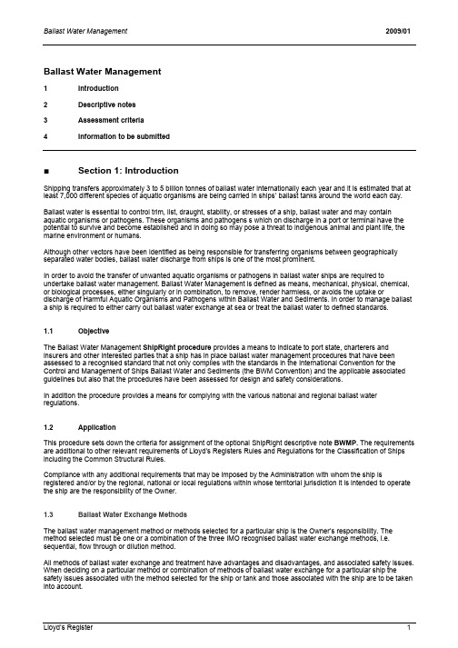
Ballast Water Management1 Introductionnotes2 Descriptivecriteria3 Assessment4 Information to be submitted■Section 1: IntroductionShipping transfers approximately 3 to 5 billion tonnes of ballast water internationally each year and it is estimated that at least 7,000 different species of aquatic organisms are being carried in ships’ ballast tanks around the world each day.Ballast water is essential to control trim, list, draught, stability, or stresses of a ship, ballast water and may contain aquatic organisms or pathogens. These organisms and pathogens s which on discharge in a port or terminal have the potential to survive and become established and in doing so may pose a threat to indigenous animal and plant life, the marine environment or humans.Although other vectors have been identified as being responsible for transferring organisms between geographically separated water bodies, ballast water discharge from ships is one of the most prominent.In order to avoid the transfer of unwanted aquatic organisms or pathogens in ballast water ships are required to undertake ballast water management. Ballast Water Management is defined as means, mechanical, physical, chemical, or biological processes, either singularly or in combination, to remove, render harmless, or avoids the uptake or discharge of Harmful Aquatic Organisms and Pathogens within Ballast Water and Sediments. In order to manage ballast a ship is required to either carry out ballast water exchange at sea or treat the ballast water to defined standards.1.1 ObjectiveThe Ballast Water Management ShipRight procedure provides a means to indicate to port state, charterers and insurers and other interested parties that a ship has in place ballast water management procedures that have been assessed to a recognised standard that not only complies with the standards in the International Convention for the Control and Management of Ships Ballast Water and Sediments (the BWM Convention) and the applicable associated guidelines but also that the procedures have been assessed for design and safety considerations.In addition the procedure provides a means for complying with the various national and regional ballast water regulations.1.2 ApplicationThis procedure sets down the criteria for assignment of the optional ShipRight descriptive note BWMP. The requirements are additional to other relevant requirements of Lloyd’s Registers Rules and Regulations for the Classification of Ships including the Common Structural Rules.Compliance with any additional requirements that may be imposed by the Administration with whom the ship is registered and/or by the regional, national or local regulations within whose territorial jurisdiction it is intended to operate the ship are the responsibility of the Owner.1.3 Ballast Water Exchange MethodsThe ballast water management method or methods selected for a particular ship is the Owner’s responsibility. The method selected must be one or a combination of the three IMO recognised ballast water exchange methods, i.e. sequential, flow through or dilution method.All methods of ballast water exchange and treatment have advantages and disadvantages, and associated safety issues. When deciding on a particular method or combination of methods of ballast water exchange for a particular ship the safety issues associated with the method selected for the ship or tank and those associated with the ship are to be taken into account.For new ships, as far as is practicable the design is to be such that ballast water exchange is facilitated and that the safety issues associated with the exchange method or methods to be use are minimised.For existing ships account is to be taken of any modifications that may be required or considered necessary in order to facilitate ballast water exchange and the safety issues associated with the exchange method or methods to be used minimised.Any installed or modifications to structural and piping arrangements may require approval for compliance with the applicable Rules and Regulations.■Section 2: Descriptive notes2.1 BWMP descriptive notesShips complying with this Procedure will be eligible to be assigned the BWMP descriptive note together with one, or a combination of the following associated supplementary characters dependant upon the method or methods of ballast water management used onboard provided that the applicable criteria in Section 3 are complied with.The eligible ballast water management methods are as follows:Sequential method (S)a process by which a ballast tank intended for the carriage of ballast water is first emptied and then refilledwith replacement ballast water to achieve at least a 95 per cent volumetric exchange.Flow-through method (F)a process by which replacement ballast water is pumped into a ballast tank intended for the carriage of ballastwater, allowing water to flow through, overflow or other arrangements.Dilution method (D)a process by which replacement ballast water is filled through the top of the ballast tank intended for thecarriage of ballast water with simultaneous discharge from the bottom at the same flow rate and maintaining a constant level in the tank throughout the ballast exchange operation.Treatment method(T)a ballast water treatment system approved in accordance with regulation D-3 of the BWM Convention. Example:ShipRight BWMP (S) indicates that the ship uses the sequential method.ShipRight BWMP (S+F) indicates that the ship uses the sequential and the flow-through methods combined. Lloyd’s Register is to be advised of any modifications to the ballast water system or the ballast water management plan that that does or may effect compliance with these procedures and that may affect the assignment of the ShipRight BWMP descriptive note.■Section 3: Acceptance criteriaRequirements3.1 GeneralIt is a prerequisite of this procedure that the ship has a Ballast Water Management Plan that has been developed in accordance with and found to comply with the requirements of regulation B-1 of the Convention and the International Maritime Organisations (IMO) - Guidelines for Ballast Water Management and Development of Ballast Water Management Plans MEPC.127 (53). In addition for ships using ballast water exchange the IMO Guidelines for Ballast Water Exchange MEPC.124(53) are to be taken into account when developing the plan.The Lloyd’s Register Model Ballast Water Management Plan can be used for the preparation of the plan. At the specific request of the Owner, or the Shipbuilder a ballast water management plan can be prepared by Lloyd’s Register.Where a new Ballast Exchange sequence is to be introduced in an existing ballast water management plan, the new sequence must be submitted to Lloyd’s Register for review and approval, as necessary.The ballast water management plan is to contain one or more ballast water exchange sequences in a format similar to the example in Appendix 1. The ballast water exchange sequences are to indicate for each sequence, at the start of the sequence, at the end of the sequence and at intermediate stages of each sequence including the worst case for each of the following:•Longitudinal strength. Checks against the assigned permissible still water bending moments and shear forces, see 3.2.•For bulk carriers, the longitudinal strength assessment for hold flooded conditions need not be carried out during the exchange sequences.•Intact stability, where required checks against the required values as indicated in the stability booklet. The effects of the combined free surface moments are to be considered, see 3.2.•Ballast inertia. For new construction, ballast inertia aspects of bulk carriers are to be considered according to the ShipRight Structural Design Assessment Procedure when applicable. For bulk carriers in service, ballast inertia aspects are to be considered using maximum lifetime accelerations and assuming a 100% filling level of theballast hold with adjacent topside and/or hopper tanks empty, as submitted in the BEP, or the acceptable sea state is to be defined.•Sloshing Where deemed necessary by Lloyd’s Register or at the owners request, sloshing aspects are to be considered according to the Rules for Ships and the ShipRight Structural Design Assessment Procedure Sloshing Loads and Scantling Assessment.•Minimum draught forward c hecks against the minimum draft forward as indicated in the ship’s plans and/or loading manual. Where not otherwise defined, this is to be taken as 0,045L or as the draught forward of anapproved condition.•Propeller immersion. Checks that at all stages of any exchange sequence the top dead centre of the propeller will remain below the still waterline.When the propeller immersion criterion can not be satisfied during an entire ballast sequence a note is to be included in the ballast water management plan in the section dealing with ‘Operational or Safety Restrictions’ as follows “the Master is advised that the propeller will not be fully immersed during some stages of ballast water exchange”. In addition in the appropriate sequence in the Ballast Exchange Sequences a similar note is also to be made against the ballast exchange sequence(s) where full propeller immersion is can not be achieved.Bridge visibility forward. Checks that bridge visibility is maintained in accordance with SOLAS V/22.It is recognised that not all ships in service comply with SOLAS 1974, Chapter V Safety of Navigation Regulation 22 Navigation bridge visibility.Where bridge visibility can not be maintained at all stages of an exchange sequence a note inserted in the ballast water management plan in section dealing with ‘Operational or Safety Restrictions’ that the Master is advised that where the bridge visibility criterion in SOLAS V/22 can not be complied with during some or all stages of the exchange sequences the Master is to take due account of the guidance given in section 5.5 to 5.8 of IMO resolution MEPC.124(53) and in addition with effect from1 January 2010 to comply the revised SOLAS V/22 as adopted by the IMO in resolutionMSC.202(81).3.2 Assessment of Longitudinal Strength, bending moments and shear forces and intact stabilityAt all times during ballast water exchange the shear forces and bending moments and intact stability criteria are to be within the limits stated in the approved loading manual and/stability booklet.It is not a condition of assignment of the BWMP notation that all ships undertaking ballast water exchange have onboard a loading instrument approved for Longitudinal Strength, bending moments and shear forces and intact stability however it is preferable.For a loading instrument to be accepted as approved it is to meet the following criteria:The ship has the class notation LI or the descriptive note LI or where the entry “Loading Instrument (C)” or “Loading Instrument” appears in the Hull Memoranda. A loading instrument approved for the calculation of Longitudinal Strength, bending moments and shear forces may also be accepted.If the ship has a stability and/or longitudinal strength calculation program or module has not been accepted or certified by Lloyd’s Register there is an option to have the stability and/or longitudinal strength calculation program or module certified in accordance with standards acceptable to Lloyd’s Register.Flow Through Method. Strength and Stability Approval is not normally required when the flow through method is the only method used. However when for example a peak or other tank that is normally partially filled is required to be pumped up for exchange purposes using the flow through method and then discharged to the normal partially filled level on completion approval of longitudinal Strength, bending moments and shear forces and intact stability maybe required.Dilution Method. Strength and Stability Approval is not normally required when the dilution method is the only method used.Flow through and Dilution Methods Combination. Strength and Stability Approval is not normally required, except where for example a peak or other tank that is normally partially filled is required to be pumped up for exchange purposes and then discharged to the normal partially filled level on completion.Sequential Method. When the sequential method is used, or is used in combination with flow through or dilution method,approval of longitudinal strength, bending moments and shear forces and intact stability for each ballast water exchange sequence will be required. Where a ship has a loading instrument approved for strength and stability Lloyd’s Register may accept the results from a loading instrument approved for longitudinal strength, bending moments and shear forces and intact stability in lieu of the above. Where the loading instrument is approved for longitudinal strength, bending moments and shear forces only, Lloyd’s Register may accept the results from a loading instrument for these aspects however approval of intact stability for each exchange sequence will be required.3.3 Assessment criteria for each methodIn addition to the general requirements in 3.1 and 3.2 the following criteria will be assessed for assignment of the relevant ShipRight descriptive note. Refer to Section 4 for details of the plans and information to be submitted.3.3.1 ShipRight BWMP (T)For the assignment of the ShipRight BWMP(T) descriptive note the criteria given in this section are to be satisfied.The installed ballast water treatment system is to be approved in accordance with the IMO Guidelines for Approval of Ballast Water Management Systems MEPC.125(53) as may be amended or;The installed ballast water treatment system is a prototype treatment system installed and under a programme approved by the Administration in accordance with regulation D- 4 of the Convention and has been or is undergoing approval inaccordance with in accordance with the IMO Guidelines for Approval and Oversight of Prototype Ballast Water Treatment Technology Programmes MEPC.140(54).3.3.2 ShipRight BWMP (F)For the assignment of the ShipRight BWMP (F) descriptive note the criteria given in this section are to be satisfied.New construction:The scantlings of the tank boundary structure are to be determined using a tank head equivalent to the full distance to the top of the tank excluding hatches, but not less than the distance to the deck at the side on which the overflow pipe is fitted.Where the overflow discharge pipe is fitted below the freeboard deck, the head is to be taken not less than the full distance to top of the discharge pipe or the distance to the ship operating draft, whichever is greater.For applicable formulations, see Pt 4, Ch 1 and Table1.9.1 of the Rules for Ships, for deep tank and watertight bulkheads in general. For double hull oil tankers, Pt 4, Ch 9, Table 9.6.1 for inner hull and longitudinal oil tight bulkheads remains applicable. For oil tankers and bulk carriers where the Common Structural Rules (CSR) are applicable CSR Oil Tankers Section 8 paragraph 2.5 or CSR Bulk Carriers Chapter 6 Sections 1 and 2 apply.Ships in service:The flow-through method is not to be utilised, unless the tank boundary structure has been confirmed as being acceptable using a tank head as defined for new construction above, and any structural modifications found necessary have been carried out. For applicable formulation, see Pt 4, Ch 1, Table 1.9.1 of the Rules for Ships for deep tank bulkheads in general. For double hull oil tankers, Pt 4, Ch 9, Table 9.6.1 for inner hull and longitudinal oil tight bulkheads remains applicable. For oil tankers and bulk carriers where the Common Structural Rules (CSR) are applicable CSR Oil Tankers Section 8 paragraph 2.5 or CSR Bulk Carriers Chapter 6 Sections 1 and 2 apply.It is not permitted to connect ballast tanks, which were not previously connected, unless the tank boundary structure is checked and found satisfactory or any necessary structural modifications are carried out.All cases:The flow-through method will only be accepted for partially filled peak tanks, provided that inadvertent exceedance of the design partial filling levels will not result in hull girder bending moments and shear forces or stability criteria exceeding the permissible values.At the specific request of the Owner, Lloyd’s Register can calculate the pressure drop of the pipework and match it to the ballast pump capacity curve.The following recommendations are to be complied with as far is reasonable and practicable:Inlet and outlet piping connections to be located as far apart as practicable, in order to improve circulation.A larger discharge pipe located in a remote position opposite from the filling pipe and a smaller discharge pipe is to be located in a position closer to the filling pipe, to improve circulation.The total sectional area of the ballast water discharge pipes is to be arranged to be not less than two times the sectional area of the filling pipe, in order to mitigate the risk of overpressure.The use of two ballast pumps simultaneously is not recommended due to the risk of overpressure, unless the system is designed for the simultaneous use of two pumps.Distribute one ballast pump to several tanks, in order to mitigate the risk of overpressure.Where overflow pipes are fitted to hatch coamings, it is recommended that they are fitted to the side coaming with a closing plate hinge arrangement and to be arranged to discharge downward.Manholes on upper deck may be used as overflow discharge, provided that a blank flange with a seat can fitted to the manhole cover arranged so that a portable overflow pipe with 90° elbow can be connected during the flow-through operation to direct the water away from the deck.Ballast water is not to be discharged from an air pipe head with float type closing appliance, unless a blank flange with a short distance piece is fitted below the air pipe head, which is to be removed during the flow-though operation.3.3.3 ShipRight BWMP (S)For the assignment of the ShipRight BWMP (S) descriptive note, the criteria given in this section are to be satisfied.The following are to be complied with:Ballast holds and large ballast tanks are to be equipped with pressure/vacuum valves or other means acceptable to Lloyd’s Register, in order to mitigate the risk of a large drop in pressure, due to the rapid change in the contents of the tank during ballast discharge by gravity. Pressure/vacuum valves valves, where fitted, are to be maintained in good working order, as a faulty pressure/vacuum valve for example by being blocked or failing to lift may result in hatch cover damage.During the intermediate stages of ballast water exchange, the machinery’s operating design characteristics (angles of inclination) are not to be exceeded.In addition the following recommendations are to be complied with as far is reasonable and practicable:If two ballast pumps are used for filling purposes the ballast water management plan is to contain a note that, when the fill level reaches 80–90 per cent, one of the pumps is to be stopped, in order to mitigate the risk of over-pressurisation.Where operational limits are specified, at least two independent pumps are to be fitted. The pumps are to be arranged such that, if one pump fails, then the stand-by pump is immediately available for operation.Sequences with partial fill level are to be avoided. Where at the end of a sequence a tank remains partially filled, conditions at ±10 per cent of the partial fill level are also to be assessed, since it is practically difficult to match the specified partial fill level whilst ship motions are experienced.Exchange sequences are to be developed such that the still water bending moments and shear forces do not exceed 85% of the permissible values, in order to account for small deviations in service.3.3.4 ShipRight BWMP (D)For the assignment of the ShipRight BWMP (D) descriptive note the criteria given in this section are to be satisfied. Where the dilution method of exchange is used adequate provisions are to be made for appropriate pumping and piping arrangements to facilitate simultaneous loading and unloading of ballast water at the same flow rate.Arrangements are to be made to continually monitoring of the ballast water level in the tanks to ensure a constant level is maintained to avoid the possibility of overfilling the tank or reducing the level in the tank.■Section 4: Information to be submitted4.1 GeneralThe following plans and information are to be submitted in all cases:(a) A copy of an approved ballast water management plan meeting the requirements in Section 3.1; or(b) a plan to be approved by Lloyd’s Register to meet the requirements of 3.1, a minimum of two copies are to besubmitted Lloyd’s Register will retain one copy of the ballast water management plan.(c) Ballast pumping and piping arrangements.(d) Air and sounding pipes arrangements.(e) Specifications and capacity curves for ballast pump and general service pump, if used for ballast transfer.(f) General arrangement and capacity plan.(g) Ballast tank and pump capacities and estimated emptying and refilling times.(h) A copy of the approval certificate for the loading instrument.(j) A copy of the ships approved loading manual.4.2 Specific requirements for the ballast water management options defined in Section 3In addition to the plans and information in 4.1:(a) For the assignment of ShipRight BWMP (T):A certificate confirming the system has been approved in accordance with in accordance with the IMO Guidelinesfor Approval of Ballast Water Management Systems MEPC.125(53) as may be amended issued by a flagadministration signatory to the Convention or by Lloyd’s Register or by a member of the International Association of Classification Societies issuing the approval certificate on behalf of a flag administration signatory to theConvention.Approved plans or diagrams of the treatment system installation, and arrangements including piping systems, connections to the ballast system, treated ballast water outlet points and sampling point(s).(b) For the assignment of ShipRight BWMP (F):For bulk carriers confirmation that that the topside and hopper tanks are or are not interconnected.(c) For the assignment of ShipRight BWMP (S):For ships in service, for the assessment of ballast inertia: approved midship section with end connection details, ballast hold volume data or curves, metacentric height, service speed and block coefficient.4.3 Optional Assessment CriteriaWhere Lloyd’s Register, at the specific request of the Owner, is to certify the stability and/or longitudinal strength calculation program or module, the information required by Lloyd’s Register’s document entitled Approval of Longitudinal Strength and Stability Calculation Programs is to be submitted.Where Lloyd’s Register, at the specific request of the Owner, is to calculate the pressure drop of the pipework and match it to the ballast pump capacity curve, the following information is to be submitted:Ballast supply piping dimensions.Overflow pipe length and size.Piping components fitted to the ballast supply line, i.e. bends, T-connections, type and number of valves.Pump capacity curve.Air vent head flow capacity curve.4.4 ModificationsPlans and particulars of proposed modifications to the ballast system or other modification to the ship which may affect the BWMP descriptive note assigned to the ship are to be submitted for approval before any work commences and the work is to be carried out in accordance with the approved plans to the Surveyor’s satisfaction.Ballast Water Management 2009/01Lloyd’s Register 10Appendix 1 Example Ballast Exchange Sequence TableAllowable limitsMin fwd draftStab’ CriteriaMax allowa ble SW BM MAX allow SW SFProp fully immers at Voyage : From: To:Expected weather:M %%MActual ValuesFo/Do/L o/Fw MtDraft Aft M Trim MDraft Fwd Stab’ CriteriaSW BM %SW SF % Prop. Immer %.InvisLe ngth MEst’ed Time Hours RemarksSequenceAP Tank No Tank No Tank No Tank No Tank No Tank No Tank No F.P.TInitial ConditionStep 1:Step 2:Step 3:Step 4:Total Time HoursBallast Water Management 2009/01Lloyd’s Register 11 The colouring of the cells where the criteria are not satisfied can enhance understandingAbbreviationsES - Empty at startFS - Full at startFL - FillingD - DischargingFE - Full at endEE - Empty at endX% - Percentage fullPercentage of tank level or symbols such as those presented below may be used asnecessary where greater detail is required , additional symbols can be defined Notes Examples Note 1: The master is advised that the propeller will not be fully immersed during this step/sequence Note 2: The master is advised that bridge visibility forward will be reduced during this step/sequence Note 3 The master is advised to verify that tanks shown as "e" or "e" are totally empty and tanks shown as "f" or "f" are totally full, at the start and end of the step/sequence Note 4: Where two ballast pumps are used for filling purposes, when the full level reaches 80% - 90%, then one of the pumps is Note 5: The indicative times for ballast exchange by flow-through method of …tanks(s) id…are provided separately For conservative reasons, where at the end of a step / sequence a tank remains partially filled, additional conditions at ± 10 % of the partial fill level are also be assessed, since it is practically difficult to match the specified partial fill level whilst ship motions are experienced Aim to develop sequences where the still water bending moments and shear forces do not exceed 85% of the permissible values, in order to account for small deviations in service, so that the master and the appointed ballast water。

The choice you make should meanpeace of mind tomorrowIf you find the information in this document useful, you can download the complete guide at:/pureballast/knowledge/When selecting a major onboard system, the choice of supplier can be just as important as the choice of system itself. This is especially true in an application like ballast water treatment, where there are not only new technologies, but also a wide range of new suppliers to the marine industry. Considering that a ballast water treatment system should last the vessel’s lifetime, there is no advantage in taking risks.Recent clarification from the U.S. Coast Guard (USCG) puts this in the spotlight. In a blog post dated 22 September 2017, the USCG explains what happens if the manufacturer of a ballast water treatment system goes out of business. Simply put, the system cannot be operated, maintained or repaired with parts thatare not included in its type approval. So if no company purchases the technology and updates the type approval certificate within five years, the type approval will expire and no new parts will become available to keep existing systems in compliance.In light of this, it becomes important to consider not only the capabilities of the ballast water treatment system, but also the capabilities and track record of its supplier. Global presence, marine history and repeat business are all worth evaluating as indicators of future reliability.This document can be useful in such an evaluation. The text is an excerpt from “Making sense of ballast watermanagement”, a comprehensive guide to regulations and compliance alternatives. Chapter 5 and Appendix H, which are presented here in their entirety, offer concise background and a checklist for supplier discussions.Supplier selection guide As discussed throughout this book, there are numerous factors to consider when evaluating potential equipment suppliers for a ballast water treatment system. These factors relate not only to the operational strengths and limitations of the systems themselves, but also to the suppliers’ own capabilities.Asking the right questionsThe following is a summary of the most important questions to ask when considering a potential supplier in ballast water treatment. The questions highlight critical differences that will impact upfront system and installation costs, but more importantly the long-term costs over the system’s lifetime.A checklist for use in supplier discussions can be found in Appendix H.1. Can the supplier ensure performance in widely diverse operating conditions?The supplier should provide a fully compliant ballast water treatment system without limiting the vessel’s operations. The system should have both IMO and USCG type approval and offer a full range of options to avoid restricting the place or manner in which the vessel does business. It is important to make sure the system is capable of performing in fresh, brackish and marine water, as well as in all water temperatures. In the case of a UV treatment system, it should also perform in conditions where UV transmittance is low. 2. Has an authorized third party conducted type approval tests of the supplier’s equipment?Type approval testing by an authorized third party is important to secure transparency, validity and ultimate-ly system compliance. Third-party testing bodies can ensure a controlled testing environment and realistic test conditions, which will prevent system deficiencies from being overlooked. Much is known today about the control mechanisms needed to ensure compliance – serious suppliers seek third-party transparency and perform their tests with water that contains naturally occurring organisms to ensure compliance in all possible conditions.3. Does the supplier have a long track recordof working in the marine industry?Selecting a true marine supplier with extensive industry experience helps guarantee that a system has been designed with an understanding of the specific demands facing different types of vessels operating in a range of water conditions. For example, many UV treatment systems actually have their roots in drinking water treatment. Because they are adaptations of land-based technologies for water purification, they are less suited to common marine circumstances such as low UV transmittance. Choosing a system specificallydeveloped for marine use avoids these problems.4. Is the supplier’s system easy to installand operate?If the supplier has considered simplicity of installation, the system should offer a small footprint and flexibility of placement ‒ which are particularly important for retrofits. A system that incorporates major components into the ballast water piping and requires no additional tanks or ventilation systems will generally be easier to install. Operation should be fully automatic with an intuitive control system interface, and there should be never be a need for manual intervention from the crew.5. Has the supplier received repeat ordersfrom customers?Nothing says more about a ballast water treatment system or its supplier than the trust placed in them by customers. An extensive reference list is valuable, but the most important references are those where the same customer has purchased a system multiple times. The decision to purchase again, based on successful operation at sea, is the best seal of approval available.6. Has the supplier successfully installed a large number of ballast water treatment systems?The supplier’s reference list should be examined critically for the number of systems installed and still in operation aboard both newbuilds and existing vessels. Retrofit projects in particular demand considerable coordination of numerous partners. The more exten-sive the supplier’s experience in this area, the more likely the supplier’s ability to facilitate a smooth installation, which is important for ensuring the proper performance of the system in the long term.7. Does the supplier have a track recordof meeting delivery times?A spotless delivery track record is vital. If a supplier is unable to get equipment to the shipyard during the scheduled time slot, there can be a great deal of additional expense as well as lost income opportuni-ties. This has become a critical issue with the entry of the BWM Convention into force, as the increased number of vessels installing treatment systems impacts the availability of equipment and shipyard slots.8. Can the supplier minimize time out of service for installation and commissioning?While the installation of a ballast water treatment system is a major undertaking, the supplier should be able to minimize the time during which the vessel is out of service. With smart supply solutions and good planning, it should be possible to limit downtime at a capable shipyard to two weeks. Some suppliers may also have the capability to perform much of the installation while sailing, without interrupting the vessel’s normal course of operation.9. Does the supplier have global support capabilities?The ballast water treatment system is a solution that will be with the vessel for many years. This makes it important to choose a stable supplier with a strong global network, who can provide parts and long-term support wherever the vessel sails. In the unlikely event of a system failure, it is important to have 24/7 access to the supplier’s services, no matter where the vessel is.10. Does the supplier have an extensiveand flexible service offering?A ballast water treatment system is a major investment that requires expert maintenance to secure lasting, compliant performance. Periodic inspection and service from the original supplier can safeguard that investment by verifying full system functionality according to the system’s type approval. A tailor-made performance agreement with the supplier is a flexible solution that offers the ideal service for the vessel’s specific needs at a fixed, budgeted cost.Appendix H: Ballast water treatment system supplier checklistThe following checklist can be used when evaluating suppliers according to the key factors presented in this book. Rate each supplier on a scale from 1 to 5,where 5 indicates the strongest performance inrelation to the question. The higher the overall marks, the stronger the supplier.。
MADE INUSAYour knowledgeable and trusted partner for the best in water management solutionsCommercial StormwaterCommercial Product SolutionsPermeable Grass Pavers Permeable Gravel Pavers Trench & Channel Drains Underdrain & French Drain Sports DrainStormChambersSince 1972, NDS has been producing plastic drainage and landscape products.From the beginning, our commitment to leading the industry has been unwavering, leading to remarkable innovations and state-of-the-art products that fit every environment, every schedule, every need.1970's1980's1990's2000's2010>PRESENTIntroduced the first plastic catch basin · Plastic grates · Channel drains Expanded drainageproduct offeringalong with nationalsales & distribution· New basin grates· Additionalchannel drainsFocused ongrowth including:· 18” & 24” Basins· Pro Channel· Metal gratesInvested in newproduct innovations:· Dura Slope™Pre-slopedTrench Drain· PermeablePaver SystemsExpanded productlines & partnerships:· FILCOTENFiber-reinforcedTrench Drains· Dura Flo™ HD· Control Zone Kits· StormChambers™Stormwater Solutions for a Variety of ApplicationsNDS provides a diverse range of stormwater management solutions to capture, convey and retain stormwater. Commercial SpacesScalable and flexible solutions for office buildings,banks, hotels, grocery stores and more.· Stormwater detention and infiltration· Reinforced turf and gravel with delineators· Biofiltration and bioretention· Parking and service area runoffParks and Recreation AreasScalable and aesthetic solutions to help you safelymaintain golf courses, sports fields, patio and pool decksand other outdoor recreational environments.· Mitigate stormwater runoff· Eliminate standing water· Reinforced turf and gravel delineatorsGovernment and Public SpacesSolutions to maintain safety and regulatory compliancein numerous public and government applications suchas schools, government buildings and parks· Parking and service areas· Biofiltration and bioretention· Large roof and courtyard runoffRoad and HighwayLoad-rated DOT-compliant stormwater managementsolutions that can withstand the weight of heavy machinery,enabling you to protect roadways and pedestrian areas fromunsafe standing water and excess runoff.· Bioswale· Roadway runoff· Emergency access· Streets and sidewalksSample ProjectsEZ RollGrass Fire LaneFILCOTENIndustrial (B.G.&E. MD)FILCOTENRoadway (US Gov. in VA)FILCOTENCommercial Courtyard Dura Slope Track StormChamber DetentionDura Slope IndustrialEZ RollGrass ShoulderEZ Roll GrassFire Lane (LG Corporation in NJ)FILCOTENDrainage (Public Road in NJ)FILCOTEN Train Station Dura Slope Pool (Marriott in CA)FILCOTEN Parking Garage EZ Roll GravelParking (Frontier Town/OGS NY)EZ RollGravel AccessCatch Basins & Grates1Faster install, snaps together 2High efficiency with 25% less labor 3No breakage with HDPE 4Higher capacity5Light weight, easy to carry6No cutting plywood, comes with dummy 7Flex couplings give smooth radius “D” areas 8Simple to cut with wood saw 9Freight is included 10Made in USAEZ-Track ™Sports Drain SystemDesigned specifically for draining 400-meter running tracks, Dura Slope ™ Radius Couplings allow 3° of deflection between trench drain sections, making an adjustable radius easily achievable for standard tracks and other curving applications.3°3°Patent PendingFlexible Radius CouplingRadius Couplings80-120 FT RadiusNo polymers (Green Technology)No releasing agents used in de-molding DIN load rated A to F, 134,000 lbs.Catch BasinSlottedGalvanized Steel PerforatedGalvanized Steel MeshGalvanized Steel Slot Top Galvanized or Stainless SteelFILCOTEN Grate Materials & StylesHeavy-Duty Solutions for Every ApplicationWe can help size your drain and provide a layout.Tell us your application; Load capacity; invert height; required flow... Contact us for assistance: 800-726-1994|*********************Made to OrderAdditional Styles and finishes available upon request.!Slotted Ductile Iron Longitudinal Bar Ductile Iron Honeycomb Plastic KiaroVia VilleInlet Start Chamber Inlet Pipe Opening SedimenTrapNDS ® StormChamber ® Plan View(Configuration Example)NDS ® StormChamber ® Elevated ViewStructural ComponentsMeets H-20 Standards· Up to 16’ cover when deep installs are required for the 34” and up to 12’ for the 44”· The 18" can handle a maximum of 16' of cover, but is better suited for shallow installation needs · Withstands the most extreme environments· Material bends instead of breaks giving it a brittleness temperature of -107°F vs. industry average of -2°F · 100 year life expectancy, longest on the marketStackAllows for deeper installation and a smaller footprint· 34” Chambers: Capable of 3-layer stacking· 44” Chambers: Contact NDS DesignWorx for any projects that may need stacking · We offer expert site-specific design guidance based on 20 yearsof successful completion of projectsGravel-Free French Drain• All-in-one system with up to 50% labor savings • 30% better flow than gravel French drains • More accessible than stone and pipe • Suitable for a wide range of soil types • Crush resistant with proper installation • Built to last with a 100-year product lifespan • Compliant with applicable drainage codes and standards • ICC approvedEZ-FlowEngineered French Drain SolutionLight WeightLandscape DrainsBehind Wall or FoundationEZflow is an engineered French drain system incorporating a polystyrene aggregate that provides enhanced performance, strength, filtration and longevity. EZflow is faster and easier to install than gravel and pipe, saving time and money on your project.Performance InnovationEngineered flow channels increase void space, creating improved water flow and greater storage.Lightweight expanded polystyrene aggregate offers structural integrity and resists compaction.30-Sieve Geotextile Mesh Geosynthetic AggregateASTM F405 Rated Corrugated Pipe33 41 43 Synthetic-Media French Drains10' EZ-1501F6" Corrugated Pipe 6C07 6" Internal CouplingEZ-1501F10' Storage Volume = 45.8 Gallons (6,1225 CU. FT.) Per Section, Flow Rate = 345.0 GPM (1% Slope)Storage Volume = 45.8 Gallons (6,1225 CU. FT.) Per Section, Flow Rate = 345.0 GPM (1% Slope)Tongue & Groove clips reduce installation timeEZ Roll ™ Gravel Paver Rolls53,683 psf.Available in:3.87 ft. x 149 ft. rolls – 577 sq. feet total Black GP4X150GrayGP4X150G TanGP4X150TBrick Red GP4X150REZ Marker™ Parking Delineators300 PSI class “C” compressive strengthAvailable in:2.7" hexagonal shape0.40" profile above paver grade• Molded polypropylene, impact copolymer • Easy clip-in installation• Self-cleaning: Raised dome design prevents debris from stickingEZ Roll ™ Grass Paver Rolls53,683 psf.Available in:3.96 ft. x 24 ft. rolls – 97 sq. feet total 3.96 ft. x 152 ft. rolls – 601.6 sq. feet total• Cells filled with wet soil have a compressive strength of 400,000 psf• Product ships in large rolls f or easy rollout • Easy to connect locking tabs on sides and endsEasy to installpre-assembled rollsEasy to installpre-assembled rollsCan only be used with NDS EZ Roll ™ pavers• Cells filled with 3/8" Gravel have a compressive strength of 500,000 psf• Product ships in large rolls f or easy rollout • Easy to connect locking tabs on sides and endsto ensure longevity. Barrier Panels have 1/2" raised vertical ribs running38"24"18"12"With NDS DesignWorx ™We Can Draft Your Plan.NDS civil engineers and expert technicians are ready to partner with you to make your project successful. Our team will work with you to assess the feasibility of incorporating NDS products to align with best stormwater practices and save costs.We will evaluate your plans & help in preparation of submittal drawings, including:Just Upload CAD or PDF Thru Website:/submityourdesignFind Us on CAD Details:!List of all materialsIdentify all partsDirection of flow detail Installation detailsYour company ontitle blockDesignWorx®DesignWorx®Left to Right:Capacity Charts Lab TestingWritten CSI DIV Specifications Installation Details PDF/DWGSearch for specifications, technical documents and construction details.VisitA Powerful Tool to Find What You Need FastComprehensive ContentVideo LibraryProduct LiteratureMobile AppLeft to Right:Installation ManualsProduct Brochures Case StudiesGet NDS on the Go!Download our Mobile App to access our productcatalog, online calculators and planning tools.Search for NDS DrainageInstallation VideosTools & CalculatorsVideos Tools/Calculators DownloadsCaseStudiesDesignWorxRequesta QuotePersonal Support – OnsiteLunch and LearnNDS can provide a 1-hour seminar, during lunch, at your offices. Content covered is relevant to todays stormwater LID challenges for; engineers, landscape architects, surveyors, estimators or contractors. In addition to lunch, we can provide certificate of attendance for 1 educational credit hour. Topics covered include solutions ranging from permeable grass and gravel paving systems to area drain/trench drain/drain slots.Jobsite VisitsWe have feet on the street and can provide on-site installation training, technical support and problem solving. Our goal is tofacilitate the best possible project outcome for your client.。
船舶压载水管理计划BALLAST WATER MANAGEMENTPLANWESTLION SHIP MANAGEMENT CO., LTD.目录Contents章节标题页码Chapter Title Page 1.介绍 2Introduction2.船舶资料 4Ship’s particular3. 负责人员及职责 5Responsible officer any their duties4.培训和教育 6Training and education5.压载水管理的手段8Ballast water management measures6 安全措施13Safety Precautions7 更换压载水程序19Procedure For Ballast Water Exchange8 记录和报告程序20Recording and Reporting Procedures9 附录23APPENDIXES压载水管理计划BALLAST WATER MANAGEMENT PLAN1.介绍与目的Introduction and object1.1数个国家的研究显示在船上压载水和淤泥中的多种细菌、植物和动物,虽经过数个月的海上旅程,仍能存活。
随后在各港口国水域排放压载水或淤泥,将产生对当地的人类,动植物生态,及海洋环境构成威胁的有害水生有机体和病原体。
虽然其他媒介已被确定引起有机体在分隔水体之间的传播,但船舶排出的压载水却被列于最显著的媒介之中。
Studies carried out in several countries have shown that many species of bacteria, Plants, and animals can survive in a viable from in the ballast water and sediment carried out in ships, even after journeys of several months’ during. Subsequent discharge of ballast water or sediment into the water of port States may result in the establishment of harmful aquatic organisms and pathogens which may pose threats to indigenous human, animals and plant life, and the marine environment. Although other media have been identified as being responsible for transferring organisms between geographically separated water bodies, ballast water discharge from ship appears to have been among the most prominent.1.2为了减少船舶压载水在各海区之间传播对当地海洋中的动植物及海洋环境有危害的海生物的可能性,并符合国际海事组织《为减少有害水生物和病原体传播的对船舶压载水控制和管理的指南》(RESOLUTION A。
Ballast water managementOn 8 September 2017, the International Convention for the Control and Management of Ships’ Ballast Water and Sediments (the Convention) will enter into force internationally.From this date, all vessels are required to manage their ballast water and sediments in accordance with the Convention and Biosecurity Act 2015.The Australian Ballast Water Management Requirements Version 7, available from.au/ballast, explain how vessel operators should manage ballast water while in Australia, in compliance with the Biosecurity Act 2015.New requirementsManagement plans and certificationFrom 8 September 2017, all internationally operating vessels entering Australia will require an: • approved Ballast Water Management Plan• International Ballast Water Management Certificate.These documents must be in the form prescribed by the Convention.Case by case exemptions from the requirement to obtain certification, or meet the D-2 discharge standard apply in some circumstances. See .au/ballast for more information. Management of Australian-sourced ballast waterApproved methods of ballast water managementFrom 8 September 2017, Australian-sourced ballast water must be managed by an approved method prior to discharge in a subsequent Australian port. Approved methods include:• ballast water exchange• use of an International Maritime Organization type approved ballast water treatment system • discharge to a ballast water reception facility• on-board conversion of sea water to potable water for use as ballast• retention (sometime known as tank-to-tank transfers).Exceptions to ballast water managementVessels do not need to use an approved method of ballast water management if all ballast water in a tank is:• taken up on high seas• taken up and discharged in the same place (within port limits)• taken up and discharged within a declared same risk areaDepartment of Agriculture and Water Resources Ballast water management for international vessels• covered by a low risk exemption (this applies to international vessels managingAustralian-sourced ballast water between specific ports where ballast transfer is determined to below risk).Vessel operators can apply for low risk exemptions using the Australian Sourced Ballast Application, orby updating their existing ballast water report, in the Maritime Arrival Reporting System (MARS).Register your vessel, and learn more about MARS from August 2017 at.au/biosecurity/avm/vessel/marsBallast water reportingThere is no change to the way an international vessel provides a pre-arrival report on their ballast water(through the ballast water report application in MARS).Ballast water reports should:• be submitted no later than 12 hours before a vessel intends to discharge ballast water• contain a forward itinerary of subsequent Australian ports where known.Where the vessel continues their voyage to a subsequent port within Australia, the vessel’s operator mayreport any Australian-sourced ballast water operations through the ballast water report in MARS.Ballast water exchangeVessel masters who cannot comply with the following requirements should phone the Maritime NationalCoordination Centre on 1300 004 605 for advice. Failure to do so before discharging ballast water mayresult in civil penalties for the operator of the vessel.Where to exchange international waterVessels carrying internationally sourced ballast water must conduct ballast water exchanges as faras possible from the nearest land, which is:• at least 12 nautical miles from the nearest land, and in water greater than 50 metres deep• where possible, more than 200 nautical miles from the nearest land and in water greater than200 metres deep.Where to exchange Australian-sourced ballast waterVessels carrying Australian-sourced ballast water must conduct ballast water exchanges:• at least 12 nautical miles from the nearest land, and in water greater than 50 metres deep.Ballast water must not be discharged or exchanged in:• Ningaloo Marine Reserve, Western Australia• Great Barrier Reef Marine Park, QueenslandPlease see the Australian Ballast Water Management Requirements Version 7(.au/ballast) for exchange requirements when operating between ports in the GreatBarrier Reef Marine Park area.Ensuring complianceBiosecurity officers will conduct inspections to ensure compliance with Australian domestic ballastwater regulations.。
MANAGEMENT PLAN1. The purpose of this Plan is to meet the requirements for the “Control and management ofship’s ballast water and sediments”. It provides standard operational guidance for the planning and management of ships’ ballast water and sediments and describes safe procedures to be followed.2. This Plan is written in accordance with the requirements of Regulation B-1 of the“International Convention for the Control and Management of Ships’ Ballast Water and Sediments, 2004” (the Convention) and the associated “Guidelines for Ballast Water Management and the Development of Ballast Water Management Plans” – IMO Resolution MEPC 127(53).3. Once approved by the Administration, no alteration or revision shall be made to the maincontents up to Section 13 without the prior approval of the Administration.4. This Plan may be inspected on request by an authorized authority.Issue: 01 June 06MANAGEMENT PLANFor Compliance with Regulation B-1 of the international Convention for the Control and Management of Ships’ Ballast Water and Sediments 2004 and the IMO ‘Guidelines for Ballast Water Management and Development of Ballast Water Management Plans’ Resolution MEPC 127 (53).SHIP NAME:IMO No.M.V.IMO Number:BALLAST WATER MANAGEMENT PLAN1. The purpose of this Plan is to meet the requirements for the “Control and management ofship’s ballast water and sediments”. It provides standard operational guidance for the planning and management of ships’ ballast water and sediments and describes safe procedures to be followed.2. This Plan is written in accordance with the requirements of Regulation B-1 of the“International Convention for the Control and Management of Ships’ Ballast Water and Sediments, 2004” (the Convention) and the associated “Guidelines for Ballast Water Management and the Development of Ballast Water Management Plans” – IMO Resolution MEPC 127(53).3. Once approved by the Administration, no alteration or revision shall be made to the maincontents upto Section 13 without the prior approval of the Administration.4. This Plan may be inspected on request by an authorized authority.Exceptions•This plan would not apply to the discharge of ballast water and sediments if the Master reasonably decides that compliance with these procedures and IMO Guidelines would threaten the safety or stability of the ship, its crew, or its passengers because of adverse weather, ship design or stress, equipment failure, or any other extraordinary condition.The Master shall record such events in the Ballast Water Record book.•The requirements of regulation B-3 (Ballast Water Management for Ships) or any measures adopted by a Party pursuant to Article 2.3 and Section C of the Convention, shall not apply to:1. the uptake or discharge of Ballast Water and Sediments necessary for the purpose ofensuring the safety of a ship in emergency situations or saving life at sea; or2. the accidental discharge or ingress of Ballast Water and Sediments resulting fromdamage to a ship or its equipment:.1 provided that all reasonable precautions have been taken before and after the occurrence of the damage or discovery of the damage or discharge for the purpose of preventing or minimizing the discharge; and.2 unless the owner, Company or officer in charge willfully or recklessly caused damage; or3. the uptake and discharge of Ballast Water and Sediments when being used for thepurpose of avoiding or minimizing pollution incidents from the ship; or4. the uptake and subsequent discharge on the high seas of the same Ballast Waterand Sediments; or5. the discharge of Ballast Water and Sediments from a ship at the same location wherethe whole of that Ballast Water and those Sediments originated and provided that no mixing with unmanaged Ballast Water and Sediments from other areas has occurred.If mixing has occurred, the Ballast Water taken from other areas is subject to Ballast Water Management in accordance with this plan.Ballast Water Management PlanParticulars Ship’sShip’s ParticularsShip’s nameShip typeFlag Port of registryGross tonnageIMO NumberLength (BP)Beam International call signMinimum Draft forward (loading manual)Deepest Ballast Drafts (normal weather)Ballast hold(s) for heavy weatherDeepest Ballast Drafts (heavy weather)Total water ballast capacityBrief Description of the Ballast WaterManagement method used on the shipAppointed ballast water management officerAdditional ballast water management officerRevision Record for Ballast Water Management PlanRev. No Date Section Page Remarks ApprovedBallast Water Management PlanDate/Rev 01.07.08 / 09Amendment HistoryPage 1 of 2Revisions or additions will be issued to update this plan as and when necessary. However the non mandatory information in Section 14 and 15 will be altered or revised by the Company. The copyholders in office and Master on board vessel are responsible for updating this plan with the latest revisions issued.Deleted InsertedRevision NumberSection Nr. Date Section Nr. DateBrief description of changes01 101.06.06 101.10.06 1.1 Exemptions -added 01 3 01.06.06 3 01.10.06 Overflow & Filling line Dataand Time required for Flow-through Method added01 13 01.06.06 13 01.10.06Training Record SheetAdded01 15 01.06.06 15 01.10.06 National Requirementsrevised and Appendices re-issued02 15-Appendix 14 & 14B 01.10.06 15-Appendix14 & 14B 01.09.07BW Programs on the West Coast of North America revised; National Requirement –USA-Washington State revised03 15-Appendix Section 2 01.10.06 15-Appendix Section 2 01.10.07National Requirement –Australia - Guide to AQIS forms for vessel clearance revisedQPAR (Pratique) formrevisedAustralian Ballast Water Management Requirement version 3, 01 June 07 added04 7 01.06.06 7 01.11.07Procedures for Safe TankEntry added04 12-Ballast Water Sediment Handling Log - 12 –Ballast Water Sediment Handling Log01.11.07Ballast Water SedimentHandling Log revised 05 12-Ballast Water Reporting Form - 12-Ballast Water Reporting Form 01.12.07 Ballast Water Reporting Form- Salinity of BW noted. Annotated Sample Form added.06 15-Appendix 14B 01.09.07 15-Appendix14B01.02.08 National Requirement –USA-Washington Staterevised-Oregon State added 06 15 01.10.06 15 01.02.08 Oregon State added in theAppdx List of Countries withNational Requirements 07 7 01.11.07 7 & Appendix 7 01.03.08Heavy Ballast Operation(Ballasting Cargo Hold) RiskAssessment added toSection 7 & Appendix 7 08 2 01.06.06 2 01.05.08 Pumping Diagram in engineRoom and ManholeArrangement Plan added 08 3 01.10.06 3 01.05.08 3.4.2 Notes for FlowThrough method of BWexchange revisedBallast Water Management PlanDate/Rev 01.07.08 / 09Amendment HistoryPage 2 of 2Deleted InsertedRevision NumberSection Nr. Date Section Nr. DateBrief description of changes08 4 01.06.06 4 01.05.08 Ballast Water SamplingPoints and SedimentCollection revised08 6 01.06.06 6 01.05.086.2.2 Flow Through Methodrevised08 9 01.06.06 9 01.05.08Sediment Control andRemoval Methods added 09 501.06.06 501.07.08 5.1.1 & 5.1.2 Sequential &Flow Through Methodrevised09 8 01.06.06 801.07.088.1 Procedures for BW exchange revised; 8.4Bridge Visibility Forward revised09 9 01.05.08 901.07.08Sediment Management andDisposal revised09 15-Appdx 2 15-Appdx 2Australian Ballast Water Management Requirementsupdated to version 4 - Mar 08.Reviewed and Approved byDesignated Person AshoreManual updated with latest revisionsCopy Holder’s SignatureRECORD OF CIRCULATIONThis document to be circulated to ships staff that will be responsible for Ballast Water Management. After reading the Ballast Water Management Plan, it is to be signed and returned to the Ballast Water Management Officer.Name Rank Date Joined Signature and datePage 1 of 1 ContentsShip’s Particulars1Purpose1.1Exemptions2Plans/Drawings Of The Ballast System3Description Of The Ballast System3.1Tank arrangement, and tank capacities :3.2Capacities Of Each Pump Available for Ballasting / Deballasting operation3.3Sample Ballast Arrangements3.4Overflow and Filling line data (for flow through and dilution method)3.4.1Overflow & Filling Line Data3.4.2Time Required for Flow-through Method3.5Ballast arrangements for Light Ballast and Heavy Ballast conditions4Ballast Water Sampling Points4.1Ballast Water Sample And Sediment Collection5Operation Of The Ballast Water Management System5.1Ballast Water Exchange5.1.1 Sequential Method5.1.2 Flow through Method5.1.3 Dilution Method5.2Treatment Systems5.3Precautionary Practices For Loading Ballast5.3.1Non-Release Or Minimal Release Of Ballast Water5.3.2Discharge To Reception Facilities6Safety Procedures For The Ship And The Crew6.1Exchange at Sea6.2Safety Considerations6.2.1Sequential Method6.2.2Flow through Method6.2.3Dilution Method6.3Conditions Under Which Ballast Water Exchange At Sea Should NOT Be Undertaken6.3.1Informing the Company6.4Precautionary Advice to Masters When Undertaking Ballast Water Exchange Operations 7Operational Or Safety Restrictions7.1Procedures for Safe Tank Entry7.2Heavy Ballast Operation (Ballasting Cargo Hold) Risk Assessment8Ballast Water Management Methods Used On Board8.1Procedures For Ballast Water Exchange8.2Ballast Inertia8.3Sloshing8.4Bridge Visibility Forward9Sediment Management And Disposal10Methods Of Communication For Discharge Of Ballast In Waters10.1Action to be taken by the vessel where coastal state has specific procedures fordischarge of ballast water:10.2Actions to be taken by the vessel where the coastal state has no specific requirements 11Duties Of The Ballast Water Management Officer12 Recording Requirements13Crew Training And Familiarisation13.1Training Record for Ballast Water Management Manual14Reference Documents15Port State (National) RequirementsSection 1Page 1 of 1 Purpose1 PurposeBallast water is essential to control trim, list, draught, stability, or stresses of the ship.However, ballast water may contain aquatic organisms or pathogens which, if introduced into the sea including estuaries, or into fresh water courses, may create hazards to the environment, human health, property or resources, impair biological diversity or interfere with other legitimate uses of such areas.The selected methods of ballast water management take into account the need to ensure that Ballast Water Management practices used to comply with this Convention do not cause greater harm than they prevent to the environment, human health, property or resources of any States and the safety of the ship.It is estimated that at least 7,000 different species are being carried in ships’ ballast tanks around the world. Studies carried out in several countries indicated that many species of bacteria, plants, and animals can survive in a viable form in the ballast water and sediment carried in ships, even after journeys of several months duration.Subsequent discharge of ballast water or sediment into the waters of port States may result in the establishment of harmful aquatic organisms and pathogens which may pose threats to indigenous human, animal and plant life, and the marine environment. When all factors are favourable, an introduced species by survive to establish a reproductive population in the host environment, it may even become invasive, out-competing native species and multiplying into pest proportions.Although other media have been identified as being responsible for transferring organisms between geographically separated water bodies, ballast water discharge from ships appears to have been among the most prominent. As a result IMO has developed guidelines for the development and implementation of a Ballast Water Management on board ships aiming to assist Governments, appropriate authorities, ships masters, operators, owners and port authorities, as well as other interested parties, in preventing, minimising and ultimately eliminating the risk of introducing harmful aquatic organisms and pathogens from ships’ ballast water and associated sediments while protecting ships’ safety.Good record keeping is critical to the success of a sound ballast water management program.The appointed ballast water management officer is responsible for ensuring the maintenance of appropriate records and that ballast water management and/or treatment procedures are followed and recorded.The function of the Ballast Water Management Plan is to assist in complying with IMO guidelines and quarantine measures intended to minimise the risk of transplanting harmful aquatic organisms and pathogens from ships’ ballast water and associated sediments, while maintaining ship safety.As part of this function the plan provides information to port state control and other authorised officers about a ship’s ballast handling system, sampling points and ballast water management system.The plan should not be used or regarded as a guide to ballasting.1.1 ExemptionsNo exemption certificates that may be granted under regulation A-4 of the Convention is applied to this ship.Any future exemptions should also be recorded in the Ballast Water Record Book.Ballast Water Management Plan Date/Rev 01.05.08 / 01Section 2Plans/Drawings of the Ballast System Page 1 of 12 Plans/Drawings Of The Ballast SystemFollowing plans can be referenced inBallast tank arrangement and Ballast capacity plan Approved Trim and Stability booklet orLoading Manual.A ballast water piping and pumping arrangement,including air pipes and sounding arrangementsGeneral Arrangement Plan Ballast water pump capacities Pumping PlanA plan and profile of the ship, or a schematicdrawing of the ballast arrangementGeneral Arrangement PlanList and/or diagrams indicating the location of sampling and access points in pipelines and ballast water tanks. Pumping PlanPumping diagram in Engine Room Manhole Arrangement Plan• Tank apacity(m ) ps Available 3Description Of The Ballast System3.1Tank arrangement, and tank capacities: • 100% C 3• Pum • Forepeak • • • 1 DB P&S • • • • • • • • • • • •• • • 1 TST P&S • • • • • • • • • • • •• •• After Peak••Ballast Holds 00% Capacity (m 3) Pumps Available 1mp (1• Rated Ca 3.2Capacities Of Each Pump Available for Ballasting / Deballasting operation • Pu each) pacity• Main Ballast• M 3/Hr •Pump • Mtrhead • Bilge &• M 3/Hr• 5 tr head Ballast Pump 25/6• M •Fire & GS • M 3/Hr• 25/6Pump5• Mtrhead3.3 ship’s approved Trim and Stability Booklet.3.4 a g li r gh n m Refer to Pumping Plan for the nominal diameter of t w (a fillin 3.4.1 Overflow in Sample Ballast ArrangementsRefer to Ballast conditions given in the Overflow nd Fillin ne data (fo flow throu and dilutio ethod)he overflo ir vents) and g lines.& Filling L e DataTANK No. per tank (Air vent or overflow line per tank)Overflow Line nominal diameter (mm) Overflow Line total cross section area(mm ) Filling line nominal diameter (mm)Filling Line total cross section area(mm )overflow I Filling Line total cross section areaofoverflow22Ratio orFPT1DB P&S2DB P&S3DB P&S4DB P&S5DB P&S1 TST P&S2 TST P&S3 TST P&S4TST P&S5 TST P&S3.Time Required for Flow hrough Method4.2 -tBallast T PumpTime for 3 Exchangeank Capacity FPTNo,1WBT(P)(S)No,2WBT(P)(S)No,3WBT(P)(S)No,4WBT(P)(S)No,5WBT(P)(S)No,1TST (p)(S)No,2TST (P)(S)No,3TST (p)(S)No,4TST (P)(S)No,5TST (p)(S)Notes for Flow Through method of BW exchange:• Only one pump should be used for ballasting / de-ballasting a single ballast tank, as faras possible. • Time for BW exchange in above table has been calculated using maximum rate for onepump. • Ratio of Overflow / Filling Line Total Cross Section Area should be more than 2.0, whenFlow Through method is used. Therefore, manhole cover of tanks should be opened to keep the ratio more than 2.0. •Safety measures (eg: notice, grill cover, safety hoops or restricting access to the area on deck) should be taken to avoid crew slipping and falling in the tank when man hole covers are opened.• As it is not practical to keep manhole covers of Fore Peak Tank, Double Bottom Tanks,.5 Ballast arrangements for Light Ballast and Heavy Ballast conditions Refer to Pumping Plan and Trim and Stability booklet.After Peak tanks, located in fore castle, cargo holds, steering gear, Sequential method is preferred for BW exchange in these tanks.3Ballast Water Sampling Points Page 1 of 14 Ballast Water Sampling PointsBallast water samples may be drawn through:•Ballast tank sounding pipes (identified in the pumping plan)•Drain cock on ballast pumpsSediment samples of ballast tanks may be taken through:•Manholes (identified in the manhole arrangement plan)4.1 Ballast Water Sample And Sediment CollectionSediments of ballast tanks may be taken from the tanks after observing enclosed space entry procedures.Compliance monitoring may be undertaken by authorized officers (e.g. Port State Control), by taking and analyzing ballast water and sediment samples from ships.There is unlikely to be any need for crewmembers to take samples except at the express request, and under the supervision, of an authorized officer.Authorized officers must be advised of all safety procedures to be observed when entering enclosed spaces.Where ballast water or sediment sampling for compliance or effectiveness monitoring is being undertaken, the time required to analyze the samples shall not be used as a basis for unduly delaying the operation movement or departure of the ship.When sampling for research or compliance monitoring, authorized officers (e.g. Port State Control) should give as much notice to the Master as possible that sampling will occur, to assist the Master in planning staffing and operational resources to assist.The Master has a general obligation to provide reasonable assistance for the above monitoring and information pertaining to ballast arrangements and sampling points.Port State Authorities should indicate to the master or responsible officer the purpose for which the sample is taken (i.e. monitoring, research or enforcement).Port State Authorities may sample or require samples to analyze ballast water and sediment, before permitting a ship to discharge its ballast water.Operation of Ballast Water Management System Page 1 of 35 Operation Of The Ballast Water Management SystemThe necessity of pre-planning is to ensure that all safety considerations as addressed in Sections 6 and 7 are in compliance with ballast exchange, ballast water treatment or other control options.5.1 Ballast Water ExchangeBallast water exchange in open water and the need to for exchange should be carefully examined and prepared in advance, in a similar manner to the preparation of a cargo plan fora loaded voyage, and with the same degree of thoroughness.The Convention requires that vessels should conduct ballast water exchange:•At least 200 nm from the nearest land and in water at least 200 m in depth; if this is not possible•As far from the nearest land as possible, and in all cases at least 50 nm from the nearest land and in water at least 200 m in depth or•In sea areas designated by the Port StateA ship will not be required to deviate from its intended voyage or delay the voyage in order tocomply with any particular requirement as stated above.All local and/or national regulations should be taken into consideration as they may specify other depths and distances from land, without any consideration for deviation.However, if the Master decides reasonably that an exchange would threaten the safety or stability of the ship, its crew or its passengers because of adverse weather, ship design or stress, equipment failure, or any other extraordinary condition he is not required to comply with above paragraphs.There are three methods of Ballast Water exchange which have been evaluated and accepted by the Organization (IMO). The three methods are the sequential method, the flow-through method and the dilution method. The flow-through method and the dilution method are considered as “pump through” methods.5.1.1 Sequential MethodThe ‘Sequential Method’ is a process by which a ballast tank intended for the carriage of ballast water is first emptied and then refilled with replacement ballast water to achieve at least a 95 per cent volumetric exchange.In each tank, all of the ballast water should be discharged until suction of the pumps is lost, and stripping pumps or eductors should be used if possible. This is to avoid a possible re-emergence of organisms left in the bottom part of the tank, when the tank is re-filled.The sequential method requires careful planning and monitoring by the ship’s staff to mitigate risks to the ship in respect of:• longitudinal strength• dynamic loads• excessive trim•bottom forward slamming• propeller emergence•intact stability; and• bridge visibilityA detailed step by step operational description of the ballast exchange sequence used onboard is given in Section 8 which should be consulted prior, during and after the exchange in addition to the safety considerations in Section 6 & 7.At the same time ships staff should be taking account ship’s position in relation to the land, navigational hazards, shipping density, current and forecast weather, machinery performance and degree of crew fatigue, before proceeding to the next pair of steps. If any factors are considered unfavourablle the ballast exchange should be suspended or halted.5.1.2 Flow through MethodFlow-through method is a process by which replacement ballast water is pumped into a ballast tank intended for the carriage of ballast water, allowing water to flow through overflow or other arrangements to achieve at least 95 per cent volumetric exchange of ballast water.Pumping through three times the volume of each ballast water tank usually shall be considered to meet the standard described above.The flow-through method has the advantage that it can be used in weather conditions which would be marginal for use of the sequential method, since there is little change to the condition of the ship and is relatively easy to follow by ships staff.However, the flow-through method introduces certain other risks and problems which must be considered before using this procedure. Refer also to Section 6, “Safety procedures for the ship and the crew”.The disadvantages are that not all tanks are designed with a head to the top of the overflow.Moreover, some tank configurations can be difficult to flush through effectively, in particular cellular double bottom spaces and peak tanks. There is a danger of over pressurisation of tanks and there can be an accumulation of water on deck, which in sub zero temperature conditions make the method impractical and dangerous for crew. In addition pumps and piping will experience an increase in work load.The above in addition to the safety aspects addressed in Sections 6 & 7 should be carefully consulted and followed where applicable.Where peak tanks are partially filled, the flow through method should be avoided unless any inadvertent exceedance of the design partial filling levels will not result in hull girder bending moments and shear forces exceeding the permission values.5.1.3 Dilution MethodDilution method is a process by which replacement ballast water is filled through the top of the ballast tank intended for the carriage of ballast water with simultaneous discharge from the bottom at the same flow rate and maintaining a constant level in the tank through out the ballast exchange operation to achieve at least 95 per cent volumetric exchange of ballast water.Pumping through three times the volume of each ballast water tank usually shall be considered to meet the standard described above. Pumping through less than three times the volume may be accepted provided the ship can demonstrate that at least 95 per cent volumetric exchange is met.Safety considerations addressed in sections 6 & 7 should be carefully consulted and followed as applicable.Systems5.2 TreatmentShip is not fitted with a Ballast Water Treatment Equipment.[For guidance and general information only:A Ballast Water Management System (BWMS) is any system which processes ballast watersuch that it meets or exceeds the Ballast Water Performance Standard in Regulation D-2 of the Convention. The BWMS includes Ballast Water Treatment Equipment, all associated Control Equipment, Monitoring Equipment and Sampling Facilities.Ballast Water Treatment Equipment is equipment which mechanically, physically, chemically, or biologically processes, either singularly or in combination, to remove, render harmless, or avoid the uptake or discharge of Harmful Aquatic Organisms and Pathogens within Ballast Water and Sediments. Ballast Water Treatment Equipment may operate at the uptake or discharge of ballast water, during the voyage, or at a combination of these events.Ballast water management systems when installed on board should be type approved and relevant certificates to be readily available on board.When such a system is fitted on board it should be operated in accordance with the system design criteria and manufacturers operational and maintenance instructions as contained in the relevant booklet.When the systems encounter failure and/or malfunctions, these are to be recorded in the ballast record book].5.3 Precautionary Practices For Loading BallastWhen loading ballast, every effort should be made to avoid the uptake of potentially harmful aquatic organisms, pathogens and sediment that may contain such organisms. The uptake of ballast water should be minimized or, where practicable, avoided in areas and situations such as:•Areas identified by the port State in connection with advice relating to:1. areas with outbreaks, infestations or known populations of harmful organisms andpathogens;2. areas with current phytoplankton blooms (algal blooms, such as red tides);3. nearby sewage outfalls;4. nearby dredging operations;5. nearby or in sensitive or estuarine sea areas;6. when a tidal stream is known to be the more turbid; and7. areas where tidal flushing is known to be poor•in darkness when organisms may rise up in the water column;•in very shallow water;•where propellers may stir up sediment; or•where dredging is or recently has been carried out.If it is necessary to take on and discharge ballast water in the same port to facilitate safe cargo operations, care should be taken to avoid unnecessary discharge of ballast water that has been taken up in another port.Minimise departure and arrival ballast quantities but always within the constraints of safe navigation.5.3.1 Non-Release Or Minimal Release Of Ballast WaterIn cases where ballast exchange or other treatment options are not possible, ballast water may be retained in tanks or holds. Should this not be possible, the ship should only discharge the minimum essential amount of ballast water in accordance with port States' contingency strategies.5.3.2 Discharge To Reception FacilitiesIf reception facilities for ballast water and/or sediments are provided by a port State, they should, where appropriate, be utilized.。