高速伸缩臂叉车传动系统设计计算
- 格式:pdf
- 大小:1.49 MB
- 文档页数:4
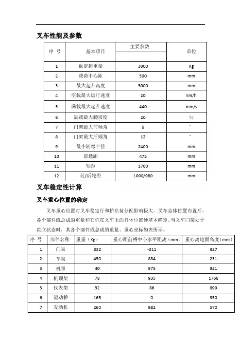
叉车性能及参数叉车稳定性计算叉车重心位置的确定叉车重心位置对叉车稳定行和桥负荷分配影响极大。
叉车总体位置布置后,各个部件或总成的重量和它们在叉车上的具体位置便基本确定。
当叉车门架处于直立状态时,其各个部件或总成的重量、重心坐标如表所示。
1.当叉车处于空载静止时,由力矩平衡可得下列公式:∑M x =g1 x1+g2 x2+⋯+g n x n=Gx0∑M y =g1 y1+g2 y2+⋯+g n y n=Gy0∑M z =g1 z1+g2 z2+⋯+g n z n=Gz0式中:g1,g2。
g n——叉车各部件重量(kg);x1,x2。
x n——各部件重心在叉车纵轴(x轴)方向至前桥中心的水平距离(mm)(在前桥中心以后为正,反之为负);y1,y2。
y n——各部件中心至地面的高度(mm);z1,z2。
z n——各部件中心至叉车纵向中心平面的水平距离,一边为正,另一边为负(mm);x0,y0,z0——叉车重心坐标(mm)。
由以上公式可得空载时的重心坐标:x0=∑M xG ,y0=∑M yG,z0=∑M zG由于各个部件对叉车纵向中心平面对称布置,致使∑M z 等于零。
将表格中的数据代入上述重心公式,可得:x0=∑M xG=42196704200mm=1010.4mmy0=∑M yG=26638524200mm=637.8mm2.码垛时的纵向稳定性(纵向静稳定性)叉车满载码垛,门架直立,货物起升到最大高度,如图所示。
其合成重心位置:a=GL0−Q(c+b)G+Qh g=Qh1+Gh2 G+Q式中:a——叉车合成重心至前桥中心线的水平距离;b——叉车合成中心至地面的垂直高度(b=1.4r前=1.4×355=497mm);c——载荷中心距(500mm);G——叉车自重(4200kg);Q——额定起重量(3000kg);L0——叉车自身重心至前桥中心线的水平距离(L0=x0=1010.4mm);h1——货物重心至地面的垂直高度(h1=H+c=3000+500=3500mm);h2——叉车自身重心至地面的垂直高度(h2=y0=637.8mm)。

伸缩臂叉装车总体结构设计摘要:伸缩臂叉装车已成为高空作业设备的重要门类,是广泛应用于建筑工地、工矿企业仓库和其他工地上起升、运输、堆放砖头、木材、钢材和其他物料的一种起重运输设备,随着经济建设的发展,对其需求越来越大,对其性能的要求也越来越高。
本文主要任务是完成对伸缩臂叉装车的总体计算、整体布局、臂架结构设计及其有限元分析。
本文主要内容:⑴介绍伸缩臂叉装车的用途、国内外伸缩臂叉装车发展状况的比较、及其发展前景。
同时对臂架的结构和工作原理做了简要介绍。
⑵完成对关键铰点的布置,作业高度、作业幅度的计算,及整机稳定性的校核计算。
并绘制出整机总体布局图。
⑶臂架的结构设计,臂架的强度、刚度和稳定性计算,并用ANSYS软件进行臂架有限元分析。
同时完成臂架系统装配图,一节臂、二节臂的装配图和相关零部件的工程图。
⑷设计过程采用Pro/E软件进行三维实体建模,并进行装配,最后应用其工程图模块转化为二维工程图。
本次设计的伸缩臂叉装车参考了JCB公司的JCB530型号伸缩臂叉装车的外形尺寸,并且严格按照《起重机金属结构》、《BS_EN_1459-1999》和《机械设计手册》等相关设计规范进行设计,其性能和质量满足相关要求。
关键词:伸缩臂叉装车;稳定性;臂架;有限元分析The Frame Structure Design of TelehandlerAbstract:Telehandler is a kind of hoisting equipment which is widely used in building site、storage and other place to lift、transport、stack the tile 、wood 、steel products and other materiel . Along with the development of economic in our country, the requirement of crawler crane is larger and larger, and the request of the capability is higher and higher.the mission of this paper is to complete the frame structure design of telehandler、the design of boom structure and the finite analysis of boom.The primary contents in this paper can be concluded as follows:The use of the telehandler、the telehandler’s development comparison domestic with abroad、and the development trend of the telehandler are introduced.At the same time,the paper introduces the structure of boom and how boom works, and gives the principle of how to choose the boom.The pivot points arrangment , the calculation of lift height and forward reach, and the calculation of the stability are completed.The integral layout drawing is provided.The structure design of the boom, the calculation of the strength and stability of the boom system are accomplished and the finite analys of boom is achieved by ANSYS software. While at the same time planar engineering drawing must be done, such as the assembling of the boom system, the boom one the boom two and the related parts.I use the Pro-E software to design the 3D entity, and make dummy assembly. And then, the 3D entity is transformed to the planar engineering drawing with the Pro/E planar engineering drawing module.In the design process, I refer to the JCB530 telehandler of JCB, and accord to the《Crane Metal Stuctrure》、《BS_EN_1459-1999》and the《Machine Design Handbook》strictly. Its capability and quality meet the requirement.Key Words:Telehandler;Stability;Boom;The Finite element analysis目录摘要 (I)ABSTRACT (II)绪论 (1)1伸缩臂叉装车概述 (1)1.1 伸缩臂叉装车简介 (1)1.2 国外伸缩臂叉装车发展状况 (1)1.3 国内伸缩臂叉装车发展状况 (2)1.4 国内伸缩臂叉装车的前景及发展趋势 (2)1.5 国内、外相关标准 (3)第一章毕业设计任务书 (4)1题目来源:实际应用 (4)2设计要求和设计参数 (4)2.1设计要求: (4)2.2设计参数: (4)3个人重点工作 (5)4各阶段时间安排 (5)5应阅读的资料及主要参考文献目录 (5)第二章毕业设计计算说明书 (5)1设计参数及整机尺寸 (5)1.1 设计参数 (6)1.2 整机尺寸 (6)2重要铰点布置及其计算 (7)3作业高度H计算 (8)4幅度R计算 (9)5整机稳定性计算 (9)5.1 整体稳定性计算工况和载荷 (9)5.2 整体稳定性结果汇总 (11)6臂架结构设计及其计算 (12)6.1 臂架结构设计 (12)6.2 臂架理论计算 (12)6.2.1 臂架全伸,仰角62时刚度、强度计算 (13)6.2.2臂架全伸,仰角0度时刚度、强度、稳定性计算 (24)6.3 各臂节支反力计算 (26)6.3.1 对臂架整体受力分析 (26)6.3.2 伸臂时各臂节支反力计算 (27)6.3.3 缩臂时各臂节支反力及缩臂链拉力 (29)第三章:标准化审验报告 (30)1技术分析 (30)2结论 (30)参考文献 (32)致谢 (33)绪论1 伸缩臂叉装车概述1.1 伸缩臂叉装车简介在高空作业类小型机械中,主要有高空作业平台、伸缩臂叉装车等种类。

太原科技大学本科毕业设计说明书设计题目:5吨叉车机械传动系统The Designing of Machinery Transmission System for 5 Ton Forklift学院:机械工程学院专业:机械设计制造及其自动化学生姓名:学号:指导教师:评阅教师:完成日期:2013年6月10日太原科技大学Taiyuan University of Science and Technology5吨叉车机械传动系统设计摘要:此次设计题目是五吨叉车机械传动系统设计。
内容主要包括五吨叉车发动机选择,离合器验算,变速器和驱动桥的设计与强度验算。
因为此次设计中绘图部分为变速器,所以说明书中更为侧重关于变速器的设计过程。
本次设计参考了众多关于叉车传动系统的书籍及计算案例,淘汰一些旧的设计方法,并且尽可能的做到创新设计。
为了精简篇幅,适应内容少而精的要求,有些方案介绍时,直接选取较为优越且合适的方案,不在赘述。
关键词:叉车,机械传动,变速器,驱动桥The Designing of Machinery Transmission System for 5 Ton ForkliftAbstract: this topic is about the designing of machinery transmission system for 5 ton forklift. Main content includes the choice of 5 ton forklift truck engine, and the check of clutch gearbox and drive axle. Because gearbox is put the important place in drawings , the instructions is more emphasis on the design of the gearbox.This design refers to a number of books about forklift drive system design and calculation. It phases out some old design methods, and does innovative design as soon as possible. In order to reduce space, adapt to the requirement of conciseness, this design will make direct selection that is more superior and suitable solutions in the introduces of some schemes.Key Words: forklift, the mechanical transmission, gearbox, drive axle前言本次设计题目是5吨叉车的机械传动系统,主要内容是发动机的选择,离合器的验算,变速器的设计和驱动桥的设计,其中变速器的设计是主要内容。


SQ6S伸缩臂式随车起重机设计计算书第一章概述SQ6S型随车起重机是以解放CA1165P1K2L2载重汽车为底盘,起重机直接安装在驾驶室和货箱之间的车架上,车架部分改装,动力以取力机构的形式从汽车发动机得到动力,各工作机构的动力皆来源于液压泵,在设计过程中,强调整车的性价比。
第二章整车稳定性的计算一、装后起重机作业的主要参数和起重性能表:表一二、底盘重心位置计算1.根据底盘技术参数可知如下参数:表二1.1各部件距回转中心的距离L(i)mm和各部件的重量G(i)Kg1.1.1吊勾总成L(1)=3940 G(1)=54.11.1.2 伸缩臂总成L(2)=1800 G(2)=723.41.1.3 起升机构L(3)=-55 G(3)=951.1.4 转台与齿轮柱焊接 L(4)=-30 G(4)=207 1.1.5 油箱安装总成 L(5)=-215 G(5)=36 1.1.6 固定支腿与活动支腿装配 L(6)=-270 G(6)=506.8 1.1.7 回转基座装配 L(7)=0 G(7)=120 1.1.8 基座与固定腿焊接 L(8)= 0 G(8)=165 1.1.9 操纵系统 L(9)=250 G(9)=40 1.1.10 液压系统 L(10)=200 G(10)=200 1.1.11 变幅油缸 L(11)=280 G(11)=120 1.1.12 其它 L(12)= 0 G(12)=70 1.2 吊机自重:G(S)=∑==121i i G(i)=2337 Kg1.3 吊机重心距回转中心距离:L1 =∑==121i i G(i)⨯L(i)/ G(S)=620 mm2. 吊机在全伸状态时的重心计算 2.1 各部件距回转中心的距离L2(i)mm经分析可知:只有吊勾和伸缩臂总成的重心发生变化2.1.1 吊勾总成 L2(1)=9240 2.1.2 伸缩臂总成 L2(2)=4000 2.2 吊机重心距回转中心距离:L1 =∑==121i i G(i)⨯L(i)/ G(S)=1421 mm3. 吊机在行驶状态下的桥荷分布:根据上述计算全缩时吊机重心距回转中心距离为620mm 。
叉车计算公式汇总Forklifts are an essential tool in many industries, used for lifting and transporting heavy loads. In order to operate a forklift safely and efficiently, it is important to understand the different formulas involved in calculating various aspects of its performance. These formulas can help operators determine load capacity, tipping points, and other critical factors that affect the safe operation of the forklift.叉车在许多行业中是必不可少的工具,用于提升和运输重物。
为了安全高效地操作叉车,了解计算叉车性能各方面的不同公式是很重要的。
这些公式可以帮助操作员确定叉车的载荷能力、翻转点和其他影响叉车安全操作的关键因素。
One of the most important formulas for forklift operators to understand is the load capacity formula, which is used to determine the maximum weight that a forklift can safely lift. This formula takes into account the weight of the load, the load center, and the capacity of the forklift. By using this formula, operators can avoid overloading the forklift, which can lead to accidents and injuries.叉车操作员需要了解的最重要的公式之一是载荷容量公式,该公式用于确定叉车可以安全提升的最大重量。
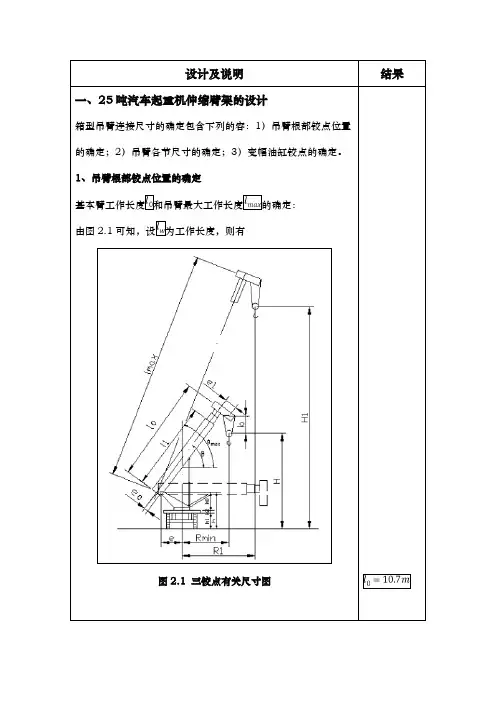
设计及说明 一、25 吨汽车起重机伸缩臂架的设计箱型吊臂连接尺寸的确定包含下列的容:1)吊臂根部铰点位置 的确定;2)吊臂各节尺寸的确定;3)变幅油缸铰点的确定。
1、吊臂根部铰点位置的确定 基本臂工作长度 和吊臂最大工作长度 的确定: 由图 2.1 可知,设 为工作长度,则有结果图 2.1 三铰点有关尺寸图式中:H—基本臂的起升高度,。
b—吊钩滑轮组最短距离,取。
、 —根部铰点和头部滑轮轴心离吊臂基本截面中心线的距离,并带有符号。
由于 以计算时可以忽略不计。
此项数值较小,所—吊臂仰角,取。
h—根部铰接点离地距离,取。
吊臂根部离铰点的距离 e—最小工作幅度,取。
吊臂根部铰点离回转平面的高度—回转支承装置的高度, —起重机汽车底盘的高度, 主吊臂最大长度—最长主臂起升高度, a,r,b,h 同上。
2、吊臂各节尺寸的确定主吊臂的最长长度 成。
是由基本臂结构长度和外伸长度 所组、 、 —各节臂的伸缩长度,在设计中伸缩长度往往取同一数值,即 。
外伸长度。
、 、 —为二、三、四节臂缩回后外漏部分的长度,在计算时取同一数值(a=0.25m)若假设 为臂头滑轮中心离基本臂端面的距离,则基本臂结构长 度加上 即为基本臂的工作长度。
所以有从中可以求出k—吊臂的节数。
—主臂最大长度,初取 35m。
—主臂最小长度,初取 11m。
通常搭接长度应该短些,以减轻吊臂重量。
但是,太短将搭接部 分反力增大了,引起搭接部分吊臂的盖板或侧板局部失稳,同时, 也使吊臂的间隙变形增大。
因此搭接部分要根据实际经验和优化设计而定,一般为伸缩臂外伸长度的 1/4—1/5(吊臂较长者取 后者,较短者取前者,同步伸缩者可取后者)。
从而搭接长度 为在第 i 节臂退回后,除外露部分长度 a 外,在前节(i-1)节臂中 的长度 加上伸出后仍在前节臂中的那部分搭接长度 。
第 i 节臂 插在前节臂的长度为( ),设第 i 节臂的结构长度为 ,则各节伸缩臂插入前一节都留有一段距离 c,这是结构的需要,在 此距离要设置伸缩油缸的铰支座和其他的结构构件,其大小视情 况而定,在此次设计中选择 c=0.35m。
伸缩臂叉车伸缩臂强度测试及臂架间摩擦因数计算研究摘要:伸缩臂叉车是现代化工业运输之中的常用工具,其主要的受力部位为该机械伸缩臂的臂架,本文首先阐述了伸缩臂叉车伸缩臂受力强度的分析方法,进一步对伸缩臂叉车伸缩臂架的受力强度进行了计算,最后依照前期所计算的结果,对伸缩臂叉车摩擦因数进行了试验分析,以期能够为相关设计人员,提供参考。
关键词:伸缩臂;叉车;强度测试;摩擦因数前言:伸缩臂叉车与普通叉车的区别在于,其是具备一定越野性能带伸缩机械臂的多用途设备,当前市面上的伸缩臂叉车荷载能力大概在0—4.5吨范围之内,具有较强的搬运输送能力,被广泛应用于建筑工地、工业企业、农畜企业之中,其主要的受力性能与伸缩臂的强度与摩擦因数有关,因此需要对其加大研究。
1伸缩臂叉车伸缩臂受力强度分析方法1.1受力强度分析原理在分析伸缩臂叉车的伸缩臂受力强度时,首先要了解其基本结构以及影响其受力的主要因素。
当前伸缩臂的截面形状、材料以及受力点,是影响其受力强度的主要因素。
而其中伸缩臂的截面形状也有多种分类形式,如矩形、U型等,本文所研究的案例车型为国内某公司所研发的TH844A型伸缩臂叉车。
叉车前端的伸缩臂共由三节部件所组成,界面形状为腹板与翼缘板所焊接的矩形。
由于,先前已经确定了伸缩臂界面以及其所使用的材料,因此就能深入地分析其荷载能力,同时在伸缩臂伸缩的过程中,相关技术人员也不得不考虑其所产生的摩擦因数,由于该因数会决定伸缩臂伸缩液压缸的选型设计,因此需要对其加大计算。
目前在伸缩臂叉车受力分析方法上有两种,一是结合伸缩臂加载受力部位依照给定材料特性,结合截面形状,求出伸缩臂的整体承载能力。
二是通过加载伸缩臂的方式,来测验伸缩油缸的压力,并对其各个部位的受力情况进行分析,最终得出整体伸缩臂的承载能力。
由于第一种方法存在无法分析伸缩臂危险截面缺陷的问题,且操作难度较高,因此本文则选择第二种方式进行分析[1]。
1.2伸缩臂受力的分析常规伸缩臂叉车伸缩臂的主要受力结构可以分为三个层次,其中第三节以及第二节臂是叉车伸缩臂的主要受力区,一、二、三节臂的受力主要取决于机械链条的拉力,受自身重力与荷载能力、摩擦力、臂间支反力的影响。
2.0吨叉车工作装置液压系统设计1 提升装置的设计根据设计条件,要提升的负载为2100kg,因此提升装置需承受的负载力为:N为减小提升装置的液压缸行程,通过加一个动滑轮和链条(绳),对装置进行改进,如图1所示。
图1 提升装置示意图由于链条固定在框架的一端,活塞杆的行程是叉车杆提升高度的一半,但同时,所需的力变为原来的两倍(由于所需的功保持常值,但是位移减半,于是负载变为原来的两倍)。
即提升液压缸的负载力为2 Fl = 41200 N如果系统工作压力为100bar,则对于差动连接的单作用液压缸,提升液压缸的活塞杆有效作用面积为m2所以活塞杆直径为d = 0.0724 m,查标准(63、70、80系列),取 d = 0.070m。
根据液压缸的最大长径比20:1,液压缸的最大行程可达到1.40 m,即叉车杆的最大提升高度为2.80 m,能够满足设计要求的2 m提升高度。
因此,提升液压缸行程为1m,活塞杆和活塞直径为70/100mm(速比2)或70/125mm(速比1.46)。
因此活塞杆的有效作用面积为m2当工作压力在允许范围内时,提升装置最大流量由装置的最大速度决定。
在该动滑轮系统中,提升液压缸的活塞杆速度是叉车杆速度(已知为0.2m/s)的一半,于是提升过程中液压缸所需最大流量为:m3/sl/min2 系统工作压力的确定系统最大压力可以确定为大约在110bar左右,如果考虑压力损失的话,可以再稍高一些。
3 倾斜装置的设计倾斜装置所需的力取决于它到支点的距离,活塞杆与叉车体相连。
因此倾斜液压缸的尺寸取决于它的安装位置。
安装位置越高,即距离支点越远,所需的力越小。
图2 倾斜装置示意图假设r =0.5m,倾斜力矩给定为T =7500 N.m,因此倾斜装置所需的作用力F 为:N如果该作用力由两个双作用液压缸提供,则每个液压缸所需提供的力为7500N。
如果工作压力为100bar,则倾斜液压缸环形面积Aa为:m2由于负载力矩的方向总是使叉车杆回到垂直位置,所以倾斜装置一直处于拉伸状态,不会弯曲。
伸缩臂叉车工作装置设计
本课题是企业根据市场对于对高举升、大卸距、一机多能的装载机械日趋迫切的需求而进行的产品研发项目。
要求产品达到国外同类产品的性能水平。
考虑到伸缩臂叉车须达到额定的载荷、较大的变幅角度、较大的作业幅度、各种复杂的作业环境以及伸缩臂叉车所必须满足的安全性能,需在设计中对伸缩臂叉车作业装置进行严谨的设计计算以满足产品的使用性能。
论文主要内容如下:1.简要介绍伸缩臂叉车的用途、国内外伸缩臂叉车发展状况、及其发展前景,同时对臂架结构和工作原理进行说明,为伸缩臂叉车工作装置设计做铺垫。
2.应用质量屋工具将用户的需求转换为产品技术需求,得到零部件的技术性能指标,并以此为参照进行总体设计,包括整体布局规划、作业范围计算、核心零部件选型,以及确定电气、液压、传动系统的设计思路。
3.伸缩臂叉车工作装置详细设计,包括货叉和臂架结构设计、臂架强度、刚度和稳定性计算、货叉平动功能设计、整机稳定性校核计算等。
4.采用Pro/E软件中的TOP-DOWN设计方法,实现伸缩臂叉车的三维实体造型设计、虚拟装配和干涉检验,并将三维模型转换为二维工程图。
使用Mechanica 模块,对伸缩臂进行有限元分析,找出薄弱环节,做出改进设计。
通过产品试制后,该产品完全达到了预期目标,性能完善且工作可靠,具有良好的市场潜力和推广应用价值。
高性价比的伸缩臂叉车
佚名
【期刊名称】《叉车技术》
【年(卷),期】2005(000)002
【摘要】美国Carelift公司声称其新品ZB10056型伸缩臂叉车是同级产品中最低价的。
该机采用了“单侧壁机架”降低了司机室进出的高度,并将发动机置于中部。
ZB10056系列包含6个机型,举升能力2727~9091kg,举升高度9.76~17m。
【总页数】1页(P18)
【正文语种】中文
【中图分类】U216.6
【相关文献】
1.伸缩臂叉车伸缩臂强度测试及臂架间摩擦因数的计算 [J], 田甜;王志;闫洪峰
2.基于HyperWorks的伸缩臂叉车伸缩臂结构拓扑优化 [J], 王佑君;胡犇;侯忠明;
王胜军;王有才
3.高速伸缩臂叉车传动系统设计计算 [J], 王勇
4.高速伸缩臂叉车整体车架受力分析 [J], 王勇; 王丹; 刘珂
5.伸缩臂叉车臂架计算协同设计平台 [J], 梁爽;洪海生;付大明
因版权原因,仅展示原文概要,查看原文内容请购买。