《中文版SolidWorks-2014案例教程》很好
- 格式:ppt
- 大小:5.24 MB
- 文档页数:92
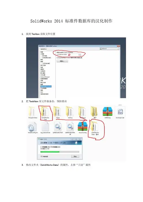
SolidWorks 2014 标准件数据库的汉化制作1.找到Toolbox读取文件位置
2.把Tooblbox原文件做备份,预防错误
3.修改文件夹《SolidWorks Data》的属性,去掉“只读”属性
4.在SolidWorks操作界面右侧,点击“设计库”
5.点击,可看到下图
6.进入可看到下图
7.进入可看到下图
8.进入可看到下图
9.把拖入SolidWorks操作界面,可看到下图
10.点击左上角,进入“属性”
11.编辑属性,输入代号< GB/T 6176-2000>,点击保存,关闭零件
12.进入选项进入界面
13.点击进入界面
14.点击进入界面
15.点击进入界面
16.点击进入界面
17.点击进入界面
18.点击进入界面
19.点击进入界面,一定要和开始编辑的是同一个零件
20.点击添加<名称> , 确定
21.进入界面后选取<名称> ,可见界面,多出<名称> 空连,如图
22.点击右面输出数据,保存
23.编辑保存的xis 文件,全选下的所有
文字
复制到
24.修改名称《GB_HEXAGON_TYPE10_1》为《2型六角螺母细牙》,如下图
25.
26.全选复制到第1连的下,如图
保存,退出;
27.回到Toolbox界面,点击输入数据,输入
刚才修改的xls 文件,输入完成,<名称> 连填充完成,如图
点击保存,关闭,汉化完成
28.回界面
去掉选项
,防止SolidWorks读取默认的标准件位置。
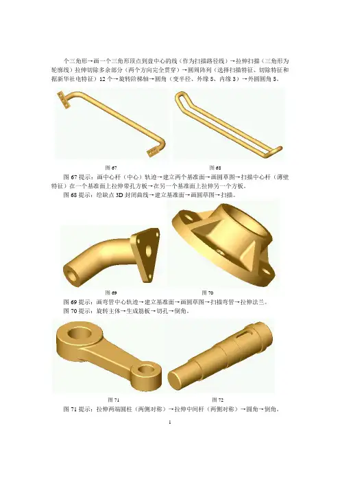
个三角形→画一个三角形顶点到盘中心的线(作为扫描路径线)→拉伸扫描(三角形为轮廓线)拉伸切除多余部分(两个方向完全贯穿)→圆周阵列(选择扫描特征、切除特征和据新华社电特征)12个→旋转阶梯轴→圆角(变半径、外缘5、内缘3)→外圆圆角5。
图67 图68图67提示:画中心杆(中心)轨迹→建立两个基准面→画圆草图→扫描中心杆(薄壁特征)在一个基准面上拉伸带孔方板→在另一个基准面上拉伸另一个方板。
图68提示:绘缺点3D封闭曲线→建立基准面→画圆草图→扫描。
图69 图70图69提示:画弯管中心轨迹→建立基准面→画圆草图→扫描弯管→拉伸法兰。
图70提示:旋转主体→生成筋板→切孔→倒角。
图71 图72图71提示:拉伸两端圆柱(两侧对称)→拉伸中间杆(两侧对称)→圆角→倒角。
12图72提示:旋转轴→建立基准面→切除键槽。
图73 图74图73提示:旋转主体→切横孔→切阶梯孔。
图74提示:旋转主体→切孔。
图75 图76 图75提示:旋转。
图76提示:拉伸侧板→拉伸底板→拉伸圆柱→盘板→切孔。
图77 图78图77提示:拉伸底板→建立基准面→拉伸斜圆柱→切孔。
图78提示:拉伸底板→拉伸上部→抽壳→拉伸法兰→切孔。
3图79 图80图79提示:旋转→切孔。
图80提示:拉伸底板→拉伸底板凸台→拉伸圆柱→拉伸侧圆柱→切中孔→切横孔→切底板孔。
图81 图82图81提示:拉伸中间圆套→切键槽→旋转一个手把→阵列。
图82提示:拉伸大板→拉伸半圆体→旋转中间圆柱→拉伸小板→切中孔→切方槽。
图83 图84图83提示:右侧板→拉伸侧圆柱→切侧圆柱孔→拉伸上板→拉伸上小板体→切小板中间部分→切小板孔→拉伸上圆柱→切上圆柱孔。
图84提示:拉伸主体→拉伸底板→拉伸上沿→拉伸一侧轴承座圆柱→加筋板→拉伸固定板→切轴承孔→切轴承压盖孔→镜象另一半→切底板孔→切连接孔→生成分隔线→拔模固定板。
4图85 图86图85提示:拉伸主体→圆角主体→抽壳主体→拉伸底沿→拉伸侧固定板→拉伸一侧轴承座→切一侧轴承孔→拉伸固定板→拔模固定板→加轴承压盖孔→加筋板→镜象另一半→拉伸顶部圆柱→切顶部小孔→切底板孔。
solidworks2014钣金设计实例精解英文版SolidWorks 2014 Sheet Metal Design Example ExplainedSolidWorks 2014, a powerful CAD software, has been widely used in various industries for its user-friendly interface and robust design capabilities. Among its many features, sheet metal design stands out as a particularly useful tool for engineers and designers. In this article, we will explore an example of sheet metal design in SolidWorks 2014, providing a detailed breakdown of the steps involved.Step 1: Creating a New PartTo begin, we need to create a new part in SolidWorks. This can be done by selecting "New" from the File menu and choosing "Part" as the document type.Step 2: Sketching the Base ProfileOnce the new part is created, we can proceed to sketch the base profile of our sheet metal component. This involvesdefining the shape and dimensions of the part using the Sketch tools provided in SolidWorks. For this example, let's assume we are designing a simple bracket.Step 3: Defining the MaterialBefore we can proceed with the sheet metal design, we need to specify the material for our part. This can be done by selecting the "Material" property in the PropertyManager and choosing the desired material from the list. For this example,let's use aluminum.Step 4: Converting to Sheet MetalWith the base profile sketched and the material defined, we can now convert the part to sheet metal. This can be done by selecting the "Convert Entities" feature in the FeatureManager design tree and choosing "Sheet Metal" as the conversion type.Step 5:Applying BendsOnce the part is converted to sheet metal, we can start applying bends to create the desired shape. SolidWorks provides various bending tools that allow us to create accurateand realistic bends based on the material properties. For this example, we will use the "Base-Flange" bend to create the bracket's shape.Step 6: Refining the DesignAfter applying the bends, we can refine the design by adding additional features or modifying the existing ones. SolidWorks allows us to easily add cutouts, fillets, and other features to improve the part's functionality and aesthetics.Step 7: Saving the PartFinally, once the design is complete, we can save the part by selecting "Save" from the File menu. It is also a good practice to save the part periodically throughout the design process to avoid data loss.In conclusion, SolidWorks 2014 provides a powerful and user-friendly platform for sheet metal design. By following the steps outlined in this article, engineers and designers can create accurate and realistic sheet metal components with ease. Thesoftware's robust design capabilities and intuitive interface make it an ideal choice for sheet metal design applications.中文版SolidWorks 2014钣金设计实例精解SolidWorks 2014是一款功能强大的CAD软件,因其用户友好的界面和强大的设计功能,广泛应用于各个行业。


工程图设计SolidWorks提供了生成完整的详细工程图的工具。
同时工程图是全相关的,当修改图纸时,三维模型、各个视图、装配体都会自动更新,也可从三维模型中自动产生工程图,包括视图、尺寸和标注。
工程图的绘制方法绘制视图编辑工程视图视图显示控制标注尺寸打印工程图机械臂装配工程图任务驱动&项目案例Note图11-1 “新建SolidWorks文件”对话框)单击“确定”按钮,关闭该对话框。
)在弹出的“图纸格式/大小”对话框中选择图纸格式,如图11-2所示。
标准图纸大小:在列表框中选择一个标准图纸大小的图纸格式。
自定义图纸大小:在“宽度”和“高度”文本框中设置图纸的大小。
如果要选择已有的图纸格式,则单击“浏览”按钮导航到所需的图纸格式文件。
)在“图纸格式/大小”对话框中单击“确定”按钮,进入工程图编辑状态。
项目图标旁边的符号Note图11-2 “图纸格式/大小”对话框图11-3 工程图窗口标准视图包含视图中显示的零件和装配体的特征清单。
派生的视图(如局部或剖面视图)包含不同的特定视图项目(如局部视图图标、剖切线等)。
工程图窗口的顶部和左侧有标尺,标尺会报告图纸中光标的位置。
选择菜单栏中的尺”命令,可以打开或关闭标尺。
Note 格式。
设计树中的“图纸格式”按钮。
图11-4 “注释”属性管理器)如果要移动线条或文字,单击该项目后将其拖动到新的位置。
)如果要添加线条,则单击“草图”工具栏中的“直线”按钮,然后绘制线条。
FeatureManager设计树中右击“图纸”按钮,在弹出的快捷菜单中选择“属性”命令。
)系统弹出的“图纸属性”对话框如图11-5所示,具体设置如下。
图11-5 “图纸属性”对话框·332·。