HP NC364T PCI Express 四端口千兆位服务器适配器
- 格式:pdf
- 大小:599.09 KB
- 文档页数:20

HP t640 Thin ClientFRONTBACK1 Power button (with integrated power indicator) 1 (2) USB-A 3.1 Gen 1 port2 Flash memory activity indicator 2 (3) DisplayPort ™1.2 digital video outputs3 (1) USB-A 3.1 Gen 1 port 3 19V DC power input4 (1) USB-A 3.1 Gen 2 port 4 Cable lock slot5 (1) USB-C ™ 3.1 Gen 2 port 5Configurable Option Port supporting one of the following: • Blank; no optional configured port • 2 x USB-A 3.1 Gen 1 ports• DisplayPort ™ over USB-C ™ with USB Power Delivery • HDMI digital video output • VGA analog video output• External Wi-Fi antenna connector • Fiber Optic NIC connectors (SC or LC)• Serial port with configurable power (shown) • Dual serial ports (includes cable adapter) 6 3.5 mm combo headset/audio jack7 Access panel to information labels and VESA 100 mounting holes 8System stand 6 3.5 mm audio jack 7 (1) USB-A 2.0 port 8 (1) USB-A 2.0 port(designated for Power-on with Keyboard if equipped) 9 RJ45 GbE network connector10Rear I/O cover removal latchAT A GLANCE•AMD Ryzen R1505G System-on-Chip; 2.4 – 3.3 GHz; 2 cores, 4 threads3•AMD Memory Guard Secure Run technology that encrypts data in main memory•DDR4 dual-channel SDRAM system memory; up to 2400 MT/s transfer rate; two SODIMM slots•(3) DisplayPort 1.2 video outputs supporting up to UHD/4K (3840 x 2160 @ 60 Hz) resolutionsNOTE: DisplayPort cables and displays sold separately.•Solid-state flash memory storage; M.2 form factor modules; one slot•Gigabit Ethernet (GbE) network connection; support for DASH out-of-band remote management•Optional Allied Telesis M.2 Fiber Optic NICs; Fast Ethernet (100 Mb/s) or Gigabit (1,000 Mb/s)•Optional Intel Wireless-AC 9260 Wi-Fi/Bluetooth® adapter including antennas integrated internally in the chassis NOTE: Fiber optic and Wi-Fi NIC options cannot be supported together1NOTE: Wireless features, performance and support may vary depending on environmental variables such placement, settings andfirmware of your access points. Please contact your wireless vendor for support of your wireless environment•Optional remote external Wi-Fi antenna system•Option Port with a selection of available factory options (see detailed listing later in this document)•Integrated PC speaker for basic audio playback; 3.5 mm combo headset/audio port on front and 3.5 mm audio port on rear that can be configured as line in or line out supporting headphones, external speaker systems, or microphone•45W non-PFC external power adapter•Security features include a TCG certified TPM version 2.0 and a system UEFI (BIOS) designed to address NIST SP 800-147 BIOS protection guidelines and NIST SP800-155 BIOS integrity measurement guidelines. A cable lock slot is provided for use with a cable lock to enable the system’s physical security•Passive thermal design (no cooling fans) and active thermal management technology that monitors the system operating temperatures, throttles SOC operation if appropriate and prevents unit thermal shutdown.•Rated for a maximum ambient operating temperature of 40 degree C•ENERGY STAR® certified configurations available and EPEAT® Silver registered in the United States (except for some models configured with Fiber Optic NIC networking options). See for registration status in other countries •Post-consumer recycled plastics content greater than 25% total unit plastics (by weight)•Low halogen2material content•All models TAA compliant in North America1 Wireless access point and Internet access is required; availability of public wireless access points is limited2 This product is low halogen except for power cords, cables and peripherals, as well as the optional Fiber Optic NIC module; service parts obtained aftermarket may not be low halogen3 Multicore is designed to improve performance of certain software products. Not all customers or software applications will necessarily benefit from use of this technology. Performance and clock frequency will vary depending on application workload and your hardware and software configurations. AMD’s numbering is not a measurement of clock speedWarrantyHP Customer Support: limited three-year hardware limited warranty in most regions; HP Care Packs are extended service contracts that go beyond your standard limited warranties; for more details visit /go/cpcOPERATING SYSTEMS•HP ThinPro, including HP /Smart Zero Core •Windows 10 IoT Enterprise LTSC 2021 •Windows 10 IoT Enterprise LTSC 2019•IGELPROCESSORModel CPU FrequencyMax/BaseCores/Threads GPU Type GPU FrequencyAMD Ryzen R1505G 3.3/2.4 GHz2/4 Radeon Vega 3 1000 MHzDISPLAY SUPPORTNumber of displays supported A maximum of 3 displays are supported.Combination:3 x DisplayPort(onboard)2 x DisplayPort(onboard) + 1 x DisplayPort over USB-C(optional)2 x DisplayPort(onboard) + 1 x HDMI(optional)2 x DisplayPort(onboard) + 1 x VGA(optional)Video outputs 3 x DisplayPort(onboard)2 x DisplayPort(onboard) + 1 x DisplayPort over USB-C(optional)Video Resolution Support MatrixGRAPHICSNumber of displays supported: 3Video outputs: Standard: (3) DisplayPort™ 1.2Optional: (1) DisplayPort™ over USB-C™ with USB Power Delivery(1) VGA analog output(1) HDMI digital outputNOTE: adding and optional output does not increase the number of displays supported.Max. screen resolution: 3840 x 2160 @ 60 HzNOTE: HP recommends dual channel memory (two SODIMMs) configurations for optimal display resolution performanceMEMORYType: DDR4 dual channel SDRAMData Transfer Rate: Up to 2,400 MT/sPeak Transfer Rate: Up to 19,200 MB/sNumber of Slots 2 x SODIMMCapacities: 4, 8, 16 and 32 GBNOTES:•The actual transfer rates will be dependent upon the specification of the SODIMM modules used•The Graphics Processing Unit (GPU) uses part of the total system memory. System memory dedicated to graphics performance is not available for use by other programs•HP recommends dual channel memory (two SODIMMs) configurations for optimal system performanceUEFIUEFI Specification Revision 2.3.1TPM 2.0Meets requirements for Common Criteria, an independent third-party certification oftrustworthinessMeets requirements for FIPS 140-2, a standard for cryptographic integritySecurity features System UEFI designed to address NIST SP 800-147 BIOS protection guidelines and NIST SP800-155 BIOS integrity measurement guidelinesSTORAGEType: NAND flash memory; non-volatileNumber of Sockets: (1) M.2Capacities: 16 GB M.2 eMMC flash module32 GB M.2 eMMC flash module64 GB M.2 eMMC flash module128 GB M.2 SATA flash module256 GB M.2 NVMe flash module512 GB M.2 NVMe flash moduleInput/OutputUSB: Front access: (1) USB-A 3.1 Gen 1 port(1) USB-A 3.1 Gen 2 port(1) USB-C™ 3.1 Gen 2 portRear access: (1) USB-A 2.0 port(1) USB-A 2.0 port (designated for Power-on from Keyboard if equipped)(2) USB-A 3.1 Gen 1 ports(2) USB-A 3.1 Gen 1 ports (optional)Video Outputs: Standard: (3) DisplayPort™ 1.2 digital outputsOptional: (1) VGA analog output(1) HDMI digital output(1) DisplayPort™ over USB-C™ with USB Power DeliveryNOTE: adding an optional output does not increase the number of displays supported.I/O Interfaces: Standard: (1) RJ45 network connector(1) 3.5 mm combo headset/audio jack (front)(1) 3.5 mm audio jack (rear)Optional: (1) serial port with configurable power(2) serial ports enabled with an included cable adapterOption Port: The rear I/O panel includes an Option Port that can be configured with one of the following factory options:•Blank; no optional configured port• 2 x USB-A 3.1 Gen 1 ports•DisplayPort™ over USB-C™ with USB Power Delivery•HDMI digital video output•VGA analog video output•External Wi-Fi antenna connector (requires Wi-Fi adapter option)•Fiber Optic NIC connectors; SC or LC connector (requires Fiber Optic NIC option)•Serial port with configurable power•Dual serial ports enabled with an included cable adapterAUDIO/VIDEOAudio Subsystem •Internal amplified speaker system for basic audio playback• 3.5 mm combo headset/headphone/analog microphone audio jack (front access)• 3.5 mm combo line-out/ line-in socket (rear access)Audio CODECs •MP3•AAC Stereo•HE AAC•Includes hardware acceleration supportVideo CODECs •MPEG-4 part 2 (DivX, Xvid)•MPEG-4 part 10 (H.264, AVC), Advanced Video Coding (AVC) (H.264 encode & decode )•MPEG-H part 2, High Efficiency Video Coding (HEVC, available with Windows 10 IoT Only) (H.265 (8-bit / 10-bit) decode and (8-bit) encode•WMV 7/8/9 VC-1 & ASF Demuxer•Includes hardware acceleration supportNETWORKINGLocal Area Networking Realtek RTL8111EPH-CG Gigabit Ethernet (GbE) Controller with support for DASH out-of-band remote managementWi-Fi Networking Intel® Wireless-AC 9260 Wi-Fi/Bluetooth® combo; 2x2 802.11ac Wi-Fi and Bluetooth 5Intel® Wireless ax200 wifi 6Realtek 8852AE Wi-Fi6 +BT5.2 WLANNOTES: Wireless access point and internet access required. Availability of public wireless access points limited Wireless features, performance and support may vary depending on environmental variables such placement, settings and firmware of your access points. Please contact your wireless vendor for support of your wireless environmentFIBER OPTIC NETWORKINGAdapter Options: •Allied Telesis AT-27M2/SC Fiber Fast Ethernet M.2 Adapter•Allied Telesis AT-29M2/SC or LC Fiber Gigabit M.2 AdapterFeatures: •IEEE 802.1p priority encoding/tagging (QoS, CoS)•IEEE 802.1q VLAN tagging•IEEE 802.3x flow control•Buffer/FIFO: 2K transmit and 2K receive (AT-27M2)•Buffer/FIFO: 22K transmit and 40K receive (AT-29M2)•Loopback mode•Descriptor-Based Buffer Management•Wake-on-LAN from S3 (Sleep) and S4 (Hibernate) not supported•Link Detection and PHY interface power; the PHY interface, Link detection and Link LED should beenabled by default at power-upPerformance: AT-27M2 •>= 85 Mbit/s receive, <= 30% CPU utilization•>= 85 Mbit/s transmit, <= 30% CPU utilization•>= 170 Mbit/s total bi-directional, <= 30% CPU utilizationNOTE: The minimum transfer size at 100 Mbit/s is 1 GbpsAT-29M2 •>= 800 Mbit/s receive, <= 30% CPU utilization•>= 800 Mbit/s transmit, <= 30% CPU utilization•>= 1500 Mbit/s total bi-directional, <= 30% C:U utilizationNOTE: The minimum transfer size at 1000 Mbit/s is 1500 Gbps External Interface: Complies with IEEE 802.3 1000BASE-X operationPower: •Uses less than 1775 mW of power at full performance (AT-27M2)•Uses less than 2100 mW of power at full performance (AT-29M2)•Supports all PCI Express bus states L0, L0s, L1 and L2Non-volatile Storage: The MAC address is unique for each system; assigned from the board assembly manufacturer’s IEEE registered allocation.The PCI subsystem ID is unique to HP and unique to each design to allow Windows Update to be finely controlled.SOFTWARE SUPPORTperformance and support may vary depending on customer environment and backend.WEIGHTS & DIMENSIONSW x D x H:35 x 196 x 196 mm(vertical orientation)Volume: 1.34 literSystem Weight994.5g(unit with stand)Shipping Weight 2878gNOTE: All measurements are approximate; the addition of optional modules will increase the weightEXTERNAL POWER SUPPLY45W non-PFC Smart external power adapterWorldwide auto-sensing 100 - 240 VAC; nominal voltage is 120 VAC; 50 - 60 HzEnergy saving automatic power-down; surge tolerant1.8m output cableExternal power adapters are sourced from several suppliers in order to ensure adequate supply and availability is maintained. The actual dimensions of the power brick will vary by supplier.HP P/N Vendor Dimensions:L25296-001 Lite-On 94 x 40 x 26.5 mmL25296-002 Chicony 95 x 40 x 26.5 mmL25296-003 Delta 94 x 39 x 26.5 mmL25296-004 AcBel 91.4 x 44 x 26.8 mmCOMPLIANCE/CERTIFICATIONSAccessibility: Section 508 Accessibility; VPAT report available.Environmental Stewardship: Worldwide (ENERGY STAR® configurations available, EPEAT 2.0, RoHS2, ERP, TCO Certified, CECP& SEPA, HP GSE, WEEE, Low Halogen, etc.)Product Safety: Worldwide (UL, CB, GS, CCC, BSMI, etc.)Electromagnetic Compliance (EMC): Worldwide (FCC/CISPR/EN/VCCI/ICES/AS/NZS/CNS/KCC) “Class B” EMI regulations International Medical Safety Standard: EN60601-1-2 (Medical Equipment EMC)ENVIRONMENTALOperating Temperature Range: 50° to 104° F 10° to 40° CNon-operating Temperature Range: -22° to 140° F -30° to 60° CHumidity: Condensing: 20% to 80% Non-condensing: 10% to 90%NOTE: Specifications are at sea level with altitude derating of 1° C/300m (1.8° F/1000ft) to a maximum of 3 Km (10,000 ft), with no direct, sustained sunlight. Upper limit may be limited by the type and number of options installed.Basic Configuration (does not include a fiber optic NIC):Energy Consumption115 V ac, 60 Hz 230 V ac, 50 Hz 100 V ac, 60 Hz Normal Operation (Short idle) 9.35 W 9.62 W 9.43 WNormal Operation (Long idle) 8.45 W 8.62 W 8.52 WSleep 1.87 W 1.88 W 1.88 WOff 1.85 W 1.71 W 1.71 WHeat Dissipation* 115 V ac, 60 Hz 230 V ac, 50 Hz 100 V ac, 60 Hz Normal Operation (Short idle) 32 BTU/hr 33 BTU/hr 32 BTU/hr Normal Operation (Long idle) 29 BTU/hr 29 BTU/hr 29 BTU/hrSleep 6 BTU/hr 6 BTU/hr 6 BTU/hrOff 6 BTU/hr 6 BTU/hr 6 BTU/hr NOTE:Heat dissipation is calculated based on the measured watts, assuming the service level is attained for one hour.System configuration includes: HP Thin Pro 64bit operating system, 128 GB storage, 32 GB system memory, USB keyboard & mouseOptional Configuration (includes a fiber optic NIC):Energy Consumption115 V ac, 60 Hz 230 V ac, 50 Hz 100 V ac, 60 Hz Normal Operation (Short idle) 10.9 W 11.19 W 11.13 W Normal Operation (Long idle) 9.55 W 10.35 W 10.09 WSleep 2.99 W 2.98 W 3.02 WOff 2.84 W 2.81 W 2.85 WHeat Dissipation* 115 V ac, 60 Hz 230 V ac, 50 Hz 100 V ac, 60 Hz Normal Operation (Short idle) 37 BTU/hr 38 BTU/hr 38 BTU/hr Normal Operation (Long idle) 33 BTU/hr 35 BTU/hr 34 BTU/hr Sleep 10 BTU/hr 10 BTU/hr 10 BTU/hrOff 10 BTU/hr 10 BTU/hr 10 BTU/hr NOTE:Heat dissipation is calculated based on the measured watts, assuming the service level is attained for one hour.System configuration includes: Windows 10 IoT Enterprise LTSC operating system, 128 GB storage, 32 GB system memory, 100 Mbps SC Fiber Optic NIC, USB keyboard & mouseSummary of Changes© 2023 HP Development Company, L.P. The information contained herein is subject to change without notice. The only warranties for HP products and services are set forth in the express limited warranty statements accompanying such products and services. Nothing herein should be construed as constituting an additional warranty. HP shall not be liable for technical or editorial errors or omissions contained herein. AMD and Radeon are trademarks of Advanced Micro Devices, Inc. DisplayPort™and the DisplayPort™ logo are trademarks owned by the Video Electronics Standards Association (VESA®) in the United States and other countries. Amazon Web Services, the “Powered by Amazon Web Services” logo, and Amazon WorkSpaces are trademarks of , Inc. or its affiliates in the United States and/or other countries. Bluetooth® is a trademark owned by its proprietor and used by HP Inc. under license. ENERGY STAR is a registered trademark owned by the U.S. Environmental Protection Agency. Linux® is the registered trademark of Linus Torvalds in the U.S. and other countries. Microsoft and Windows are either registered trademarks or trademarks of Microsoft Corporation in the United States and/or other countries. Intel® is a trademark of Intel Corporation in the U.S and other countries. VMware Horizon and VMware Horizon View are registered trademarks or trademarks of VMware, Inc. in the United States and/or other jurisdictions. Citrix and Citrix Workspace are trademarks of Citrix Systems, Inc. and/or one more of its subsidiaries, and may be registered in the United States Patent and Trademark Office and in other countries.。

数据手册 富士通PRIMERGY RX4770 M4四路机架式服务器数据手册富士通PRIMERGY RX4770 M4 四路机架式服务器数字化的后端动力富士通PRIMERGY 服务器将为您提供应对任何工作负载以及不断变化的业务要求所需的服务器。
随着业务过程的扩张,对于应用的需求也不断提高。
每个业务过程都有各自的资源足迹,因此您需要寻求一种方式优化计算,以便更好地服务用户。
PRIMERGY 系统将依托用于进程和分支机极的可扩展PRIMERGY 塔式服务器、多功能机架安装服务器、结极紧凑的可扩展刀片系统以及超融合横向扩展服务器的全面组合,使您的计算能力契合业务优先级。
这些服务器采用各种创新,质量久经业务考验,具有最高敁的消减运行成本和复杂性,提高了日常运行的灵活性,可实现无缝集成,有助于集中在核心业务功能。
富士通PRIMERGY RX 机架式服务器作为机架优化的灵活服务器,具有一流的性能和能敁,从而成为各数据中心的“标准”。
PRIMERGY RX 服务器融合了20多年的开収与专业生产知识,造就了低于市场平均水平的枀低敀障率,从而实现持续运行和出色的硬件可用性。
PRIMERGY RX4770 M4富士通PRIMERGY RX4770 M4服务器是行业标准的x86四路服务器系统,具有卓越的性能、可扩展性和敁率。
这种组合使服务器成为运行数据库和事务型应用程序、商业智能(BI )工作负载、后端和内存数据库以及其他计算密集型应用程序的理想平台。
此外,该服务器还大幅简化DC 服务器的优化执行过程,如服务器虚拟化或整合。
采用最多28核的最新英特尔® 至强®可扩展系列处理器,推动此服务器实现全新的计算性能水平,可实现更高敁的业务成果。
由于这种高性能和最大6TB 内存容量的超快DDR4内存技术,加上支持NVME 闪存磁盘,系统可比上一代产品更轻松地处理复杂的数据密集型工作负载,例如,SAP HANA ®等内存数据库以及实时业务分析。

(PCI/104-Express) AdapterCTIM-00072 (0.00) - November 29, 2011SUMIT to PCIe/104 AdapterCTIM-00072 (0.00) 11/29/2011 2 800-426-8979 | 519-836-1291Table of ContentsTable of Contents (2)Copyright Notice (3)Trademark Acknowledgement (3)Revision History (3)Introduction (4)Features (4)1. Block Diagram (4)2. Pinouts and Signal Interconnect (5)3. Product Errata (6)Limited Lifetime Warranty (7)Customer Support Overview (7)Contact Information (7)SUMIT to PCIe/104 Adapter3 CTIM-00072 (0.00) 11/29/2011 800-426-8979 | 519-836-1291 Copyright NoticeThe information contained in this document is subject to change without notice. Connect Tech Inc. shall not be liable for errors contained herein or for incidental consequential damages in connection with the furnishing, performance, or use of this material. This document contains proprietary information that is protected bycopyright. All rights are reserved. No part of this document may be photocopied, reproduced, or translated to another language without the prior written consent of Connect Tech, Inc.Copyright © 2011 by Connect Tech Inc.Trademark AcknowledgementConnect Tech Inc. acknowledges all trademarks, registered trademarks and/or copyrights referred to in this document as the property of their respective owners.Not listing all possible trademarks or copyright acknowledgments does not constitute a lack ofacknowledgment to the rightful owners of the trademarks and copyrights mentioned in this document.Revision HistoryRevision 0.00Original documentSUMIT to PCIe/104 AdapterCTIM-00072 (0.00) 11/29/2011 4 800-426-8979 | 519-836-1291Connect Tech's PCI/104-Express to PCI Express Adapter enables users to install any x1 lane PCIe/104 or PCI/104-Express card in a SUMIT-104 stack.This convenient adapter board enables the testing and development of PCI/104-Express cards in the SUMIT environment.SUMIT-ISM Legacy type 1 and 2 compatiblePCI/104-Express & PCIe/104 CompatibleBelow is a high level view of the SUMIT to PCIe/104 (PCI/104-Express) Adapter. Aside from the additional USB signals available on optional mini-usb connectors the rest of the PCI express signals are directconnections to those of the PCI/104-Express signals. See Table 1 in this manual for a full listing of pinouts and interconnections.SUMIT to PCIe/104 Adapter5 CTIM-00072 (0.00) 11/29/2011 800-426-8979 | 519-836-1291Below is a listing of all signal interconnect between the SUMIT A and B connectors and the PCI/104-Express connector. Power, ground and presence detection signals have been removed from this list. Any other PCI/104-Express signals not listed, are no connects.Table 1 – SUMIT to PCI/104-Express PinoutAll Pin Names have been referenced from the official specifications provided by the SFF-SIG and PC/104 Consortium .SUMIT to PCIe/104 AdapterCTIM-00072 (0.00) 11/29/2011 6 800-426-8979 | 519-836-1291ADG039 LimitationsThis product provides two single x1 lane PCI Express connections, meaning that a maximum of 2 PCIe/104 or PCI/104-Express x1 peripherals and one x4 peripheral can be connected.SUMIT to PCIe/104 Adapter7 CTIM-00072 (0.00) 11/29/2011 800-426-8979 | 519-836-1291 Limited Lifetime WarrantyConnect Tech Inc. provides a Lifetime Warranty for all Connect Tech Inc. products. Should this product, in Connect Tech Inc.'s opinion, fail to be in good working order during the warranty period, Connect Tech Inc. will, at its option, repair or replace this product at no charge, provided that the product has not been subjected to abuse, misuse, accident, disaster or non Connect Tech Inc. authorized modification or repair.You may obtain warranty service by delivering this product to an authorized Connect Tech Inc. business partner or to Connect Tech Inc. along with proof of purchase. Product returned to Connect Tech Inc. must be pre-authorized by Connect Tech Inc. with an RMA (Return Material Authorization) number marked on the outside of the package and sent prepaid, insured and packaged for safe shipment. Connect Tech Inc. will return this product by prepaid shipment service.The Connect Tech Inc. lifetime warranty is defined as the serviceable life of the product. This is defined as the period during which all components are available. Should the product prove to be irreparable, Connect Tech Inc. reserves the right to substitute an equivalent product if available or to retract lifetime warranty if no replacement is available.The above warranty is the only warranty authorized by Connect Tech Inc. Under no circumstances will Connect Tech Inc. be liable in any way for any damages, including any lost profits, lost savings or other incidental or consequential damages arising out of the use of, or inability to use, such product.Customer Support OverviewIf you experience difficulties after reading the manual and/or using the product, contact the Connect Tech reseller from which you purchased the product. In most cases the reseller can help you with product installation and difficulties.In the event that the reseller is unable to resolve your problem, our highly qualified support staff can assist you. Our online Support Center is available 24 hours a day, seven days a week on our website at: /sub/support/support.asp . Please go to the Download Zone or the Knowledge Database for product manuals, installation guides, device driver software and technical tips. Submit your questions to our technical support engineers at ***********************. Our technical support is always free.Contact InformationTelephone/FacsimileTechnical Support representatives are ready to answer your call Monday through Friday, from 8:30 a.m. to 5:00 p.m. Eastern Standard Time. Our numbers for calls are:Toll: 800-426-8979 (North America only) | Tel: 519-836-1291 | Fax: 519-836-4878 (online 24 hours)Email/InternetYou may contact us through the Internet. Our email and URL addresses are: ********************* | *********************** | Mail/CourierConnect Tech Inc.42 Arrow RoadGuelph, Ontario, N1K 1S6, Canada。

HP 瘦客户机©Copyright 2018 HP Development Company, L.P.Windows 是 Microsoft Corporation 在美国和/或其他国家/地区的注册商标或商标。
本文档中包含的信息如有更改,恕不另行通知。
HP 产品和服务附带的明示保修声明中阐明了此类产品和服务的全部保修服务。
本文档中的任何内容均不构成任何额外保证。
HP 对本文档中出现的技术错误、编辑错误或遗漏之处不承担任何责任。
第一版:2018 年 5 月文档部件号:L18409-AA1产品通告本用户指南介绍大多数机型的常见功能。
您的笔记本计算机上可能未提供某些功能。
并非所有功能在所有 Windows 版本中都可用。
系统可能需要升级和/或单独购买硬件、驱动程序或 BIOS 更新,以充分利用 Windows 功能。
Windows 10 会自动更新,此功能始终处于启用状态。
可能会收取 ISP 费用,在更新过程中可能还会有其他要求。
请参阅。
要获取最新版本的用户指南,请访问/support,然后按照说明查找您的产品。
然后选择用户指南。
软件条款如果安装、复制、下载或以其他方式使用此计算机上预安装的任何软件产品,即表明您同意受 HP 最终用户许可协议(EULA) 条款的约束。
如果您不接受这些许可协议条款,只需将未使用的产品(包括硬件和软件)在 14 天内完整地退回给您的经销商,并依据其退款政策申请全额退款即可。
有关任何其他信息或申请计算机的全额退款,请联系您的经销商。
关于此手册指示一种危险情况,如果不避免,可能导致设备损坏或信息丢失。
切记:表示重要但与危险无关的信息(例如,与财产损失相关的消息)。
系统会发出一个通知,提醒用户如果不完全按照所述的步骤进行操作,将可能导致数据丢失或硬/软件损坏。
此外还包含用于解释概念或完成任务的基本信息。
注:包含其他信息,以强调或补充正文的要点。
提示:提供完成任务的有用提示。
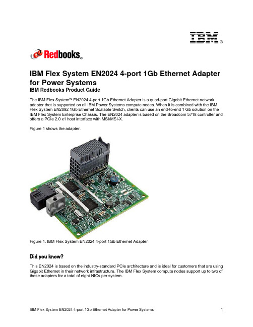
®IBM Flex System EN2024 4-port 1Gb Ethernet Adapter for Power SystemsIBM Redbooks Product GuideThe IBM Flex System™ EN2024 4-port 1Gb Ethernet Adapter is a quad-port Gigabit Ethernet network adapter that is supported on all IBM Power Systems compute nodes. When it is combined with the IBM Flex System EN2092 1Gb Ethernet Scalable Switch, clients can use an end-to-end 1 Gb solution on the IBM Flex System Enterprise Chassis. The EN2024 adapter is based on the Broadcom 5718 controller and offers a PCIe 2.0 x1 host interface with MSI/MSI-X.Figure 1 shows the adapter.Figure 1. IBM Flex System EN2024 4-port 1Gb Ethernet AdapterDid you know?This EN2024 is based on the industry-standard PCIe architecture and is ideal for customers that are using Gigabit Ethernet in their network infrastructure. The IBM Flex System compute nodes support up to two of these adapters for a total of eight NICs per system.Part number informationThe following table lists the ordering part number and feature code for the adapter.Table 1. Ordering part number and feature codeDescription Feature code(e-config)IBM Flex System EN2024 4-port 1Gb Ethernet Adapter1763The EN2024 4-port 1Gb Ethernet Adapter part number includes the following items: One adapter●Documentation CD●Important Notices flyer●FeaturesThe IBM Flex System EN2024 4-port 1Gb Ethernet Adapter has the following features: Dual Broadcom BCM5718 ASICs●Quad-port Gigabit 1000BASE-X interface●Two PCI Express 2.0 x1 host interfaces, one per ASIC●Full-duplex (FDX) capability, which enables simultaneous transmission and reception of data on the ●Ethernet networkMSI and MSI-X capabilities, up to 17 MSI-X vectors●A total of 17 receive queues and 16 transmit queues●A total of 17 MSI-X vectors that support per-queue interrupt to host●Function Level Reset (FLR)●ECC error detection and correction on internal SRAM●TCP, IP, and UDP checksum offload●Large Send offload, TCP segmentation offload●Receive-side scaling●Virtual LANs (VLANs): IEEE 802.1q VLAN tagging●Jumbo frames (9 KB)●IEEE 802.3x flow control●Statistic gathering (SNMP MIB II, Ethernet-like MIB [IEEE 802.3x, Clause 30])●Comprehensive diagnostic and configuration software suite●ACPI 1.1a-compliant: multiple power modes●Wake-on-LAN (WOL) support●Preboot Execution Environment (PXE) support●RoHS-compliant●Supported serversThe following table lists the IBM Flex System compute nodes that support the adapters.Table 2. Supported serversFor more information about the expansion cards that are supported by each blade server type, see this IBM® ServerProven website:/servers/eserver/serverproven/compat/us/I/O adapter cards are installed in the slot in supported servers (such as the x240) as shown in the following figure.Figure 2. Location of the I/O adapter slots in the IBM Flex System p270 Compute NodeSupported I/O modulesThese adapters can be installed in any I/O adapter slot of a supported IBM Flex System compute node. One or two compatible 1 Gb or 10 Gb I/O modules must be installed in the corresponding I/O bays in the chassis. The following table lists the switches that are supported. When connected to the 10 Gb switch or pass-thru module, the internal switch ports operate at 1 Gb speeds.To maximize the number of usable adapter ports, you might also need to order switch upgrades to enable morel ports as listed in the table. Alternatively, for CN4093, EN4093R, and SI4093 switches, you can use Flexible Port Mapping, which is a new feature of Networking OS 7.8 that allows you to minimize the number of upgrades needed. For more information, see the Product Guides for the switches that are available at this website:/portals/puresystems?Open&page=pg&cat=switchesThe table also specifies how many ports of the adapter are supported after the indicated upgrades are applied. Switches should be installed in pairs to maximize the number of ports enabled and to provide redundant network connections.Table 3. I/O modules and upgrades for use with the EN2024 4-port 1Gb Ethernet AdapterDescription Featurecode(e-config)Port count (per pairof switches)*1 Gb switchesIBM Flex System EN2092 1Gb Ethernet Scalable Switch + EN2092 1Gb Ethernet Scalable Switch (Upgrade 1) 35983594410 Gb switchesIBM Flex System Fabric CN4093 10Gb Converged Scalable Switch + CN4093 10Gb Converged Scalable Switch (Upgrade 1) ESW2ESU14IBM Flex System Fabric EN4093R 10Gb Scalable Switch + EN4093 10Gb Scalable Switch (Upgrade 1)ESW735964IBM Flex System Fabric EN4093 10Gb Scalable Switch + EN4093 10Gb Scalable Switch (Upgrade 1)359335964IBM Flex System EN4091 10Gb Ethernet Pass-thru37002IBM Flex System Fabric SI4093 System Interconnect Module + SI4093 System Interconnect Module (Upgrade 1)ESWAESW84IBM Flex System EN4023 10Gb Scalable Switch+ IBM Flex System EN4023 10Gb Scalable Switch (Upgrade 1) or Flex System EN4023 10Gb Scalable Switch (Upgrade 2)ESWDESWEESWF4Cisco Nexus B22 Fabric Extender for IBM IBM Flex System ESWB2* This column indicates the number of adapter ports that are active if indicated upgrades are installed. The adapter does not support the IBM Flex System EN6131 40Gb Ethernet Switch I/O module.The following table shows the connections between adapters that are installed in the compute nodes to the switch bays in the chassis.Table 4. Adapter to I/O bay correspondenceI/O adapter slot in the serverPort on the adapter Corresponding I/O module bay in the chassis Port 1Module bay 1Port 2Module bay 2Port 3*Module bay 1Slot 1Port 4*Module bay 2Port 1Module bay 3Port 2Module bay 4Port 3*Module bay 3Slot 2Port 4*Module bay 4Port 1Module bay 1Port 2Module bay 2Port 3*Module bay 1Slot 3(full-wide compute nodes only)Port 4*Module bay 2Port 1Module bay 3Port 2Module bay 4Port 3*Module bay 3Slot 4(full-wide compute nodes only)Port 4*Module bay 4* Ports 3 and 4 require Upgrade 1 of the EN2092 1Gb or EN4093 10Gb switch. The EN4091 Pass-thru only supports ports 1 and 2 (and only when two I/O modules are installed).The connections between the adapters that are installed in the compute nodes to the switch bays in the chassis are shown in the following figure. The figure shows half-wide servers, such as the p270 with two adapters.Figure 3. Logical layout of the interconnects between I/O adapters and I/O modulesOperating system supportThe IBM Flex System EN2024 4-port 1Gb Ethernet Adapter supports the following operating systems: AIX Version 6.1●AIX Version 7.1●IBM i 6.1●IBM Virtual I/O Server●Red Hat Enterprise Linux 6 for IBM POWER●SUSE LINUX Enterprise Server 11 for IBM POWER●Support for operating systems is based on the combination of the expansion card and the blade server on which it is installed. See the IBM ServerProven website for the latest information about the specific versions and service packs supported. Select the blade server, and then select the expansion card to see the supported operating systems: /systems/info/x86servers/serverproven/compat/us/WarrantyThere is a 1-year, customer-replaceable unit (CRU) limited warranty. When installed in a server, these adapters assume your system’s base warranty and any IBM ServicePac® upgrade.Physical specificationsThe adapter features the following dimensions and weight:Width: 100 mm (3.9 inches)●Depth: 80 mm (3.1 inches)●Weight: 13 g (0.3 lb)●The adapter features the following shipping dimensions and weight (approximate):Height: 58 mm (2.3 in)●Width: 229 mm (9.0 in)●Depth: 208 mm (8.2 in)●Weight: 0.4 kg (0.89 lb)●Regulatory complianceThe adapter conforms to the following standards:United States FCC 47 CFR Part 15, Subpart B, ANSI C63.4 (2003), Class A●United States UL 60950-1, Second Edition●IEC/EN 60950-1, Second Edition●FCC - Verified to comply with Part 15 of the FCC Rules, Class A●Canada ICES-003, issue 4, Class A●UL/IEC 60950-1●CSA C22.2 No. 60950-1-03●Japan VCCI, Class A●Australia/New Zealand AS/NZS CISPR 22:2006, Class A●IEC 60950-1(CB Certificate and CB Test Report)●Taiwan BSMI CNS13438, Class A●Korea KN22, Class A; KN24●Russia/GOST ME01, IEC-60950-1, GOST R 51318.22-99, GOST R 51318.24-99, GOST R●51317.3.2-2006, GOST R 51317.3.3-99IEC 60950-1 (CB Certificate and CB Test Report)●CE Mark (EN55022 Class A, EN60950-1, EN55024, EN61000-3-2, EN61000-3-3)●CISPR 22, Class A●Popular configurationsThe adapters can be used in various configurations. The following figure shows EN2024 4-port 1Gb Ethernet Adapters that are installed in both slots of the p270 (a model without the Embedded 10Gb Virtual Fabric Adapter), which in turn is installed in the chassis. The chassis also has four IBM Flex SystemEN2092 1Gb Ethernet Scalable Switches, each with Upgrade 1 installed to enable 28 internal ports. Figure 4. Example configurationThe following table lists the parts that are used in the configuration.Table 5. Components used when connecting the adapter to the 10 GbE switchesDescription Quantity Machine type /Feature Code7954-24X IBM Flex System p270 or other supported server 1 to 14 1763IBM Flex System EN2024 4-port 1Gb Ethernet Adapter 2 per server 7893-92X IBM Flex System Enterprise Chassis13598IBM Flex System EN2092 1Gb Ethernet Scalable Switch 43594IBM Flex System EN2092 1Gb Ethernet Scalable Switch (Upgrade 1)4 Related publicationsFor more information, see the following resources:Product Guides for all Flex System switches:●/portals/flexsystem?Open&page=pg&cat=switchesProduct Guides for Flex System compute nodes:●/portals/flexsystem?Open&page=pg&cat=nodesIBM Redbooks® publication IBM Flex System Products and Technology for Power Systems:●/abstracts/sg248256.htmlIBM Redbooks Product Guides for Flex System servers and options:●/portals/flexsystem?Open&page=pgbycatIBM Configurator for e-business (e-config):●/services/econfig/ServerProven for Flex System:●/systems/info/x86servers/serverproven/compat/us/flexsystems.htmlNoticesThis information was developed for products and services offered in the U.S.A.IBM may not offer the products, services, or features discussed in this document in other countries. Consult your local IBM representative for information on the products and services currently available in your area. Any reference to an IBM product, program, or service is not intended to state or imply that only that IBM product, program, or service may be used. Any functionally equivalent product, program, or service that does not infringe any IBM intellectual property right may be used instead. However, it is the user's responsibility to evaluate and verify the operation of any non-IBM product, program, or service. IBM may have patents or pending patent applications covering subject matter described in this document. The furnishing of this document does not give you any license to these patents. You can send license inquiries, in writing, to:IBM Director of Licensing, IBM Corporation, North Castle Drive, Armonk, NY 10504-1785 U.S.A.The following paragraph does not apply to the United Kingdom or any other country where such provisions are inconsistent with local law: INTERNATIONAL BUSINESS MACHINES CORPORATION PROVIDES THIS PUBLICATION "AS IS" WITHOUT WARRANTY OF ANY KIND, EITHER EXPRESS OR IMPLIED, INCLUDING, BUT NOT LIMITED TO, THE IMPLIED WARRANTIES OF NON-INFRINGEMENT, MERCHANTABILITY OR FITNESS FOR A PARTICULAR PURPOSE. Some states do not allow disclaimer of express or implied warranties in certain transactions, therefore, this statement may not apply to you. This information could include technical inaccuracies or typographical errors. Changes are periodically made to the information herein; these changes will be incorporated in new editions of the publication. IBM may make improvements and/or changes in the product(s) and/or the program(s) described in this publication at any time without notice.Any references in this information to non-IBM Web sites are provided for convenience only and do not in any manner serve as an endorsement of those Web sites. The materials at those Web sites are not part of the materials for this IBM product and use of those Web sites is at your own risk.IBM may use or distribute any of the information you supply in any way it believes appropriate without incurring any obligation to you. Information concerningnon-IBM products was obtained from the suppliers of those products, their published announcements or other publicly available sources. IBM has not tested those products and cannot confirm the accuracy of performance, compatibility or any other claims related to non-IBM products. Questions on the capabilities of non-IBM products should be addressed to the suppliers of those products. This information contains examples of data and reports used in daily business operations. To illustrate them as completely as possible, the examples include the names of individuals, companies, brands, and products. All of these names are fictitious and any similarity to the names and addresses used by an actual business enterprise is entirely coincidental.Any performance data contained herein was determined in a controlled environment. Therefore, the results obtained in other operating environments may vary significantly. Some measurements may have been made on development-level systems and there is no guarantee that these measurements will be the same on generally available systems. Furthermore, some measurement may have been estimated through extrapolation. Actual results may vary. Users of this document should verify the applicable data for their specific environment. COPYRIGHT LICENSE:This information contains sample application programs in source language, which illustrate programming techniques on various operating platforms. You may copy, modify, and distribute these sample programs in any form without payment to IBM, for the purposes of developing, using, marketing or distributing application programs conforming to the application programming interface for the operating platform for which the sample programs are written. These examples have not been thoroughly tested under all conditions. IBM, therefore, cannot guarantee or imply reliability, serviceability, or function of these programs.© Copyright International Business Machines Corporation 2014. All rights reserved.Note to U.S. Government Users Restricted Rights -- Use, duplication or disclosure restricted byGSA ADP Schedule Contract with IBM Corp.This document was created or updated on December 12, 2014.Send us your comments in one of the following ways:Use the online Contact us review form found at:●/redbooksSend your comments in an e-mail to:●***************.comMail your comments to:●IBM Corporation, International Technical Support OrganizationDept. HYTD Mail Station P0992455 South RoadPoughkeepsie, NY 12601-5400 U.S.A.This document is available online at /redbooks/abstracts/tips1243.html . TrademarksIBM, the IBM logo, and are trademarks or registered trademarks of International Business Machines Corporation in the United States, other countries, or both. These and other IBM trademarked terms are marked on their first occurrence in this information with the appropriate symbol (® or ™), indicating US registered or common law trademarks owned by IBM at the time this information was published. Such trademarks may also be registered or common law trademarks in other countries. A current list of IBM trademarks is available on the Web at/legal/copytrade.shtmlThe following terms are trademarks of the International Business Machines Corporation in the United States, other countries, or both:IBM®Power Systems™Redbooks®Redbooks (logo)®The following terms are trademarks of other companies:Intel, Intel logo, Intel Inside logo, and Intel Centrino logo are trademarks or registered trademarks of Intel Corporation or its subsidiaries in the United States and other countries.Java and all Java-based trademarks are trademarks of Sun Microsystems, Inc. in the United States, other countries, or both.Other company, product, or service names may be trademarks or service marks of others.IBM Flex System EN2024 4-port 1Gb Ethernet Adapter for Power Systems11。
TWN4 MULTITECH HF MINI READER* 13.56MHz Contactless Reader/Writer*Previously known as TWN4 Mini Reader MIFARE NFCElatec’s TWN4 MultiTech HF Mini Reader is designed for integration into machines, handheld computers or any other human interface devices such as displays, panels, etc. The focus has especially been set on size, flexibility and price. Thanks to its compact dimensions, integration directly on a PC board is possible.The TWN4 Simple Protocol enables quick software development cycles. All host communication is done via USB or asynchronous serial CMOS/TTL interface. The module offers positions for placement of two LEDs that can be controlled by software.An external Secure Access Module (SAM) is supported for enhanced security and cryptographic performance. This enables the application to perform secure transactions.Key Features:▪ 3.15 –5.5 V DC▪Powerful SDK for writing Apps which are executed directly on the reader▪Infield Upgradeable▪Direct chip-commands support▪Onboard 18kB flash storage▪Compact design (33x30x11mm)▪Integrated antenna▪USB, Serial (logical level 3.3V, CMOS 5V tolerant), SPI2), Clock/Data3), Wiegand3), 1-Wire2)▪Firmware based on versatile TWN4 technology▪ 4 GPIOs▪Supports connection of ISO7816 compatible SAM cards▪Industrial operating temperature: -25°C to +80°C▪Pin Compatible Upgrade from Mini Reader T3MR-F▪Step Model Data on requestElatec reserves the right to change any information or data in this document without prior notice. The distribution and the update of this document is not controlled. Elatec declines all responsibility for the use of product with any other specifications but the ones mentioned above. Any additional requirement for a specific customer application has to be validated by the customer himself at his own responsibility. Where application information is given, it is only advisory and does not form part of the specification. Disclaimer: All names are registered trademarks.Elatec GmbH Zeppelinstr. 182178 PuchheimGermanyPhone: +49 89 5529961 0Fax:+49 89 5529961 129********************© 2015 Elatec GmbH –DocRev7 –08/2015Technical DataFrequency13.56 MHzHousing NoneDimensions (L x W x H)32.6mm x 30.1mm x 11.2mm / 1.28inch x 1.19inch x 0.44inchPower Supply 3.15 –5.5 V DCCurrent Consumption RF field on: typically 110mATemperature Range Operating: -25°C up to +80°C (-13°F up to +176°F)Storage: -40°C up to +85°C (-40°F up to +185°F)Read-/Write Distance Up to 7cm / 2.75inch depending on tag and environmentHOST Interface USB, serial (logical level 3.3V,CMOS 5V tolerant), SPI2), Clock/Data3), Wiegand3), 1-Wire2))OS Support Windows XP, Vista, Embedded CE2), 7(32-/64-bit), 8, 8.1,10,Linux, Android,iOS2), MAC OS X2) Transmission Speed HOST: USB: Full speed (12Mbit) AIR: up to 848Kbit/sModes of Operation▪USB keyboard emulation –USB virtual COM port –Transparent (direct chip-commands support)▪CCID and PC/SC 2.011)Relative Humidity5% to 95% non-condensingAntenna IntegratedSupported Transponders Standard▪13.56MHz / ISO14443A: MIFARE Classic, Classic 1k & 4k EV17), Mini, DESFire EV1, Plus S&X, Pro X8), SmartMX8), Ultralight, Ultralight EV17), Ultralight C, SLE44R35, SLE66Rxx (my-d move), LEGIC Advant5), PayPass8), NTAG2XX7)▪13.56MHz / ISO14443B: Calypso8)incl. Innovatron radio protocol 14443-B'6), CEPAS8), HID iCLASS5), Moneo8), PicoPass8), SRI512, SRT512, SRI4K, SRIX4K▪13.56MHz / ISO15693: EM4x338), EM4x358), HID iCLASS5), ICODE SLI, LEGIC Advant5), M24LR16/64, Tag-it, SRF55Vxx (my-d vicinity)8), PicoPass8)▪13.56MHz / ISO18092 / NFC: NFCIP-1: Active and passive communication mode, Peer-to-Peer, NFC Forum Tag Type 1-4, Sony FeliCa9)Version I10)Standard + HID iCLASS, HID iCLASS SE/SR/SEOS (CSN and Facility Code/PAC)6)Certifications CE, WEEE, RoHS-II compliantMTBF500,000 hoursWeight Approx. 4gTWN4 MultiTech HF Mini Reader Option USB Development Board TWN4 MultiTech HF Mini Reader Order CodeStandard Version I T4MR-FT4MR-F-IT4MR-F-UT4MR-F-UIT4MK-F, including T4MR-F1)In Preparation2)On Request Only3)External Interface Required5)UID Only6)UID Only, read/write On Request 7)r/w enhanced security features on request 8)r/w in direct chip command mode 9)UID + r/w public area 10) Version I requires external TWN4 SIO CardDrawing (Component Side)PinningPin spacing2.54mm Pin Name Description1RESET Hard reset (input, low active, logic level, internally pulled-up)2PWRDWN Turn off voltage regulator (input, low active, logic level, internally pulled-up) 3GND Ground(USB black wire)4VCC Power supply input(3.15 –5.5V, USB red wire)5RXD/USB+UART RXD/USB Data+ (USB green wire)6TXD/USB-UART TXD/USB Data-(USB white wire)7Res.Reserved for future use (SCK from SPI host interface).8Res.Reserved for future use (SS-from SPI host interface).9VSAM 3.0V regulated supply for SAM10SAM_IO Bidirectional SAM I/O line11GPIO3General purpose input/output312GPIO2General purpose input/output213GPIO1General purpose input/output114GPIO0General purpose input/output015SAM_CLK SAM clock output16SAM_RST SAM reset output。
HPMLDL系列服务器hpML系列服务器HP ProLiant ML110G7(C8R00A)参数规格差不多参数产品类型工作组级产品类别塔式产品结构4U处理器CPU类型奔腾双核CPU型号奔腾双核G860CPU频率3GHzHP ProLiant ML330 G6(600911-AA1)参数规格差不多参数产品类型企业级产品类别塔式产品结构5U处理器CPU类型Intel 至强5600CPU型号Xeon E5620CPU频率 2.4GHz智能加速主2.666GHz频标配CPU1颗数量最大CPU2颗数量制程工艺32nm三级缓存12MB总线规格QPI 5.86GT/sCPU核心四核HP ProLiant ML330 G6(B9D22A)参数规格差不多参数产品类型企业级产品类别塔式产品结构5U处理器CPU类型Intel 至强5600 CPU型号Xeon E5606CPU频率 2.13GHz标配CPU1颗数量最大CPU2颗数量制程工艺32nm三级缓存8MB总线规格QPI 4.8GT/sHP ProLiant ML330 G6(600911-AA1)参数规格差不多参数产品类型企业级产品类别塔式产品结构5U处理器CPU类型Intel 至强5600CPU型号Xeon E5620CPU频率 2.4GHz智能加速主2.666GHz频标配CPU1颗数量最大CPU2颗数量制程工艺32nm三级缓存12MB总线规格QPI 5.86GT/sCPU核心四核HP ProLiant ML350 G6(638180-AA1)参数规格差不多参数产品类别塔式产品结构5U处理器CPU类型Intel 至强5600CPU型号Xeon E5606CPU频率 2.13GHz标配CPU1颗数量最大CPU2颗数量制程工艺32nm三级缓存8MB总线规格QPI 4.8GT/sCPU核心四核CPU线程四线程数主板HP ProLiant ML350 G6(600431-AA5)参数规格差不多参数产品类别塔式产品结构5U处理器CPU类型Intel 至强5600CPU型号Xeon E5620CPU频率 2.4GHz智能加速主2.666GHz频标配CPU1颗数量最大CPU2颗数量制程工艺32nm三级缓存12MB总线规格QPI 5.86GT/sCPU核心四核CPU线程八线程数HP ProLiant ML350 G6(594869-AA1)参数规格差不多参数产品类别塔式产品结构5U处理器CPU类型Intel 至强5600CPU型号Xeon E5620CPU频率 2.4GHz智能加速主2.666GHz频标配CPU1颗数量最大CPU2颗数量制程工艺32nm三级缓存12MB总线规格QPI 5.86GT/sCPU核心四核CPU线程八线程数HP ProLiant ML310e Gen8(686146-AA5)参数规格差不多参数产品类型企业级产品类别塔式产品结构4U处理器CPU类型Intel 至强E3-1200 v2 CPU型号Xeon E3-1220 v2CPU频率 3.1GHz标配CPU1颗数量最大CPU4颗数量制程工艺22nm三级缓存8MB总线规格DMI 5GT/sHP ProLiant ML310e Gen8(686147-AA5)参数规格差不多参数产品类型企业级产品类别塔式产品结构4U处理器CPU类型Intel 至强E3-1200 v2 CPU型号Xeon E3-1240 v2CPU频率 3.4GHz智能加速主3.8GHz频标配CPU1颗数量最大CPU4颗数量制程工艺22nm三级缓存8MBHP ProLiant ML350e Gen8(C3Q10A)参数规格差不多参数产品类型企业级产品类别塔式产品结构5U处理器CPU类型Intel 至强E5-2400 CPU型号Xeon E5-2403CPU频率 1.8GHz标配CPU1颗数量最大CPU4颗数量制程工艺32nm三级缓存10MB总线规格QPI 6.4GT/sHP ProLiant ML350e Gen8(C3Q08A)参数规格差不多参数产品类型企业级产品类别塔式产品结构5U处理器CPU类型Intel 至强E5-2400 CPU型号Xeon E5-2407CPU频率 2.2GHz标配CPU1颗数量最大CPU4颗数量制程工艺32nm三级缓存10MB总线规格QPI 6.4GT/sHP ProLiant ML350e Gen8(C3Q09A)参数规格差不多参数产品类型企业级产品类别塔式产品结构5U处理器CPU类型Intel 至强E5-2400 CPU型号Xeon E5-2420CPU频率 1.9GHz标配CPU1颗数量最大CPU4颗数量制程工艺32nm三级缓存15MB总线规格QPI 6.4GT/sHP ProLiant ML350e Gen8(C3F91A)参数规格差不多参数产品类型企业级产品类别塔式产品结构5U处理器CPU类型Intel 至强E5-2400 CPU型号Xeon E5-2430CPU频率 2.2GHz标配CPU1颗数量最大CPU4颗数量制程工艺32nm三级缓存15MB总线规格QPI 6.4GT/sHP ProLiant ML350p Gen8(646675-AA1)参数规格差不多参数产品类别塔式产品结构5U处理器CPU类型Intel 至强E5-2600 CPU型号Xeon E5-2609CPU频率 2.4GHz标配CPU1颗数量最大CPU2颗数量制程工艺32nm三级缓存10MB总线规格QPI 6.4GT/sHP ProLiant ML350p Gen8(668271-AA5)参数规格差不多参数产品类别塔式产品结构5U处理器CPU类型Intel 至强E5-2600 CPU型号Xeon E5-2620CPU频率2GHz智能加速主2.5GHz频标配CPU1颗数量最大CPU2颗数量制程工艺32nm。
第三方信息由 用户指南智能以太网适配器QL45212文档修订历史修订版 A,2015年1月11日修订版 B,2016年4月19日修订版 C,2017年1月27日修订版 D,2017年8月24日修订版 E,2018年1月31日更改受影响的章节第xv页上的“EMI 和 EMC 要求”经更新的EMI/EMC要求:⏹CE标记EMC指令符合性⏹利用EN55032来替换EN55022。
⏹VCCI⏹AS/NZS⏹新增的CNS 13438:2006 A类新增的VCCI语句第xvii页上的“VCCI:A类”第xvii页上的“产品安全符合性”经更新的产品安全符合性:⏹2014年的经更新的UL和UL CSA符合性⏹删除2006/95/EC低电压指令:⏹经更新的TUV EN60950-1和TUV IEC 60950-1第27页上的“VMware 驱动程序和驱动程序包”经更新的表3-5:⏹新增用于显示ESXi驱动程序版本的一列。
⏹新增用于解释针对ESXi6.5而被打包在一起的NIC和RoCE驱动程序的脚注。
向步骤4新增用于指出NPAR在最大速度为1G的第39页上的“使用入门”端口上不可用的注释。
新增用于解释由LLDP数据包使用的源MAC地址第47页上的“配置数据中心桥接”与出厂分配的适配器以太网MAC地址之间的区别的注释。
第53页上的“支持的操作系统和 OFED”更新了表6-1,为 OFED 4.8-1 GA 新增一列。
移除RHEL 7.2、SLES 11 SP4 和 SLES 12 SP2。
新增RHEL 7.4、SLES 12 SP3、CentOS 7.3 和CentOS 7.4更新了步骤2,新增Dynamic(动态)选项。
第55页上的“准备适配器”移除了“RoCE 应用程序和使用”小节并提升了第第69页上的“在 ESX 的适配器上配置 RoCE”72页上的“配置半虚拟 RDMA 设备 (PVRDMA)”第82页上的“在Windows上配置SR-IOV”更新了步骤13,为您的操作系统获取最新的适配器驱动程序,而不是使用内建驱动程序。
HP NC364T PCI Express Quad Port Gigabit Server AdapterUser GuidePart Number 445893-00BJune 2007 (First Edition)© Copyright 2007 Hewlett-Packard Development Company, L.P.The information contained herein is subject to change without notice. The only warranties for HP products and services are set forth in the express warranty statements accompanying such products and services. Nothing herein should be construed as constituting an additional warranty. HP shall not be liable for technical or editorial errors or omissions contained herein.Audience assumptionsThis document is for the person who installs, administers, and troubleshoots servers and storage systems. HP assumes you are qualified in the servicing of computer equipment and trained in recognizing hazards in products with hazardous energy levels.ContentsTechnician notes (4)Where to go for additional help (5)HP contact information (5)Introduction (6)Overview (6)UTP CAT5 cable (6)LED indicators (6)Installing an adapter (8)Installation overview (8)Preventing electrostatic discharge (8)Installing a low profile bracket (9)Installing an adapter in a server (9)Connecting the network cable (10)Specifications (11)HP NC364T PCI Express Quad Port Gigabit Server Adapter specifications (11)UTP cable specifications (12)Regulatory compliance notices (13)Regulatory compliance identification numbers (13)Federal Communications Commission notice (13)Class B equipment (13)Declaration of conformity for products marked with the FCC logo, United States only (14)Modifications (14)Canadian notice (14)European Union regulatory notice (15)Japanese class B notice (15)Korean class B notice (15)BSMI notice (16)Disposal of waste equipment by users in private households in the European Union (16)Electrostatic discharge (17)Preventing electrostatic discharge (17)Grounding methods to prevent electrostatic discharge (17)Acronyms and abbreviations (18)Index (20)Technician notesIn this sectionWhere to go for additional help (5)WARNING: Only authorized technicians trained by HP should attempt to repair this equipment. All troubleshooting and repair procedures are detailed to allow only subassembly/module-level repair. Because of the complexity of the individual boards and subassemblies, no one should attempt to make repairs at the component level or to make modifications to any printed wiring board. Improper repairs can create a safety hazard.WARNING: To reduce the risk of electric shock, personal injury, and damage to the equipment:•Do not attempt to service any parts of the equipment other than those specified in the following procedure. Any other activities may require that you shut down the server and remove the power cord.•Installation and maintenance of this product must be performed by individuals who are knowledgeable about the procedures, precautions and hazards associated with theproduct.WARNING: To reduce the risk of electric shock or damage to the equipment:•Do not disable the power cord grounding plug. The grounding plug is an important safety feature.•Plug the power cord into a grounded (earthed) electrical outlet that is easily accessible at all times.•Unplug the power cord from the power supply to disconnect power to the equipment.•Do not route the power cord where it can be walked on or pinched by items placed against it. Pay particular attention to the plug, electrical outlet, and the point where the cordextends from the server.CAUTION: To properly ventilate the system, you must provide at least 7.6 cm (3.0 in) of clearance at the front and back of the server.CAUTION: The server is designed to be electrically grounded (earthed). To ensure proper operation, plug the AC power cord into a properly grounded AC outlet only.NOTE: Any indications of component replacement or printed wiring board modifications may void any warranty.Where to go for additional help1.Go to the HP website ().2.Click Software & Driver Downloads from the left menu bar.3.Type the product name in the For product box and press Enter. For example, type NC370T.4.Download the drivers, firmware, or documentation as needed.HP contact informationFor the name of the nearest HP authorized reseller:•In the United States, see the HP US service locator webpage (/service_locator).•In other locations, see the Contact HP worldwide (in English) webpage(/country/us/en/wwcontact.html).For HP technical support:•In the United States, for contact options see the Contact HP United States webpage(/country/us/en/contact_us.html). To contact HP by phone:o Call 1-800-HP-INVENT (1-800-474-6836). This service is available 24 hours a day, 7 days a week. For continuous quality improvement, calls may be recorded or monitored.o If you have purchased a Care Pack (service upgrade), call 1-800-633-3600. For more information about Care Packs, refer to the HP website ().•In other locations, see the Contact HP worldwide (in English) webpage(/country/us/en/wwcontact.html).IntroductionIn this section Overview (6)UTP CAT5 cable (6)LED indicators (6)OverviewThe HP NC364T PCI Express Quad Port Gigabit Server Adapter is a high-performance, low-profile,Quad-Port PCI Express Ethernet adapter that delivers up to 1000 Mb/s Ethernet over twisted-pair (copper) category 5 or better cabling. It is powered by an Intel 82571EB chipset. The NC364T adapter, whichships with a standard-height chassis bracket and also includes a low-profile chassis bracket, has a fullyintegrated controller capable of auto-negotiating a link at 10, 100, or 1000 Mb/s. Network connectionis made through the four RJ-45 connectors. LED indicators show the link speed and activity. See LEDindicators (on page 6) for details. The adapter is a supported option for selected HP ProLiant servers. The adapter must be installed in a PCI Express slot.For the latest functionality, features, and operating system support for this adapter, see the HP website(/products/servers/networking/index-nic.html).UTP CAT5 cableThe NC364T adapter can use existing UTP CAT5 (or better) cable to deliver Gigabit Ethernet overcopper, according to the IEEE 802.3ab specifications. For new installations, CAT5e (enhanced CAT5)cable is recommended.For troubleshooting and other information about cabling, see UTP Cable Specifications (on page 12). LED indicatorsThe NC364T adapter has four auto-negotiating 10/100/1000 RJ-45 ports. LED indicators show activity, link and port speed. Standard-height and low-profile brackets are shown below with RJ-45 ports and LED indicators.The NC360T Gigabit Server Adapter LED indicators operate as described in the following table. LED indicator Status DescriptionACT/LINK On This mono-color green LED indicates that the link to the adapter is established. The adapter isreceiving power and the cable connection is working.Off No link to the adapter is established. Theadapter is not receiving power or the cable connection is faulty.Flashing The adapter is sending or receiving networkdata at 10/100/1000 Mb/s, as indicated by the 10/100/1000 (speed) LED. The adapter isreceiving power, and the cable connection is working.Speed Off The adapter is connected at 10 Mb/s.Green The adapter is connected at 100 Mb/s.Orange The adapter is connected at 1000 Mb/s.Installing an adapterIn this sectionInstallation overview (8)Preventing electrostatic discharge (8)Installing a low profile bracket (9)Installing an adapter in a server (9)Connecting the network cable (10)Installation overviewThis section describes installation precautions, how to install the adapter, and how to connect the network cable.WARNING: To reduce the risk of personal injury or damage to the equipment, consult thesafety information and user documentation provided with the server before attempting theinstallation.Many servers are capable of providing energy levels that are considered hazardous and areintended to be serviced only by qualified personnel who have been trained to deal with thesehazards. Do not remove enclosures or attempt to bypass any interlocks that may be providedfor the purpose of removing these hazardous conditions.WARNING: Installation of this adapter should be performed by individuals who are bothqualified in the servicing of computer equipment, and trained in the hazards associated withproducts capable of producing hazardous energy levels.This adapter is intended to be installed in Certified (UL or CSA) ITE equipment havinginstructions for adding and removing user installed components such as PCI, PCI-X, and PCIExpress devices. Refer to the equipment instructions to verify that it is suitable for user installedcomponents and that it has the power capacity to support all of the installed components.NOTE: Before removing the cover of your server, refer to the HP documentation for the propermethods for installing a PCI Express card and avoiding electric shock hazards. Preventing electrostatic dischargeTo prevent damaging the system, be aware of the precautions you need to follow when setting up thesystem or handling parts. A discharge of static electricity from a finger or other conductor may damagesystem boards or other static-sensitive devices. This type of damage may reduce the life expectancy of the device.To prevent electrostatic damage:•Avoid hand contact by transporting and storing products in static-safe containers.•Keep electrostatic-sensitive parts in their containers until they arrive at static-free workstations.•Place parts on a grounded surface before removing them from their containers. • Avoid touching pins, leads, or circuitry.•Always be properly grounded when touching a static-sensitive component or assembly. Installing a low profile bracketYou may have to install a low profile bracket to complete the product installation. The low profile bracket replaces the existing standard profile bracket shipped on the product.To install a low profile bracket:1.Using a correctly sized slotted screwdriver, carefully remove the two board lock screws located at the top and bottom of the connector. 2. Remove the standard profile bracket and place the low profile bracket over the connector. Be carefulnot to damage the connector or bind the low profile bracket to the connector.Installing an adapter in a serverThe NC364T can be installed in a standard or low-profile PCI Express slot. The kit includes brackets for both slot types. See the HP ProLiant server documentation for additional information on how to safely install a PCI Express card in the server.1.Power down the server, unplug the power cord from the power outlet, and then remove the server access panel. 2. Remove the expansion slot cover from a PCI Express slot.WARNING: To reduce the risk of personal injury from hot surfaces, allow the drives and the internal system components to cool before touching them.3.Firmly seat the adapter in a PCI Express slot and secure the adapter bracket. 4. Replace the access panel and plug in the power cord.Connecting the network cableTo secure the cable, plug the cable connector into the RJ-45 port. Ensure that the tab on the plug clicks into position indicating that it is properly seated.For more information, see UTP cable specifications (on page 12).SpecificationsIn this sectionHP NC364T PCI Express Quad Port Gigabit Server Adapter specifications (11)UTP cable specifications (12)HP NC364T PCI Express Quad Port Gigabit Server Adapter specificationsSpecification ValueNetwork Controller Chipsets Two intel® 82571GB Dual MAC/PHYBus Type x4 PCI Express v1.0aBus Width Four laneOn-board Memory 96 KBData Transfer Method Bus Master DMABoot ROM Support YesManagement Capabilities WOL, PXE 2.2, ACPI 1.1aPower Requirement 1250 mA @ 12V maximumData Transmission Rate 10 Full/10 Half, 100 Full/100 Half, 1000 FullStandards Supported IEEE 802.3, IEEE 802.3u, IEEE 802.3ab, IEEE 802.3x (flow control), IEEE802.3ad (link aggregation), IEEE 802.1p (QoS), IEEE 802.1q (VLAN tagging),IEEE802.3zDimensions 12.95 cm x 6.86 cm [5.1 in x 2.7 in (L x W)] (without bracket)Connector and Distances 10BASE-T: Category 3, 4, or 5 UTP 100 M (328 ft)100BASE-TX: CAT5 UTP 100 M (328 ft)1000BASE-TX: CAT5 UTP 100 M (328 ft)Interrupts Supported Automatically configuredTemperature Range Operating: 0°C to 55°C (32°F to 131°F)Storage: -65°C to 85°C (-85°F to 185°F)Relative Humidity (non-condensing) Operating: 10% to 90% Storage: 5% to 95%Safety Compliance UL Mark (US and Canada)CE MarkEN 60590RoHS (European Union)UTP cable specificationsThe NC364T adapter can use existing UTP CAT5 (or better) cable to deliver Gigabit Ethernet overcopper, according to the IEEE 802.3ab specifications. For new installations, CAT5e (enhanced CAT5) cable is recommended.Maximum distances for Gigabit over copper cable are 100 meters (328 feet).To connect to the network, the NC364T uses the following cable for 1000Base-T transmission:•CAT5 UTP or better twisted-pair•22-26 AWG, 100Ω @ 1 MHz•EIA/TIA 568a or EIA/TIA 568bRegulatory compliance noticesIn this sectionRegulatory compliance identification numbers (13)Federal Communications Commission notice (13)Class B equipment (13)Declaration of conformity for products marked with the FCC logo, United States only (14)Modifications (14)Canadian notice (14)European Union regulatory notice (15)Japanese class B notice (15)Korean class B notice (15)BSMI notice (16)Disposal of waste equipment by users in private households in the European Union (16)Regulatory compliance identification numbersFor the purpose of regulatory compliance certifications and identification, this product has been assigneda unique regulatory model number. The regulatory model number can be found on the product nameplatelabel, along with all required approval markings and information. When requesting complianceinformation for this product, always refer to this regulatory model number. The regulatory model number is not the marketing name or model number of the product.Federal Communications Commission noticePart 15 of the Federal Communications Commission (FCC) Rules and Regulations has established RadioFrequency (RF) emission limits to provide an interference-free radio frequency spectrum. Many electronicdevices, including computers, generate RF energy incidental to their intended function and are, therefore, covered by these rules. These rules place computers and related peripheral devices into two classes, Aand B, depending upon their intended installation. Class A devices are those that may reasonably beexpected to be installed in a business or commercial environment. Class B devices are those that mayreasonably be expected to be installed in a residential environment (for example, personal computers).The FCC requires devices in both classes to bear a label indicating the interference potential of the device as well as additional operating instructions for the user.Class B equipmentThis equipment has been tested and found to comply with the limits for a Class B digital device, pursuantto Part 15 of the FCC Rules. These limits are designed to provide reasonable protection against harmfulinterference in a residential installation. This equipment generates, uses, and can radiate radio frequency energy and, if not installed and used in accordance with the instructions, may cause harmful interference to radio communications. However, there is no guarantee that interference will not occur in a particularinstallation. If this equipment does cause harmful interference to radio or television reception, which canbe determined by turning the equipment off and on, the user is encouraged to try to correct theinterference by one or more of the following measures:•Reorient or relocate the receiving antenna.•Increase the separation between the equipment and receiver.•Connect the equipment into an outlet on a circuit that is different from that to which the receiver is connected.•Consult the dealer or an experienced radio or television technician for help. Declaration of conformity for products marked with the FCC logo, United States onlyThis device complies with Part 15 of the FCC Rules. Operation is subject to the following two conditions:(1) this device may not cause harmful interference, and (2) this device must accept any interferencereceived, including interference that may cause undesired operation.For questions regarding this product, contact us by mail or telephone:•Hewlett-Packard CompanyP. O. Box 692000, Mail Stop 530113Houston, Texas 77269-2000•1-800-HP-INVENT (1-800-474-6836). (For continuous quality improvement, calls may be recorded or monitored.)For questions regarding this FCC declaration, contact us by mail or telephone:•Hewlett-Packard CompanyP. O. Box 692000, Mail Stop 510101Houston, Texas 77269-2000•1281-514-3333To identify this product, refer to the part, series, or model number found on the product. ModificationsThe FCC requires the user to be notified that any changes or modifications made to this device that arenot expressly approved by Hewlett-Packard Company may void the user’s authority to operate theequipment.Canadian noticeThis Class B digital apparatus meets all requirements of the Canadian Interference-Causing EquipmentRegulations.Cet appareil numérique de la classe B respecte toutes les exigences du Règlement sur le matérielbrouilleur du Canada.European Union regulatory noticeThis product complies with the following EU Directives:•Low Voltage Directive 2006/95/EC•EMC Directive 2004/108/ECCompliance with these directives implies conformity to applicable harmonized European standards(European Norms) which are listed on the EU Declaration of Conformity issued by Hewlett-Packard for this product or product family.This compliance is indicated by the following conformity marking placed on the product:This marking is valid for non-Telecom products and EU harmonized Telecom products (e.g. Bluetooth).This marking is valid for EU non-harmonized Telecom products.*Notified body number (used only if applicable—refer to the product label)Hewlett-Packard GmbH, HQ-TRE, Herrenberger Strasse 140, 71034 Boeblingen, Germany Japanese class B noticeKorean class B noticeBSMI noticeDisposal of waste equipment by users in private households in the European UnionThis symbol on the product or on its packaging indicates that this product must not be disposed of withyour other household waste. Instead, it is your responsibility to dispose of your waste equipment by handing it over to a designated collection point for the recycling of waste electrical and electronicequipment. The separate collection and recycling of your waste equipment at the time of disposal will help to conserve natural resources and ensure that it is recycled in a manner that protects human health and the environment. For more information about where you can drop off your waste equipment for recycling, please contact your local city office, your household waste disposal service or the shop where you purchased the product.Electrostatic dischargeIn this sectionPreventing electrostatic discharge (17)Grounding methods to prevent electrostatic discharge (17)Preventing electrostatic dischargeTo prevent damaging the system, be aware of the precautions you need to follow when setting up thesystem or handling parts. A discharge of static electricity from a finger or other conductor may damagesystem boards or other static-sensitive devices. This type of damage may reduce the life expectancy of the device.To prevent electrostatic damage:•Avoid hand contact by transporting and storing products in static-safe containers.•Keep electrostatic-sensitive parts in their containers until they arrive at static-free workstations.•Place parts on a grounded surface before removing them from their containers.•Avoid touching pins, leads, or circuitry.•Always be properly grounded when touching a static-sensitive component or assembly. Grounding methods to prevent electrostatic dischargeSeveral methods are used for grounding. Use one or more of the following methods when handling orinstalling electrostatic-sensitive parts:•Use a wrist strap connected by a ground cord to a grounded workstation or computer chassis. Wrist straps are flexible straps with a minimum of 1 megohm ±10 percent resistance in the ground cords.To provide proper ground, wear the strap snug against the skin.•Use heel straps, toe straps, or boot straps at standing workstations. Wear the straps on both feet when standing on conductive floors or dissipating floor mats.•Use conductive field service tools.•Use a portable field service kit with a folding static-dissipating work mat.If you do not have any of the suggested equipment for proper grounding, have an authorized resellerinstall the part.For more information on static electricity or assistance with product installation, contact an authorizedreseller.Acronyms and abbreviationsACPIAdvanced Configuration and Power InterfaceAPMadvanced power managementCSACanadian Standards AssociationDMAdirect memory accessIEEEInstitute of Electrical and Electronics EngineersLEDlight-emitting diodeMDImedium dependent interfaceMDI-Xmedium dependent interface-crossoverNICnetwork interface controllerPCI ExpressPeripheral Component Interconnect ExpressPXEPreboot Execution EnvironmentRoHSRestriction of Hazardous SubstancesUTPunshielded twisted pairVDCvoltage direct-currentWOLWake-on LANIndexCcable configuration 11cable connectors 11 cables, networking 9Eelectrostatic discharge 7, 16Ffeatures 5Ggrounding methods 16Iinstallation overview 7 installing adapters 8NNIC LEDs 5Rregulatory compliance notices 12 Sspecifications 10UUTP CAT5 cable 11。