空冷器使用维护说明书
- 格式:pdf
- 大小:283.69 KB
- 文档页数:16
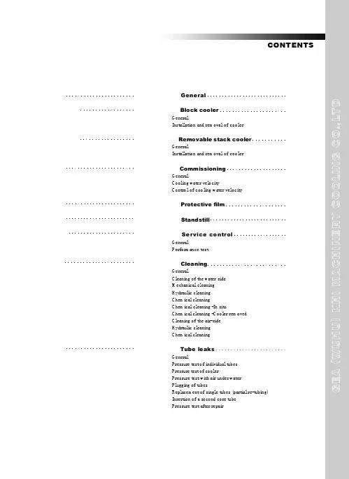
Air-water Coolers Installation Operation Maintenance ManualCONTENTS1 General2 Installation and removal of cooler3 Commissioning4 Protective film5 Standstill6 Service control6.1 General6.2 Performance test7 Cleaning7.1 General7.2 Cleaning of the water side7.2.1 Mechanical cleaning7.2.2 Hydraulic cleaning7.2.3 Chemical cleaning7.2.3.1 Chemical cleaning -Insitu7.2.3.2 Chemical cleaning-Cooler removed7.3 Cleaning of the air-side7.3.1 General7.3.2 Hydraulic cleaning7.3.3 Chemical cleaning1. GeneralThe water cooler is a finned tube heat exchanger .The hot air flows through the fins on the outside of the tubes and the cooling fluid flows through the tubes. The heat exchanger surface of the cooler consists of elliptical core tubes with rectangular threaded on fins or round core tubes with either wound-on fins or continuous flat plate fins. The bond between fin and tube is achieved either by mechanical means or by soldering.The core tubes are rolled into the tube sheets at each end of the tubes with roller.Side wall form an integral part of the cooler and are bolted to tube sheets.Water Headers (Namely connection and Return headers) are provided for water handling. The number of separation baffles conforms to the number of water passes. The headers are bolted to the tube sheets, gaskets interposed to form a seal. Plugs in the header are provided for cooler venting and draining.The materials for headers, tube, sheets and core tubes are chosen in accordance with the specification of the cooling water to be used and the recommended water velocity in the tubes.2.Installation and removal of the coolerRead all the maintenance instructions before you begin bundling this product.The cooler should be installed where it is accessible for cleaning, but not where the general public has access to it. Only let trained personnel with profound knowledge of the product and the appropriate safety rules carry out any work on the cooler.Prior to installation of the cooler ,the transport covers of the air side and the blanks on the water connection flanges are to be removed .The air and water side sealing surfaces ,which areprotected priot to shipping, must be cleaned by the use of turpentine.The cooler can either be mounted to the engine as a self mounted in the air duct as a cantilever unit. The air side connections are bolted to the air ducts using gaskets or sealing compound provided by the engine builder.The cooling water pipes are bolted to connection flanges on the connection header using gaskets also provided by the engine builder.To avoid deformation and stresses when installing the cooler all connecting surfaces must be parallel and the tolerances should be kept as small as possible.All connections are to be air and water tight. Transport lugs are provided on the side walls forlifting and handling of the complete cooler. Lifting lugs are also welded to the tube stack side walls. Prior to installation of the cooler casing into the air duct the tube stack can be removed by means of unscrewing the bolts holding the protruding tube sheet to the casing frame and removal of the gland packing or cover plate at the extension end tube sheet. At the fixed end of tube stack threads are provided in the water header for eyebolts to be used when lifting and pulling out.3. CommissioningThe cooler is subject to a hydraulic pressure test in our factory. It is however recommended to carry out a test with the specified test pressure before installation.If after prolonged storage or extended standstill the geared gaskets are leaking, tightening of the geared bolts might prevent further leakage. If this is not sufficient the header gaskets must be replaced. A pressure test with specified test pressure should be carried out after replacement.When refitting the headers ,tighten the bolts in the order .Tightening torque :70NmAfter assembly of the cooler is completed the cooler is circulated with the specified cooling water quantity prior to venting.For cooler venting, the vent plugs in the headers are removed. After the air has escaped from the cooler the plugs are fitted again. Venting should be repeated shortly after cooler is taken into operation. Venting of the complete cooling system is better than venting only thecooler and should therefore be preferred.With multi-circuit or multi-stage coolers, each circuit or stage should be vented separately.After a leak test has been carried out on all plant components, and the water flow has been checked to en-sure there are no restrictions, the cooler can be put into operation.Upon accelerating the engine to the nominal load the air temperature should be measured before and after the cooler and the cooling water flows set in accordance with the nominal water flows stated in the performance data sheet for the cooler in question.Never operate at min. velocity for a prolonged period of time. The nominal water flow stated in the performance data sheet for the cooler in question should be maintained.Frequent fluctuation of the water velocity impede the formation of a protective film on the tube inside, which are vital for corrosion protection. A too low water velocity encourages dirt deposits and a too high velocity causes erosion. To throttle the water flow or improper position of the water intake could lead to oxygen enriched water which favors corrosion. To keep the water flow, and so the watervelocity, constant also during part load operation ,control devices should be installed.4. Protection filmMeasures to assure the formation of a strong and durable protective film.The inherent good chemical corrosion-resistance of cop-per and copper alloys is due to their ability to form a natural protective film which is difficult to dissolve.New cooler tubes lacking a sufficiently strong protective film should never be operated with contaminated water, as deposits on the material surface would prevent the formation of such a protective film.For the above reason clean fresh water is used for the hydraulic test of the heat exchanger. The utilization of contaminated water should also be avoided during test runs. During test runs it is recommended to add small quantity of easily soluble ferrous sulphate (FeSO4.7H2O) to the cooling water to make sure that a good protective film is formed before operating with contaminated water.It is sufficient to add about 5mg/l to cooling water during a period of one hour every 24 hours. Adding of ferrous sulphate should, if possible, be repeated during normal operation until the first inspection is carried out.An appropriate valve for adding ferrous sulphate should be provided in the piping close to the water inlet nozzle of the cooler.5. StandstillA standstill of the cooling water system, leaving the cooler undrained, is hazardous for cooler parts made of copper , copper alloys, steel and cast iron.For copper and copper alloys standstills are especially hazardous prior to the formation of a protective film or in the case that the destruction of the same must be feared for reason of deposit attacked by putrefaction products such as ammonium compounds and hydrogen sulphide.If possible, cooler operation should not be interrupted during the first 2 months after commissioning if the cooler can not be drained.However, if there is a failure in cooling water supply and operation is resumed within 3 days and then for a prolonged period of time kept uninterrupted, the cooler may be left undrained.It must be then guaranteed that the tubes are free from deposits. If deposits have formed, the cooler should be drained, the tubes cleaned and flushed with clean water prior to being dried. We recommend the use of warm or pre-dried air for blowing through the tubes.The coolers need to be vented adequately. If sea water, brackish or saline water(chloride content>500mg/l) is used as cooling water, water with low salinity (drinking water quality)should be used for flushing. In case of standstill within the start-up period of 2 months which is expected to last for more than 3 days, and where deposits must be feared, the cooler should be drained, flushed and dried.To avoid standstill corrosion after the first 2 months of operation the above described cleaning procedure should be repeated by every standstill lasting longer than 2 weeks.In case of permanent service interruptions after the start-up period it may be necessary to limit the standstill where the cooler is kept undrained to 3 days and operate the unit under conditions as recommended for the start-up period.During short standstill the cooler can be operated at low cooling water velocity soformation of deposits in the tubes can be prevented. Operating with low water velocities is to be preferred to cooling water standstill in the tubes as putrefaction products, such as ammonium compounds and hydrogen sulphide are washed away from their point of origin.During winter time standstill if frost injury to the cooler could occur the cooler should be drained also during the shortest standstill.6.Service control6.1 GeneralFor service control, thermometers are to be installed in the air ducts and in the cooling water piping before and after the cooler, we recommend to keep record of the air and water temperatures in the machine log book periodically. Further control instruments can be provided in accordance with the individual requirement.In case of the occurrence of a major amount of condensate after the cooler, further condensation can be prevented ,or at least limited, by the use of a bypass control of the cooling water as previous described.A possibility to drain the condensate must be assured.6.2 Performance testThe performance guarantee given is main expressed by the temperature difference between cold water and cold air during normal operation and should be checkedfrom time to time.In the event that a considerable increase of the guaranteed temperature difference observed during normal operation ,this might be due to accumulation of air in the cooler. To remedy the above the cooler should be vented by using the procedure previously described.In case a performance increase cannot be achieved by proceeding as above and provided no other disturbance can be found , the cooler needs cleaning.A differential pressure gauge can also be used to check whether or not cleaning of the air or water side of the cooler is necessary. We recommend to install differential pressure gauges in the air duct and water piping before and after the cooler.7. Cleaning7.1 GeneralCleaning of the water and air side heat exchange surfaces is imperative for a long and trouble free operation of the cooler. The cleaning intervals vary with the mode of operation, cooling water quality, intake air characteristics etc.Cleaning can be done by either mechanical , hydraulical or chemical means.7.2 Cleaning of the water sideRegular cleaning is necessary. The cleaning intervals depend on the cooling water used. Cleaning of the water side is not only required to maintain the thermal performance of the cooler. Scaling increases the risk of biting corrosion and obstacles partly blocking the tubes favors erosion.7.2.1 Mechanical cleaningMechanical cleaning is done by use of nylon brushes fitted to a rod. The length of the rod corresponds to the tube length of the cooler in question and the type of brush is chosen in accordance with the finned tube type. The brush with rod is part of each cooler delivery.Mechanical cleaning can be done insitu or with the cooler removed. At least one header needs to be removed when cleaning. For header removal threaded holes with the same dimension as the header bolts are provided in the header flange to serve as jacking screws. The wet tubes should be thoroughly brushed clean one after the other and the dirt flushed out until no residues are left. After the cleaning is completed the headers are refitted using new gaskets. Venting must be repeated after cooling water is refilled7.2.2 Hydraulic cleaningHydraulic cleaning is carried out with the cooler removed using a high pressure spray gun with special nozzle to remove dirt deposits inside the tubes.7.2.3 Chemical cleaningChemical cleaning can be carried out in-situ or with the cooler removed.7.2.3.1 Chemical cleaning In-situTo ensure that the cooler is always operated without fouling or scaling in the tubes we recommend an integrated and continuously operating chemical cleaning system to be fitted.Such cleaning system comprises of a circuiting pump and a detergent tank with the necessary piping and shut off valves. The detergent circuit is connected to the cooling water inlet and outlet piping between their shut off valves and the water header flanges.Prior to cleaning, the cooling water flow is interrupted to allow the cooler to drain via the cooling water outlet piping. For draining the vent screw are removed. After draining, the cooling water valves are closed. The valves of the cleaning circuit are opened and the circulating pump switched on. The vent screws are fitted after venting completed.It is recommended to connect the cleaning circuit to the cooling water outlet piping in such a way that the deter-gent flow is opposite to the normal cooling water flow.When cleaning completed the cooler is drained leaving no detergent in the cooler. The valves of the cleaning circuit are closed and the cooling water valves opened. Flushing is done with normal cooling water. Reventing of the cooler is necessary.Scaling deposits in the cooling tubes can be removed by chemical cleaning as well. For removal, a 10% HCL hydrochloric, or muriatic acid is used and a 0.5% inhibitor (specifically suitable for the individual tube material added.After cleaning, the cooler is to be flushed thoroughly, i.e. no detergent residues are allowed to be left in the cooler.This is most important in case the cooler is shut down for a short time after cleaning.If the cooler is chemically cleaned in mounted position the headers need not be dismounted. For chemical cleaning we recommend to use suitable detergents to clean:The instructions and handling guidelines provided by the manufacturer of the detergent in question should always be observed when using the chemical.7.2.3.2 Chemical cleaning Cooler removedChemical cleaning while the cooler is removed is required if neither mechanical or hydraulic cleaning proved successful and if the cooler is not connected to a continuously operating cleaning system.The complete cooler with attached header will be connected by the use of blind flanges to an external cleaning circuit or filled with detergent on the water side. Time of saturation depends on the grade of deposit. If the result is not satisfying, cleaning should be repeated.7.3 Cleaning of the air-side7.3.1 GeneralCleaning of the air-side should be done early enough to avoid accumulations of soot and oil on the fins, which after a period of time form a hard crust that is difficult to remove, as well as the deposition of other crack products as for instance residues that form a sulphuric acid (compound with condensate) when left on the fins and tubes for some time.7.3.2 Hydraulic cleaningHydraulic cleaning is effected when the cooler is removed .A high pressure spray gun as described above is suitable also for this requirement. We recommend a nozzle size of 3mm. If the water jet attacks the cooling tubes vertically, i.e. in parallel to the fins, a pressure of 120bar is suitable to be applied at a distance of 2m from the fin surface.7.3.3 Chemical cleaningWe recommend chemical cleaning of the air side while the cooler is removed.The water headers are detached from the cooler bundle .The tube bundle is then immersed into a chemical cleaning bath. The time of immersion is a function of the degree of fouling. When cleaning completed, the cooler is to be flushed by applying a powerful water jet. If the result isstill not satisfying, cleaning should be repeated.To intensify the cleaning effect of the bath and shorten the cleaning time, it is recommended to circulate the detergent. The chemical detergents can also be applied by spraying. The following detergents are recommended for air side cleaning.The instructions and handling guidelines provided by the manufacturer of the detergent in question should always be observed when using the chemical.。
空气调节器维修手册一、前言空气调节器(Air Conditioner)是一种常见的家用电器,用于调节室内空气温度和湿度,提供舒适的环境。
然而,由于长期使用或其他原因,空调可能会出现一些故障,需要及时维修。
本手册旨在为用户提供维修空调的详细指导,帮助您解决常见的问题。
二、安全须知在进行空调维修之前,请务必注意以下安全事项:1. 首先,确保断开电源并拔下电源插头。
2. 在进行任何维修工作之前,戴上绝缘手套和护目镜,确保个人安全。
3. 不要在未经许可的情况下打开空调主机或触摸内部零件,以免引发电击或其他危险。
三、故障排除1. 无法启动- 检查电源是否插好。
确认插头连接完好。
- 检查电源线是否断裂或损坏。
如有破损,请及时更换。
- 检查电源开关是否处于关闭状态。
尝试打开电源开关。
- 如仍无法启动,可能是供电问题,请联系专业维修人员进行检查修复。
2. 空调运行不正常- 检查空调显示屏是否正常。
若有故障码显示,请按照说明书的故障码表进行排查。
- 检查空调滤网是否堵塞。
定期清洗或更换滤网。
- 检查空调外部散热器是否受到阻碍。
确保周围无物体遮挡,保持良好的散热。
- 如问题仍未解决,请联系售后服务中心或专业维修人员。
3. 制冷效果差- 检查空调是否正常供电。
确保电压和电流符合要求。
- 检查空调温度设置是否合适。
调整温度设置为所需的舒适温度。
- 检查空调滤网是否清洁。
如果滤网堵塞,清洗或更换它。
- 检查空调室内和室外机组的换热器是否清洁。
如果有污垢,清洗它们。
- 如问题仍未解决,请联系专业维修人员进行检查修理。
4. 异常噪音- 检查空调固定螺丝是否松动。
如有松动,请紧固它们。
- 检查空调安装是否牢固。
如果有松动,请进行安装调整和固定。
- 检查空调室内和室外机组是否平稳。
如果不平稳,可以调整基座或垫片,以稳固机组。
- 如问题仍未解决,请联系专业维修人员进行检查修理。
四、维护保养定期维护保养空调可以延长其使用寿命和维持良好的性能。
空冷器操作维护检修规程一、空冷器的操作(一)、空冷器管束操作时应注意的事项:1、管内介质、温度、压力均应符合设计条件,严禁超压,超温操作;2、管内升压、升温时,应缓慢逐级递升,以免因冲击驟热而损坏设备;3、空冷器正常操作时,应先开启风机,再向管束内通入介质.停止操作时,应先停止向管束内通入介质,后停风机;4、易凝介质于冬季操作时,其程序与3条相反;5、负压操作的空冷器开机时,应先开启抽气器,管内达到规定的真空度时再启动风机,然后通入管内介质,停机时,按相反程序操作.冬季操作时,开启抽气器达到规定真空度后,先通入管内介质,再启动风机,以免管内冻结无法运行;6、停车时,应用低压蒸汽吹扫并排净凝液,以免冻结和腐蚀;7、开车前应将浮动管箱两端的紧定螺钉卸掉,保证浮动管箱在运行过程中可自由移动,以补偿翅片管热胀冷缩的变形量。
(二)、空气冷却器风机操作应注意的事项:1、风机叶片角度应按照设计提供的数据安装盲目增大叶片安装角,会使电机超负荷运行2、运行过程中应密切注意电机电流情况,尤其是用风量较大时。
二、空冷器的维护保养(一)、空冷器空冷风机系统的维护保养及使用注意事项1、日常巡检●运行中有无异常性声音和振动.●回转部件有无过热、松动.2、定期维护保养●每三个月通过注油嘴加注锂基润滑油.●定期调整三角带的松紧度,并检查三角带胶带的磨损程度,磨损严重的应及时予以更换.●全面检查各零、部件的紧固状态一年一次.●风筒与叶轮的径向间隙检查一年一次.●叶片角度及叶片沿风机轴向跳动应每年检查、调整一次.●清除风机叶片表面油污,检查叶片损坏,半年一次.3、检修注意事项●风机使用角度不得超过规定的调角范围以防电机过载.●加注黄油不应超过油腔的2/3,以免轴承过热.●每次检修和更换电机时,必须注意接线相应,应保证风机叶轮俯视顺时针方向旋转.●皮带传动机构的皮带应保持一定的张紧力。
如过于松弛,则电机的动力无法有效的传递至风机,风机效率下降,甚至造成皮带飞出的事故。
P 型系列空气冷却器使用说明书泰州市裕华制冷设备制造有限公司空气冷却器一、概况P型系列空气冷却器(又称冷风机)是一种使用于各种冷库的冷却降温设备,P型系列空气冷却器有PC、PCE和PE型三种型式分别使用于不同库温的冷库。
它具有结构紧凑、重量轻、不占有冷库实用面积等优点,与自然对流排管相比,它能使冷库内贮藏的食品迅速降温,大大提高了贮藏食品的保鲜度。
二、产品用途P型系列空气冷却器可与不同制冷量的压缩冷凝机组配套,用于不同库温的冷库中作为制冷设备。
其中PC型适用于库温为0℃左右的冷库,如保存鲜蛋或蔬菜的库。
PCE型适用于库温为-18℃左右的冷库,作为肉类、鱼类等冷冻食品的冷藏用。
PE型适用于库温为-25℃或低于-25℃的冷库作为鲜肉或鲜鱼制品及调理食品等冻结用。
三、产品特点1、壳体采用喷塑钢板、轧花铝板或不锈钢板,耐腐蚀,外形美观,可满足不同可户的需求。
2、盘管以错排方式布置,传热效率高,通过机械胀管将铝翅片套在铜管上连接牢靠。
3、该产品为厂内配线,所有接线均置于一个接线盒内,安装维修方便。
4、选用的电机和风叶,噪声低,运转平稳并可根据用户需要选用防爆型电机。
5、排水管中央最低处设有排水接口,排水可靠。
6、槽型吊架,安装方便。
7、U型管状不锈钢管及氧化镁填料的电加热管,置于盘管中,融霜效果良好,几种可选的融霜方式(电加热管、水、热气)。
8、出厂前全部经过保压充氮处理。
四、型号说明空气冷却器的传热面积(m2)空气冷却器的名义制冷量KW(kcal/h)融霜方式:对电融霜省略此相,W表示水冲霜适用制冷剂(对R22省略此项)冷却物冷藏库用C表示冻结物冷藏库用CE表示速冻库用E表示吊顶式用P表示五、冷风机安装前的检查1、在拆开外包装后应检查各连接部件有无松动,如有松动应重新紧固。
2、检查轴流风机的风叶安装在电机轴上是否牢固,风叶与防护罩是否碰伤。
3、如因运输而造成冷风机有损坏或变形时,应修复后才能吊装。
1大卡/小时=1.163W适用于库温:-2 ~ +5℃的冷库备注:根据用户需要可进行特殊加工1大卡/小时=1.163W适用于库温:+2 ~ -20℃的冷库备注:1、可根据用户要求加工成水冲霜; 2、根据用户需要可特殊加工。
运行维护手册版 本 号: 1 编制 审核: 修改纪录 日期: 日期:空冷凝汽器运行维护手册文件号:C00009036运行维护手册C00009036空冷岛运行维护手册-1.docpage 2 of 11目录 页次 1 概述 31.1 缩写代码 31.2 参考系统图(P&I )图 31.3 主要部件 3见各项目供货范围 3 2 运行32.1 抽真空系统 32.1.1 水环真空泵(或射汽抽气器)单元 3 2.2 空冷凝汽器 (ACC)32.2.1 概述 32.2.2 运行 32.2.3 ACC 的启动、ACC 的停机、ACC 风机控制的配置等 3详见“Cxxxx9025控制描述”。
32.2.4 特殊运行工况 33.维护管理33.1风机的维护管理 33.1.1开机的准备及步骤 33.1.2试运转 33.1.3风机维护 33.2减速机的维护管理 33.2.1减速机的启动 33.2.2维护 3运行维护手册1 概述1.1 缩写代码ACC 直接空冷凝汽器(Air cooled condenser)Condenser bundles 顺流凝汽管束(Co-current flow heat exchanger bundles)Dephlegmator bundles逆流凝汽管束(Counter-current flow heat exchanger bundles)PCMS 电厂控制和监测系统(Plant’s control and monitoring system)Control SystemGC 功能组控制(Group control)SGC 子组控制Sub-group control1.2 参考系统图(P&I)图相关的参考系统图(P&I 图)见:ACC系统(P&I )图Cxxxx66001.3 主要部件见各项目供货范围2 运行2.1 抽真空系统在启动阶段各台水环真空泵(或射汽抽气器)的启停是根据需要自动控制的。
Air Cooled CondenserOperation and MaintenanceManual空冷凝汽器运行维护手册Ref.-No.: D3461_MAN7901Purchaser 采购方: ShanDong Electric Power Engineering山东电力设计院End User最终用户: Shenhua Yili Power Plant 神化亿利电厂SPX - Contract - No. 合同号: 260-03461SPX Cooling Technologies GmbHErnst-Dietrich Platz 240882 RatingenPhone电话 : +49 - 2102 - 1669-786Fax传真 : +49 - 2102 - 1669-215Project Manager项目经理 : Mrs. Hui Sun-DegenhardPhone电话 : +49 - 2102 - 1669-239Final Issue终版 :Revision版本 : 0Date日期 :Register登记 : d0025956_Index目录1.GENERAL SAFETY CONCEPT一般安全概念错误!未定义书签。
1.1G ENERAL I NSTRUCTIONS总说明错误!未定义书签。
1.2S AFETY I NSTRUCTIONS FOR O PERATION,I NSPECTION AND R EPAIR错误!未定义书签。
运行,检查,修理安全指导错误!未定义书签。
1.3S TART-UP S AFETY安全启动错误!未定义书签。
1.4S AFETY DURING P ERMANENT O PERATION持续运行时的安全措施错误!未定义书签。
1.5S HUT-DOWN S AFETY P ROCEDURE停机安全步骤错误!未定义书签。
1.6D ANGER WHEN S AFETY I NSTRUCTIONS ARE NOT FOLLOWED不遵守安全指导的危险错误!未定义书签。
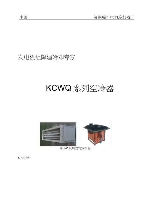
发电机组降温冷却专家KCWQ系列空冷器KCW系列空气冷却器1.应用范围:用于火电机组、水轮发电机组运行环境的空气降温、火电氢冷机组的氢气降温;2.设备结构及技术规格选型:2.1设备结构经我公司多年来对电站使用的各种空冷器过程中,进行使用情况综合分析,对空冷器的设计、制造工艺实施了一系列的改进完善,形成我公司KCW系列空冷器,经改进完善后的空冷器,其结构及各项指标更加满足用户的使用要求;(空冷器设计压力:0.6〜I.OMpa;工作压力:0.2〜0.5Mpa)KCW系列空冷器,结构以“可卸盖板式”为主,因两侧水室便于拆装,在使用维护过程中便于对水室内部和散热管基管内部进行清洗维护;KCW(系列空冷器主要由左右水室、左右管板、复合式翅片管、上下侧板等主要部件构成,空冷器的水室与管板用螺栓连接(中间使用专用胶垫密封)见下图:1 2 3 4 5 6 7 8 9 101左水室2冷却水进水法兰3冷却水出水法兰4左管板5换热管6下侧板7上侧板8右管板9右水室10 螺栓图2-1 KCWQ “可卸盖板式”空冷器结构2.2技术规格选型KCWQ空气冷却器规格尺寸3.设备特点:3.1 “可卸盖板式”空冷器的左右水室内表面,采用国内先进的“汽车底盘装甲”工艺,进行特殊防腐处理,防止其生锈影响冷却水质,经此工艺加工后的水室内表面,能长期缓解水气腐蚀、冷却水体流动及水体内所含杂质对水室内表面的冲刷撞击,彻底解决了因水室内表面涂漆层脱落、水室内表面生锈等不利因素影响冷却水质的问题;图3-1经“汽车底盘装甲”工艺处理后的水室内表面图3-2基管与管板胀接后照片3.2左右管板采用优质钢板加工,部件外表面采用先进镀锌工艺进行镀锌处理,避免其腐蚀生锈影响冷却水质,并在一定程度上延长了设备使用寿命;翅片管基管与左右管板基管孔处,采用国内最先进的胀接工艺进行胀接密封,确保冷却水在翅片管基管内部正常循环流动,冷却水不会因渗漏随被降温的热空气进入到机组内部,确保机组安全运行(见图3-2);3.3两块侧板与左右管板连接形成空冷器主体,侧板主梁采用国标等边角钢设计制造,(可根据电站实际安装需要,在侧板主梁上钻出一定数量的把合孔,便于空冷器主体与定子及相关设备部件连接并密圭寸);3.4 KCW(系列空冷器使用的核心换热元件是复合式翅片管,复合式翅片管的基管与铝翅片的接触热阻低,在较大温度变化范围内能保持稳定的低值,传热系数高,基管由外层铝管壁保护不受腐蚀,对温度突变及振动有良好抗力;单位长度换热面积大,传热量高,结构可靠,寿命长;翅片表面光滑无毛刺无皱折、不易结垢不易变形、易于清洗(可用高压水冲洗),易于排除表面积水、流动阻力低,能长期保持良好的传热性能。
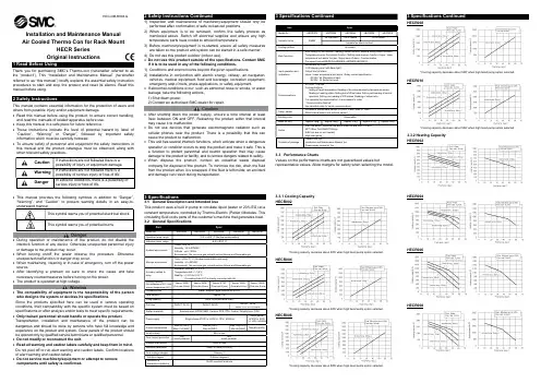
Installation and Maintenance Manual Air Cooled Thermo Con for Rack MountHECR Series Original InstructionsThank you for purchasing SMC’s Thermo-con (hereinafter referred toas the “product”). This “Installationand Maintenance Manual” (hereinafter referred to as “this manual”) briefly explains the essential safety instruction procedures to startandstoptheproductandresetits alarms. Readthismanual before using.This manual contains essential information for the protection of users and others from possible injury and/or equipment damage.Read this manual before using the product, to ensure correct handling,and read the manuals of related apparatus before use. Keep this manual in a safe place for future reference.These instructions indicate the level of potential hazard by label of “Caution”, “Warning” or “Danger”, followed by important safety information which must be carefully followed.To ensure safety of personnel and equipment the safety instructions in this manual and the product catalogue must be observed, along with other relevant safety practices.This manual provides the following symbols in addition to “Danger”, “Warning”, and “Caution” to present warning details in an easy-to-understand manner.During operation or maintenance of the product, do not disable the interlock function of any device. Otherwise unexpected personnel injury or damage to the product may occur.When turning on/off the power observe the procedure. Otherwise unexpected malfunction or danger may occur.When maintaining, cleaning or in case of emergency, turn off the power source.After identifying a problem be sure to check the cause and take necessary countermeasures before turning on the power. The product is operated at high voltage.The compatibility of equipment is the responsibility of the person who designs the system or decides its specifications.Since the products specified here can be used in various operating conditions, their compatibility with the specific system must be based on specifications or after analysis and/or tests to meet specific requirements. Only trained personnel should handle or operate the product.Transportation, installation and maintenance of the product can be dangerous and should be done by persons who have full knowledge and experience on the product and system. Cover panels of the product should be opened only by qualified service technicians or qualified personnel. Do not modify or reconstruct the unit.Read all warning and caution labels carefully and keep them in mind. Do not peel off or rub alert warning and caution labels. Confirm locations of alert warning and caution labels.Do not service machinery/equipment or attempt to remove components until safety is confirmed.After shutting down the power supply, ensure a time interval at least *Cooling capacity decrease about 20W when high head pump option selected.HECR004*Cooling capacity decrease about 50W when high head pump option selected.HECR006*Cooling capacity decrease about 50W when high head pump option selected.3 Specifications ContinuedHECR008*Cooling capacity decrease about 50W when high head pump option selected.HECR010*Cooling capacity decrease about 50W when high head pump option selected.3.3.2 Heating Capacity HECR002HECR004HECR006HECR008HEC-OM-R008-GHECR0103.3.3 Pump CapacityHECR002HECR004HECR006HECR008 / HECR010RTD wiring4 Special Features ContinuedFan speed control (HECR004,HECR006,HECR008,HECR010)Fan speed is controlled automatically in accordance with the heat load.5 Installation5.1 InstallationPay special attention to the safety of all personnel when installing andtransporting the product.Do not install the product unless the safety instructions have been readand understood.The product is heavy, be careful when installing or moving the product.Always transport the product using both handles.Leakage from the product may damage peripheral equipment. Install adrain pan under the product to capture leakage. Furthermore, mountdevices like a leak sensor on the installed drain pan to detect leakage sothat it can alert operators around the area.Install the product above 0.6m from the floor.5.2 EnvironmentDo not use in an environment where the product is directly exposed towater, oil, corrosive gases, chemicals, salt water or steam.The product should be installed upright on a stable base.Do not install the product in a location where the air inlet and air outletvents are blocked. Also do not use the product in a sealed enclosure.Do not use in an explosive atmosphere.Do not mount the product in a location where it can be exposed toprolonged sunlight. Use a protective cover.Do not mount the product in a location where it is subject to strongvibrations and/or shock. Check the product specifications.Do not use the product where it can be exposed to strong electrical ormagnetic emissions.Do not mount the product in a location where it is exposed to noisesources (such as discharging equipment, large relay and thyristor).Do not mount the product in a location with an altitude of more than1000 meters.Do not mount the product where it is exposed to materials such assilicone, which may generate harmful gas.Install the product in a location where the ambient temperature range isbetween 10 to 35°C and the relative humidity range is between 35 to80%. No dew condensation is allowed on the unit.Do not mount the product in a location exposed to radiant heat.5.3 MountingWhen mounting the product to a cabinet, use a design which shall holdthe weight at the bottom. Ensure safety with transportation test if theproduct is to be installed on a transportation device such as a trailer.Mount the product using the fixing holes in the front of the product. UseM5,M6 screws (bolts) or equivalent to the fix the product.Be sure to correctly tighten all screws to the required torque.(M5:3.0Nm, M6:5.2Nm)5.4 PipingEnsure that the power source and the power supply of the product isturned off (or the power plug must come off )Ensure the flow rate of the circulating fluid is as high as possible tomaintain the temperature stability. Therefore, the length of the externalpiping should be minimized and internal diameter should be as large aspossible. Piping must have sufficient strength for the maximumdischarge pressure of the circulating circuit.Likewise, if a tube is bent or multiple elbow fittings are used, the pipingresistance will increase and the flow rate will decrease. If the flow ratefalls, the temperature stability will decrease.If installing a tank externally, only a sealed tank should be used. Do notuse an open tank.Normal When high head pump option selectedNormal When high head pump option selectedNormal When high head pump option selectedNormal When high head pump option selectedEnsure that the INLET and OUTLET for circulating fluid is connected correctly. If any valves are used ensure that they do not restrict the flow, otherwise low flow may cause an alarm.When installing piping or fittings, ensure sealant material does not enter inside the port. When using seal tape, leave 1.5 to 2 threads exposed on the end of the pipe/fitting.Be sure to correctly tighten the fitting fittings to the required torque(Rc1/4:12 to 14 N ・m, Rc3/8:15 to 20N ・m). 5.5 WiringEnsure that the power source and the power supply of the product is turned off before connecting the various connectors and power supply cable.Supply disconnecting device according to IEC60974-1 and IEC60947-3 for the product must be provided in the end system.Do not install the disconnecting device in the place where the operation is difficult. And also the switch of the disconnecting device must comply with the direction of the switch specified by IEC60447. Preparation and wiring of power supply cable 1) Strip the sheath from both ends of the cable.2) Disassemble the power supply connector. Crimp one end of the cable to L, N, E inside of the connector, then reassemble the power supply connector.3) Connect the other end of the cable to a plug or terminals (e.g. crimped terminal).Ensure that there is enough space between the power supply cable and the communication cable of the product and power cables of other equipment.Ensure the power supply and ground connections are made correctly. Be sure to provide the grounding. The PE line of the power supply cable is available for grounding. Do not connect the ground in common with the ones for equipment that generates strong electromagnetic noise or high frequency.When an external temperature sensor is connected, connect the sensor with a shield cable. Use a platinum resistant temperature sensor (Pt100ohm, 3-wiring type, class A, 1mA).Connect the host to this unit with a twisted pair shield cable when applying communication function or external sensor and alarm output function.When using the Communication connector and Signal/External temperature sensor, connect the circuit separated from the mains circuit by reinforced insulation.Ensure that external instruments connecting to this product provide the enclosure complied with UL61010-1 and use the cable which provide flame resistance (over VW-1). 5.6 Filling the product1. Ensure that the power source and the power supply of the product is turned off (or the power plug must come off).2. Remove the reservoir cap.(When setting the product again, confirm the level of fluid does not exceed the “H ” mark)3. If using Ethylene Glycol, refer to the suppliers Material Safety Data Sheet (MSDS) and wear Personal Protective Equipment (PPE) as appropriate.4. Fill the circulating fluid into the reservoir. Stop filling once the level of fluid reaches the “H” mark.5. Turn on the power switch to fill the piping with the fluid.6. When the piping is filled with the circulating fluid, the level of the reservoir decreases and low fluid level alarm (ERR20) arises accordingly. Then, turn off the power supply once again.7. Repeat the step from 4 to 6 until ERR20 alarm doesn’t appear anymore. 8. Then, replace the cap on the reservoir and tighten it securely. 9. Keep the fluid level between H and L of the level indicator.Never touch the power switch with wet hands to avoid electrical shock.Do not touch the surface when the set temperature is high. Temperature of the tank and the chassis near the tank could be high.Fluid other than water or Ethylene Glycol (up to 20%) should not be used as circulating fluid. Using such fluid may lead to leakage or damage of the pump.Operation of the pump with a large amount of air left in the piping for prolonged period may damage the pump. Remove air from piping before starting operation.If the power switch is turned on without circulating fluid, the pump could be damaged.Take care not to spill water over the product when supplying water to the reservoir. When a spill is made, wipe it off immediately and only supply power after it has dried. If this procedure is neglected, it may cause damage to the product.If a fluid with low conductivity such as DI water is used as circulating fluid, it can cause static electricity due to friction and damage the product. Take measures to minimize the static electricity from circulating fluid. If the product is operating for a long time with large temperature fluctuations after reaching the set temperature, the product may be damaged. Please set the PID values by using the auto-tuning function.6 Operation6.1 Power UpWhen power is turned on, the software version is indicated on display panel for approx. 1 second. 6.2 OperationThe product begins operation immediately after the power is turned on. The pump and heat exchanger will be running and the product will begin temperature control.6.3 SettingsThree different levels of settings are available depending on the content, which needs to be set. Level 1: Used in normal operation e.g. settingof target temperature and offset.Level 2: Used at maintenance and initial settingfor setting of controller/PID.Level 3: Used at initial setting for thecommunication function.The key functions are as follows:[SEL]: Used to show the item that needs to bechanged in selected mode level. [▽△]: Used to change the value of the item selected. [RET]: Used to fix the value changed by [▽△] key.Press again to return to current temperature indication.[AT]: Used to start auto tuning in auto tuning mode(This function works when the control operation mode is 2 in level setting 1)When pressed during auto tuning, the auto tuning is stopped.When no input is made within 1 minute regardless of setting mode, the display returns to the current temperature indication.The data input is written to FRAM and memorized after the power supply is turned off.To return all of the setting values to default: Turn on the power supply while pressing [SEL] and [RET] keys.6.3.1 Level 1-Settings6.3.3 Level 3-SettingsHECR002HECR002-A5-E(option)HECR004HECR004-A5-E(option)Displays the measured temperature.#1 and #2 change when [ ] or [ ] is N E (Earth) LCrimped terminal L E N PlugCable quantity and size; 3 cores, 14AWG(include earth) 100℃, 300V, VW-1 or moreHECR006HECR006-A5-E(option) HECR008HECR008-A5-E(option) HECR010HECR010-A2-E(option)8 Key PartsHECR002 / HECR004 / HECR006HECR008 / HECR0109.1Daily Check1) Indicationofdisplaypanel: Checktemperature conditionandconfirmwhether or not an alarm has occurred.2)Confirm that the heat sink and panel are free from dust. A large amountof dust may impair the performance.3)Confirm there is no leakage of circulating fluid and check the conditionof the piping (e.g. no tight bends or crushed pipes).4) Confirm there is no abnormal sound, smell or heating from the product.When cleaning the panel or heat sink use a vacuum cleaner to removethe dust. Do not use water or steam since it leads to rusting of the frame.9.2 General MaintenanceReplace the circulating fluid regularly to avoid any problems due to algaeor contamination.<Drain circulating fluid>HECR002 / HECR004 / HECR0061. Drain circulating fluid from the Fluid IN.Loosen the reservoir cap to help draining. (Do not remove the cap)2. To drain from the piping, blow air (0.1MPa, about 1 minute) from FluidOUT to Fluid IN. Close the reservoir cap while blowing.HECR008 / HECR0101. Drain circulating fluid from the Drain port.Loosen the reservoir cap to help draining. (Do not remove the cap)2. To drain from the piping, blow air (0.1MPa, about 1 minute) from FluidOUT to Drain port. Close the reservoir cap and Fluid IN while blowing.The repair and maintenance services of this unit are performed only atSMC factory. SMC does not provide on-site repair or maintenanceservice in a national or overseas situation.It is recommended to prepare spare units to minimize downtime due tothose repair and maintenance services.Drain the fluid from the product when it is returned for the repair andmaintenance service. If the fluid is left inside, an accident and damagecan result during transportation.Do not make any modification to the product.Do not disassemble the product, unless required by installationinstructions.If fluid other than water is used, wash the circulating fluid circuit withwater or DI water before returning the product to SMC. Products thathave not been washed may not be accepted at the factory.10 Troubleshooting11 Declaration of ConformityBelow is a sample Declaration of Conformity(DoC) used for this product.An actual DoC will be supplied with each product.4-14-1, Sotokanda, Chiyoda-ku, Tokyo 101-0021 JAPANTel: + 81 3 5207 8249 Fax: +81 3 5298 5362URL https://Note: Specifications are subject to change without prior notice and any obligation on the part of the manufacturer.© 2022 SMC Corporation All Rights Reserved。
目录一、冰水机组操作说明 (1)1、冷水机组操作 (1)2、风机水泵操作 (1)3、冷水机组开停机顺序 (1)二、空调设备日常维护保养 (2)1、螺杆式冷水机组运行管理注意事项 (2)2、螺杆式冷水机组停机注意事项 (2)3、日常检查事项 (2)4、年度停机保养 (2)5、风机使用注意事项 (3)6、水泵日常维护 (4)7、膨胀水箱日常维护 (4)8、Y型过滤器日常维护 (4)9、过滤器日常维护保养 (4)10、风淋室日常维护保养 (5)三、洁净室注意事项 (5)四、附:.............................................................................................................................................1、风淋室使用说明书........................................................................................................ 1份1、冷却塔操作维护说明书................................................................................................ 1份1、水泵合格证及说明书.................................................................................................... 1份1、组合式空调机组合格证及说明书................................................................................ 2份一、冰水机组操作说明1、冷水机组的操作①开机前的准备工作1)确认机组和控制器的电源已接通。
发电机组降温冷却专家KCWQ系列空冷器KCWQ系列空气冷却器1.应用范围:用于火电机组、水轮发电机组运行环境的空气降温、火电氢冷机组的氢气降温;2.设备结构及技术规格选型:2.1设备结构经我公司多年来对电站使用的各种空冷器过程中,进行使用情况综合分析,对空冷器的设计、制造工艺实施了一系列的改进完善,形成我公司KCWQ系列空冷器,经改进完善后的空冷器,其结构及各项指标更加满足用户的使用要求;(空冷器设计压力:0.6~1.0Mpa;工作压力:0.2~0.5Mpa)KCWQ系列空冷器,结构以“可卸盖板式”为主,因两侧水室便于拆装,在使用维护过程中便于对水室内部和散热管基管内部进行清洗维护;KCWQ系列空冷器主要由左右水室、左右管板、复合式翅片管、上下侧板等主要部件构成,空冷器的水室与管板用螺栓连接(中间使用专用胶垫密封)见下图:1 2 3 4 5 6 7 8 9 101左水室 2冷却水进水法兰 3冷却水出水法兰 4左管板 5换热管 6下侧板7上侧板 8右管板 9右水室 10 螺栓图2-1 KCWQ “可卸盖板式”空冷器结构2.2技术规格选型KCWQ空气冷却器规格尺寸3.设备特点:3.1“可卸盖板式”空冷器的左右水室内表面,采用国内先进的“汽车底盘装甲”工艺,进行特殊防腐处理,防止其生锈影响冷却水质,经此工艺加工后的水室内表面,能长期缓解水气腐蚀、冷却水体流动及水体内所含杂质对水室内表面的冲刷撞击,彻底解决了因水室内表面涂漆层脱落、水室内表面生锈等不利因素影响冷却水质的问题;图3-1经“汽车底盘装甲”工艺处理后的水室内表面图3-2基管与管板胀接后照片3.2左右管板采用优质钢板加工,部件外表面采用先进镀锌工艺进行镀锌处理,避免其腐蚀生锈影响冷却水质,并在一定程度上延长了设备使用寿命;翅片管基管与左右管板基管孔处,采用国内最先进的胀接工艺进行胀接密封,确保冷却水在翅片管基管内部正常循环流动,冷却水不会因渗漏随被降温的热空气进入到机组内部,确保机组安全运行(见图3-2);3.3 两块侧板与左右管板连接形成空冷器主体,侧板主梁采用国标等边角钢设计制造,(可根据电站实际安装需要,在侧板主梁上钻出一定数量的把合孔,便于空冷器主体与定子及相关设备部件连接并密封);3.4 KCWQ系列空冷器使用的核心换热元件是复合式翅片管,复合式翅片管的基管与铝翅片的接触热阻低,在较大温度变化范围内能保持稳定的低值,传热系数高,基管由外层铝管壁保护不受腐蚀,对温度突变及振动有良好抗力;单位长度换热面积大,传热量高,结构可靠,寿命长;翅片表面光滑无毛刺无皱折、不易结垢不易变形、易于清洗(可用高压水冲洗),易于排除表面积水、流动阻力低,能长期保持良好的传热性能。
控制箱温度调节机系列宝鸡雷博精密工业有限责任公司目 录一、适用范围本机组主要用于对各种电气柜内的空气进行冷却、加热、除湿和净化处理,以保证电气元件在安全温度和湿度条件下可靠工作,延长其使用寿命。
适用于机械、电力、轻工、仪器仪表、纺织等行业对温湿度有较高要求的各类控制箱、配电柜及其它电气装置,也可用于小空间的温度、湿度调节。
二、安装(一) 安装要求1、机组应垂直安装在通风良好且远离灰尘处,另外应保证其外侧进出风口与墙壁或其它物体间距离在1m 以上。
2、机组周围不应存在腐蚀性气体和易燃易爆等危险气体,安装位置附近也不应有高温热源和其它发热物体,并避免阳光直接照射到机组上。
3、机组可安装在控制箱正面、侧面(LA-□□B/Q 型)或顶部(LA-□□C 型),加热器组件应安装在控制箱内,具体位置由用户自行确定。
安装部位结构件应能充分承受机组重量。
4、用户应按照产品样本规定,预先在控制箱上加工好机组的送回风口和安装孔。
送回风口的位置应确保箱内空气流向合理,循环畅通,温度均匀性好。
5、机组应使用专用电路供电,电源线截面积应符合相关规定,并在电路上安装规定容量的空气开关或保险装置及漏电断路器。
6、机组和控制箱应按有关电气安全标准要求,可靠接地。
7、机组在搬运或安装中,应避免受到撞击而损坏,同时不允许机组倒置或倾斜角度大于40°。
为此在运输和安装前,应尽量保持原包装,吊装时掌握好重心。
(二) 安装方法机组的安装参见图1、图2、图3所示,具体步骤如下:1.在机组安装面及内侧送回风口周围 粘贴泡沫塑料保温层;2.用M8×16螺栓+弹垫/平垫将机组固定在控制箱箱体上,注意安装方向要正确; 图1 天井式安装3.固定加热器组件,按电路图规定在XT1、XT2端子上接线;4.将排水软管固定在排水管口处(仅限于不带接水盒的机型,并避免其弯曲、上翘)。
弹平垫控制箱温度调节机控制箱×16螺栓后具有掉电保护功能。
空冷风机使用维护说明一、前言空冷风机是一种常见的散热设备,广泛应用于电子、通讯、工业等领域。
正确的使用和维护对于保证空冷风机的正常运行和延长使用寿命至关重要。
本文将详细介绍空冷风机的使用维护事项。
二、使用事项1.安装位置选择空冷风机应安装在通风良好的位置,避免被阻塞,以确保其正常运行。
同时,空冷风机应远离易燃物品及高温物品,防止发生事故。
2.供电电源稳定空冷风机必须使用稳定的供电电源,以免电压不稳定或电流过大对机器产生损坏。
建议使用专用的空调插座进行供电。
3.避免受潮空冷风机应远离潮湿的环境,避免受潮。
如在潮湿环境下使用空冷风机,应及时处理受潮部分,以免影响其正常运行。
4.使用温度控制在使用空冷风机时,应注意控制好工作环境的温度。
若温度过高,可能导致空冷风机过热,影响散热效果甚至引起设备故障。
5.定期清洁空冷风机的正常运行需要保持良好的散热效果,因此定期清洁非常重要。
可以使用吹气枪或软毛刷清理风扇叶片、散热片等部分的灰尘和杂物。
6.禁止过载使用在使用空冷风机时,应避免超载使用。
过载使用可能导致电机过热,严重时还会引发火灾等安全事故。
确保使用电流不超过空冷风机的额定电流。
三、维护事项1.定期检查电缆连接定期检查空冷风机电缆的连接情况,确保连接牢固且没有松动。
同时,注意检查电缆是否有磨损、破损或裸露的情况,及时更换磨损严重的电缆。
2.检查风扇运行情况定期检查风扇的运行情况,确保其转动灵活且不发出异常声音。
如发现异常应立即停机检查,并进行维修或更换。
3.清洁散热器定期清洁散热器,可使用吸尘器或软毛刷轻轻清除上面的灰尘。
不要使用湿布或带水的清洁剂,以防止水滴进入内部电路或电机。
4.检查电机温度定期检查空冷风机电机的温度。
正常情况下,电机温度应在工作厂家规定的范围内。
如超过规定温度,应立即停机并检查。
5.故障排除若出现空冷风机无法启动、噪音过大、发热不足、风力减小等故障,应及时停机检查。
可以先检查电源线连接是否松动,电源是否正常,如果没有问题,则需要进行更具体的故障排除。
空冷器维护保养规程1 适用范围本规程适用于公司燃驱离心式压缩机空冷器的维护保养。
2 维护保养规程2.1日维护保养2.1.1运行两个小时后,对轴承座(风机轴和电机)的温度进行测量,高于环境温度50℃以上检查轴承或更换轴承;2.1.2运行5到10个小时后,检查皮带的张紧力;2.1.3检查各连接件的紧固是否良好;2.1.4检查空冷器翅管是否存在跑、冒、滴、漏现象,观察翅管外部是否存在污垢,并及时清除。
2.2周维护保养检查半圆挡环是否卡进了叶片座的圆槽内,叶片定位顶丝是否符合要求。
2.3月维护保养2.3.1调整三角带的松紧度,并检查三角带胶带的磨损程度,磨损严重的应及时予以更换;2.3.2停运时每两月,采用手动方式转动一次风机轮毂和风机轴,从而使润滑油均匀地分布在所有的轴承部件上。
2.4季维护保养2.4.1通过注油嘴给轴承加注锂基润滑油,上轴承每次最多添加50g润滑油,下轴承每次最多添加60g润滑油;2.4.2检查并调节皮带张紧力。
2.5年维护保养2.5.1每半年对风机叶片表面进行清洗,检查叶片是否完好;2.5.2每半年对空冷器翅管外部进行全面清洗,清洗方法包括:空气喷嘴清洗、水流喷嘴清洗、喷射热水或蒸汽清洗、化学清洗等;2.5.3对空冷器翅管内部进行清洗,清洗方法包括:机械清洗、化学清洗、高压设备清洗等;2.5.4对各零、部件连接进行调整、紧固;2.5.5检查风筒与叶轮的径向间隙;2.5.6检查、调整叶片角度及叶片风机轴向跳动;2.5.7每运行50000小时(或者最多6年),清洗轴承和润滑油管(清除旧的润滑油)并充满新的润滑油;2.5.8在运行10000小时后,更换轴承。
4 安全注意事项4.1安全人员随时监测作业环境的可燃气体、氧气浓度,保证作业人员处于一个安全的作业环境;4.2重新加油时风机上轴承UCF215加油200g,风机下轴承443276加油300g,过量的润滑油将破坏轴承的密封垫圈;4.3当更换不同的等级/牌号的润滑油时,必须取下轴承,在装入新的润滑油前彻底的清除旧的润滑油并清洗干净;4.4操作维护保养过程中严格执行公司相关安全生产规定,不违规操作;4.5调整、维护、修理、清洗和保养必须在停机状态下进行;4.6做好维护保养记录。
空分冷冻机组操作及维护一、说明机组设计成单独使用,通过约克管理系统或其它自控系统与其它设备配合使用。
运行时,机组控制器监控冷冻水系统的温度,并发出恰当的指令,将温度维持在设定的范围内。
压缩机根据冷负荷调整运行,使机组制冷量与冷冻水系统的冷负荷相匹配。
从冷冻水中带走的热量最终由水冷式冷凝器排走。
二、启动确认机组和控制中心的电源已接通,所有的制冷剂检修阀均打开(逆时针旋转),并且冷冻水流量正常(除非采取了机组冷冻水泵停机控制,如果是这样的话,仅确认水泵电源接通即可)。
确认微处理器控制板上的系统开关(系统1或2)处于接通的位置。
按下键盘上的状态键,然后将键盘下面的机组ON/OFF拨动开关切换到接通(ON)的位置。
控制器将作一次预查,以确认日常/节假日时间表和任何一远程联锁装置均允许机组启动,所有的安全切断值都得到了满足,并且有冷负荷要求机组运行(即冷冻水温度超出了设定极限)。
如果预查时遇到问题,将会显示出来,没有问题而又有冷负荷的话,超前压缩机启动。
滞后压缩机的反重合启动定时器的状态将显示出来,后面跟着“无冷负荷”信息,直到控制系统要求它运行为止。
三、正常运行和停机一旦机组启动,所有的操作均为自动的。
经过初始的超前压缩机最小容量阶段后,控制系统将按冷冻水温度和温度变化的速率来调节机组的负荷。
如果冷负荷较高,控制器将增加超前压缩机的容量,并启动其它的压缩机;如果冷负荷较低,超前压缩机将持续在最低容量下运行,或者干脆停机,以免使冷冻水温度过低。
当出现后面这种情况时,待冷冻水温度再度上升后,超前压缩机将自动再启动。
一旦压缩机运行,随着制冷剂被压送到水冷式冷凝器中,排气压力将升高。
压缩机一运行,控制器将监控油压、电机电流和系统的其它各种参数,如排气压力、冷冻水温度等。
一旦出现任何问题,控制系统将立即采取相应的措施,并显示出故障的性质四、停机在任何时候,只要将键盘下面的机组ON/OFF拨动开关切换到断开的位置,就可以使机组停机。