AES数字音频接口标准简介
- 格式:pdf
- 大小:174.75 KB
- 文档页数:3
AES67标准“AES67是一个开放的网络数字音频标准,它是基于IP网络架构,采用现有的IT网络协议,实现低时延、高性能的专业音频传输的互用性指导方针。
它的开放协议与可兼容性,极大地推动了数字音频技术基于IP网络架构之上的发展。
AES67标准产生的背景从广播电视音频系统的发展进程来看:从使用诸多线缆的模拟音频系统,到引入了“同步”概念的数字音频系统,再到TDM音频矩阵系统,进而到基于以太网实现多个工作间网络互联音频系统,接下来到基于IP架构下实现远程互通互联(工作间之间、不同地域之间)的网络音频技术,如今已形成基于IP架构下的多地点集中式分布系统。
咅频技术能力的演进,IT技术的发展,让整个音视频技术行业搭上了IT 技术的顺风车,音频行业也面临AoIP( Audio over Inter- net Protocol,互联网协议架构下的音频)时代的到来。
目前媒体网络联盟MNA (Media Networking Alliance)通过的网络协议有四个,Livewire、Ravenna、QLAN、Dante。
这四个协议分别对应着业内用的最好的四个厂家,The Telos代表Livewire,Lawo 代表Ravenna,QSC代表QLAN,雅马哈代表Dante。
但是,不同网络协议间是互不兼容的,这对于用户来说非常麻烦。
因为用户大部分选择的不是某一个品牌,而是一个系统,这个系统里可能有很多不同设备,有的设备用这个协议,有的用那个,这些设备往往不能互通。
现在就是有这么一套互通的机制——AES67,能够把不同的协议联通在一起。
当前,Dante、Livewire、Ravenna、QLAN四个协议所覆盖的厂家已经达到90%以上,这意味着AES67标准能打通市场上90%的设备,并解决了用户最棘手的问题。
AES67标准的关键技术1、同步机制网络上任何地点的接收端通过一个公共时钟,可以与其他接收端同步回放,公共时钟可以保证所有流均被以相同的速率采样和还原,同一速率的多个流可以被轻易合成。

AES信号时钟失锁检测的初探及应用萨日娜;赵岩【摘要】本文对AES信号的数据结构、编码方式、自同步原理及时钟失锁监测原理进行了剖析,并对其在内蒙古广播电视台广播系统中的应用进行了阐述。
【期刊名称】《数字传媒研究》【年(卷),期】2015(032)003【总页数】4页(P29-32)【关键词】AES数据结构;编码方式;校验位;音频四选一【作者】萨日娜;赵岩【作者单位】内蒙古广播电视台,内蒙古呼和浩特市010058【正文语种】中文【中图分类】G220数字化广播时代,对于种类繁多的音源设备和各种传输链路来说数字音频信号的标准在播出系统中显得更为重要。
在常见的数字音频标准SPDIF、AES/EBU、MADI 中,AES/EBU更为主要和常用。
AES即AES/EBU标准,是由音频工程师协会/欧洲广播联盟(Audio Engineering Society/European Broadcast Union)制定的一种通过基于单根数字双绞线来传输数字音频数据的串行位传输协议。
其中AES是指AES3-2003标准,EBU是指EBU发布的数字音频接口标准EBU-3250,两者内容在实质上是相同的,统称为AES/EBU数字音频接口。
因此,AES/EBU标准常简称为AES、AES3标注,同时其对应的ANSI(美国国家标准学会 AMERICAN NATIONAL STANDARDS INSTITUTE)标准为ANSIS4.40-1992, IEC(国际电工委员会International Electro technical Commission,简称IEC)标准为IEC-958。
当采用非平衡传输时该标准遵循AES-3id-2001,此时称为AES3id。
2.1 平衡模式AES3-2003标准中建议使用数字音频双绞线作为标准AES信号的传输方式,该方式为平衡传输模式,详细电气特性见表1。
2.2 非平衡模式随着系统的复杂性和多样性的日益加剧,对AES信号的传输距离有了更高的要求。

数字音频协议介绍目录AES/EBU (1)ADAT (6)I2S (7)时分复用(TDM) (9)MIDI (11)AES/EBU简介:AES3: Audio Engineering Society Standard #3EBU: European Broadcasting UnionAES3 接口在1985 年已经被指定并在1992 年正式成为标准接口。
自从定为标准后,AES3 反复更新和调整以适应先进设备的要求,其应用非常普遍。
但另一方面来说这使得它有点复杂。
规格:•2 通道•平衡传输信号•XLR连接头•音频数据达24Bit / 192kHz•缆线长:100m 或更多•阻抗:110Ohm (±20%)•负载电平:输出端2 - 7 Vpp(110 Ohm ,缆线不能长)•大量的通道状态信息AES3 和AES/EBU 比较AES3 数字音频接口和AES/EBU 数字接口只在一个细节上有区别:EBU 标准规定在接口的发送端和接收端强制安装有耦合变压器,而这在AES3 标准中只是可选功能。
功能:发展AES3 标准的目的是为了使数字音频数据可以重复利用模拟音频信号传输网络,要构成一个传输网络需几万米的线来连接设备比如广播电台等。
这些都是平衡缆线,传输信号的频率可达10MHz,若进行适当的信号均衡的话缆线长度可达300m。
若需通过这些模拟信号音频线来传输数字信号的话,需满足以下几个条件,这些条件很容易就可以达到:•由于传输链可能有变压器,因此信号必须是不含直流分量。
•由于没有额外的缆线来传输位时钟(bit clock )和采样时钟(sample clock ),因此信号自身需携带有时钟信号。
•极性逆转对重拾音频信息无影响。
这些条件可以通过双向标记编码方案(bi-phase-mark coding scheme)来满足。
概述:通过双相标记编码,每个比特的边界都以切换信号极性的方法标记出来。
为了区分信号“1”与信号“0”,需在“1”位插入一个额外的过渡标记代码(如图所示)。
数字音频知识AES/EBU:实时立体声数字音频信号格式。
在相应设备之间进行传送。
这种格式是AudioEngineeringSociety/EuropeanBroadcastUnion(录音师协会/欧洲广播系统联盟)的缩写。
这种数字格式亦由这两个组织联合制定的。
AES/EBU是由平衡XLR口输出,其他方面同S/PDIF格式相似。
automatedmixing:自动混音。
将各轨的音量、立体声声像位置、或各轨的其它参数如均衡(EQ)值等同乐曲信息放置在一起。
播放时这些信息将控制各轨完成自动混音过程。
一些录音程序可通过屏幕上一些可编辑的多段音量/声像包络来实现自动混音。
另外一种方法是用鼠标拖动显示屏上的推子或旋钮并进行录音,播放时音量/声像会随着推子或旋钮的变化而变化。
另外音量和声像的变化也可以通过将其所对应的控制器信息录入音序器中来实现自动混音。
backup:备份。
虽然硬盘存储被认为是非常可靠的存储方式,但是存于硬盘上的数据很可能会在不经意间毁于一旦。
在以PC为基础的录音系统中,将文件从一个硬盘备份到另一个硬盘就象用WINDOWS 的drag-copy(拖动复制)一样简单。
另外一些录音机可将数据备份到DAT的两个立体声轨上。
需要时,可将所备份的声音数据从DAT 带上恢复回来。
crossfade:淡入/淡出技术。
特别用在前期制作中的一种技术。
这种技术可使一个声音片段平缓地过渡到另一个声音片段。
有些录音机需要两轨来完成这一过程,一轨将声音进行淡出处理,同时另一轨将声音进行淡入处理。
有些则只需要一轨来完成一个声音片段淡出的同时另一个声音片段淡入的过程。
这时控制程序将产生一个新的文件,包含了两个声音片段的混合过渡情况。
很多控制程序还允许用户选择选择第一个声音片段淡出及第二个声音片段淡入的曲线类型。
当选择的曲线为等幂指数曲线时,可保证整体音量在淡入/淡出的过程中没有明显的变化,即声音过渡在听觉上比较自然一些。
DSP:数字信号处理,即一个对音频信号进行处理并使音频信号产生变化的过程。
AES3-2003Revision of AES3-1992REVISEDAES standard for digital audio —Digital input-output interfacing —Serial transmission format for two-channel linearly represented digitalaudio dataPublished byAudio Engineering Society, Inc.Copyright © 2003 by the Audio Engineering SocietyAbstractThe format provides for the serial digital transmission of two channels of periodically sampled and uniformly quantized audio signals on a single shielded twisted wire pair. The transmission rate is such that samples of audio data, one from each channel, are transmitted in time division multiplex in one sample period. Provision is made for the transmission of both user and interface related data as well as of timing related data, which may be used for editing and other purposes. It is expected that the format will be used to convey audio data that have been sampled at any of the sampling frequencies recognized by the AES5, Recommended Practice for Professional Digital Audio Applications Employing Pulse-Code Modulation — Preferred Sampling Frequencies.An AES standard implies a consensus of those directly and materially affected by its scope and provisions and is intended as a guide to aid the manufacturer, the consumer, and the general public. The existence of an AES standard does not in any respect preclude anyone, whether or not he or she has approved the document, from manufacturing, marketing, purchasing, or using products, processes, or procedures not in agreement with the standard. Prior to approval, all parties were provided opportunities to comment or object to any provision. Attention is drawn to the possibility that some of the elements of this AES standard or information document may be the subject of patent rights. AES shall not be held responsible for identifying any or all such patents. Approval does not assume any liability to any patent owner, nor does it assume any obligation whatever to parties adopting the standards document. This document is subject to periodic review and users are cautioned to obtain the latest printing. Recipients of this document are invited to submit, with their comments, notification of any relevant patent rights of which they are aware and to provide supporting documentation.Contents Foreword (3)Foreword to second edition (3)Foreword to third edition (4)1 Scope (5)2 Normative references (5)3 Definitions and abbreviations (6)4 Interface format (7)4.1 Structure of format (7)4.2 Channel coding (10)4.3 Preambles (10)4.4 Validity bit (11)5 User data format (11)6 Channel status format (11)7 Interface format implementation (19)7.1 General (19)7.2 Transmitter (19)7.3 Receivers (19)8 Electrical requirements (20)8.1 General characteristics (20)8.2 Line driver characteristics (20)8.3 Line receiver characteristics (22)8.4 Connectors (24)Annex A (25)Annex B (26)Annex C (28)Annex D (29)Foreword[This foreword is not a part of the PROPOSED DRAFT REVISED AES standard on digital audio — Digital input-output interfacing — Serial transmission format for two-channel linearly represented digital audio data, DRAFT AES3-xxxx.]Foreword to second editionThis document discusses the format and line protocols for a revision of the AES recommendation, originally published in 1985, for the serial transmission format for linearly represented digital audio data over conventional shielded twisted-pair conductors, of up to at least 100 m in length, without equalization. The organization and style of the revised document are patterned after portions of International Electrotechnical Commission (IEC) Publication 958 and International Radio Consultative Committee (CCIR) Recommendation 647, which are well known in the international technical community.It has been six years since AES3-1985 was adopted as a standard, and much experience with equipment, installations, and applications in professional audio and broadcasting has been accumulated. AES3 has been widely accepted as the primary means of transmitting digital audio for two-channel and multichannel (by combinations of connections) professional and broadcast studio use. Another standard, AES10, has been recently adopted for multichannel use and will in the future provide a more efficient means of transmission for a large number of channels (56). AES10 is based on and designed to be compatible with AES3 for transmitted data, the terminology associated with the data, and the intended use of the data. Also AES11, Synchronization of digital audio equipment in studio operations, refers to a signal conforming to this revised form of AES3. Applications and uses of one or two channels of digital audio as supported by this revised version of AES3 will remain important and numerous.The revision is intended to simplify and clarify language, improve electrical performance, minimize confusion with the IEC Publication 958 "consumer use" specification, allocate certain previously reserved bits to new applications, and improve compatibility by improving uniformity of transmitter implementation in regard to validity, user, channel status, and parity bits. To further facilitate adoption of this standard for the diverse applications and conditions for which it is intended, a separate engineering guideline document — not part of this standard — is in preparation.AES3 has been under constant review since the standard was issued, and the present document reflects the collective experience and opinions of many users, manufacturers, and organizations familiar with equipment or systems employing AES3. Experience includes operation in locations such as large broadcast centers, small recording studios, and field operations. This revision was written in close cooperation with the European Broadcasting Union (EBU). At the time it was written, the AES Working Group on Digital Input-Output Interfacing included the following individuals who contributed to this standard: T. Attenborough, B. Bluethgen, S. Busby, D. Bush, R. Cabot, R. Caine, C. Cellier, S. Culnane, A. Fasbender, R. Finger, B. Fletcher, B. Foster, N. Gilchrist, T. Griffiths, R. Hankinson, S. Herla, R. Hoffner, B. Hogan, T. Holman, Y. Ishida, C. Jenkins, T. Jensen, A. Jubb, A. Komly, R. Lagadec, P. Lidbetter, B. Locanthi, S. Lyman, L. Moller, A. Mornington-West, C. Musialik, J. Nunn, D. Queen, C. Sanchez, J. Schuster, T. Setogawa, T. Shelton, S. Shibata, A. Swanson, A. Viallevieille, D. Walstra, J. Wilkinson, and P. Wilton.R. A. Finger, chairSC-02-02 Working Group on Digital Input-Output Interfacing1991 MarchForeword to third editionThis revision of AES3 was prepared under project AES3-R by a writing group of the SC-02-02 Working Group on Input-Output Interfacing of the SC-02 Subcommittee on Digital Audio.This revision is intended to consolidate the four amendments to the second edition into a single text with minimum impact on the normative sense of the original. Clause and figure numbering has been updated accordingly. Minor normative changes have been made to define a User Bit Management state for metadata and to update "Electrical requirements, General characteristics" to follow a more generalised model adopted by IEC 60958-4 in 2002. Minor editorial changes have also been made, including the tabulation of the Channel Status Data specification.At the time it was written, the AES Working Group on Digital Input-Output Interfacing included the following individuals who contributed to this standard: J. Dunn, J. Brown, R. Cabot, R. Caine, C. Chambers, R. Chinn, I. Dennis, C. Dinneen, A. Eckhart, R. Finger, J. Fujimori, M. Furukawa, C. Gaunt, J. Grant, S. Harris, S. Herla, W. Krafft, S. Lyman, A. Mason, H. Nakashima, J. Nunn, W. Oxford, J. Paul, D. Queen, J Schmidt, S. Scott, P. Skirrow, Y. Sohma, C. Travis, M. Yonge, J. Yoshio.NOTE In AES standards documents, sentences containing the verb "shall" are requirements for compliance with the standard. Sentences containing the verb "should" are strong suggestions (recommendations). Sentences giving permission use the verb "may." Sentences expressing a possibility use the verb "can."REVISEDAES standard for digital audio —Digital input-output interfacing —Serial transmission format for two-channel linearly represented digital audio data1 ScopeThis document specifies a recommended interface for the serial digital transmission of two channels of periodically sampled and linearly represented digital audio data from one transmitter to one receiver.It is expected that the format will be used to convey audio data that have been sampled at any of the sampling frequencies recognized by the AES5 Recommended Practice for Professional Digital Audio Applications Employing Pulse-Code Modulation — Preferred Sampling Frequencies. Note that conformance with this interface specification does not require equipment to utilise these rates. The capability of the interface to indicate other sample rates does not imply that it is recommended that equipment supports these rates. To eliminate doubt, equipment specifications should define supported sampling frequencies.The format is intended for use with shielded twisted-pair cable of conventional design over distances of up to 100 m without transmission equalization or any special equalization at the receiver and at frame rates of up to 50 kHz. Longer cable lengths and higher frame rates may be used, but with a rapidly increasing requirement for care in cable selection and possible receiver equalization or the use of active repeaters, or both.The document does not cover connection to any common carrier equipment, nor does it specifically address any questions about the synchronizing of large systems, although by its nature the format permits easy synchronization of receiving devices to the transmitting device.Specific synchronization issues are covered in AES11 AES recommended practice for digital audio engineering -- Synchronization of digital audio equipment in studio operations. An engineering guideline document to accompany this interface specification has been published as AES-2id AES information document for digital audio engineering -- Guidelines for the use of the AES3 interface.In this interface specification, mention is made of an interface for consumer use. The two interfaces are not identical.2 Normative referencesThe following standards contain provisions which, through reference in this text, constitute provisions of this document. At the time of publication, the editions indicated were valid. All standards are subject to revision, and parties to agreements based on this document are encouraged to investigate the possibility of applying the most recent editions of the indicated standards.AES11, AES recommended practice for digital audio engineering—Synchronization of digital audio equipment in studio operations, Audio Engineering Society, New York, NY, USA .AES18, AES recommended practice for digital audio engineering—Format for the user data channel of the AES digital audio interface, Audio Engineering Society, New York, NY, USA.ITU-T Recommendation V.11: Electrical characteristics for balanced double-current interchange circuits operating at data signalling rates up to 10 Mbit/s, International Telecommunication Union, Geneva, Switzerland..IEC 60268-12, Sound system equipment, part 12: Application of connectors for broadcast and similar use, International Electrotechnical Commission, Geneva, Switzerland.IEC 60958-3, Digital audio interface - Part 3: Consumer applications, International Electrotechnical Commission, Geneva, Switzerland.ISO 646, Information processing—ISO 7-bit coded character set for information interchange, International Organization for Standardization, Geneva, Switzerland.3 Definitions and abbreviations3.1sampling frequencyfrequency of the samples representing an audio signalNOTE When more than one audio signal is transmitted through the same interface, the sampling frequencies are identical.3.2audio sample wordamplitude of a digital audio sampleNOTE Representation is linear in 2’s complement binary form. Positive numbers correspond to positive analog voltages at the input of the analog-to-digital converter (ADC). The number of bits per word can be specified from 16 to 24 in two coding ranges, less than or equal to 20 bits and less than or equal to 24 bits.3.3auxiliary sample bitsfour least significant bits (LSBs) which can be assigned as auxiliary sample bits and used for auxiliary information when the number of audio sample bits is less than or equal to 203.4validity bitbit indicating whether the audio sample bits in the same subframe are suitable for conversion to an analog audio signal3.5channel statusbits carrying, in a fixed format derived from the block (see 3.11), information associated with each audio channel which is decodable by any interface user3.6user datachannel provided to carry any other information3.7parity bitbit provided to permit the detection of an odd number of errors resulting from malfunctions in the interface3.8preamblesspecific patterns used for synchronization. See 4.3.3.9subframefixed structure used to carry the information described in 4.1.1 and 4.1.23.10framesequence of two successive and associated subframes, see 4.1.23.11blockgroup of 192 consecutive framesNOTE The start of a block is designated by a special subframe preamble. See 4.3.3.12channel codingcoding describing the method by which the binary digits are represented for transmission through the interface 3.13unit intervalUIshortest nominal time interval in the coding schemeNOTE There are 128 UI in a sample frame.3.14interface jitterdeviation in timing of interface data transitions (zero crossings) when measured with respect to an ideal clock 3.15intrinsic jitteroutput interface jitter of a device that is either free-running or is synchronized to a jitter-free reference3.16jitter gainratio, expressed in decibels, of the amplitude of jitter at the synchronization input of a device to the resultant jitter at the output of the deviceNOTE This definition excludes the effect of intrinsic jitter.3.17frame raterate of transmission of frames4 Interface format4.1 Structure of format4.1.1 Subframe formatEach subframe is divided into 32 time slots, numbered from 0 to 31. See figure 1.Time slots 0 to 3, the preambles, carry one of the three permitted preambles. See 4.1.2 and 4.3; also see figure 2.Time slots 4 to 27, the audio sample word, carry the audio sample word in linear 2’s complement representation. The most significant bit (MSB) is carried by time slot 27.When a 24-bit coding range is used, the LSB is in time slot 4. See figure 1(a).When a 20-bit coding range is sufficient, time slots 8 to 27 carry the audio sample word with the LSB in time slot 8. Time slots 4 to 7 may be used for other applications. Under these circumstances, the bits in time slots 4 to 7 are designated auxiliary sample bits. See figure 1(b).If the source provides fewer bits than the interface allows, either 20 or 24, the unused LSBs are set to logic 0. Time slot 28, the validity bit, carries the validity bit associated with the audio sample word. See 4.4.Time slot 29, the user data bit, carries 1 bit of the user data channel associated with the audio channel transmitted in the same subframe. See clause 5.Time slot 30, the channel status bit, carries 1 bit of the channel status information associated with the audio channel transmitted in the same subframe. See clause 6.Time slot 31, the parity bit, carries a parity bit such that time slots 4 to 31 inclusive will carry an even number of ones and an even number of zeros (even parity).NOTE The preambles have even parity as an explicit property.Figure 1 — Subframe format4.1.2 Frame formatA frame is uniquely composed of two subframes. See figure 2. Except where otherwise specified the rate of transmission of frames corresponds exactly to the source sampling frequency.The first subframe normally starts with preamble X . However, the preamble changes to preamble Z once every 192 frames. This defines the block structure used to organize the channel status information. The second subframe always starts with preamble Y .The modes of transmission are signaled by setting bits 0 to 3 of byte 1 of channel status. Examples include:Two-channel mode: In two-channel mode, the samples from both channels are transmitted in consecutive subframes. Channel 1 is in subframe 1, and channel 2 is in subframe 2.Stereophonic mode: In stereophonic mode, the interface is used to transmit stereophonic audio in which the two channels are presumed to have been simultaneously sampled. The left, or A , channel is in subframe 1, and the right, or B , channel is in subframe 2.Single-channel mode (monophonic): In monophonic mode, the transmitted bit rate remains at the normal two-channel rate and the audio sample word is placed in subframe 1. Time slots 4 to 31 of subframe 2 either carry the bits identical to subframe 1 or are set to logic 0. A receiver normally defaults to channel 1 unless manual override is provided.Primary-secondary mode: In some applications requiring two channels where one of the channels is the main or primary channel while the other is a secondary channel, the primary channel is in subframe 1, and the secondary channel is in subframe 2.(a)(b)034Preamble LSB24-bit audio sample wordMSB V U C P 31282703478272831P V C U 20-bit audio sample wordAUX LSB PreambleV Validity bitU User data bitC Channel status bitP Parity bitAUX Auxiliary sample bits MSBFigure 2 — Frame format4.2 Channel codingTo minimize the direct-current (d.c.) component on the transmission line, to facilitate clock recovery from the data stream, and to make the interface insensitive to the polarity of connections, time slots 4 to 31 are encoded in biphase-mark.Each bit to be transmitted is represented by a symbol comprising two consecutive binary states. The first state of a symbol is always different from the second state of the previous symbol. The second state of the symbol is identical to the first if the bit to be transmitted is logic 0. However, it is different if the bit is logic 1. See figure 3.Figure 3 — Channel coding4.3 PreamblesPreambles are specific patterns providing synchronization and identification of the subframes and blocks.To achieve synchronization within one sampling period and to make this process completely reliable, these patterns violate the biphase-mark code rules, thereby avoiding the possibility of data imitating the preambles.A set of three preambles is used. These preambles are transmitted in the time allocated to four time slots at the start of each subframe, time slots 0 to 3, and are represented by eight successive states. The first state of the preamble is always different from the second state of the previous symbol, representing the parity bit.Depending on this state the preambles are:Channel Coding Preceding state01Preamble X1110001000011101Subframe 1 Y1110010000011011Subframe 2 Z 1110100000010111Subframe 1 and block startX XChannel 1Y Channel 2Z Channel 1Y Channel 2X Channel 1Y Channel 211Clock(2 times bit rate)Source coding Channel coding (biphase mark)Like biphase code, these preambles are d.c. free and provide clock recovery. They differ in at least two states from any valid biphase sequence.Figure 4 represents preamble X.NOTE Owing to the even-parity bit in time slot 31, all preambles will start with a transition in the same direction. See 4.1.1. Thus only one of these sets of preambles will, in practice, be transmitted through the interface. However, it is necessary for either set to be decodable because a polarity reversal might occur in the connection.ClockFigure 4 — Preamble X (11100010)4.4 Validity bitThe validity bit is logic 0 if the audio sample word is suitable for conversion to an analog audio signal, and it is logic 1 if it is not.There is no default state for the validity bit.5 User data formatUser data bits may be used in any way desired by the user.Possible formats for the user data channel are indicated by the channel status byte 1, bits 4 to 7.The default value of the user data bit is logic 0.6 Channel status formatThe channel status for each audio signal carries information associated with that audio signal, and thus it is possible for different channel status data to be carried in the two subframes of the digital audio signal. Examples of information to be carried in the channel status are: length of audio sample words, number of audio channels, sampling frequency, sample address code, alphanumeric source and destination codes, and emphasis.Channel status information is organized in 192-bit blocks, subdivided into 24 bytes. See figure 5. The first bit of each block is carried in the frame with preamble Z.The specific organization follows, wherein the suffix 0 designates the first byte or bit. Where multiple bit states represent a counting number, tables are arranged with most significant bit (MSB) first, except where noted as LSB first.Byte01234567Key:a use of channel status block jindication of alignment levelb linear PCM identification k channel numberc audio signal pre-emphasis l channel numberd lock indication m multichannel mode numbere sampling frequency n multichanel modef channel mode o digital audio reference signalg user bits management p reserved but undefinedh use of auxiliary sample bits q sampling frequencyi source word length r sampling frequency scaling flags reserved but undefined Figure 5 - Channel status data formatBitbit0Use of channel status block0Consumer use of channel status block (see note).state1Professional use of channel status block.bit1Linear PCM identification0Audio sample word represents linear PCM samples.state1Audio sample word used for purposes other than linear PCMsamples.bits 2 3 4Audio signal emphasis0 0 0Emphasis not indicated. Receiver defaults to no emphasis withmanual override enabled.1 0 0No emphasis. Receiver manual override is disabled.1 1 050 µs + 15 µs emphasis. Receiver manual override is disabled.states1 1 1International Telecommunication Union (ITU-T) J.17 emphasis(with 6,5-dB insertion loss at 800 Hz). Receiver manualoverride is disabledAll other states of bits 2 to 4 are reserved and are not to be used untilfurther defined.bit5Lock indication0Default. Lock condition not indicated.state1Source sampling frequency unlocked..bits 6 7Sampling frequency0 0Sampling frequency not indicated. Receiver default to interfaceframe rate and manual override or auto set is enabled.0 148-kHz sampling frequency. Manual override or auto set isdisabled.states1 044,1-kHz sampling frequency. Manual override or auto set isdisabled.1 132-kHz sampling frequency. Manual override or auto set isdisabled.NOTE 1 The significance of byte 0, bit 0 is such that a transmission from an interface conforming to IEC 60958-3 consumer use can be identified, and a receiver conforming only to IEC 60958-3 consumer use will correctly identify a transmission from a professional-use interface as defined in this standard. Connection of a professional-use transmitter with a consumer-use receiver or vice versa might result in unpredictable operation. Thus the following byte definitions only apply when bit 0 = logic 1 (professional use of the channel status block).NOTE 2 The indication of sampling frequency, or the use of one of the sampling frequencies that can be indicated in this byte, is not a requirement for operation of the interface. The 00 state of bits 6 to 7 may be used if the transmitter does not support the indication of sampling frequency, the sampling frequency is unknown, or the sample frequency is not one of those that can be indicated in this byte.In the latter case for some sampling frequencies byte 4 may be used to indicate the correct value.NOTE 3 When byte 1, bits 1 to 3 indicate single channel double sampling frequency mode then the sampling frequency of the audio signal is twice that indicated by bits 6 to 7 of byte 0.bits0 1 2 3Channel mode0 0 0 0Mode not indicated. Receiver default to two-channel mode.Manual override is enabled.0 0 0 1Two-channel mode. Manual override is disabled.0 0 1 0Single-channel mode (monophonic). Manual override is disabled.0 0 1 1Primary-secondary mode, subframe 1 is primary. Manualoverride is disabled.0 1 0 0Stereophonic mode, channel 1 is left channel. Manual override isdisabled0 1 0 1Reserved for user-defined applications.0 1 1 0Reserved for user-defined applications.0 1 1 1Single channel double sampling frequency mode. Sub-frames 1and 2 carry successive samples of the same signal. The samplingfrequency of the signal is double the frame rate, and is double thesampling frequency indicated in byte 0, but not double the rateindicated in byte 4, if that is used. Manual override is disabled. statesVector to byte 3 for channel identification.1 0 0 0Single channel double sampling frequency mode – stereo modeleft. Sub-frames 1 and 2 carry successive samples of the samesignal. The sampling frequency of the signal is double the framerate, and is double the sampling frequency indicated in byte 0,but not double the rate indicated in byte 4, if that is used. Manualoverride is disabled.1 0 0 1Single channel double sampling frequency mode – stereo moderight. Sub-frames 1 and 2 carry successive samples of the samesignal. The sampling frequency of the signal is double the framerate, and is double the sampling frequency indicated in byte 0,but not double the rate indicated in byte 4, if that is used. Manualoverride is disabled.1 1 1 1Multichannel mode. Vector to byte 3 for channel identification.All other states of bits 0 to 3 are reserved and are not to be used until furtherdefined.bits 4 5 6 7User bits management0 0 0 0Default, no user information is indicated.0 0 0 1192-bit block structure. Preamble Z indicates the start of block.0 0 1 0Reserved for the AES18 standard.0 0 1 1User defined.states0 1 0 0User data conforms to the general user data format defined inIEC 60958-3.0 1 0 1Reserved for metadataAll other states of bits 4 to 7 are reserved and are not to be used until furtherdefined.bits0 1 2Use of auxiliary sample bit0 0 0Maximum audio sample word length is 20 bits (default). Use ofauxiliary sample bits not defined0 0 1Maximum audio sample word length is 24 bits. Auxiliarysample bits are used for main audio sample data0 1 0Maximum audio sample word length is 20 bits. Auxiliarysample bits in this channel are used to carry a singlecoordination signal. See note 10 1 1Reserved for user defined applications.statesAll other states of bits 0 to 2 are reserved and are not to be used untilfurther definedNOTE 1 The signal coding used for the coordination channel is described in Annex A.Encoded audio sample word length of transmitted signal.See notes 2, 3, and 4bits 3 4 5Audio sample word length ifmaximum length is 24 bits asindicated by bits 0 to 2 above.Audio sample word length if maximum length is 20 bits as indicated by bits 0 to 2 above.0 0 0Word length not indicated(default).Word length not indicated (default).0 0 123 bits 19 bits0 1 022 bits 18 bits0 1 121 bits 17 bits1 0 020 bits 16 bits1 0 124 bits 20 bitsstatesAll other states of bits 3 to 5 are reserved and are not to be used until furtherdefined.bits 6 7Indication of alignment level0 0Alignment level not indicated0 1Alignment to SMPTE RP155, alignment level is 20 dB belowmaximum code.1 0Alignment to EBU R68, alignment level is 18.06 dB belowmaximum code.states1 1Reserved for future use.NOTE 2 The default state of bits 3 to 5 indicates that the number of active bits within the 20-bit or 24-bit coding range is not specified by the transmitter. The receiver should default to the maximum number of bits specified by the coding range and enable manual override or automatic set.NOTE 3 The nondefault states of bits 3 to 5 indicate the number of bits within the 20-bit or 24-bit coding range which might be active. This is also an indirect expression of the number of LSBs that are certain to be inactive, which is equal to 20 or 24 minus the number corresponding to the bit state. The receiver should disable manual override and auto set for these bit states.NOTE 4 Irrespective of the audio sample word length as indicated by any of the states of bits 3 to 5, the MSB is in time slot 27 of the transmitted subframe as specified in 4.1.1.。
AES/EBU (2)ADAT (6)I2S (7)时分复用(TDM) (10)MIDI (12)AES3 接口在1985 年已经被指定并在1992 年正式成为标准接口。
自从定为标准后,AES3 反复更新和调整以适应先进设备的要求,其应用非常普遍。
但另一方面来说这使得它有点复杂。
•2 通道• 平衡传输信号• XLR 连接头• 音频数据达24Bit / 192kHz•缆线长:100m 或者更多•阻抗:110Ohm (± 20%)• 负载电平:输出端 2 - 7 Vpp(110 Ohm ,缆线不能长)• 大量的通道状态信息AES3 数字音频接口和AES/EBU 数字接口只在一个细节上有区别:EBU 标准规定在接口的发送端和接收端强制安装有耦合变压器,而这在AES3 标准中只是可选功能。
发展AES3 标准的目的是为了使数字音频数据可以重复利用摹拟音频信号传输网络,要构成一个传输网络需几万米的线来连接设备比如广播电台等。
这些都是平衡缆线,传输信号的频率可达10MHz,若进行适当的信号均衡的话缆线长度可达300m。
若需通过这些摹拟信号音频线来传输数字信号的话,需满足以下几个条件,这些条件很容易就可以达到:• 由于传输链可能有变压器,因此信号必须是不含直流分量。
•由于没有额外的缆线来传输位时钟(bit clock )和采样时钟(sample clock ),因此信号自身需携带有时钟信号。
• 极性逆转对重拾音频信息无影响。
这些条件可以通过双向标记编码方案(bi-phase-mark coding scheme)来满足。
通过双相标记编码,每个比特的边界都以切换信号极性的方法标记出来。
为了区分信号“1”与信号“0”,需在“1”位插入一个额外的过渡标记代码 (如图所示)。
这个代码是对极性反转的证明,其不含直流分量。
因此其可以通过变压器。
即使比特流中含有很长的“0”或者“1”的序列,但其信号状态还是持续改变的。
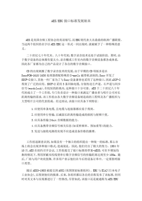
AES/EBU接口标准发展始末AES是美国音频工程协会的英语缩写,而EBU则代表大名鼎鼎的欧洲广播联盟。
当这两个组织的名字以AES/EBU这一形式一同出现时,就被赋予了一种特殊的意义。
二十世纪七十年代末、八十年代初,数字录音技术还处于试验阶段。
那时,由于数字设备的总体拥有量太小,录音棚或工作室内的数字音频设备都各成体系,因此各厂家都为自己的产品设计了各自的数字音频接口。
CD的出现刺激了数字录音技术的发展,由于早期的CD母版多是以SonyPCM-1610/1630处理器搭配特殊的U-matlc磁带机录制的,Sony开发了SDIF-2接口,其他一些厂家为了与Sony设备兼容也采用了这种接口,因此sDlF-2得到了广泛的应用。
SDIF-2采用3条同轴电缆,分别传送左声道、右声道与同步信号(wordclock),在较短的距离内,这种接口十分可靠。
AES于二十世纪八十年代初成立了一个工作组,专门负责设计一种接口来满足广播业者与唱片公司对长距离传输的需求,该工作组由各大数字音频设备制造商的工程师及各广播组织与大型唱片公司的代表组成。
经过商议,该接口应具备下列特征:1.应使用单条电缆,且电缆与连接器都应易于得到。
2.应使用串行传输,以减弱长距离传输造成的损耗与射频干扰。
3.应具备传输24bit音频数据的能力。
4.应具备携带音频信号相关信息(如采样频率、预加重等)的能力。
5.发送与接收电路的实现不应造成设备价格的激增。
工作组逐渐意识到,如果没有一个独立的组织提出一种统一的标准,那么市场上将会出现多种接口格式,造成混乱。
因此,他们付出了极大的努力。
1984年10月,AES在纽约召开会议,工作组提交了接口标准的草案-AES3,可在不增加均衡的情况下,利用屏蔽双绞线使串行数字音频信号的传输距离达到至少100m。
随后,厂商与用户欢欣鼓舞,许多用户表示他们在今后的设备订单中,一定要指明接口类型。
随后AES3-1985被提交到ANSl(美国国家标准组织)、EBU与ElAJ(日本电子工业协会),以得到他们的批准。
SDTI压缩串行数字接口SDTI(QSDI,CSDI,SDDI)接口(SMPTE305M)是由SDI接口(SMPTE259M)发展而来,码率为270 Mbps或360 Mbps,支持净码率在34 Mb/s 以上的高码率可通过多个连接来实现。
SDTI支持多种格式,如DVCPRO,DVCPRO 50,Betacam SX,Digital-S,DVCAM,M-JPEG,MPEG-2等,可用于高于实时的速度传输,如多倍速下载;适用于传统演播室环境,直接支持切换台、录像机和切换矩阵,但不太适应双向传输。
由于SDI接口用于不压缩数字演播室环境,“非编”系统用SDI接口只能实时传输数据。
压缩录像机格式出现后,松下提出了DVCPRO 的CSDI (Compress Serial Digital Interface)接口,索尼提出了DVCAM的QSDI(Quick Serial Digital Interface)接口及Betacam SX的SDDI(Serial Digital Data Interface)接口。
这些接口将压缩数据在一个打包器中打包,同时在原数据中加进错误校正码后即可送出4倍于原容量的数据包,使传输数据速度更快,但是这几种接口相互之间并不兼容,随着接口技术发展的需要,最后统一到SDTI压缩串行数字接口。
SDTI接口应用在“非编”系统中,可高速上载压缩数字视频,SONY的DSR-85P和ES-7非线性编辑站就有此接口,可4倍速上下载DVCAM的压缩数字视频。
SDTI基本上无网络开销,使用与SDI相同的电缆、分配放大器和路由器,电缆长度可达300 m。
AES/EBU及S/PDIF数字音频接口AES/EBU(音频工程师协会/欧洲广播联盟)标准是很常用的专业数字音频标准,其中AES是指AES建议书AES3-1992“双通道线性表示的数字音频数据串行传输格式”,EBU是指EBU发表的数字音频接口标准EBU3250,两者内容在实质上是相同的,但物理上不能互换,后者输入和输出均采用变压器耦合。
AES/EBU是一种通过基于单根绞合线对来传输数字音频数据的串行位传输协议,其全称是Audio Engineering Society/European Broadcast Union(音频工程师协会/欧洲广播联盟),其《双通道线性表示的数字音频数据串行传输格式》,EBU是指EBU 中AES是指AES3-1992标准:发表的数字音频接口标准EBU3250,两者内容在实质上是相同的,统称为AES/EBU数字音频接口。
AES/EBU标准传输数据时低阻抗,信号强度大,波形振幅在3-10V之间,传送速率为6Mbps,抗干扰能力很强,减小了通道间的极性偏移、不平衡、噪音、高频衰减和增益漂移等问题造成的影响,适合较远距离的传输。
整栋大楼内全部以AES/EBU格式电缆进行音频信号的长距离数字化传输,最远的单根信号线传输距离超过400米AES/EBU与网络系统相比的优势1、传输距离更远。
基于局域网的音频传输系统单根网线最长100米,接入路由器后,两点之间最长也就200米的传输距离,超过这个距离就必须使用光纤系统。
而AES/EBU格式在没有中继的情况下,根据AES协会在1995年出台并在2001年更新的AES-3id -1995补充文件规定,最长可以传输超过1000米的距离。
2、传输延时可以忽略。
而AES/EBU格式没有可计的延时,在实际应用中完全可以忽略。
3、系统构成简单可靠4、系统总体造价更低,更为经济选用的LS9/16是06年底新面市的一款专门针对现场扩声应用而设计的数字调音台,在其机背的扩展槽内插入一块MY8-AE的扩展卡,即具备8路AES/EBU信号输出。
而SP2060是一款自带2路AES/EBU信号输入接口,6路模拟输出的多功能音频处理器,可以完成全部的通道分配、均衡、分频和延时等处理功能,并完成数字信号到模拟信号的转换。
该系统中,LS9调音台每两路AES/EBU格式信号输出通过长距离电缆送至功放机柜内的SP2060,实现了数百米的完全无损的高可靠性的数字音频传输。
家庭影院之音响接口详析二、音响系统接口数字音源以数字方式处理声音讯号或数据,常见的数字音源有CD、MD、LD、DVD、DV、DAT、DCC等,根据需要,这些机器可通过数字输出、输入接口与其它的音响器材作讯号或数据的传输。
如在某些CD机上有DIGITAL OUT的端子,便于外接品质较好的DAC(数模转换器)来提升音质;而在大多数的DVD机上会同样的端子,除同样可用于外接高品质DAC外,更重要的是输出Dolby Digital和DTS数字信号,提供给AV 功放(或解码器),以获得5.1声道的环绕声音响效果。
音响系统接口与视频系统一样,分为数字接口与模拟接口,音响器材所用的数字接口包括HDMI、DVI、数字同轴接口SPDIF、光纤接口Toshiba Link以及AES/EBU接口格式等,模拟接口包括S端子、复合视频接口、色差分量接口等。
其中在HDMI、DVI、S端子、复合视频接口、色差分量接口在上面已经介绍过了,如今主要介绍的是音响系统常用的民用数字接口数字同轴接口SPDIF(民用)、光纤接口Toshiba Link(民用)以及AES/EBU(专业)接口格式。
----唯大英雄能本色,是真名士自风流----工具箱名士风流性别:男门派:江湖退隐论坛等级:黄金长老财富等级:稍有积蓄财宝箱:访问我的博客|相册|帖子汇总2楼2008-7-3 16:01:47个人资料短消息回复引用回复Re:家庭影院之音响接口详析1、光纤线TOSLINK光纤线TOSLINK全名Toshiba Link。
这是日本东芝公司较早开发并设定的技术标准,它是以Toshiba+link命名的,在播放器材的背板上有OPTICAL作标识,这就是光纤输出端子。
现在几乎所有的数字影音设备都具备这种格式的接头。
Toslink光纤曾大量应用在普通的中低档CD、LD、MD、DVD机及组合音响上。
Toslink使用光纤传送SPDIF讯号,分两种类型,一般家用的设备都是用标准的接头,而便携式的器材如CD随身听等,则是用与耳机接头差不多大小的迷你光纤接头mini-Toslink。
AES/EBU是一种通过基于单根绞合线对来传输数字音频数据的串行位传输协议,其全称是Audio Engineering Society/European Broadcast Union(音频工程师协会欧洲广播联盟),其中AES是指AES3-1992标准:《双通道线性表示的数字音频数据串行传输格式》,EBU是指EBU 发表的数字音频接口标准EBU3250,两者内容在实质上是相同的,统称为AES/EBU数字音频接口。
AES/EBU标准传输数据时低阻抗,信号强度大,波形振幅在3-10V之间,传送速率为6Mbps,抗干扰能力很强,减小了通道间的极性偏移、不平衡、噪音、高频衰减和增益漂移等问题造成的影响,适合较远距离的传输。
整栋大楼内全部以AES/EBU格式电缆进行音频信号的长距离数字化传输,最远的单根信号线传输距离超过400米AES/EBU与网络系统相比的优势1、传输距离更远。
基于局域网的音频传输系统单根网线最长100米,接入路由器后,两点之间最长也就200米的传输距离,超过这个距离就必须使用光纤系统。
而AES/EBU格式在没有中继的情况下,根据AES协会在1995年出台并在2001年更新的AES-3id -1995补充文件规定,最长可以传输超过1000米的距离。
2、传输延时可以忽略。
而AES/EBU格式没有可计的延时,在实际应用中完全可以忽略。
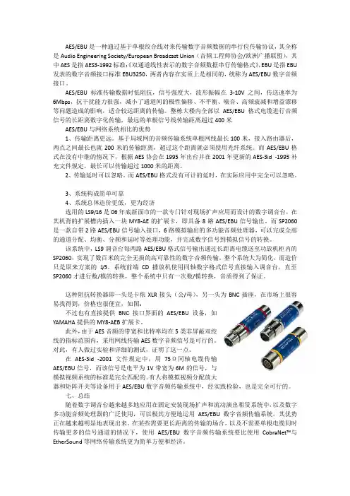
3、系统构成简单可靠4、系统总体造价更低,更为经济AES/EBU信号可采用平衡传输方式(一般应用XLR接头)、也可采用非平衡传输方式(一般应用BNC接头)。
这两种输入/输出接口的阻抗有所不同,但两种传输方式所传输的数据帧结构是一致的,都是遵循AES/EBU帧结构标准的。
在AES/EBU数据帧中包含了时钟信息、音频数据信息、非音频数据三种数据类型。
时钟信息在AES/EUB的信号中,采用“双相位”编码方式,把信号的时钟信息内嵌进了AES/EBU信号流中。
在“双相位”编码方式中,把每一个逻辑“1”和逻辑“0”位所占用的时间称为一个“时间槽”,在逻辑“0”位时,只在“时间槽”的开始与结束处信号进行高、低电平的跳变;在逻辑“1”位时,不仅在“时间槽”的开始和结束处信号进行高、低电平的跳变,同时还要在“时间槽”的中央处再进行一次高、低电平的跳变。
aes ebu标准AES/EBU标准。
AES/EBU标准是一种数字音频接口标准,它由美国音频工程学会(AES)和欧洲广播联盟(EBU)联合制定。
该标准旨在规范数字音频设备之间的连接和通信,以确保高质量的音频传输和兼容性。
首先,AES/EBU标准定义了一种基于双绞线的数字音频接口,使用平衡传输方式。
这种接口可以传输PCM编码的音频信号,采样频率范围从32kHz到192kHz,采样精度为16位或24位。
这种接口的优点在于抗干扰能力强,传输距离远,适用于专业音频设备之间的连接。
其次,AES/EBU标准还规定了数字音频信号的数据格式和传输协议。
数据格式采用了一种双通道的方式,每个通道都包含了音频采样值和同步信息。
传输协议则规定了数据帧的结构和时序,以及错误检测和纠正机制。
这些规定保证了音频数据在不同设备之间的正确传输和解码。
除此之外,AES/EBU标准还包括了对接口连接器和电气特性的规范。
接口连接器采用了XLR型号,这种连接器具有良好的机械性能和电气性能,适合于音频设备之间的连接。
电气特性方面,标准规定了信号的电平范围和传输线的阻抗匹配,以确保音频信号的稳定传输。
总的来说,AES/EBU标准是一项非常重要的音频接口标准,它为专业音频设备的互联互通提供了技术基础。
遵循这一标准,可以保证音频设备之间的兼容性和稳定性,为音频行业的发展提供了有力支持。
在实际应用中,许多专业音频设备,如数字音频工作站、数字混音台、数字音频处理器等,都采用了AES/EBU接口。
这些设备可以通过AES/EBU接口进行数字音频信号的输入和输出,实现高质量的音频录制、处理和传输。
总之,AES/EBU标准对于数字音频设备的互联互通起到了至关重要的作用。
它的制定和推广,促进了数字音频技术的发展和应用,为音频行业的进步做出了重要贡献。
随着数字音频技术的不断发展,AES/EBU标准也将继续发挥其重要作用,推动音频行业朝着更加高品质、高效率的方向发展。
数字音频接口标准一、AES/EBUAES/EBU的全称是Audio Engineering Society/European Bro adcast Union(音频工程师协会/欧洲广播联盟),现已成为专业数字音频较为流行的标准。
大量民用产品和专业音频数字设备如CD机、D AT、MD机、数字调音台、数字音频工作站等都支持AES/EBU。
AES/EBU是一种通过基于单根绞和线对来传输数字音频数据的串行位传输协议。
它无须均衡即可在长达100米的距离上传输数据,如果均衡,可以传输更远距离。
它提供两个信道的音频数据(最高24bit量化),信道是自动计时和自同步的。
它也提供了传输控制的方法和状态信息的表示(“channel status bit”)和一些误码的检测能力。
它的时钟信息是由传输端控制,来自AES/EBU的位流。
它的三个标准采样率是32kHz、44.1kHz、48kHz,当然许多接口能够工作在其它不同的采样率上。
二、S/PDIFS/PDIF的全称是Sony/Philips Digital Interface Format,由于广泛地被采用,它成为事实上的民用数字音频格式标准,大量的消费类音频数字产品如民用CD机、DAT、MD机、计算机声卡数字口等都支持S/PDIF,在不少专业设备上也有该标准的接口。
S/PDIF 格式和AES/EBU有略微不同的结构。
音频信息在数据流中占有相同位置,使得两种格式在原理上是兼容的。
在某些情况下AES/EBU的专业设备和IS/PDIF的用户设备可以直接连接,但是并不推荐这种做法,因为在电气技术规范和信道状态位中存在非常重要的差别,当混用协议时可能产生无法预知的后果。
三、ADATADAT(又称Alesis多信道光学数字接口)。
是美国ALRSTS公司开发的一种数字音频信号格式,因为最早用于该公司的ADAT八轨机,所以就称为ADAT格式。
该格式使用一条光缆传送8个声道的数字音频信号。
摘要就数字音频信号AES/EBU的通道状态进行了专门的介绍,逐字节详细列出了通道状态提供的信息。
关键词AES/EBU 通道数字音频信号AES/EBU也被称作AES3,非平衡传输时称作AES3id,是电视节目制作中广泛使用的一种数字音频格式。
AES/EBU提供了通道状态信息(Channel Status),本文主要就通道状态作专门的介绍。
通道状态描述了AES/EBU相关音频信号的各项技术信息,包括:音频信号的取样频率、字长(量化精度)、通道数,源和目标的字符信息,预加重等。
众所周知,一路AES/EBU 信号包含有2路(或2通道)音频信号,因此一路信号中将有2组通道状态分别与各路音频信号的具体参数。
通道状态由24字节(byte23;每字节又由8比特(bit)组成,分别从比特因此通道状态共有192比特;表结构,表左侧是各字节,表右侧则是左侧各字节内部所提供的逻辑信息。
通道状态随音频数据一同传输。
中,通道状态占用一个比特的位置,图1所示的子帧结构中的比特通道需要连续的192个AES/EBU个帧组成一个音频块的原因。
信息和字节的低位比特,AES/EBU数字音频AES/EBU通道状态介绍中央电视台 甄占京图1图2比特,即字节0的比特0必须跟随同步头为Z 的帧传输,如所示。
需要注意的是,通道状态提供的信息内容仍然在不断修改和完善中,虽然通道状态块的结构已经基本定型,但是各字节内部信息会有所变化和补充,因此不同版本的AES/EBU 通道状态提供的信息会有不同,这里所作介绍依据的是AES3-2003版本,在其之前还有AES3-1985和AES3-1992等不同版本。
下面用表的形式逐字节详细列出了通道状态提供的信息,如后页表2所示。
并且规定:所有为将来预留或没有使用到的字节或比特位都应用逻辑0填充。
通道状态信息提供了数字音频信号各项技术信息,通过特定仪器可以直观准确得读出这些信息的内容,在实际工作中可以有效的利用这些信息,分析和解决系统中出现的各类问题。
AES/EBU 接口标准
AES/EBU 接口标准
AES 和EBU 一起开发的数字音频传输接口标准:
AES/EBU 标准,即AES3-1992,ANSI S4.40-1992,或IEC-958 标准。
它是传输和接收数字音频信号的数字设备接口协议:
规定音频数据必须以2 的补码进行编码。
传输介质是电缆,允许高带宽容量和并行数据字节的串行传输,串行传输16 到20bit 的字节时先传输最低有效位。
串行后的数据流经格式化器加入字节时钟标志以表明每个样值的开始,
格式化后的串行数据流经双向标志码编码器编码后输
出,最后传输的数据流为双相标志码码流。
AES/EBU 编码器框图和并串转换
AES/EBU 接口数据结构
一个音频帧包括两个32 比特的子帧(子帧1 和子帧2),一个子帧只包括一个音频声道的一个样值数据:20 比特、同步数据(子帧的首标):4 个比特、附加数据:4 个比特、有效比特(V):1 比特、用户比特(U):1 比特、声道状态比特(C):1 比特,奇偶校验比特(P):1 比特。
万方数据
万方数据
AES/EBU数字音频接口标准简介
作者:王戎
作者单位:福州广播电视集团技术中心
刊名:
东南传播
英文刊名:SOUTHEAST COMMUNICATION
年,卷(期):2007(10)
1.彭泽安;郭育扬浅谈数字音频接口技术和D/A转换器
2.李清斌浅谈数字音频接口技术及标准 2001(05)
1.汪波.许卫行.WANG Bo.X(U) Wei-hang AES/EBU数字音频的参数及测量技术[期刊论文]-电声技术2005(4)
2.泰克科技(中国)有限公司数字音频和嵌入音频[期刊论文]-现代电视技术2004(10)
3.甄占京数字音频AES/EBU通道状态介绍[期刊论文]-现代电视技术2005(3)
4.陈浩.CHEN Hao AES/EBU数字音频格式在现场扩声系统中的应用[期刊论文]-电声技术2007,31(10)
5.姜路.李臻AES/EBU数字音频传输的测量[期刊论文]-广播电视信息2010(10)
6.张抒数字音频接口及连接[期刊论文]-有线电视技术2001,8(23)
7.汤伟AEs数字音频接口标准及其在音频系统应用的特点[期刊论文]-音响技术2008(3)
8.刘红数字音频信号的传输与测量[期刊论文]-广播电视信息2010(5)
9.谢科.钱泓毅数字音频接口标准简介[期刊论文]-音响技术2002(4)
10.牛睿数字音频技术的兼容与发展[期刊论文]-科技信息2010(16)
本文链接:/Periodical_dncb200710082.aspx。