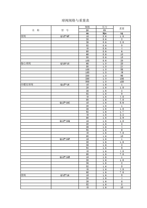
外螺纹球阀
- 格式:pdf
- 大小:307.02 KB
- 文档页数:1
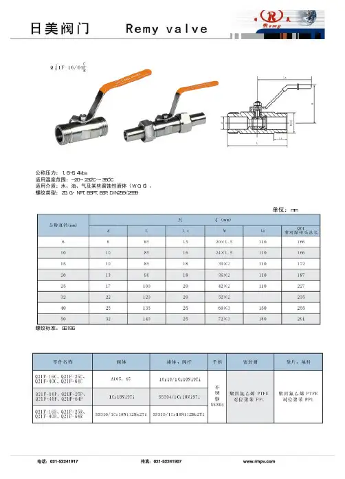
This MSS Standard Practice was developed under the consensus of the MSS Technical Committee 401 and the MSS Coordinating Committee. The content of this Standard Practice is the result of the efforts of competent and concerned volunteers to provide an effective, clear, and non-exclusive specification that will benefit the industry as a whole. This MSS Standard Practice is intended as a basis for common practice by the manufacturer, the user, and the general public. The existence of an MSS Standard Practice does not in itself preclude the manufacture, sale, or use of products not conforming to the Standard Practice. Mandatory conformance is established only by reference in a code, specification, sales contract, or public law, as applicable."Other standards documents referred to herein are identified by the date of issue that wasapplicable to this Standard Practice at the date of issue of this Standard Practice. See AnnexA. This Standard Practice shall remain silent on the applicability of those other standards ofprior or subsequent dates of issue even though applicable provisions may not have changed.References contained herein which are bibliographic in nature are noted as ‘supplemental’ inthe text.”Unless otherwise specifically noted in this MSS SP, any standard referred to herein is identified by the date of issue that was applicable to the referenced standard(s) at the date of issue of this MSS Standard Practice (See Annex A).In this Standard Practice all notes, annexes, tables, and figures are construed to be essential to the understanding of the message of the standard, and are considered part of the text unless noted as "supplemental". All appendices, if included, that appear in this document are construed as "supplemental". Supplemental information does not include mandatory requirements for this Standard Practice.U.S. customary units in this Standard Practice are the standard; metric (SI) units are for reference only.Substantive changes in this 2010 edition are “flagged” by parallel bars asshown on the margins of this paragraph. The specific detail of the changemay be determined by comparing the material flagged with that in theprevious edition.Non-toleranced dimensions in this Standard Practice are nominal, and, unless otherwise specified, shall be considered “for reference only”.Any part of this Standard Practice may be quoted. Credit lines should read `Extracted from MSS SP-110- 2010 with permission of the publisher, the Manufacturers Standardization Society of the Valve and Fittings Industry, Inc.'. Reproduction prohibited under copyright convention unless written permission is granted by the Manufacturers Standardization Society of the Valve and Fittings Industry, Inc.Originally Approved: May 1992Copyright ©, 1992, 1996, 2010 byManufacturers Standardization Societyof theValve and Fittings Industry, Inc.Printed in U.S.A.i标准分享网 免费下载TABLE OF CONTENTSSECTION PAGE1 SCOPE. (1)2 PRESSURE-TEMPERATURE RATINGS. (1)3 MATERIALS. (2)4 DESIGN. (2)5 DIMENSIONS (3)6 MARKING (4)7 TESTING (4)TABLE1 Port Sizes for Ball Valves (6)2 Shell Test Duration (Visual Test Methods) (7)3 Seat Test Duration (7)FIGURE1 Examples of Valve Types (8)2 Typical Nomenclature for Ball Valve Parts (9)ANNEXA Referenced Standards and Applicable Dates (10)iiiii127 Park Street, NE • Vienna, VA 22180-4602 • 703-281-6613 • FAX 703-281-6671 • • e-mail:info@EXECUTIVE DIRECTOR : Robert F. O’NeillERRATA SHEET FOR MSS SP-110-2010BALL VALVES THREADED, SOCKET-WELDING, SOLDER JOINT,GROOVED AND FLARED ENDSAugust 23, 2010Note the following correction:1. Page 2, Section 3.3, Other Parts . Under “Caution for Users,” the second sentenceshould read “For guidance, see ASME B31.3, Appendix F.”This Errata Sheet is included in the Standard Practice.Future printing of the Standard Practice will include this revised data.PRESIDENT: J.V. Ballun – Val-Matic Valve & Mfg. Corp.VICE PRESIDENTS: T.J. Hannafin – KITZ Corp. of America M.A. Clark – NIBCO, Inc.TREASURER: G.M. Johnson – United ValveManufacturers Standardization Society of the Valve And Fittings Industry, Inc.标准分享网 免费下载1. SCOPE1.1 General1.1.1 This Standard Practice covers round opening, full, regular and reduced port metal ball valves.1.1.2 End connections covered herein are threaded, socket-welding, solder joint, grooved and flared end in nominal pipe sizes ¼ through 4 inch.1.1.3 These valves are intended for on-off operation and should be used for modulating or throttling service only when recommended by the manufacturer.1.1.4 This Standard Practice covers ball valves of the following materials:Carbon SteelAlloy SteelsStainless SteelsGray Cast IronDuctile IronMalleable IronCopper Alloy1.2References1.2.1 Standards and specifications adopted by reference in this Standard Practice and names and addresses of the sponsoring organizations are shown in Annex A. It is not considered practical to refer to a specific edition of each of the standards and specifications in the individual references. Instead, the specific edition references are included in Annex A. A product made in conformance with the edition reference applicable during the time of manufacture, and in all other respects conforming to this Standard Practice, will be considered to be in conformance even though the edition reference may be changed in a subsequent revision of this Standard Practice.1.3 Description of Valve Types and Parts1.3.1 Examples of some valve types are shown inFigure 1. When variations of these basic types areused, they shall be named by the manufacturer.1.3.2 The names of basic valve parts are given inFigure 2.Note: The valve sketches shown in Figures 1 and2 are for the purpose of illustration andnomenclature only and do not represent or endorseany manufacturer's product.2. PRESSURE-TEMPERATURE RATINGS2.1 Basis of RatingsThe pressure-temperature ratings for assembled valves shall be determined by the material of thebody, seats, stem seals, end connections or any other component or type of construction that would be restrictive. Manufacturers should be consulted for exact ratings applicable for a particular material or type. Pressure-temperature ratings of steel valves, shall not exceed those specified in ASME B16.34, where applicable.2.2 Solder End RatingsRatings of solder-end connections shall not exceedthe limitations of ASME B16.18. It shall be theresponsibility of the user to select a solder composition that is compatible with the service conditions.2.3 Cold Working Pressure (CWP)The cold working pressure rating of the valveshell and components is the maximum allowablenon-shock pressure at 100ºF. The maximum working pressure at any other temperature shallnot exceed this rated pressure.BALL VALVESTHREADED, SOCKET-WELDING, SOLDER JOINT, GROOVED AND FLARED ENDS123. MATERIALS 3.1 Valve Body3.1.1 Steel Steels shall be made to ASTM, AISI, or other standards for which mechanical and chemical data are available. The valve pressure boundary parts and bolts shall be made from metals that have the allowable stress established for the temperature range for which the valve is designed. This can be metals that the ASME has established allowable design stress at temperatures the valve will be used at or stress established by testing in accordance with the rules of ASME. Consideration of welding characteristics shall be given to those steels intended for socket weld end valves.3.1.2 Iron Casting for Threaded End Valves Cast iron shall conform to ASTM A126, Class B or C. Malleable iron castings shall conform to ASTM A47 (Grades 32510, 35018) or ASTM A197. Ductile iron castings shall conform to ASTM A395 or ASTM A536 (Grades 60-40-18 or 65-45-12).3.1.3 Nonferrous Alloys Non-ferrous materials shall be made to ASTM, CDA, or other standards for which mechanical and chemical data are available.3.2 BoltingPreferred bolting materials are as specified in ASME B16.34 Table 1, Group 4. If non-listed materials are used, the valve manufacturer shall be prepared to certify that the products are at least equally suitable for the intended use.3.3 Other PartsParts, for example stems, glands, packing nuts, balls, seats, and seals shall be of materials suitable for the pressure-temperature rating.Caution for Users: Service conditions other than pressure-temperature may affect suitability of the valve materials. For guidance, see ASME B31.3, Appendix E. 4. DESIGN 4.1 GeneralThe valve design and materials of construction shall be structurally suitable for their stated pressure ratings and temperature limits. Any additional metal thickness above the thickness necessary to contain pressure such as may be needed for assembly stresses, valve closing stresses, shapes other than circular, stress concentrations, and corrosion allowances, shall be determined by the manufacturer.4.2 Joints4.2.1 The design of the valve shall be such as to provide against detrimental distortion under hydrostatic test conditions, assembly stresses, closing stresses, pipe reaction stresses, or when rated pressure is applied across a closed valve.4.2.2 Bolting shall be threaded in accordance with ASME B1.1.4.2.3 Top entry valve bonnet joints shall be designed as follows:4.2.3.1 Flanged bonnet bolting shall be such that a direct nominal stress resulting from the maximum working pressure acting on an area bounded by the effective outside periphery of the bonnet seal shall not exceed the allowable bolt stress values listed in ASME Boiler and Pressure Vessel Code, Section VIII, Division 1; not to exceed 20,000 psi. For non-listed bolt materials, the allowable bolt stress shall be taken as 25% of the yield strength, not to exceed 20,000 psi.4.2.3.2 Threaded bonnet or cover joints shall have a thread shear area that satisfies the following:P(Ag/As) ≤ .6Sawhere:P = Valve cold working pressure, psig.标准分享网 免费下载Ag = Area bounded by the effective outside periphery of a gasket or O-ring, or other seal effective periphery, except that in the case of a ring-joint, the bounded area is defined by the pitch diameter of the ring, square inches.As = Total effective thread shear area, square inches.Sa = Allowable minimum body/bonnet stress, from ASME Boiler and Pressure Vessel Code, Section VIII, Division 1, not to exceed 20,000 psi. For non-listed materials, the allowable stress shall be the lesser of 25% of the minimum tensile strength, or 67% of the minimum yield strength, not to exceed 20,000 psi.4.2.4 Valves having flanged body joints which split the valve either perpendicular to or at an angle with the piping are subject to piping loads. Bolting in these cases shall be such that a direct tensile stress shall not exceed 7/9 of the allowable stress listed in ASME Boiler and Pressure Vessel Code, Section VIII, Division 1, not to exceed 20,000 psi. For non-listed bolting materials, the allowable bolt stress shall be taken as 25% of the yield strength not to exceed 20,000 psi.4.2.5 Valves of a one-piece end entry type shall be designed so that the body insert is sufficient to withstand the full differential pressure permissible for the valve.4.2.6 Threaded body joints exposed to piping loads shall satisfy the following thread shear area requirements:P(Ag/As) ≤ .47Sawhere: P, Ag, As, and Sa are as defined in Section 4.2.3.2.4.3 End Connections4.3.1 Threaded pipe ends shall have taper pipe threads in accordance with ASME B1.20.1.4.3.2 Socket dimensions of socket weldingends shall be in accordance with ASME B16.11.4.3.3 Solder cup dimensions of solder jointends shall be in accordance with ASME B16.18.4.3.4 Grooved ends shall have groove dimensionsin accordance with MIL-P-11087G.4.3.5 Flared ends shall be in accordance withASME B16.26.4.4 Stems4.4.1 To prevent removal of the stem while thevalve is pressurized, the valve shall be designedso that the stem seal retainer assembly (gland)alone does not retain the stem.4.4.2 In those cases where service conditionsrequire electrical continuity between the stemand body, the purchaser must so specify.4.5 Stem Packing4.5.1 The valve shall have provisions foradjustment of a gland or packing nut in order toobtain a seal at the stem packing. The exception isfor valves with elastomeric stem seals, whereadjustment is not possible.4.6 Position Indication4.6.1 The valve shall have a positive means ofindication of ball port position. If the handle is theonly means of indication (i.e., valve not equippedwith position indication), it shall be designed suchthat the handle cannot be assembled to indicateother than the position of the ball port.5. DIMENSIONS5.1 Valve port diameters for full port, regular port,and reduced port are defined in Table 1. Allcomponents forming the flow stream shall have aninside diameter no smaller than as indicated.347.1.3 For valves having CWP no greater than 1500 psig, the manufacturer may, as a substitute for the test specified in Section 7.1.1 test each valve using gas at a minimum pressure of 80 psig for a duration of not less than set forth in Table 2. In order to exercise this option, the manufacturer must sample production lots to ASQ Z1.4, Level II, 0.4 AQL using the test specified in Section 7.1.1.7.1.4 For reduced port, end entry valves having one-piece bodies in nominal pipe sizes 2 and smaller that have a CWP no greater than 2000 psig, the manufacturer may, as a substitute for the test specified in Section 7.1.1 test each valve using gas at a minimum pressure of 80 psig for a duration of not less than set forth in Table 2. In order to exercise this option, the manufacturer must sample production lots to ASQ Z1.4, Level II, 0.4 AQL using the test specified in Section 7.1.1.7.1.5 The ball shall be in such a position during the shell test as to assure full pressurization of the valve shell.7.1.6 When tested with a liquid, the valve exterior shall show no visible leakage. When tested with a gas, the valve shall show no visible leakage when immersed in water or coated with a leak detection solution.7.1.7 Visually detectable leakage through pressure boundary walls is not acceptable. Leakage through adjustable stem packing during testing shall not be cause for rejection. The stem packing or stem seals shall be capable of retaining pressure at least equal to the rated cold working pressure of the valve without visible leakage.7.1.8 When volumetric loss testing devices are used the valve manufacturer must be able to demonstrate that leakage sensitivity of the device produces results that are equivalent to those which are acceptable when visual examination methods are employed.6. MARKING6.1 Ball valves shall be marked in accordance withMSS SP-25.6.2 Copper alloy ball valves made with copperalloy components including end pieces or caps,stem, ball (which may be either plated or unplated),and the manufacturer's standard seat material forthose valves do not need trim marking per Section7.1.3 of MSS SP-25.6.3 Copper alloy ball valves manufactured withoptional trim components for ball, stem, or seatsshall be marked to indicate the optional ball, stem,or seat per MSS SP-25, or as identified by themanufacturer's figure or model number.7. TESTING7.1 Shell Test7.1.1 Each valve, except as noted in Sections7.1.2 thru 7.1.4, shall be given a shell test, at apressure of 1.5 times the CWP, and rounded off tothe next higher 25 psi. The test fluid shall be air,gas, water, kerosene, or liquids with a viscosity nogreater than that of water. The test fluidtemperature shall be below 100ºF. The duration ofthe test shall be as set forth in Table 2.7.1.2 For valves having CWP no greater than1000 psig, the manufacturer may, as a substitutefor the test specified in Section 7.1.1 test eachvalve using gas at a minimum pressure of 80 psigfor a duration of not less than that set forth inTable 2. In order to exercise this option, themanufacturer must be able to certify that aproduction sample of the valve model so testedhas been subjected to a hydrostatic shell test of atleast 2.5 times CWP with no detrimentaldistortion as evidenced by a subsequent seat test.标准分享网 免费下载7.2 Seat Test7.2.1 Following the shell test, each valve shall be given a closure seat test. At the manufacturer’s option, this test may be either a hydrostatic closure test at a pressure no less than 110% of the 100ºF seat pressure rating or a gas closure test at a minimum pressure of 80 psig. The duration of the test shall be as set forth in Table 3.7.2.2 The test pressure shall be applied successively on each side of the closed valve. As an alternate method for the 80 psig minimum gas test, the pressure may be applied inside the body cavity with the ball closed and both sides open for inspection. The method of seat leakage testing on each seat shall result in a filled or pressurized cavity between the seats to assure that no seat leakage can escape detection because of gradual and incomplete pressurization or filling of the cavity during the test duration.7.2.3 Valves marked as one-way valves requirea closure test only in the direction of the flow.7.2.4 There shall be no visible leakage past the seat for the duration of the test for valves with resilient (polymeric or elastomeric) seats.7.2.4.1 The term “no visible leakage” applied toa hydrostatic test liquid is defined as a leak rate that will produce no visible weeping or formation of drops at the test pressure and for the duration of the test.7.2.4.2 The term “no visible leakage” applied to air or gas testing is defined as a leak rate that will produce no visible formation of bubbles in a water immersion test or after application of a leak detection fluid at the test pressure and for the duration of the test.7.2.4.3 For automatic leak detection methods, this definition shall be considered equivalent to a leak rate no greater than 4.1x10^-5in^3/sec (6.7x10^-4ml/sec) with a pressure differential of 80 to 100 psig (5.5 to 6.9 bar) for application to valves NPS 8 and smaller.7.2.5 The maximum allowable leakage rate on each seat of non-resilient seated, except metal-seated, valves for the duration of the test shall be 2/10of a standard cubic foot of gas per hour per inch of nominal valve size, or a maximum of 1.22 cubic inches of hydrostatic media per hour per inch of nominal valve size, at the test pressure specified in Section 7.2.1.7.2.6 The maximum allowable leakage rate on each seat of metal-seated valves for the duration of the test shall be 4/10 of a standard cubic foot of gas per hour per inch of nominal valve size, or a maximum of 2.44 cubic inches of hydrostatic test media per hour per inch of nominal valve size at the test pressure specified in Section 7.2.1.7.2.7 When volumetric loss testing devices are used, the valve manufacturer must demonstrate that leakage sensitivity of the device produces results that are equivalent to or better than those which are acceptable when visual examination methods showing no leakage are employed.7.3 System Hydrostatic TestsIf valves conforming to this Standard Practice are subjected to hydrostatic testing of systems with the valve in the closed position at a pressure greater than the CWP rating, such testing shall be the responsibility of the user.56TABLE 1Port Sizes for Ball ValvesValve Size (NPS) DiameterFull Port (1) InchesRegular Port (1)Inches Reduced Port (1)Inches ¼.25 not specified not specified 38.37 not specifiednot specified½ .50 .37 .31 ¾ .75 .56 .46 1 1.00 .75 .621¼ 1.25 .93 .77 1½ 1.50 1.12 .93 2 2.00 1.50 1.24 2½2.501.871.553 3.00 2.25 1.864 4.00 3.00 2.48Tolerance: Undersize: .06 inchesOversize: No limit specified(1)For pressures in excess of 1500 psig, Annex A of ASME B16.34 may be used forguidance with regard to the minimum inside diameter of full port valves.标准分享网 免费下载TABLE 2Shell Test Duration(Visual Test Methods)ValveCWP RatingMaximum Shell Test Pressure (minimum) Shell Test Duration: (e) Seconds (minimum)AIR HYDROSTATIC (a) AIR HYDROSTATICpsig psig psig Valve Size (NPS) Valve Size(NPS)¼ - 4¼ - 2 2½ - 4 1000 80 (b) 1.5 x CWP 5 15 601500 80 (c) 1.5 x CWP 5 15 602000 80 (d) 1.5 x CWP5 15 60 Notes: (a) Round off to next higher 25 psi increment(b) Refer to Section 7.1.2(c) Refer to Section 7.1.3(d) Refer to Section 7.1.4 (e) Time duration is period of inspection after valve is fully prepared and under shell test pressure.TABLE 3Seat Test DurationValveSize(NPS)Seat Test Duration: (a) Seconds (minimum) Air Hydrostatic ¼ - 25 15 2½ - 45 30 Notes: (a) Time duration is period of inspection after valve is fully preparedand under full seat test pressure.FIGURE 1Examples of Valve Types(Design Details not Shown)These illustrations are not intended to limit design, or to indicate any preferred design.Figure 1A One-Piece Body Construction Figure 1BTwo-Piece BodyConstructionFigure 1CThree-Piece BoltedBody Construction(Solder X Threaded End Shown)FIGURE 2Typical Nomenclature for Ball Valve PartsThese illustrations are not intended to limit design, or to indicate any preferred design. PART NAME 1. Handle 2. Stem 3. Gland 4. Stem Seal * 5.Thrust Washer 6. Ball 7. Seat 8. Body 9. End Cap 10. Body Seal * 11. Body Insert 12. Handle Nut 13. Bonnet 14. Bonnet Seal * 15. Trunnion * 16. Trunnion Bushing 17. Body Bolting 18. Bonnet Bolting 19. Packing Nut * Not illustratedANNEX AReferenced Standards and Applicable DatesThis Annex is an integral part of this Standard Practice and is placed after the main text for convenience. Standard Name DescriptionASME; ANSI/ASMEB1.1-2003 (R2008) Unified Inch Screw Threads, (UN and UNR Thread Form)B1.20.1-1983 (R2006) Pipe Threads, General Purpose (Inch)B16.11-2009 Forged Fittings, Socket-Welding & ThreadedB16.18-2001 (R2005) Cast Copper Alloy Solder Joint Pressure FittingsB16.26-2006 Cast Copper Alloy Fittings for Flared Copper TubesB16.34-2004 Valves Flanged, Threaded and Welding EndB18.2.1-1996 (R2005) Square and Hex Bolts and Screws, Inch SeriesB18.2.2-1987 (R2005) Square and Hex NutsB18.3-2003 (2008) Socket Cap, Shoulder, and Set Screws, Hex and Spline Keys (Inch Series)PipingB31.3-2008 ProcessBPVC-VIII, Div.1-2007 Boiler and Pressure Vessel Code, Section VIII, Division 1, Rules for Constructionof Pressure VesselsASQ; ANSI/ASQZ1.4-2008 Sampling Procedures and Tables for Inspection by AttributesASTMSpecification for Ferritic Malleable Iron CastingsA47/A47M-99(2009) StandardA126-04 Standard Specification for Grey Iron Castings for Valves, Flanges, and PipeFittingsSpecification for Cupola Malleable IronA197/A197M-00(2006) StandardA395/A395M-99(2009) Standard Specification for Ferritic Ductile Iron Pressure-Retaining Castings forUse at Elevated TemperaturesSpecification for Ductile Iron CastingsA536-84(2009) StandardMilitary SpecificationsMIL-P-11087G-1994 Pipe, Steel: Grooved or Plain EndMSSSP-25-2008 Standard Marking System for Valves, Fittings, Flanges, and UnionsSP-96-2001 (R 2005) Guidelines on Terminology for Valves and FittingsANNEX A (Continued)Referenced Standards and Applicable Dates Standards and Specifications of the following organizations appear on the previous page.ANSI American National Standards Institute, Inc.25 West 43rd Street, Fourth FloorNew York, NY 10036-7406ASME American Society of Mechanical EngineersThree Park AvenueNew York, NY 10016-5990ASTM ASTM International100 Barr Harbor DriveWest Conshocken, PA 19428-2959ASQ The American Society for Quality, Inc.600 North Plankton AvenueMilwaukee, WI 53203-2914MSS Manufacturers Standardization Society of the Valve and Fittings Industry, Inc.127 Park Street, NEVienna, VA 22180-4602Organizations referenced in this Standard Practice without a specific standard referenced. AISI American Iron and Steel Institute1140 Connecticut Ave., NW, Suite 70520036-4700Washington,DCCDA Copper Development Association, Inc.Avenue260MadisonNew York, NY 10016-2401Listing of MSS Standard PracticesTITLESP-6-2007 Standard Finishes for Contact Faces of Pipe Flanges and Connecting-End Flanges of Valves and FittingsSP-9-2008 Spot Facing for Bronze, Iron and Steel FlangesSP-25-2008 Standard Marking System for Valves, Fittings, Flanges, and UnionsSP-42-2009 Corrosion Resistant Gate, Globe, Angle and Check Valves with Flanged and Butt Weld Ends (Classes 150, 300 & 600)SP-43-2008 Wrought and Fabricated Butt-Welding Fittings for Low Pressure, Corrosion Resistant Applications (Incl. 2010 Errata Sheet)SP-44-2010 Steel Pipeline FlangesSP-45-2003 (R 2008) Bypass and Drain ConnectionsSP-51-2007 Class 150LW Corrosion Resistant Flanges and Cast Flanged FittingsSP-53-1999 (R 2007) Quality Standard for Steel Castings and Forgings for Valves, Flanges, and Fittings and Other Piping Components - Magnetic ParticleMethodExamination2007) Quality Standard for Steel Castings and Forgings for Valves, Flanges, and Fittings and Other Piping Components - RadiographicSP-54-1999 (RExamination MethodSP-55-2006 Quality Standard for Steel Castings for Valves, Flanges, Fittings, and Other Piping Components - Visual Method for Evaluation of IrregularitiesSurfaceSP-58-2009 Pipe Hangers and Supports - Materials, Design, Manufacture, Selection, Application, and InstallationSP-60-2004 Connecting Flange Joint Between Tapping Sleeves and Tapping ValvesSP-61-2009 Pressure Testing of ValvesSP-65-2008 High Pressure Chemical Industry Flanges and Threaded Stubs for Use with Lens GasketsValvesSP-67-2002a ButterflySP-68-1997 (R 2004) High Pressure Butterfly Valves with Offset DesignSP-69-2003 Pipe Hangers and Supports - Selection and Application (ANSI-approved American National Standard)SP-70-2006 Gray Iron Gate Valves Flanged and Threaded EndsSP-71-2005 Gray Iron Swing Check Valves, Flanged and Threaded EndsSP-72-2010 Ball Valves with Flanged or Butt-Welding Ends for General ServiceforHigh-Test, Wrought, Butt-Welding FittingsSP-75-2008 SpecificationSP-77-1995 (R 2000) Guidelines for Pipe Support Contractual Relationships - Relationships and Responsibilities of the Pipe Hanger Contractor with the Purchaser's Engineer or the Pipe Fabricator and/or ErectorSP-78-2005a Gray Iron Plug Valves Flanged and Threaded EndsSP-79-2009 Socket Welding Reducer InsertsSP-80-2008 Bronze Gate, Globe, Angle, and Check ValvesBonnetless, Flanged Knife Gate ValvesSP-81-2006a StainlessSteel,SP-83-2006 Class 3000 Steel Pipe Unions Socket Welding and ThreadedSP-85-2002 Gray Iron Globe & Angle Valves Flanged and Threaded EndsSP-86-2009 Guidelines for Metric Data in Standards for Valves, Flanges, Fittings, and ActuatorsValvesSP-88-2010 DiaphragmSP-89-2003 Pipe Hangers and Supports - Fabrication and Installation PracticesSP-90-2000 Guidelines on Terminology for Pipe Hangers and SupportsSP-91-2009 Guidelines for Manual Operation of ValvesSP-92-1999 MSS Valve User GuideSP-93-2008 Quality Standard for Steel Castings and Forgings for Valves, Flanges, Fittings, and Other Piping Components - Liquid PenetrantMethodExaminationSP-94-2008 Quality Standard for Ferritic and Martensitic Steel Castings for Valves, Flanges, Fittings, and Other Piping Components - UltrasonicMethodExaminationSP-95-2006 Swage(d) Nipples and Bull PlugsSP-96-2001 (R 2005) Guidelines on Terminology for Valves and FittingsSP-97-2006 Integrally Reinforced Forged Branch Outlet Fittings - Socket Welding, Threaded, and Buttwelding EndsSP-98-2001 (R 2005) Protective Coatings for the Interior of Valves, Hydrants, and FittingsSP-99-1994 (R 2005) Instrument ValvesSP-100-2009 Qualification Requirements for Elastomer Diaphragms for Nuclear Service Diaphragm ValvesSP-101-1989 (R 2001) Part-Turn Valve Actuator Attachment - Flange and Driving Component Dimensions and Performance CharacteristicsSP-102-1989 (R 2001) Multi-Turn Valve Actuator Attachment - Flange and Driving Component Dimensions and Performance CharacteristicsSP-104-2003 Wrought Copper Solder Joint Pressure FittingsSP-105-1996 (R 2005) Instrument Valves for Code ApplicationsSP-106-2003 Cast Copper Alloy Flanges and Flanged Fittings Class 125, 150 and 300SP-108-2002 Resilient-Seated Cast-Iron Eccentric Plug ValvesSP-109-1997 (R 2006) Welded Fabricated Copper Solder Joint Pressure FittingsSP-110-2010 Ball Valves Threaded, Socket-Welding, Solder Joint, Grooved and Flared EndsSP-111-2001 (R 2005) Gray-Iron and Ductile-Iron Tapping SleevesSP-112-1999 (R 2004) Quality Standard for Evaluation of Cast Surface Finishes - Visual and Tactile Method. This SP must be used with a 10-surface, three dimensional Cast Surface Comparator, which is a necessary part of the standard. Additional Comparators available separately.SP-113-2001 (R 2007) Connecting Joint between Tapping Machines and Tapping ValvesSP-114-2007 Corrosion Resistant Pipe Fittings Threaded and Socket Welding Class 150 and 1000SP-115-2006 Excess Flow Valves, 1 1/4 NPS and Smaller, for Fuel Gas ServiceSP-116-2003 Service-Line Valves and Fittings for Drinking Water SystemsSP-117-2006 Bellows Seals for Globe and Gate ValvesSP-118-2007 Compact Steel Globe & Check Valves - Flanged, Flangeless, Threaded & Welding Ends (Chemical & Petroleum Refinery Service)SP-119-2003 Factory-Made Wrought Belled End Socket-Welding FittingsSP-120-2006 Flexible Graphite Packing System for Rising Stem Steel Valves - Design RequirementsSP-121-2006 Qualification Testing Methods for Stem Packing for Rising Stem Steel ValvesSP-122-2005 Plastic Industrial Ball ValvesSP-123-1998 (R 2006) Non-Ferrous Threaded and Solder-Joint Unions for Use with Copper Water TubeSP-124-2001 Fabricated Tapping SleevesSP-125-2010 Gray Iron and Ductile Iron In-Line, Spring-Loaded, Center-Guided Check ValvesSP-126-2007 Steel In-Line Spring-Assisted Center Guided Check ValvesSP-127-2001 Bracing for Piping Systems Seismic-Wind-Dynamic Design, Selection, ApplicationSP-128-2006 Ductile Iron Gate ValvesSP-129-2003 (R 2007) Copper-Nickel Socket-Welding Fittings and UnionsSP-130-2003 Bellows Seals for Instrument ValvesSP-131-2004 Metallic Manually Operated Gas Distribution ValvesSP-132-2010 Compression Packing Systems for Instrument ValvesSP-133-2005 Excess Flow Valves for Low Pressure Fuel Gas AppliancesSP-134-2006a Valves for Cryogenic Service Including Requirements for Body/Bonnet ExtensionsSP-135-2006 High Pressure Steel Knife Gate ValvesSP-136-2007 Ductile Iron Swing Check ValvesSP-137-2007 Quality Standard for Positive Material Identification of Metal Valves, Flanges, Fittings, and Other Piping ComponentsSP-138-2009 Quality Standard Practice for Oxygen Cleaning of Valves & FittingsSP-139-2010 Copper Alloy Gate, Globe, Angle, and Check Valves for Low Pressure/Low Temperature Plumbing Applications(R YEAR) Indicates year standard reaffirmed without substantive changes Price List Available Upon RequestMSS is an ANSI-accredited American National Standards developer. A number of former MSS Standard Practices have been adopted and published by other developers as American National Standards. In order to maintain a single source of authoritative information, MSS has withdrawn its Standard Practices in such cases.。

(一)阀门产品品种术语-valve英汉互译之杨若古兰创作阀门 valve通用阀门 General valve球阀 Ball valve槽车球阀 Tank Lorry Ball ValvesCQ螺纹球阀 CQ Thread Ball Valves法兰球阀 Flange Ball Valves衬里球阀 Lining Ball Valves闸阀 Gate valve楔式闸阀 Wedge Gate Valves法兰闸阀 Flange Gate Valves排渣闸阀 Scum Gate Valves薄型闸阀 Thin Gate Valves水封闸阀 Water Seal Gate Valves电动楔式闸阀 Electric Actuated Wedge Gate Valve平板闸阀 Flat Gate Valve单闸板平板闸阀 Single Disc Flat Gate ValvesElectric Double Disk Parallel Gate Valves电动平行式双闸板闸阀Double Disc Flat Gate Valves 双闸板平板闸阀Double Disk Parallel Gate Valves平行式双闸板闸阀截止阀 Globe valveAngle Globe valves 角式截止阀Angle Type Globe Valves 门角式截止阀Electric Actuated Stop Valves 电动截止阀Flange Globe Valves 法兰截止阀Lining Globe Valves衬里截止阀Oblique Stop Valves 直流式截止阀???????Plunger Globe Valves 柱塞截止阀Magnetic Co-operate Globe Valves磁耦合截止阀止回阀Check valve旋启式止回阀 Swing Check Valves 对夹式止回阀 Wafer Check Valves蝶式缓冲止回阀 Butterfly Type Non-slam Check蝶式缓冲止回阀 Butterfly Type Non-slam Check升降式止回阀 Lift Check Valves衬里止回阀 Lining Check Valves微阻缓闭止回阀 Tiny Drag Slow Shut Check Valves立式止回阀 Vertical Lift Check Valves蝶阀 Butterfly Valve对夹蝶板阀 Wafer plate valves衬里碟阀 Lining Butterfly Valves蜗轮传动蝶阀 Butterfly Valves with Gear ActuatorWafer Type Butterfly Valves with Rubber Itning对夹式衬胶蝶阀调节阀 Control Valve电站阀 Power Station ValveHigh Temperature Pressure Power Station Gate Valves 高温高压电站闸阀High Temperature Pressure Power Station Globe Valves 高温高压电站截止阀节流阀 Throttle valve Angle Throttle Valves 角式节流阀隔膜阀 diaphragm valve旋塞阀 plug valve平安阀 safety valve管道平安阀 Piping Safety Valves回转阀 rotary valve减压阀 pressure reducing valve减速阀 Deceleration valves泄压阀 Decompression valves蒸汽疏水阀 Automatic steam trap valve组合阀 Combination valves气动阀门pneumatic valve气动阀pneumatic valves气动件Pneumatic component脚踏阀foot operated valve气动气管 pneumatic gas tube气动手指 pneumatic finger流量控制阀flow control valve机械阀mechanical valve针形阀 Pintle valve仪表阀 Gauge Valves仪表针形截止阀 Meter Needle Type Globe Valves空气阀门 Air valvesAsh valves 排灰阀Aspirating valves 吸(抽)气阀Auxiliary valves 辅助(副)阀Balance valves 平衡阀Bellows valves 波纹管阀Blowdown valves 泄料(放空,排污)阀Brake valves 制动阀Buttwelding valves 对焊连接阀Cock 二通气动元件pneumatic components气源处理器air treatment履行元件execute component控制元件control component辅助元件auxiliary component气缸cylinders尺度气缸standard cylinders薄型气缸compact cylinder气动接头 tube connector气动件 pneumatic elementPU管 PU tubeCulvert valves 地下管道阀Double Opening Exhaust Valves 双口排气球Drainage valves 排水阀Emergeny Cut-off Valves 紧急切断阀Exhaust valves 排气阀Free Float Type Steam Trap 浮球式疏水阀Hand-operated valves 手动阀Hard Seal Butterfly Valves 金属密封碟阀Hydraulic relay valves 液压继动阀Limit valves 限位阀Lining Cock 衬里二通Lining T-Cock Valves 衬里三通旋塞阀Liquid Indicator 液位计LPG Pipe Fitting 液化气管件Manual Oil Pumps Valves 手摇油泵阀Parallel Slide Valves 浆液阀Plunger valves 柱塞阀Pressure valve 压力(増压)阀Quick Draining Valves 快速排污阀Restrictor Valves 过流阀(或节流阀)电磁阀Solenoid valveSolenoid valves电磁阀Single Opening Exhaust Valves 单口排气球Strainer 过滤器T-Cock 三通Throttle Valves 节流阀Triple (tee) valves 三通阀Two-way valves 二通阀Waste Valves 排污箱(阀)Y Type and Cylinder Filters Y型筒型过滤器(二)阀门拆卸零部件术语中英对照阀体 body 阀体 valve body阀盖 bonnet阀盖衬套 bonnet bush阀盖垫片 bonnet gasket气动配件pneumatic parts阀瓣 Disc阀箱 valve box阀箱;阀限位器 valve guard气动元件Pneumatic component气动安装Pneumatic equipment阀座 Seat ring 阀座 valve carrier阀座 valve seat(body seat)阀座;阀盘 valve seat电磁阀阀座solenoid valve seat阀座环 seat ring阀座密封嵌条 sealing strip for valve seat阀杆 Stem阀杆螺母 Yoke bushing Yoke nut阀杆环 stem ring法兰 flange填料 Packing填料垫 Packing seat密封件 Sealing圆柱齿轮传动安装 Cylindrical gear actuator圆锥齿轮传动安装 Conical gear actuator挡板 damper导阀 Pilot valve导向套 Valve guide disc guide弹簧座 Spring plateAxis Guide 轴套Ball 球、球芯Ball seat 密封圈Blowdown Sealing Face 启、阀件密封面nut 螺母Screw 螺栓Spring 弹簧Wedge Disc 闸板(三)阀门技术规范英术语对照技术规范 Technique norm公称通径 Nominal diameter口径 bore 公称压力 Nominal pressure工作温度 Operating temperature工作温度 Working temperature工作压差 Operating differential pressure工作压力 Operating pressure工作压力 Working pressure工作背压 Operating back pressure关闭压力 Lockup pressure开阀过冷度 Subcooled temperature of open valve 开阀温度 Opening valve temperature开启高度 Lift壳体试验 Shell test壳体试验压力 Seal test pressure连接槽尺寸 Dimension of connecting channel连接尺寸 Conncetion cimension连接方式 Type of connection流道面积 Flow area流道直径 Flow diameter流量孔板 flow orifice plate流量特性 Flow characteristics流量特性偏差 Flow characteristics derivation漏汽量 Steam loss密封面 Sealing face密封试验 Seal test密封试验压力 Seal test pressure上密封 Back seat上密封试验 Back seal test适用介质 Suitable medium适用温度 Suitable temperature无负荷漏汽量 No-load steam loss无负荷漏汽率 Rate of no-load steam loss绝对静偏差 Relative static characteristics derivation绝对流量特性偏差 Relative flow characteristics derivation绝对压力特性偏差 Relative pressure characteristics derivation 压力特性 Pressure characteristics压力特性偏差 Pressure characteristics derivation压力增加系数 Pressure increasing ratio有负荷漏汽量 Load steam loss有负荷漏汽率 Rate of load steam loss次要外形尺寸 Prime out-form dimensions次要功能参数 Specifeca tion speeification最大过冷度 Maximum subcoold temperature最大流量 Maximum flow rate最大压差 Maximum differential pressure最低工作压力 Minimum operating pressure最高背压率 Maximum rate of back pressure最高工作背压 Maximum operating back pressure最高工作温度 Maximum operating temperature最高工作压力 Maximum operating pressure最高排水温度 Maximum temperature at discharging 最高答应温度 Maximum allwable temperature 最高答应压力 Maximum allowable pressure最小过冷度 Minimum subcooled temperature最小压差 Minimum differntial pressure常闭式 Normally closed type常开式 Normally open type超出压力 Overpressure of a safety valve当量计算排量 Equivalent calculated capacityApplicable medium 适用介质Applicable temperature 适用温度Butt Clamp 对夹Chemical analysis 化学成份Connecting format 连接方式Double disc 双闸板Flexible disc 弹性闸板Flange 法兰 Hoop 卡箍Inside thread 内螺纹Jacket 夹套Mains 电源Material chemical analysis and mechanical capacity 材料化学成份和机械功能materials 材料Materials for main parts 次要零件材料Mechanical capacity 机械功能Max. Discharging Capacity 最大排水量Max. Operating Temperature 最高工作温度Max. Allowable Temperature 最高答应温度Max. Allowable Pressure 最高答应压力Model 型号Name of parts 零件名称nitrogen (N) 氮Nozzle 排气口Outside thread 外螺纹Oxidant 氧化性介质Parallel 平行Piping 管路Piston 活塞Reductant 还原性介质Rising stem 明杆Seal 阀座,密封面Seat testing pressure 压力气密封试验压力Socket 卡套Specifications 功能规范Single disc 单闸板Solid 刚性Strengh testing pressure 强度试验压力Steam , condensate 蒸汽,凝结水Stroke 冲程,行程Water,oil,steam 水,温度,气。
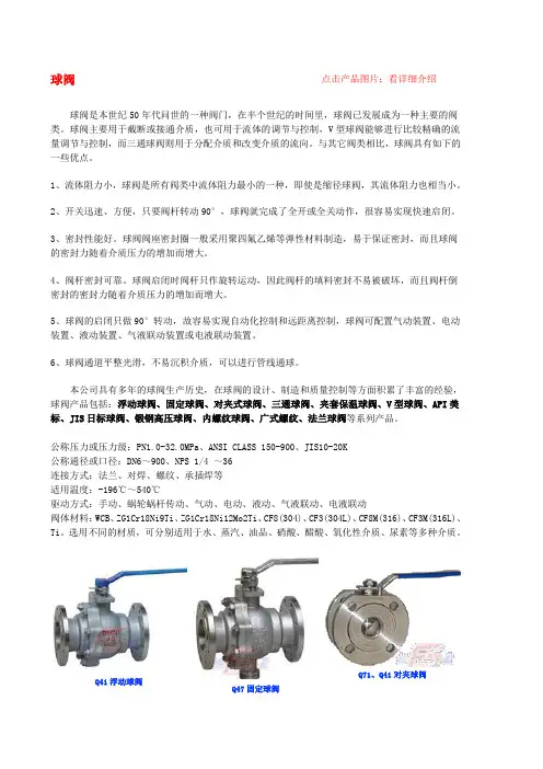
球阀点击产品图片:看详细介绍球阀是本世纪50年代问世的一种阀门,在半个世纪的时间里,球阀已发展成为一种主要的阀类。
球阀主要用于截断或接通介质,也可用于流体的调节与控制,V型球阀能够进行比较精确的流量调节与控制,而三通球阀则用于分配介质和改变介质的流向。
与其它阀类相比,球阀具有如下的一些优点。
1、流体阻力小,球阀是所有阀类中流体阻力最小的一种,即使是缩径球阀,其流体阻力也相当小。
2、开关迅速、方便,只要阀杆转动90°,球阀就完成了全开或全关动作,很容易实现快速启闭。
3、密封性能好。
球阀阀座密封圈一般采用聚四氟乙烯等弹性材料制造,易于保证密封,而且球阀的密封力随着介质压力的增加而增大。
4、阀杆密封可靠。
球阀启闭时阀杆只作旋转运动,因此阀杆的填料密封不易被破坏,而且阀杆倒密封的密封力随着介质压力的增加而增大。
5、球阀的启闭只做90°转动,故容易实现自动化控制和远距离控制,球阀可配置气动装置、电动装置、液动装置、气液联动装置或电液联动装置。
6、球阀通道平整光滑,不易沉积介质,可以进行管线通球。
本公司具有多年的球阀生产历史,在球阀的设计、制造和质量控制等方面积累了丰富的经验,球阀产品包括:浮动球阀、固定球阀、对夹式球阀、三通球阀、夹套保温球阀、V型球阀、API美标、JIS日标球阀、锻钢高压球阀、内螺纹球阀、广式螺纹、法兰球阀等系列产品。
公称压力或压力级:PN1.0-32.0MPa、ANSI CLASS 150-900、JIS10-20K公称通径或口径:DN6~900、NPS 1/4 ~36连接方式:法兰、对焊、螺纹、承插焊等适用温度:-196℃~540℃驱动方式:手动、蜗轮蜗杆传动、气动、电动、液动、气液联动、电液联动阀体材料:WCB、ZG1Cr18Ni9Ti、ZG1Cr18Ni12Mo2Ti、CF8(304)、CF3(304L)、CF8M(316)、CF3M(316L)、Ti。
选用不同的材质,可分别适用于水、蒸汽、油品、硝酸、醋酸、氧化性介质、尿素等多种介质。