LGT-350-I 单面连续涂布机说明书
- 格式:doc
- 大小:52.00 KB
- 文档页数:7

LDT-350(12m)单面间歇涂布机操作使用说明书广州兰格电气设备有限公司Tel: (020)34876598/61920419目录概述一、单面间歇涂布机的组成部分二、单面间歇涂布机的工作原理三、单面间歇涂布机控制系统简介四、单面间歇涂布机控制屏及人机界面简介五、单面间歇涂布机开机过程六、触摸屏各画面和收卷架现场控制屏功能七、极片长度、间歇位和划线位的调整方法八、常见问题及处理方法九、刮刀和辊间间隙位的调整十、附录概述将浆料涂覆在正负极基带上是锂离子电池生产过程中的主要工序之一。
我厂生产的LDT-350单面间歇涂布机能够完成将正负极浆料分别按不同型号的电池而设定的数值准确、均匀的涂覆在铝铂和铜铂上。
涂料时直接留出间歇位,免除后面的刮片工序,从而提高了产品质量和生产效率。
一、单面间歇涂布机的组成部分和技术参数1 、单面间歇涂布机的组成(1)涂料部份(涂辊和背辊)(2)放卷和放卷纠偏部份(3)收卷和收卷纠偏部份(4)基带纠偏部份(5)张力部份(6)干燥部份2、技术参数(1)最大涂布速度:8m/Min(2)最大涂布宽度:400mm(3)最大涂布长度:连续涂布:无限长间歇涂布:单段3000 mm段数:3段(4)间歇位长度:3~500 mm(5)涂布厚度均匀度:≤±4μm(干厚度误差)(6)涂布长度精度:±0.5mm(7)正反面间歇位同步误差:±0.3mm(8)基材厚度:铝箔0.015 mm ---0.030 mm,铜箔0.010 mm ---0.030 mm(9)收放卷纠偏精度:±0.2mm(10)烘箱干燥温度:常温~160℃(11)电源:3~380V/50Hz(12)装机容量:45kw(13)烘箱恒温后功耗:小于25kw二、单面间歇涂布机的工作原理放卷系统将基带放出,经过恒张力调节后进入涂料部份,在涂料处,由背辊牵引基带,涂料辊将其上面的浆料印涂在经过背辊的基带上。
涂布机操作规程一、运行准备阶段1、启动前应仔细检查以下各项:A、所有导辊是否清洁,否则涂层弄脏,硌纸就会造成断纸。
B、气动装置是否动作灵活准确,阀门开关是否灵活。
C、所有的轴承和传动器是否良好(减速器)。
D、所有电机及控制设备是否良好。
E、所有压力表、真空表、温度表是否正常,是否指在零位。
F、所有安全防护设备(踏板、栏杆、等)是否牢固完好。
G、蒸汽管道的阀门通风设备热风系统的阀门启闭是否正常。
(1)、烘箱的手动阀门是否打开(2)、烘箱的疏水器阀门是否打开(3)风机冷却水阀门是否打开(4)风机补充风门开度是否一致H、各部分螺栓是否拧紧,有无松动现象。
2、打开冷却水:收卷、光泽缸、空压机、风机3、热风机循环系统应在启动前约30分钟,先通蒸汽和加热散热器,避免蒸汽突然进入水冷的散热器,而产生大量的冷凝水,冲击设备,同时也为了避免引风机冷态全开运行,造成电机超负荷被烧毁。
4、喷雾装置处于停止状态,喷雾的作用:防止橡胶老化。
(大)涂布不均匀,断纸,降低涂料的固含量和粘度,(小)降低背辊的使用寿命。
5、刮刀装置处于下降阶段6、各压力气胎处于无压状态。
7、各涂布头涂料处于循环状态。
8、引纸前10分钟开启热风机,烘箱预热140°左右。
二、引纸阶段1、检查原纸正反无误,三声铃响启动设备,以20米每分钟引纸。
2、将纸幅按纸张的运行方向进行引纸3、引纸过程中注意事项:A、引纸过程中做到什么部位引纸人员必须跟上B、引纸过程中,保持纸幅紧张,避免纸张过松引起带料跑偏,运行打皱现象及时投入张力。
C、当纸进入3号调态缸,开启1号、4号、5号烘箱,打开气刀,风机装置,1号刮刀气刀开始涂料,有利于提高成品率,避免浪费,避免纸引过干,造成断纸D、当纸进入压光机后,检查纸张松紧情况,合适后启动加压装置。
E、、当纸进入卷纸机后,卷好纸后,检查各部位张力是否一致。
合适后一声铃响通知主控台,开启整个热风系统,,2号刮刀开始带料,进入运行状态。
a media will appear. Select a media then press ENTER.Insert/Remove a USB Flash DriveInserting a USB Flash Drive –Insert straight-in until it fits into place. Removing a USB Flash Drive –Withdraw the USB Flash Drive[Movie] – Start video media’s playback or displays the [MOVIE] menu.[Photo] – Displays [PHOTO] menu. (page 29-30)[Music] – Displays [MUSIC ]menu. (page 28)[Setup] – Displays the [Setup] menu.(page 18-22)First levelSecond levelThird level[4:3 Letter Box] – Select when a standard 4:3 TV is connected. Displays theatrical images with masking bars above and below the [4:3 Pan Scan] – Select when a standard 4:3 TV is connected. Displays pictures cropped to fill your TV screen. Both sides of the picture are cut off.[16:9 Original]–Select when a 16:9 wide TV is connected.The 4:3 picture is displayed with an original 4:3 aspect ratio, with black bars appearing at the left and right sides.Select when a 16:9 wide TV is connected.The 4:3 picture is adjusted horizontally (in a linear proportion) to fill the entire screen.Select a language for the [Setup] menu and on-screen display.Disc Menu / Disc Audio / Disc SubtitleSelect the language you prefer for the audio track (disc audio), subtitles,and the disc menu.Refers to the original language in which the disc wasPress ENTER to select another language. Use number but-tons then ENTER to enter the corresponding 4-digit number according to the language code list on page 32.[Off] (for Disc Subtitle) –Turn off Subtitle.(Digital Audio Output)Select the output sound format when a device equipped with a HDMI or Digital Audio input jack is connected to the HDMI OUT or DIGITAL jack on this player.[PCM Stereo] –Select if you connect this unit’s HDMI OUTAUDIO OUT jack to a device with two-channel digital stereo [PCM Multi-Ch] (HDMI only) –Select if you connect this unit’sjack to a device with multi-channel digital decoder.[DTS Re-Encode] –Select if you connect this unit’s HDMI OUT AUDIO OUT jack to a device with DTS decoder.To access the any features in [LOCK] settings, you must enter the 4-digit security code you have created.If you have not entered a password yet, you are prompted to do so. Enter a 4-digit password and press ENTER. Enter it again and press ENTER toYou can create, change or delete the password.Enter a 4-digit password and press ENTER. Enter it again and press ENTER to create a new password.Enter the current password and press ENTER.Enter a 4-digit password and press ENTER. Enter it again and press ENTER to create a new password.Enter the 4-digit password and press ENTER to delete theTrackAll– Selected portion will be repeated continually. (Audio CD only)– The tracks or files will be played back in random order.Allrandom order.repeatedly to select a Random () or Random All (All) mode icon. The tracks or files will be played in random order. To return to normal playback, press REPEATTitle/Track – Current title/track number/total number of titles/tracks. Chapter – Current chapter number/total number of chapters.Time – Elapsed playing time.Audio – Selected audio language or channel.Subtitle – Selected subtitle.Angle – Selected angle/total number of angles.If no button is pressed for a few seconds, the on-screen display title number cannot be selected on some discs.An item may not be available on some discs or titles.If BD interactive title is playing back, some setting information isWhen the USB Flash Drive is connected and a disc is inserted simultaneously, the menu for selecting a media will appear. Select a media then press ENTER.You can start the slide show by pressing PLAY(N) while photo file is selected in the [PHOTO] menu.On the [PHOTO] menu, use red or blue button to move to the first or the last file and green or yellow button to move to the previous or next You can change the content list view by pressing DISPLAY Use b B to advance to the previous or next file.b c d e f g h。
一、校线当机器组装完毕,线缆走线装配完成以后,在断电的情况下,●先用万用表检查主回路,检查三相之间电阻值是否正常及走线是否正确(断路器没有合时应该是无限大,建议用万用表的200欧档测量,但前提是三相没有接错线或没有短路时),●再检查控制回路是否正常(F1、F2、F3、F4等之间的电阻值及走线是否正确,建议用万用表的200欧档测量,要确保没有接错线,是按图纸走线)●再检查24V、10V、PLC及变频器的接线和电阻值是否正确,(建议用万用表的1K欧档测量,24V的电源输入电阻应该为无限大,24V 的输出电阻要根据所接负载的大小来确定,一般为250欧-500欧左右,10V电源的输入电阻为无限大,输出电阻的大小要根据所接电位器的多少来确定,(如正常有五个电位器时,理论计算值为1K,实际值就是600-900欧),●检查PLC电源及所有接线是否正确,重点检查PLC电源走线和COM接线,检查接线是否与图纸相同,检查强弱电有没有串接,检查PLC输入、输出线是否正确。
●检查变频器输入电源线,输出电机线的接线及线之间的电阻值(根据电机的功率来确定电机侧阻值的大小),检查变频器的启动信号及编码器信号、速度给定是否正确。
●电机运转前要进行绝缘测试(在常温下绕组对地及绕组之间的绝缘电阻大于200兆欧),测量各相之间的电阻值,电机运转前要得到机械的同意。
所有的条件都满足后方可送电,送电的步骤基本同上,先把所有的断路器打到分的状态,然后把主断路器打到合的状态,然后用万用表确定电压即其它的状态是否正常,正常后再送控制电源,先送隔离变压器前的断路器,然后检查变压器的输出电压是否正常,确定后可送其它的电源,但必须分步骤的送,做到一步一个脚印,做到小心谨慎,条理清楚。
◆照明线要外加塑料护套,发热管在使用前必须用万用表测量其阻值,然后用兆欧表测量其阻值(应大于200兆欧)。
以上内容为校线的大致步骤,供现场安装人员参考。
二、变频器参数设定这里主要以G7变频器为说明对象,台达变频器同一原理可参考说明书。
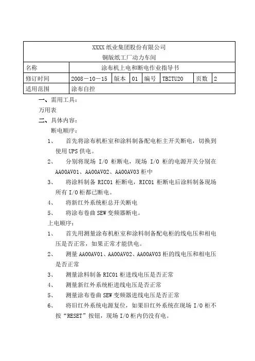
XXXX纸业集团股份有限公司
铜版纸工厂动力车间
名称涂布机上电和断电作业指导书
修订时间2008-10-15 版本 01 编号TBZTU20 页数 2 适用范围涂布自控
一、需用工具:
万用表
二、具体内容:
断电顺序:
1、首先将涂布机柜室和涂料制备配电柜主开关断电,切换到
使用UPS供电。
2、分别将现场I/O柜断电,现场I/O柜的电源开关分别在
AA00AV01、AA00AV02、AA00AV03柜中
3、将涂料制备RIC01柜断电,RIC01柜断电后涂料制备现场
所有I/O柜都已断电。
4、将新红外系统柜总开关断电
5、将涂布卷曲SEW变频器断电。
上电顺序:
1、首先用测量涂布机柜室和涂料制备配电柜的线电压和相电
压是否正常,如果正常才能供电。
2、测量AA00AV01、AA00AV02、AA00AV03柜的线电压和相电压
是否正常
3、测量涂料制备RIC01柜进线电压是否正常
4、测量新红外系统柜进线电压是否正常
5、测量涂布卷曲SEW变频器进线电压是否正常
6、将旧红外系统电源复位,如果旧红外系统在现场I/O柜不
按“RESET”按钮,现场I/O柜内仍没有电。
三、注意事项及相关案例:
1、如果长时间UPS不能提供足够的电,则首先将CPU由运行状态转换到停止状态否则突然断电会引起数据丢失。
四、补充修改内容:
修改内容修改原因修改人确认人时间。
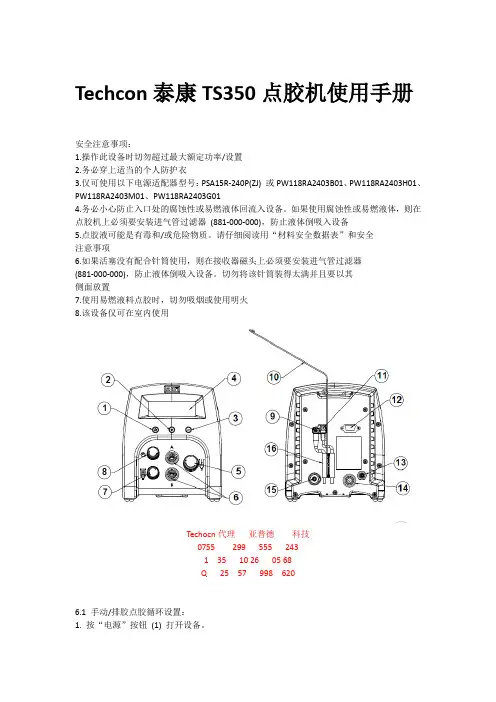
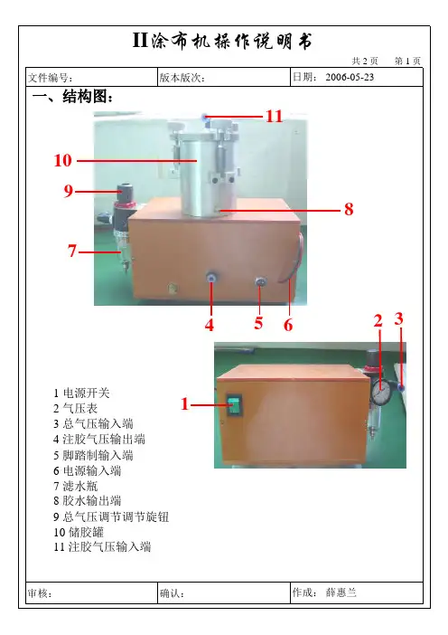
Techcon泰康TS350点胶机使用手册安全注意事项:1.操作此设备时切勿超过最大额定功率/设置2.务必穿上适当的个人防护衣3.仅可使用以下电源适配器型号:PSA15R-240P(ZJ) 或PW118RA2403B01、PW118RA2403H01、PW118RA2403M01、PW118RA2403G014.务必小心防止入口处的腐蚀性或易燃液体回流入设备。
如果使用腐蚀性或易燃液体,则在点胶机上必须要安装进气管过滤器(881-000-000),防止液体倒吸入设备5.点胶液可能是有毒和/或危险物质。
请仔细阅读用“材料安全数据表”和安全注意事项6.如果活塞没有配合针筒使用,则在接收器磁头上必须要安装进气管过滤器(881-000-000),防止液体倒吸入设备。
切勿将该针筒装得太满并且要以其侧面放置7.使用易燃液料点胶时,切勿吸烟或使用明火8.该设备仅可在室内使用Techocn代理亚普德科技0755 299 555 2431 35 10 26 05 68Q 25 57 998 6206.1 手动/排胶点胶循环设置:1. 按“电源”按钮(1) 打开设备。
2. 按“模式”按钮(2) 直到显示器上出现“PURGE 排胶”。
3. 通过旋转压力调节旋钮(5)直至所需要的点胶压力显示出来4. 填充针筒或使用预封装的胶合剂后,将注射器附在接收器磁头组件上。
确保注射器固定于恰当的位置。
5. 将接收器磁头组件的插入端连接到其中一个气式点胶出口(6)。
6. 如果需要真空抽吸,逆时针旋转真空压力旋钮(7),所需要的真空压力可以显示出来。
7. 压住“脚踏开关”以激活点胶循环。
(此刻手动/排胶模式即被激活)6.2 自动点胶循环设置6.2.1 程序选择1.按下设置按钮(3)直到“P:”开始闪烁2.旋转程序选择按钮(8)选择所需要的程序6.2.2 时间设置1.按下模式按钮(2)选择需要的时间模式2.按下并释放设置按钮(3)直到时间里(:) 开始闪烁.3.旋转时间旋钮(8)选择需要的点胶时间4.压下踩脚踏开关启动点胶周期6.3 培训模式设置在培训模式下,只要脚踏开关处于压下状态,设备就会累计时间。

涂布机操作规程涂布机操作规程1.涂布机设备操作规程为确保安全生产,维持涂布机的正常运行,特制定本操作规程:1.1开机前准备1)检查各电气开关,联线有无脱落或破损等异常现象。
2)按工艺片路要求在常温停机状态下穿好牵引带。
3)启动排风设备。
4)确认在涂布机房内无任何明火(如电炉等)。
5)涂布机控制柜和干燥箱体外壳必须可靠接地。
1.2开机程序1)合上总电源开关及控制柜上电源开关。
2)在张力控制器上设定好初始值(一般为180~280)及分频数(通常为20~50)。
3)设定涂布工作方式和相关参数(涂布速度、段长、间隙长度、辊速比等),而后接通压缩空气(调节气动控制箱调压阀使气动压力在0.2~0.3Mpa之间);4)启动干燥风机和干燥温控仪。
5)接通自动纠偏和张力控制器电源。
6)设备各段温度均已达到工艺要求温度;7)给涂布装置料斗加料,同时启动涂布机,进行涂布。
1.3关机程序1)确认被涂布极片已卷绕完毕,而后停车。
2)关闭设备加热器电源,待各段温度降至60摄氏度以下时,停止干燥风机及其他风机;3)停止压缩空气。
4)断开纠偏柜和控制柜上的电源。
1.4注意事项1)操作人员必须接受岗前培训并经考核合格后方可上岗,并应严格遵守本操作规程。
2)除了必需的维护人员外,严禁非本岗位人员操作设备或改变设置参数。
3)辊速比建议设定在1.3~1.5范围内。
4)必须确认干燥风机已经启动后才能启动空气加热器。
5)调整涂布辊和背辊的间隙时应以涂布辊上的浆料刚好擦去而又不卡住背辊为原则,必须保证两辊的平行、间隙一致(必须有间隙)。
6)在重新设定参数后,一定要按置入按钮才能改变参数。
7)每班停机后须立即用酒精或丙酮清洗好料斗、刮刀、涂布辊及背辊等,表面不得有刮伤和损伤。
8)注意保持背辊气缸及直线滑轨的清洁及润滑。
9)机器轴承部位须定期加油润滑,减速箱须定期换油或补充。
10)运行过程中一旦发现问题必须即时记录并通知相关部门,以便及时处理。

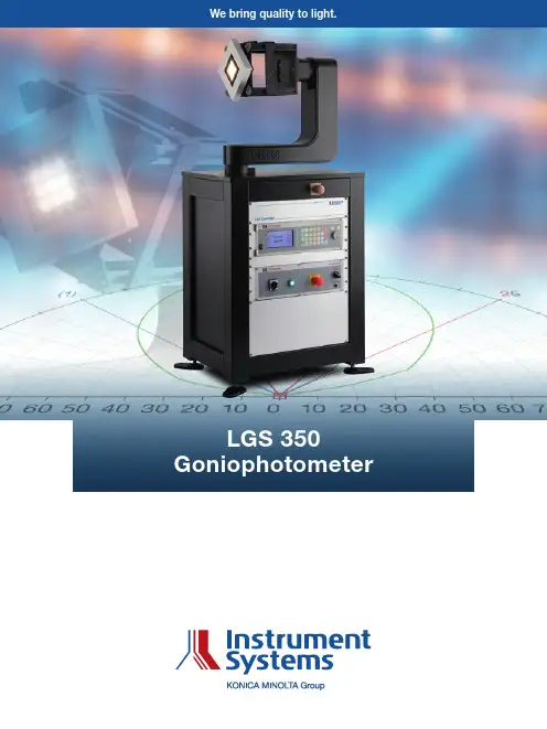
The LGS 350 Goniophotometer/Goniospectroradiom-eter was developed for the analysis of angle-dependent spatial radiation properties from small to medium-sized SSL luminaires and lamps, and LED modules. The test specimen is operated in a horizontal burning position and measurements can be taken at an angular range of ±160° in the gamma axis. The angular resolution of 0.01° means that very fine measuring grids can be recorded with a high level of accuracy and reproducibility. The LGS 350 is compliant with all the relevant specifications in conformity with CIE, DIN and IES standards.Combined with a spectroradiometer from Instrument Systems, all spectral quantities such as color coordi- nates, color temperature and even color rendering index can be determined as a function of angle. C-plane mea- surements can also be carried out very quickly “on the fly” using the DSP 10 Photometer. This provides an over-view of the spatial light distribution for the test specimen very quickly. The measured data can be displayed as different diagrams including the Isocandela diagram. The measurement results can also be exported in standard file formats.The turnkey systemThe LGS 350 comprises the actual goniometer with a sample plate for fixing the test specimen and the LGS Controller that drives the stepper motor and the angle display. If a photometer is used, the LGS Controller also displays the measured values in candela or lux. The LGS 350 is supplied in two versions:↗ Goniometer with stable base and integrated LGS Controller↗ Goniometer in benchtop version with separate 19” rack for the LGS ControllerPerfect for mid-sized SSL light sources and LED modulesLGS350-110 benchtop versionDefinition of the Type C coordinate system2The optical probe of the spectroradiometer or the photo-meter head for taking measurements is placed outside the photometric distance and attached to a stray light tube adjusted to the measuring distance and the sample size. The measuring distance should be 10 to 15 times the diameter of the light source being tested.The goniometer unitThe LGS 350 Goniometer rotates the test specimen in the gamma and C axes. The horizontal alignment of the CIE 121-1996 coordinate system facilitates a particularly compact test setup. Both axes can be operated simul-taneously and can be moved smoothly and with minimal vibration even when the test specimen is subject to maximum load. If a suitable sample mount is used, the system can also be deployed as a Type B goniometer. The design features a highly torsion-resistant frame with high-precision gearbox bearings. This guarantees a high level of reproducibility for sample positioning of ≤0.1° for a load even with maximum sample weight of 8 kg. Sample plate and electrical connectionThe sample plate measures 100 x 100 mm2 and has2 x 2 size 6 grooves and 2 x M6 x 12 tapped threads. This allows customer-specific specimen holders to be conveniently mounted on the plate with bolts. The sample plate is also provided with fitting bushes to ensure reproducible fixing.Sample plate with sample connectorThe electrical sample connector is a compact compo-nent mounted between the C axis gearbox and the sample plate. It therefore swivels with the sample plate and allows the lamp to be connected with short cables without any hazard of the cables becoming ruptured. The sample connector has two safety banana sockets and has been designed for a maximum voltage of300 V. The LGS ControllerLGS Controller for benchtop versionThe LGS Controller drives the goniometer and is either integrated in the goniometer base (LGS350-100) or in a separate 19” rack (LGS350-110). Apart from accommo-dating the LSG Controller, both versions offer space for additional modules. A large 19” rack can also be supplied as an option with a height of 170 cm. This allows addi-tional power supply units or measuring instruments to be integrated.User-friendly remote controlWould you like quick and easy manual positioning for both axes? The convenient RecoCAN remote control can be used for fine adjustment in increments of 0.01°. RecoCAN allows users to align the goniometer on the optical axis of the test specimen with ease.RecoCAN remote control3The full spectrum of measuring options The comprehensive accessories significantly expandthe range of measuring options offered by the LGS 350.A universal sample holder for mid-size LED modulesand lamps, and a lamp holder for standard fittings ofthe type E10, E27, E40, etc. are supplied.Sample holder with LED-850 test adapter for single LEDsSample holders for TEC test adapters of the LED-850 and LED-870 series are available to plug and go. The test adapters facilitate the analyis of thermal properties of single LEDs, LED arrays and modules using minimum resources. The Peltier elements integrated in the test adapters permit adjustment over a wide temperature range from +5°C to +85°C. Photometric and colorimetric measurements The LGS 350 is compatible with all spectroradiometers supplied by Instrument Systems. The CCD array spec-trometers in the CAS series are ideal because they feature a very large dynamic measuring range and very short measuring times. The use of a spectroradiometer offers the unique advantage that photometric, radio-metric and colorimetric quantities can be obtained from the measured spectral data. Specifically for SSL lamps and LED modules, measurement accuracy is superior to filter-based photometers and colorimeters. However, the LGS 350 can also be combined with the very fast, integral photometers from Instrument Systems,which permit scanning of the entire intensity distributionSample holder with LED-870 test adapter for LED arrays and modules4within a few minutes. Even pulse-width modulatedLEDs with cycle frequencies of 80 Hz to 10 kHz can be measured precisely using the adaptive filtering anddigital signal processing of the innovative DSP 10 Photo-meter.Measurement sequences in SpecWin ProSpecWin Pro software powers the outstanding produc-tivity of the LGS 350. Two measurement modes are supported. Firstly, the sequence mode allows spatial radiation patterns of the test specimen to be recorded for gamma and C axes in defined angular increments. All measured data are available for subsequent evalua-tions. Secondly, the test series mode permits definition of arbitrary measurements with any definable sequence of angular positions.DSP 10 Photometer with stray light tube on standOther add-ons of SpecWin Pro software and appropriate instrumentation also permit current, voltage and tem-perature to be included in the goniometric analysis as control and measured parameters. For example, Keithley 2400 and Keithley 2600 series sourcemeters, and other DC and AC voltage sources can easily be installed as an add-on.SpecWin Pro also supports high-precision determina- tion of radiant power or luminous flux by angular inte-gration of radiant intensity and luminous intensity. If a spectroradiometer is used as a measurement device, the individual spectra of all angular positions are also aggregated. This ensures genuine integration of theentire spectral radiant power and hence precise calcula-tion of the colorimetric quantities. This is an advantage not offered by competing products.Luminous intensity distribution of various LED modulesDisplay options and output formatsThe graphics window is the central element of the user interface of SpecWin Pro. This window displays all mea-surements. Five different display options are available for the spatial radiation pattern: radial display (luminous intensity distribution curve), semi-radial and cartesian view, and a two-dimensional spherical display with Iso-candela lines and a 3D view. All displays accept photo-metric, radiometric, colorimetric and spectral measured data for evaluation. The measured data obtained can also be exported in IES and EULUMDAT format for use in simulation programs.3D display and CCT distribution of a SSL lamp28262803278127582735271226892666264326202598-90°180°90°0°90°0°C C T / K90 80 70 60 50 40 30 20 10 0 10 20 30 40 50 60 70 80 90 100Photometric Integral / %γ / °0(1)25-90905Technical specificationsInstrument Systems is working continuously to develop and upgrade its product range. Any technical changes, mistakes and printing errors do not form grounds for claiming compensation for damages. Our General Terms and Conditions are applicable in all other respects.6Ordering information7Instrument Systems GmbHKastenbauerstr. 281677 Munich, Germany Tel.: +49 89/45 49 43-0Fax: +49 89/45 49 43-11E-mail:************************** b _l g s 350_e n _V 1.2。
产品使用说明书TY-TF660A型涂胶机目录1. 概述 (5)2.结构特性 (6)3.基板尺寸 (6)4.基板厚度 (6)5.使用电压 (6)6.设备主要结构件要求 (6)7.控制系统 (8)8.主要技术参数 (9)9.主要部件产地 (9)10.结构简图 (10)11.安装和调试 (10)12.开关功能 (11)13.设备操作 (12)14.故障分析与排除 (13)15.维护与保养 (14)16.随即文件清单 (15)17.技术服务 (16)1.概述TY-TF660A型涂胶机是为电子元件厂研制的专用设备之一,是用于对超薄金属片进行双面涂曝光油墨的专用设备。
TY-TF660A型涂胶机具备手动和自动操作方式,操作简洁方便。
是目前较先进的设备之一。
TY-TF660A型涂胶机是在单面涂胶机的基础上改良的双面涂胶新机型。
是将清洗干净的0.05~2.0金属片上双面涂光刻胶的专用设备。
本机采用OMRON继电器为中央控制单元。
涂胶采用两轮方式,光刻胶可循环使用。
涂胶驱动部分采用可调速电机控制,传动平稳。
涂胶轮对于抗丙酮,乙酸乙酯,N-甲基吡咯烷酮等化学药品效果良好,具有全自动功能,生产效率高。
2、结构特性:附图:TY-TF660A型涂胶机TF660A型涂胶机实物图3. 基板尺寸:宽度≤600mm(可以根据贵公司材料随时调整)4.基板厚度:0.05~2㎜5.使用电压:220V 50Hz 0.3KW6、设备主要结构件要求:6.1 机架:如下图:方通方通6.1.1 材料:优质空心方不锈钢焊接成型,6.2.工作台板6.2.1 材料:不锈钢台板6.2.2 工作台精度:平面度≤±0.1mm 6.3 侧板部分:如下图所示:6.3.1材料:主体优质中碳钢结构6.3.2表面处理:镀亮铬防锈处理。
6.4 运行部分:6.4.1传动电机:200W 调速电机6.4.2传动轴:304不锈钢芯加硅橡胶导轮。
6.4.3涂胶辊:耐各种溶剂特种橡胶制成。
一. 目的为规范涂布生产的操作,确保生产的顺利进行,有效地开展与质量目标相关的活动,以此来保证产品质量的稳定性。
二. 范围涂布机的操作。
三. 内容1.涂布机操作及功能说明2.单项作业指导四. 开机操作指导1.在C1线车间南面辅机配电柜中,开启C4线空压机电源,在空压机上点I键,启动空压机,确认空压机无异常报警即可,至C4线北面辅机处,打开总气源进气管,确认储气罐压力在0.6~0.8MPa之间。
2.打开C4线天然气总阀门,确认燃烧头进气压力表在4~6kPa。
3.在C4线拌硅间配电箱中,合上涂布机、冷冻机、热风炉总电源,缓冲间、涂硅间、拌硅间、更衣间的排风打开。
4.在C4线北面辅机电箱柜,合上冷冻机电源、循环水泵电源、干燥机电源、冷冻机进水泵电源,开启车间排风电源。
关上配电箱,在冷冻机操作面板上,点“启动”键,开启冷冻机,按菜单键,按照工艺要求设置所需温度。
5.根据需要,在C1线车间南面辅机配电柜中合上蒸汽锅炉电源,打开控制面板上开关。
6.按《开机清洁注意事项》清洁整条生产线。
7.在涂布机主控柜电箱中合上电源,复位主机所有紧急停止按钮,按下电源准备按钮,卸下放卷接纸压臂的安全锁。
8.根据产品生产工艺,选择相应的穿纸路线,主要考虑收放卷方式、是否印刷、涂头选择,在引纸过程中调整对边传感器位置并按下对边启动。
9.在热风炉电箱中合上主电源,在电箱面板上打开热风炉电源控制,指示灯亮起,按下循环风机“开”,再分别将燃烧机开关和大火允许开关打开,根据工艺单要求设定燃烧温度和回风温度。
10.根据工艺要求,在放卷架人机界面选择打开各节烘箱风机及排风风机,根据工艺单要求设置排风风机转速。
11.根据工艺需求,将回湿轮处于自动位置。
12.根据工艺要求,打开1-4节烘箱的浓度报警器,并确认1-4节烘箱的手板阀处于中间位置。
13.根据工艺要求,并结合实际走纸情况,设定和调整烘箱张力。
14.等到烘箱温度达到工艺要求的范围后,确认涂头可以正常供料,按下自动启动按钮,主机进入正常联机启动状态。
JLX350-019-BN使用说明书(焊接式FPC)目 录序号 内 容 标 题 页码1 概述 22 特点 23 外形及接口引脚功能 3~44 基本原理 45 技术参数 4~56 时序特性 5~77 指令功能及硬件接口与编程案例 8~末页1.概述晶联讯电子专注于液晶屏及液晶模块的研发、制造。
所生产JLX350-019型TFT模块由于使用方便、显示清晰,广泛应用于各种人机交流面板。
JLX350-019可以显示320列*480行点阵彩色图片,或显示20个/行*30行16*16点阵的汉字,或显示40个/行*60行8*8点阵的英文、数字、符号。
2.JLX350-019图像型点阵TFT模块的特性2.1结构轻、薄、带背光。
2.2 IC采用ST7796S,功能强大,稳定性好2.3 显示内容:●320*480点阵彩色图片;●可选用32*32点阵或其他点阵的图片来自编汉字,按照32*32点阵汉字来计算可显示10个字/行*15行。
●可选用16*16点阵或其他点阵的图片来自编汉字,按照16*16点阵汉字来计算可显示20个字/行*30行。
2.4指令功能强:例如可以用指令控制显示内容顺时针旋转90、逆时针旋转90°或倒立竖放。
2.5接口方式:并口 或串行接口方式。
2.6工作温度宽:-20℃ - +70℃;2.7工作温度宽:-30℃ - +80℃;3.外形尺寸及接口引脚功能模块的接口引脚功能引 线 号 符 号 名 称 功 能1 GND 接地 0V2 VDD 供电电源正极 供电电源正极3.3V3 CS 片选 低电平片选4 RS 寄存器选择信号 H:数据寄存器 0:指令寄存器5 WR/SCL 写/串行时钟并口:写功能; 串口:串行时钟6 RD 读 并口:读功能,串口:建议接VDD或VSS7 SDA 串行数据 并口:空串口:做串行数据8 NC NC 空脚9 DB0 I/O 并口:数据总线DB0,串口:建议接VDD或VSS10 DB1 I/O 并口:数据总线DB1,串口:建议接VDD或VSS11 DB2 I/O 并口:数据总线DB2,串口:建议接VDD或VSS12 DB3 I/O 并口:数据总线DB3,串口:建议接VDD或VSS13 DB4 I/O 并口:数据总线DB4,串口:建议接VDD或VSS14 DB5 I/O 并口:数据总线DB5,串口:建议接VDD或VSS15 DB6 I/O 并口:数据总线DB6,串口:建议接VDD或VSS16 DB7 I/O 并口:数据总线DB7,串口:建议接VDD或VSS17 RST 复位 低电平复位,复位完成后,回到高电平,TFT模块开始工作18 IM2/PS 接口方式选择 并口:VSS 串口:VDD19 LEDA 背光电源正极 接3.0V(接3.3V串10欧电阻,接5.0V串39欧电阻)20 LEDK 背光电源负极 接GND表1:模块的接口引脚功能4.基本原理4.1TFT屏(LCD)在LCD上排列着320×480点阵,320个列信号与驱动IC相连,480个行信号也与驱动IC相连,IC邦定在LCD玻璃上(这种加工工艺叫COG).4.2背光参数该型号TFT模块带LED 背光源。
OWNER’S MANUALWASHING MACHINEPlease read this manual carefully before operatingyour washing machine and retain it for future reference.T1103TEF1T1503TEF2T1503TEF0T1503TEF3T1503TEF1T151103TEF1P/No.: The sensor automatically detects the quantity of a Detergent put by a user and the temperature and the quality of water to make the best washing algorithm forwashing and rinsing, which can give the best washing effect.SMART CLEANINGThe purpose of this cycle is to optimize detergent residues during the washing and rising cycles,in order to implement this effect,the washer adds more rinsing times by I-sensor. Rinse can be added until max 5 times.FUZZY logic controlA built-in load sensor automatically detects the laundry load and amicroprocessor optimizes washing conditions such as ideal WATERLEVEL and washing time.STARTAdvanced technology is built into the Electronic Control System whichensures the best washing result.Turbo drum washingWhen "Punch + 3" washing wings turn, the washingtub turns in the opposite direction. This makes theboth sides current of water which improve wash-performance by rubbing clothes strongly.3 step washing makes the best washing performance with low tangling.” Part can be different according to the model.Nylon net is not supplied by LG.Using Fabric SoftenerDo not mix with Detergent or bleach.Never pour fabric softener directly on clothes. It may stain them.Do not stop the washer during the first spin for timely dispensing.Option washing is not designed to be used with fabric softener dispenser.If desired, pour the recommended amount of liquid fabric softener into the right-hand e only liquid fabric softener.Dilute with water to the maximum fill line.Scrud(Waxy Build up)Scrud is the name given to the waxy build-up that can occur within any washer when the fabric softener comes into contact with Detergent. This build-up is not brought about by a fault in the machine. If scrud is allowed to build-up in the machine it can result in stains on your clothes or an unpleasant Never pour undiluted liquid bleach directly onto clothes or into the wash basket.This may cause change of color or damage the laundry.Do not pour powdered bleach into bleach dispenser.Do not use or mix liquid chlorine bleach with other household chemicals such as toilet cleaners, rust removers, acid or products containing ammonia. These mixtures can produce dangerous fumes which can cause serious injury or death. To reduce the risk of fire or serious injury to persons or property, comply with the basic warnings listed below:• Read and comply with all instructions on stain removal products.• Keep stain removal products in their original labeled containers and out of children’s reach.• Thoroughly wash any utensil used.• Do not combine stain removal products, especially ammonia and chlorine bleach. Dangerous fumes may result.• Never wash items which have been previously cleaned in, washed in, soaked in or spotted with gasoline, dry cleaning solventspushed7 8 • 9 10 1 2 • 3 4 5 • 6 7TUB DRY 60 90 120TUB DRY as the button is pushed.you to select COLD WARM (HOT&COLD) HOT COLD respectively.Default setting is COLD.* Because the detecting ability of the sensor may be decreased by using it for a long time, periodically use (refer to page 21)• The following settings are indicated 4 512 1416...46483 HOUR.• To cancel delay time, turn the power switch off.(refer to page 24)follows:If the current washing condition (Detergent quantity, Water Temperature, water quality, etc.) is determined as better than the standard one, it optimizes the algorithm to save the energy by decreasing washing time/strength,and the LED automatically turns to red.If the current washing condition is determined as worse than the standard one, it optimizes the algorithm by increasing washing time/strength, and the LED automatically turns to orange.If the current washing condition is determined as equal to the standard one, the algorithm has no change and the LED turns to green.• program selections light up in sequence as follows: FUZZY(Normal)WOOL QUICK WASH JEANS SMART CLEANING SILENT FAVORITE TUB CLEAN FUZZY(Normal) etc.Select the desired program by pressing the button.laundrythe Detergentmode automatically selects the .AUTO OFF1125432• Select theQUICK • Add the appropriate quantity of Detergent as manufacturer’s instructions• Add the appropriate quantity of Detergent as indicated by theWATER LEVEL next to manufacturer’s instructions1532• Select the panel.• Spread1532• Select the delicate fabrics such as lingerie and • Use neutral Detergentappropriate for the washing wool.1532• Select theClose the lidFinishSTART PAUSE• The pulsator rotates for 8 seconds to detect the laundry load.• Then the WATER LEVEL and the amount of Detergent to be used will be shown and water will be supplied.• Water will be supplied for 2has absorbed.• When the wash program ends, the automatically.356767644764764POWER Ex-Large WATER is set automatically.Select "Air Dry" 30min-Use this mode to keep inner tub from getting moldy caused by remaining moisture.- Do not place any laundry inside tub.- Use this mode once a week.Caution) For better performance, put drain hose down to the floor so that water inside will be completely drained out.Select “Air Dry” above 1 hour- Use this mode to reduce the drying time by minimizing remaining moisture on the laundry. - In general, this is very effective on synthetic items(100% polyester).- Do place laundry which is evenly distributed(Under 2kg).- For normal clothes : Select 1 hour- For synthetic items(100% polyester): Select 2 hours or 3 hours(on some models)Installing the Anti-Rat Cover (option) Insert the anti-rat cover to be firmly fixed from the back or front of washing machine and screw it632(W) 670(D) 1020(H)In our continuing effort to improve the quality of our appliances, it may be necessary to make changes to the appliance without revising this manual.For any Suggestion, Opinion & Complaints,T1503TEF2T1103TEF1 T1503TEF3T1503TEF0 T151103TEF1T1503TEF1。
LGT-350-I单面连续涂布机操作使用说明书
广州兰格电池设备厂
Tel: (020)34876598
目录
概述
一、单面连续涂布机的组成部分
二、单面连续涂布机的工作原理
三、单面连续涂布机控制系统简介
四、单面连续涂布机控制屏简介
五、单面连续涂布机开机关机过程
六、极片厚度及边线的调整方法
七、常见问题及处理方法
八、刮刀和辊间间隙位的调整
九、附录
概述
将浆料涂覆在正负极基带上是锂离子电池生产过程中的主要工序之一。
我厂生产的LGT-350-I单面间歇涂布机能够完成将正负极浆料分别按不同型号的电池而设定的参数准确、均匀的涂覆在铝铂和铜铂上。
一、单面连续涂布机的组成部分
1、涂料部份(涂辊和刀)
2、放卷部份
3、收卷部份
4、主驱动部份
5、干燥部份
二、单面连续涂布机的工作原理
主驱动将基带从放卷架上牵拉出来,基带进入涂料部份,在涂料处,浆料涂覆在基带上,然后经过涂辊和刮刀之间的间隙,将料定厚刮平,基带涂上浆料后进入热风干燥箱进行烘烤,烘干的料带经过驱动辊后,收卷架将其收卷。
三、单面连续涂布机控制系统简介
1、该控制系统以调速电机进行主驱动,速度连续无级可调。
2、以三相固态继电器为发热元件的驱动模块,可延长触点的寿命。
3、温度控制采用二级温控电路保护。
四、单面连续涂布机控制屏简介
控制屏上有一个调速器、三个温控仪、加热及风机按钮、电源开关等,如下图示。
五、单面连续涂布机开机、关机过程
1、首先调整好刮刀与涂布辊之间的间隙,使其满足涂布厚度的要
求。
(刀口间隙和辊间间隙的调整另有详细说明)
2、将各烘箱风机、散热风机的进出风门开到合理位置。
3、将基料带穿好,穿料带时尽量将料带放在整个机架的中心线上。
4、当完成上述三步以后,合上电控箱侧面的空气开关,屏上的电
源指示灯亮起,打开控制屏上的控制电源,然后打开三个烘箱
的风机、排湿风机,再开加热器,将温控仪的温度分别设定为
需要的温度,待其升温。
5、待温控仪上的温度升到设定的温度后,把浆料加到料槽中,打
开调速器,将速度调整到适当的驱动速度进行浆料涂布。
6、当涂布完成时,关闭调速器,然后先关掉烘箱的加热器,2分
钟后再关断循环风机和排湿风机即可。
最后关闭控制电源。
当长时间不使用时,断开电控箱侧面的空气开关。
六、极片厚度、边线位的调整方法
(1)极片厚度的调整
测量烘干后的极片的厚度,看它是否和所要求的极片厚度相一致,如果厚度比所要求薄了,则加大刮刀到辊间的间隙,反之减小间隙。
(2)极片边线的调整
如果极片两边需要留出边线来,则应该在料槽中加上挡料板,视实际涂覆的效果适当调整两块挡料板的位置以满足边线的要求。
七、常见问题及处理方法
(1)故障:当打开控制电源开关后,控制电源灯不亮
分析:可能是外电路没有送电,或电柜侧面的自动开关没
有合上。
解决:将外电路送上电后合上电柜侧面的空气开关。
(2)故障:开机时三个烘箱的加热器无法起动
分析:可能开机和关机的顺序不对。
解决:按照顺序进行,开机时,先开风机,后开加热器;
关机时,先关加热器,后关风机。
(3)故障:在正常开机的过程中,面板上的温控器和加热指示灯突然息灭,加热停止。
分析:可能是二级温度保护所致。
此时可能是二级保护温
控器的设定温度偏低,也可能是循环风门开度太小
或风机故障或停转。
解决:将电控箱内的二级保护温控表的设定温度调高,比
屏上的设定温度高50-80度;将循环风门开大;检
查风机是否损坏,如有损坏,立即报请专业维修人
员进行维修更换。
(4)故障:基带经常跑偏
分析:可能是机头机、烘箱和机尾架的辊间不平行所致。
解决:报请专业维护人员重新调整机头、机尾和烘箱的平
行度;辊子、辊间的水平度和平行度;以及整台机
器的直线度。
(5)故障:涂完的浆料不能烘干
分析:可能是驱动速度太快;可能是烘箱的温度太低;可
能是风机的风门调得太小或排湿风机没开。
解决:适当降低驱动速度;适当调高烘箱的温度;适当的
开大循环风机和排湿风机的风门。
(6)故障:涂完的极片表面不均匀或有较粗糙的纹路
分析:可能是刮刀刀口没有磨平;可能是钢辊已受损或有
污点;也可能是浆料的浓度和颗粒度太大所致。
解决:重新研磨刮刀刀口;将钢辊上的污点清理干净;调
整浆料的浓度及更换颗粒度较细的浆料。
八、刮刀间隙的调整
(1)刮刀的调整步骤,参见如下示意图:
第1步:当涂布厚度偏厚时,应将刮刀间隙调小。
即调整刮刀手轮将刮刀往下调整。
第2步:当涂布厚度偏薄时,应将刮刀间隙调大。
即调整刮刀手轮将刮刀往上调整。
第3步:经过若干次调整后,涂布厚度应该能满足要求。
九、附录
1.单面连续涂布机电路原理图
2.温控仪说明书。